

Datamax A-Class A-4212, A-Class A-6212, A-Class A-4310, A-Class A-4606, A-Class A-6310 Operator's Manual
...Page 1

Operator’s Manual
Page 2

Page 3

Copyright Information:
CG Times (based upon Times New Roman) and CG Triumvirate are trademarks of the AGFA
Monotype Corporation.
Windows and Windows NT are trademarks of the Microsoft Corporation.
NetWare and Novell are registered trademarks of Novell, Inc.
Ethernet is a registered trademark of Xerox Corporation.
All other brand and product names are trademarks, service marks, registered trademarks,
or registered service marks of their respective companies.
Firmware (Software) Agreement:
The enclosed Firmware (Software) resident in the Printer is owned by Licensor or its
suppliers and is licensed for used only on a single printer in the user’s Trade or Business.
The User agrees not to, and not to authorize or permit any other person or party to
duplicate, or copy the Firmware or the information contained in the non-volatile or
programmable memory. The firmware (Software) is protected by applicable copyright
laws and Licensor retains all rights not expressly granted. In no event will Licensor or its
suppliers be liable for any damages or loss, including direct, incidental, economic, special, or
consequential damages arising out of the use or inability to use the Firmware (Software).
Information in this document is subject to change without notice and does not represent a
commitment on the part of Datamax Barcode Products Corporation. No part of this manual
may be reproduced or transmitted in any form or by any means, for any purpose other than
the purchaser's personal use, without the expressed written permission of Datamax
Corporation.
All rights reserved.
© Copyright 2008 by Datamax Corporation
Part Number: 88-2305-01
Revision N
Page 4

Agency Compliance and Approvals:
UL60950 Information Technology Equipment
C US
Listed
C22.2 No. 950-M93
EN60950
For 230 Volt Operation (Europe):
of a min H05VV-F cord which has a minimum 0.75 square mm diameter
conductors, provided with an IEC 320 receptacle and a male plug for the
Use a cord set, marked “HAR,” consisting
country of installation rated 6A, 250V
Für 230 Volt (Europa):
Benützen Sie ein Kabel, das mit “HAR” markiert ist,
bestehend mindestens aus einem H05VV-F Kabel, das mindestens 0,75
Quadratmillimeter Drahtdurchmesser hat; sowie eine IEC320 Steckdose und
einen für das Land geeigneten Stecker, 6A, 250 Volt.
As an Energy Star Partner, the manufacturer has determined that this
product meets the Energy Star guidelines for energy efficiency.
The manufacturer declares under sole responsibility that this product
conforms to the following standards or other normative documents:
EMC: EN 55022 (1993) Class B
EN 50024 (1998)
Safety: This product complies with the requirements of
EN 60950-1 First Edition
FCC: This device complies with FCC CFR 47 Part 15 Class A.
Note: This equipment has been tested and found to comply with the limits for a
Class A digital device, pursuant to Part 15 of the FCC Rules. These limits are
designed to provide reasonable protection against harmful interference when the
equipment is operated in a commercial environment. This equipment generates,
uses, and can radiate radio frequency energy, and if not installed and used in
accordance with the instructions in this manual, it may cause harmful interference
to radio communications. Operation of this equipment in a residential area is likely
to cause harmful interference in which case the user will be required to correct the
interference at his own expense.
Page 5

Page 6

Page 7

Important Safety Instructions:
Throughout the literature accompanying this unit, the exclamation point within
an equilateral triangle is intended to alert the user to the presence of important
operating and maintenance instructions.
This unit has been carefully designed to provide years of safe, reliable performance.
However, as with all electrical equipment, there are some basic precautions that you should
follow to avoid personal injury or damage to the printer:
• Before using the print engine, carefully read all the installation and operating
instructions.
• Moving parts are present during operation – keep body parts, loose clothing, etc. away
from the mechanism.
• Observe all warning instruction labels on the print engine.
• Mount the print engine securely in the applicator system.
• Do not place the print engine on or near a heat source.
• To protect from overheating, make sure no openings on the print engine are blocked.
• Never insert anything into the ventilation slots and openings of the print engine.
• Do not use the print engine near water or spill liquid into it.
• Ensure that the AC power source complies with the ratings listed for the print engine.
• Do not place the AC power cord where it can be stepped on. If the AC power cord
becomes damaged, replace it immediately.
• Consult only qualified, trained personnel to perform service on this print engine. There
are no user-serviceable parts are inside; do not remove the cover.
Special Instructions
The green check box is intended to alert the user to conventions used within this
;
text or to notable operating details and suggestions.
Page 8

Page 9

Contents
1 Overview.................................................................................................1
1.1 About the Printer............................................................................... 1
1.1.1 Standard Features.................................................................... 2
1.1.2 Optional Features .....................................................................3
1.2 Index to Features and Controls............................................................ 5
1.2.1 Right Hand Models.................................................................... 6
1.2.2 Left Hand Models...................................................................... 7
2 Getting Started .......................................................................................9
2.1 Unpacking ........................................................................................ 9
2.1.1 Contents ............................................................................... 10
2.1.2 Additional Requirements.......................................................... 10
2.2 Installation..................................................................................... 10
2.2.1 Mounting Requirements........................................................... 10
2.2.2 Interfacing a Host................................................................... 14
2.2.2.1 Parallel Port Connections............................................ 15
2.2.2.2 Serial Port Connections.............................................. 15
2.2.2.3 USB Port Connections................................................ 18
2.2.3 Connecting an Applicator......................................................... 19
2.2.4 Connecting Power................................................................... 19
3 Setting up the Printer............................................................................21
3.1 Loading Media................................................................................. 21
3.2 Adjusting the Media Sensor............................................................... 25
i
Page 10

3.3 Loading Ribbon ............................................................................... 26
3.3.1 Right Hand Models.................................................................. 26
3.3.2 Left Hand Models.................................................................... 28
3.3.3 Removing Ribbon ................................................................... 29
3.4 Quick Calibration............................................................................. 30
3.5 Print Quality Controls....................................................................... 30
4 Using the Control Panel.........................................................................31
4.1 Layout ........................................................................................... 31
4.1.1 Ready Mode........................................................................... 32
4.2 The System Menu............................................................................ 33
4.2.1 Media Settings ....................................................................... 35
4.2.2 Print Control .......................................................................... 37
4.2.3 Printer Options....................................................................... 39
4.2.4 System Settings..................................................................... 45
4.2.5 Communications..................................................................... 54
4.2.6 Diagnostics............................................................................ 63
4.2.7 MCL Options .......................................................................... 65
4.3 The Test Menu ................................................................................ 66
4.3.1 Print Quality Label .................................................................. 68
4.3.2 Print Configuration.................................................................. 68
4.3.3 Ribbon Test Label................................................................... 69
4.3.4 Validation Label...................................................................... 69
4.3.5 Print Last Label ...................................................................... 69
4.3.6 User-Defined Label ................................................................. 69
ii
Page 11

5 Operating, Adjusting and Maintaining the Printer .................................71
5.1 Displayed Messages......................................................................... 71
5.1.1 Prompts and Condition Messages.............................................. 71
5.2 Calibration...................................................................................... 74
5.2.1 Standard Method.................................................................... 74
5.2.2 Advanced Entry...................................................................... 76
5.3 Printhead Adjustments ..................................................................... 83
5.3.1 Leveling Cam Adjustment ........................................................ 83
5.3.2 Burn Line Adjustment.............................................................. 85
5.4 Printhead Replacement..................................................................... 86
5.5 Maintenance Schedule...................................................................... 90
5.5.1 Cleaning the Printhead ............................................................ 91
5.5.2 Cleaning the Rollers................................................................ 93
5.5.3 Cleaning the Peel Assembly...................................................... 94
5.5.4 Cleaning the Media Sensor, Media Path, and Peel Bar .................. 96
5.5.5 Cleaning Exterior Surfaces....................................................... 97
5.6 Reset Methods ................................................................................ 97
5.6.1 Soft Reset ............................................................................. 97
5.6.2 Level One Reset ..................................................................... 97
5.6.3 Level Two Reset ..................................................................... 97
5.7 Updating the Firmware..................................................................... 98
5.8 Updating the Boot Loader ................................................................100
5.9 Downloading Fonts .........................................................................101
iii
Page 12

6 Troubleshooting..................................................................................103
6.1 Problem Resolution.........................................................................103
6.1.1 General Resolutions...............................................................103
6.1.2 Warning and Fault Messages...................................................106
6.2 Hex Dump Mode.............................................................................112
7 Specifications......................................................................................115
7.1 Printer Specifications ......................................................................115
7.2 Approved Media and Ribbon.............................................................120
Appendix A.............................................................................................. 123
Module Assignments..............................................................................123
File Handling Messages ..........................................................................123
Cut Behind Setup ..................................................................................125
Appendix B.............................................................................................. 127
Print Resolutions and Widths...................................................................127
Speed Ranges.......................................................................................127
Column & Row Emulation Ranges ............................................................128
Custom Adjustments: Column, Present, & Row Adjust Ranges .....................128
Appendix C.............................................................................................. 129
PE Peel Bar Location ..............................................................................129
PE to A-Class GPIO Adapter Cable ...........................................................129
Appendix D .............................................................................................131
Applicator Interface Overview .................................................................131
Appendix E..............................................................................................139
iv
Page 13

Multi-Language Menu.............................................................................139
Appendix F..............................................................................................143
Saving a Configuration File .....................................................................143
Appendix G..............................................................................................145
Ribbon Saver Overview ..........................................................................145
Warranty Information.............................................................................147
Glossary..................................................................................................149
v
Page 14

vi
Page 15

1
Overview
1.1 About the Printer
Congratulations on your purchase of an A-Class printer. This print engine (hereafter referred
to as “the printer” and, when necessary, by model) is designed for professional integration
into an industrial applicator system.
This manual provides all the information necessary for installat ion , setup and operation of
the printer. To begin printing, refer to the instructions provided with your label-creation
software; or, to write custom label programs, reference the Class Series 2 Programmer’s
Manual on the Accessories CD-ROM, also available at http://www.datamaxcorp.com
The printer’s model number, located on the Serial Tag affixed to the inside of the front
cover, should be used when referencing specific information within this manual.
A-Class 1
Page 16

1.1.1 Standard Features
This printer offers the following standard features:
• Right-handed or left-handed configurations
• Electronics card cage
• 4 MB Flash downloadable program memory
• 16 MB DRAM memory
• Host computer accessible memory for object temporary storage
• Two RS-232 serial interfaces (one of which is also RS-422/RS-485 capable)
• One IEEE 1284 compliant parallel interface
• One USB v1.1 interface
• A programmable GPIO Port
• Backlit ¼ VGA graphics display
• EFIGS (English, French, Italian, German, and Spanish) display languages
• Industry standard bar code symbologies
• Time stamp at print capability with time and date battery back-up
• Static brushes
• Printhead resistance verification
• Configurable fault-handling capability with reprint and void selections
• Parse error-tolerant command language interpretation
• Internal test labels for verification, validation, an d configuration
• Multiple setup restore capability
• Paper retract control after print
• Ribbon low detection and warning
• Power-up, mode, and resident option hardware diagnostics
• Option hardware auto-detection
• Media peel bar
• Media inch counters
• Input line mode (ASCII text input) capability
• Firmware upgrades downloadable
• AGFA Scaleable Font Engine featuring dynamic font attributes
2 A-Class
Page 17

1.1.2 Optional Features (available except as noted)
The following optional features are available:
• DMXNetII and DMXrfNetII
An internal wired or wireless Network Interface Controller for Ethernet
multiple operating system and protocol support, including trap functions.
• Expanded Flash Main Logic CCA
An alternate circuit card assembly with 8MB of Flash memory for storing additional fonts,
graphics, and label templates.
• International Language Printing Capability (ILPC)
An alternate font set, available for standard or expanded memory:
CG-Times (European) Scaleable font (and Enhanced Language Code Pages)
Kanji Gothic B Scaleable font
connectivity with
Simplified Chinese GB Scaleable font
Korean Hangul Scaleable font
• Linerless Cutter
A mechanism specifically designed to cut linerless media after printing.
• MCL
A software tool suite for information collection applications , allowing input data from
peripheral devices (scanners, weigh scales, keyboards, etc.) without the need of a host
computer.
• Remote Control Panel
A hardwired assembly allowing remote operation (six feet [1.8 m] maximum distance).
• RFID
A Radio Frequency Identification method that encodes data onto smart labels and tags;
available completely installed and ready for use (RFID-Built ), or partially configured for
the later addition of certain operational hardware (RFID-Ready).
• Thermal Transfer
A printing method that uses ribbon to produce exceptional image clarity (as compared to
most direct thermal media types).
• Twinax/Coax Interface
A slide-in CCA that provides connectivity to AS/400 and System/3X Twinax host
systems, or to 3270-type host systems. Cable included
A-Class 3
Page 18

Installing Printer Options
The table below lists competency level recommendations for the installation of the various
options. For detailed information regarding an option, contact a dealer or Datamax Technical
Support.
Experience Level
Option Installer
DMXNetII DMX Certified Technician
DMXrfNetII DMX Certified Technician
Expanded Flash Main Logic CCA DMX Certified Technician
Linerless Cutter DMX Certified Technician
MCL DMX Certified Technician
Remote Display DMX Certified Technician
RFID - Built Factory Only
RFID - Ready DMX Certified Technician
Ribbon Saver Factory Only
Thermal Transfer DMX Certified Technician
Twinax/Coax Interface DMX Certified Technician
4 A-Class
Page 19

1.2 Index to Features and Controls
Important printer parts are highlighted in the table and drawings below:
Item Number Description
1 Control Panel
2 Power Switch
3 Access Cover
4 Power Receptacle
5 GPI/O Port A
6 Serial Port
7 USB Port
8 Parallel Port
9 GPI/O Port B
10 Ribbon Take-Up Hub*
11 Ribbon Supply Hub*
12 Upper Media Post
13 Lower Media Post
14 Cover Sensor
15 Upper Ribbon Idler
16 Leveling Cam
17 Printhead Assembly
18 Peel Bar
19 Platen Roller
20 Head Lift Lever
21 Media Sensor
22 Media Sensor Adjustment Knob
23 Media Guide
24 Peel Assembly Release Lever
25 Locking Post
26 Peel Assembly
27 COM D
* Optional equipment
28 COM C
A-Class 5
Page 20

6 A-Class
1.2.1 Right Hand Models
1
2
3
4
6
7
8
9
5
27
28
15
16
17
18
19
14
20
21
10
11
12
13
3
22
23
24
25
26
Page 21

A-Class 7
1.2.2 Left Hand Models
1
2
3
6
7
8
9
5
4
27
28
15
16
17
18
19
14
20
21
10
11
12
13
22
23
24
25
26
Page 22

8 A-Class
Page 23

Getting Started
2
2.1 Unpacking
The printer is carefully packaged for transit. Upon arrival, inspect the shipping carton(s) for
damage; if evident, immediately report the damage to the freight company.
In order to operate the printer, remove all packaging material:
1. With the Shipping Carton arrows pointing upward, open the Shipping Carton and remove
the Accessories Box and the Top Foams.
2. Carefully lift the wrapped Printer from the carton and place it on a solid level surface.
Accessories Box
Top Foam
Bottom Foam
Printer
Bottom Foam
Shipping Carton
3. Remove the Printer from the plastic bag and then remove all remaining packing
materials.
Top Foam
Save the carton and packing material for future use.
;
A-Class 9
Page 24

2.1.1 Contents
Check the contents of the carton for the following items:
• Printer
• Power cord
• Accessories CD-ROM
• Any additionally purchased items or options.
2.1.2 Additional Requirements
Other items can also be needed for operation:
• Media (and ribbon, if necessary); see Section 7.2.
• Interface cables; see Section 2.2.2 (Host) and Appendix D
(Applicator).
• Software; see the Accessories CD-ROM for Windows
Drivers and basic labeling software.
2.2 Installation
Before installing the printer, ensure that the environmental conditions of the sit e fa ll within
the range specified in Section 7, and always avoid the following environments:
• Do not place the printer in direct sunlight or near a heat source; and,
• Do not place the printer where it will be exposed to liquids, or excessive dust or dirt.
2.2.1 Mounting Requirements
Consider the dimensions of the printer before attaching it to the applicator station. The
template below details the opening size and hole locations required for the support
structure:
10 A-Class
Page 25

Attach the printer to the support structure using a #10 screw inserted at each Mounting
Hole position (see note below).
Mounting Holes
The following drawings detail additional mounting considerations:
;
A-Class 11
Page 26

A-4xxx models
9.67”
(246mm)
Front View, Peel Assembly lowered:
Side View:
10.45”
(266mm)
11.81”
(300mm)
15.35”
(390mm)
2.25”
(57mm)
7.68”
(195mm)
12 A-Class
Side View, Cover raised:
7.66”
(195mm)
20.17”
(512mm)
12.51”
(318mm)
Page 27

A-6xxx models
9.67”
(246mm)
Front View, Peel Assembly lowered:
Side View:
10.45”
(266mm)
11.81”
(300mm)
17.35”
(441mm)
2.25”
(57mm)
9.68”
(246mm)
7.66”
(195mm)
14.51”
(369mm)
Side View, Cover raised:
22.17”
(563mm)
A-Class 13
Page 28
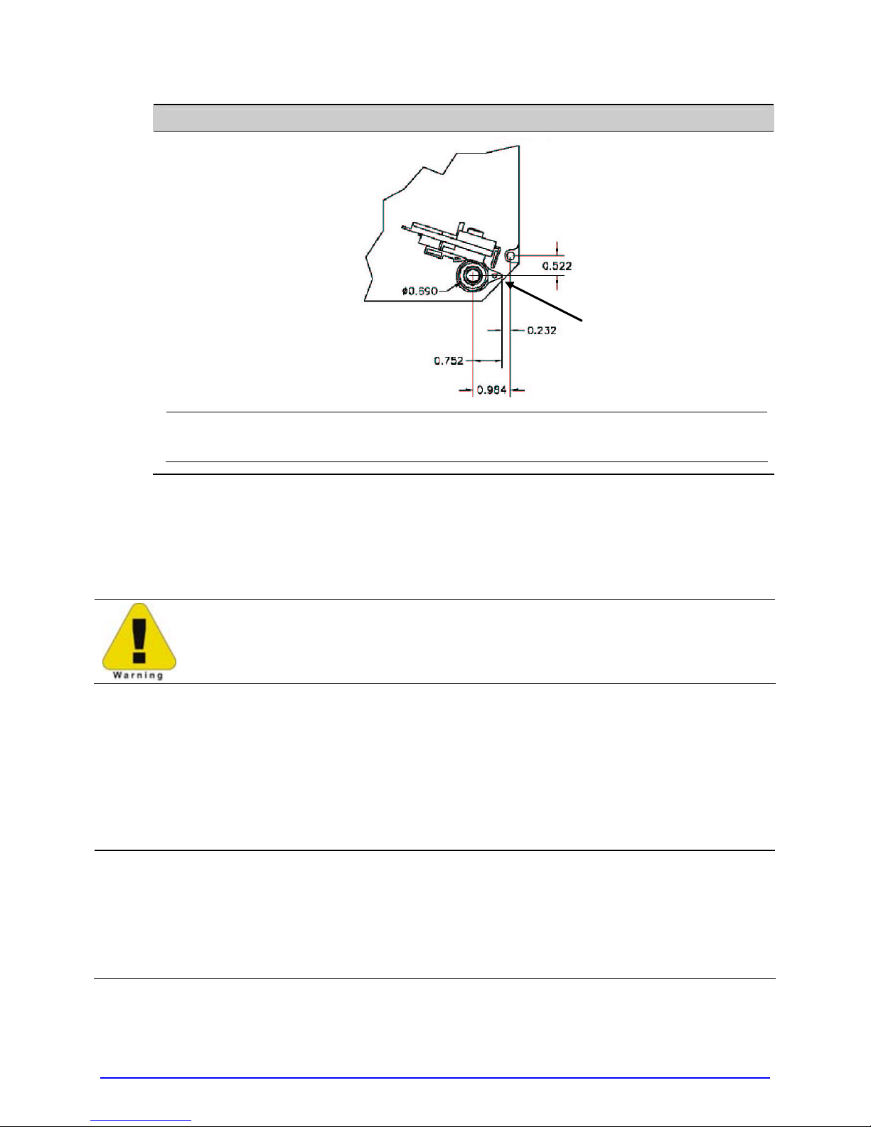
Peel Point Dimension
Peel Bar
See Appendix C for the PE printer’s dimension.
;
2.2.2 Interfacing a Host
Ensure that the Power Switch is OFF when making printer connections.
The printer can be interfaced to a host via the parallel, serial, and USB ports. (Ethernet
users, consult the documentation that accompanied the option.) Following power-up (or
after a period of inactivity), interface port selection occurs automatically upon detection of
valid data. If the incoming data flow stops and the Host Timeout period (see Section 4.2.5)
is achieved, partially received formats will be ignored and the port detection process
repeated.
The location of the following connections can vary by printer model and host
•
hardware configuration.
;
• To change an active port immediately, cycle the power OFF and ON.
• For alternate data processing options, see INPUT MODE, Section 4.2.4.
14 A-Class
Page 29

2.2.2.1 Parallel Port Connections
The parallel interface requires a Centronics
Bi-directional mode is IEEE 1284 compliant, allowing data to be returned to the host.
IEEE 1284 cable with a 36 pin male connector.
2.2.2.2 Serial Port Connections
Serial Port A supports RS-232C and RS-422/RS-485 communications; COM C and COM D
support RS-232 (see Appendix D for exceptions). Pin-outs are given below. The port baud
rate, word length, parity, stop bits, and protocol must be configured to match the host’s
settings; see Section 4.2.5.
Pin
Number
1 +5V (@ .5 amps) --2 RX RXD +
3 TX TXD –
4 DTR RXD –
5 Ground Ground
6 --- --7 RTS RTS
8 CTS CTS
9 --- TXD + ---
Port A, and COM C (J4) Port A, only COM D (J3)
RS-232 Function RS-422 & RS-485 Function RS-232 Function
+5V (@ .5 amps)
RTS
Ground
TX
RX
Ground
CTS
DTR
Port A and COM C Connections
A-Class 15
10101010
Page 30

For proper data exchange, the serial interface requires specific cable pin-outs.
Serial cable part numbers and wiring diagrams are shown below.
RS-232 Cables*
Part # 32-2300-01
*Printer serial ports A & C require a DB9 male connector (e.g., Startech C9PSM).
Part # 32-2301-01
RS-422/485 Communications
To use RS-422/485 communications (Port A, only), the main logic card must be
reconfigured:
Always wear a wrist strap and follow standard ESD prevention measures
when handling the Main Logic Card.
1. Turn OFF the power switch, unplug the AC Power Cord from the printer, and remove
any interface cable(s) already attached to the Main Logic Card.
2. Remove the two Screws securing the Main Logic Card to the printer. Slide the card
out of the printer and place it on a static free work area.
16 A-Class
Main Logic Card
Screws
Page 31

The Main Logic Card location varies depending upon the model of printer.
;
3. On the Main Logic Card, move the jumpers JMP1, JMP2, JMP3, JMP4, JMP5, and JMP6
from their positions across pins 1 & 2, and place them across pins 2 & 3,
respectively.
JMP 1
JMP 2
JMP 3
JMP 4
JMP 5
JMP 6
4. Replace the Main Logic Card and secure it using the previously removed screws.
5. Connect an RS-422/485 interface cable to Serial Port A (see the pin-out table,
above).
6. Plug in and turn ON the printer. Configure the port communication settings to match
that of the host.
COM D Port Connections
10101010
A-Class 17
Page 32
COM D RS-232 Cable
Host DB-9S Printer RJ45P
+5 VDC
GROUND
RXD
TXD
DTR
DSR
CTS
1
2
3
5
4
6
8
9
7
Part # 32-2603-00
NC
NC
NC
1
4
5
3
2
7
8
6
+5 VDC
TXD
RXD
GROUND
RTS
CTS
DTR
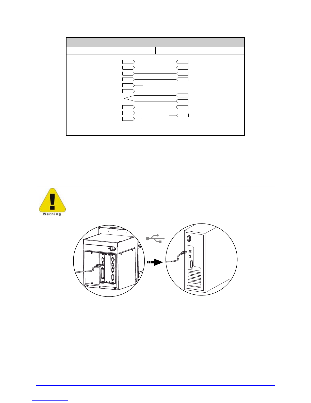
2.2.2.3 USB Port Connections
The Universal Serial Bus port requires a standard USB cable.
This USB Port is a device-end only connection. Never attach a keyboard,
mouse, modem, etc. to this port; damage can result.
18 A-Class
Page 33

2.2.3 Connecting an Applicator
Setup the GPIO Port using the information in Appendix D and then connect the applicator
cable to port(s) on the Applicator Interface Card.
Failure to properly configure the GPIO Port(s) may result in damage to the
printer and / or the applicator.
If upgrading, a PE to A-Class GPIO conversion cable is available; see Appendix C.
;
2.2.4 Connecting Power
The power cord connects to the AC receptacle on back of the printer. Make the connection
and power-up the printer as follows:
1. Ensure that AC power to the host computer and applicator system are OFF.
2. Ensure that the printer’s Power Switch is OFF.
A-Class 19
Page 34
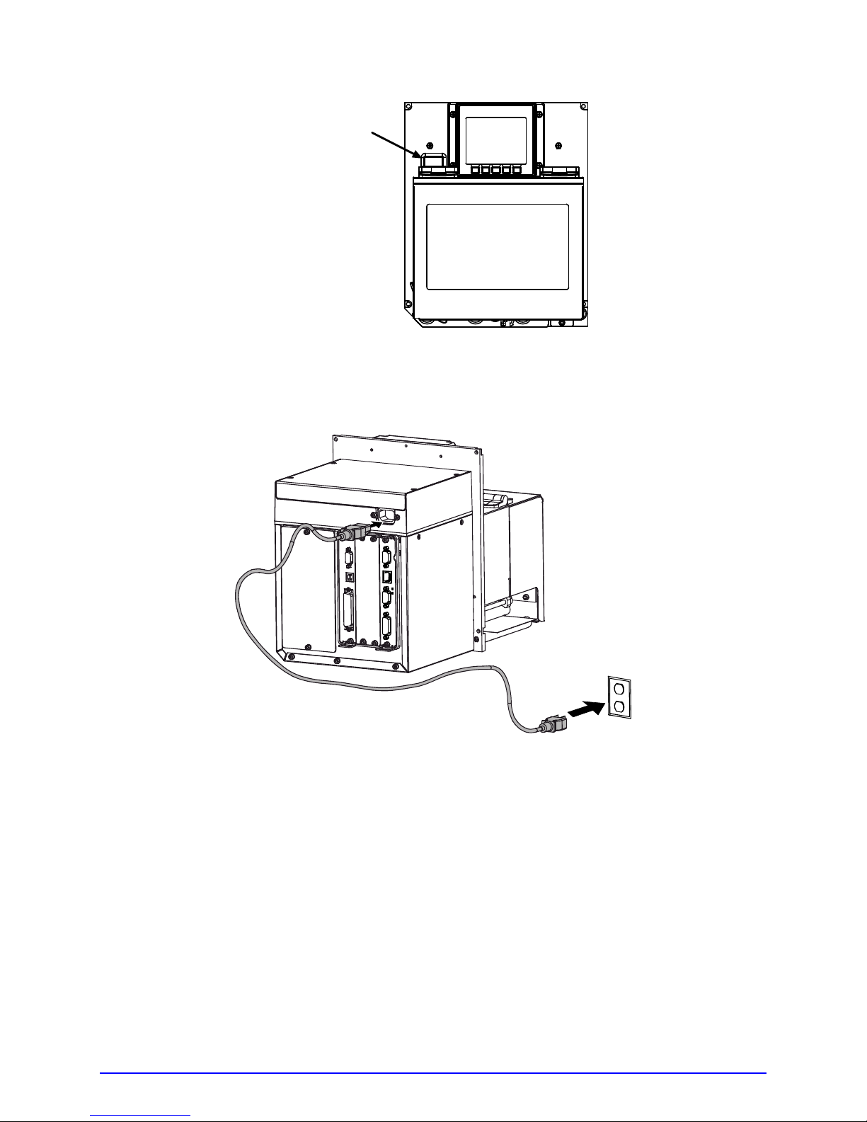
Power Switch
3. Connect the AC Power Cord to the printer and then to a properly grounded outlet.
4. Turn ON (in the following order) the host computer, the applicator system, and then the
printer.
20 A-Class
Page 35
Setting up the Printer
3
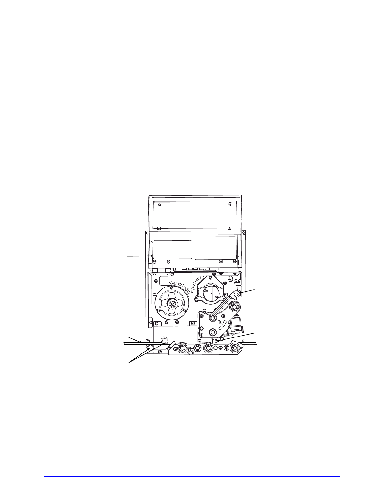
3.1 Loading Media
Load media according to its type and desired output:
1. Open the Access Cover and raise the Head Lift Lever.
2. Route the Media between the Media Posts, through the Media Sensor, over the Peel Bar,
and out of the printer, as shown below.
Access Cover
Head Lift Lever
Media
Media Posts
3. To peel die-cut labels after printing, press down on the Peel Assembly Release Lever to
lower the Peel Assembly; otherwise, proceed directly to Step 6.
Media Sensor
A-Class 21
Page 36

Peel Assembly
Release Lever
Media
Peel Assembly
4. Remove the labels from 12 inches (30 cm) of the Media Liner. Route the Media Liner
down to the Peel Assembly, over the Latch Roller, and through the Slot as shown below.
Media
22 A-Class
Media Liner
Peel Assembly
Page 37

Slot
Latch Roller
Peel Assembly
5. Pull the Media Liner through the Slot in the Peel Assembly until all slack is removed.
Lifting from the center, raise the Peel Assembly until it locks into place.
Media Guide
A-Class 23
Head Lift Lever
Peel Assembly
Page 38

6. Position the Media Guide lightly against the side of the media.
Media Guide
Head Lift Lever
Locking Post
7. Adjust the Media Sensor over t he labels (see Section 3.2).
8. If printing on thermal transfer media, load ribbon (see Section 3.3); otherwise go to
Step 9.
9. Lower the Head Lif t Lever until it is completely and securely engaged onto the L ocking
Post.
10. If loading media for the first time or if changing to a different media type or size, press
and hold the FEED Key until at least two labels have been output (see Section 3.4).
11. Adjust the Leveling Cam (see Section 5.3.1).
24 A-Class
Page 39
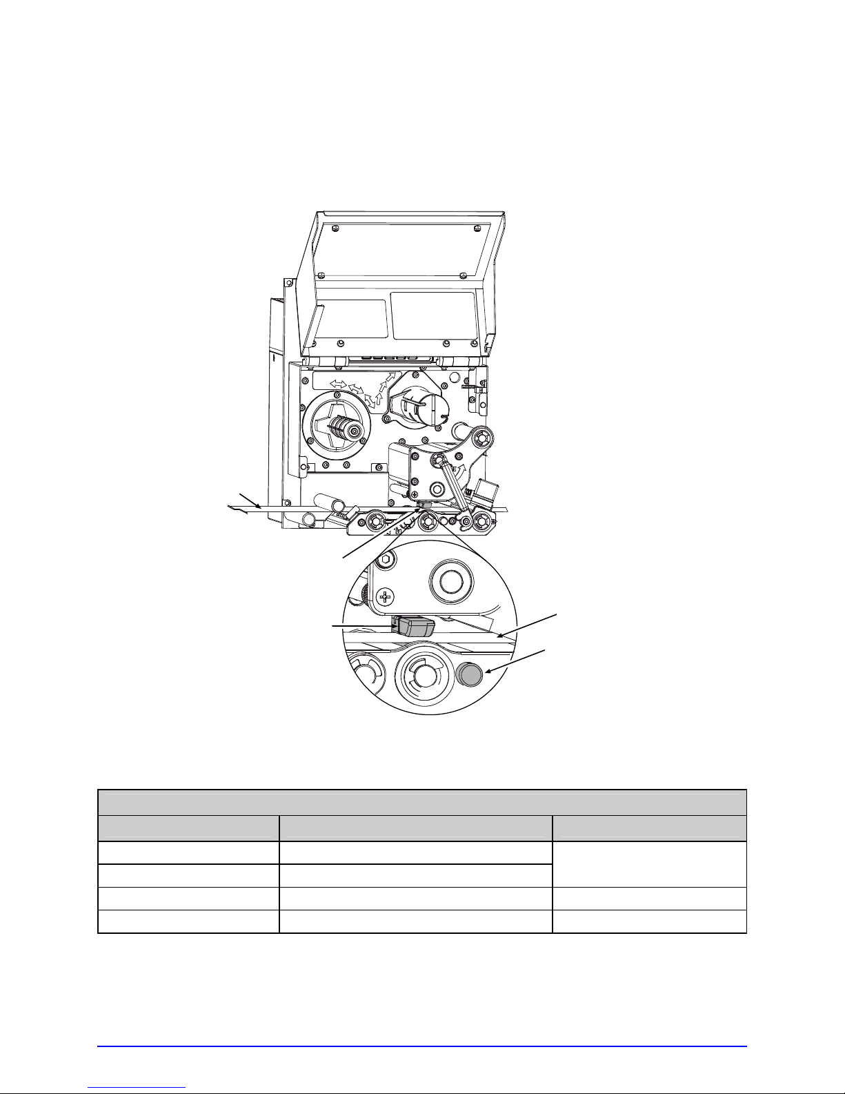
3.2 Adjusting the Media Sensor
Position the Media Sensor to detect labels as follows:
Ensure that media is routed through the Media Sensor; see Section 3.1.
1.
Media
Media Sensor
Eye Mark
Media
Media Sensor
Adjustment Knob
2. Depending on the type of media being used, rotate the Media Sensor Adjustment Knob
until the Eye Mark on the Media Sensor is positioned according to the table below.
Media Sensor Adjustment and Type Required
Media Type Eye Mark Position Sensor Type Required
Die-cut Centered over the label
Notched Centered over the notch
Reflective Centered over the black mark Reflective
Continuous Near the middle of the media Continuous
* Default setting; see Section 4.2.1.
Gap*
A-Class 25
Page 40
26 A-Class
3.3 Loading Ribbon
Load ribbon (for thermal transfer media) according to its coated side and the printer model.
;
Using a ribbon slightly wider than the media (and liner) is recommended for added protection against abrasive wear.
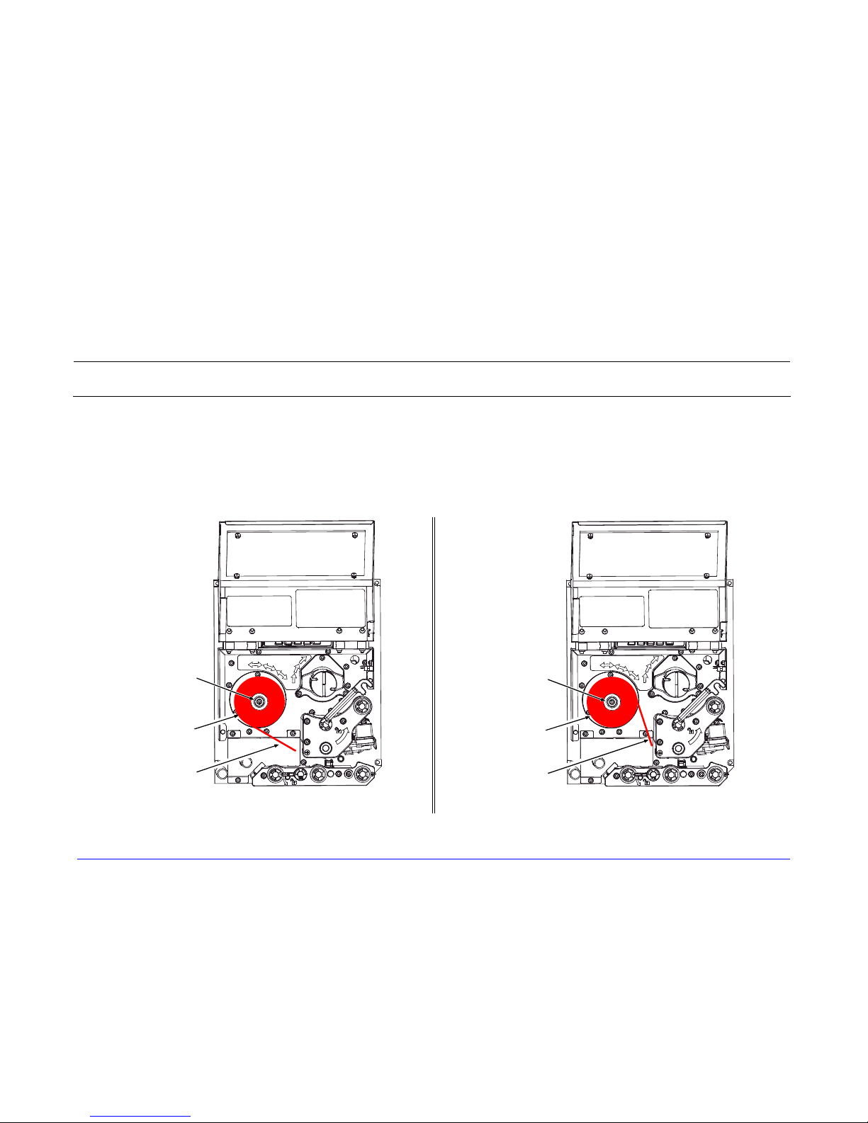
3.3.1 Right Hand Models
Load ribbon as follows:
1. Orient the unwind position of the Ribbon according to the coated side (CSI or CSO) and then slide the Ribbon Roll
completely onto the Ribbon Supply Hub, as shown below:
CSO Ribbon
Roll
Ribbon
Ribbon
Supply Hub
Ribbon
Ribbon
Supply Hub
CSI Ribbon
Roll
CSO Ribbon CSI Ribbon
Page 41
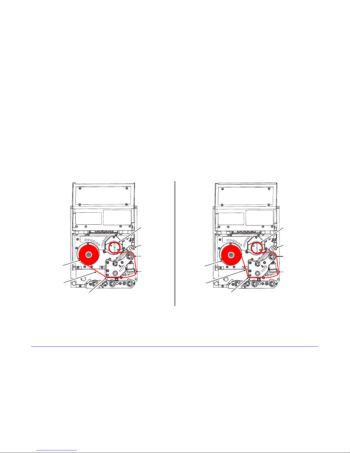
A-Class 27
2. With the Head Lift Lever raised, route the Ribbon under the Lower Idler, over the Ribbon Shield and Upper Idler, and then
clockwise around to the Ribbon Take-Up Hub.
3. Rotate the Ribbon Take-Up Hub clockwise several times to secure the Ribbon.
4. Lower and lock the Head Lift Lever then close the access cover.
CSO Ribbon
Roll
Ribbon
Ribbon
Take-Up Hub
Upper Idler
Ribbon Shield
Lower Idler
Head
Lift Lever
Ribbon
CSI Ribbon
Roll
Ribbon
Take-Up Hub
Upper Idler
Ribbon Shield
Head
Lift Lever
Lower Idler
CSO Ribbon CSI Ribbon
Page 42

28 A-Class
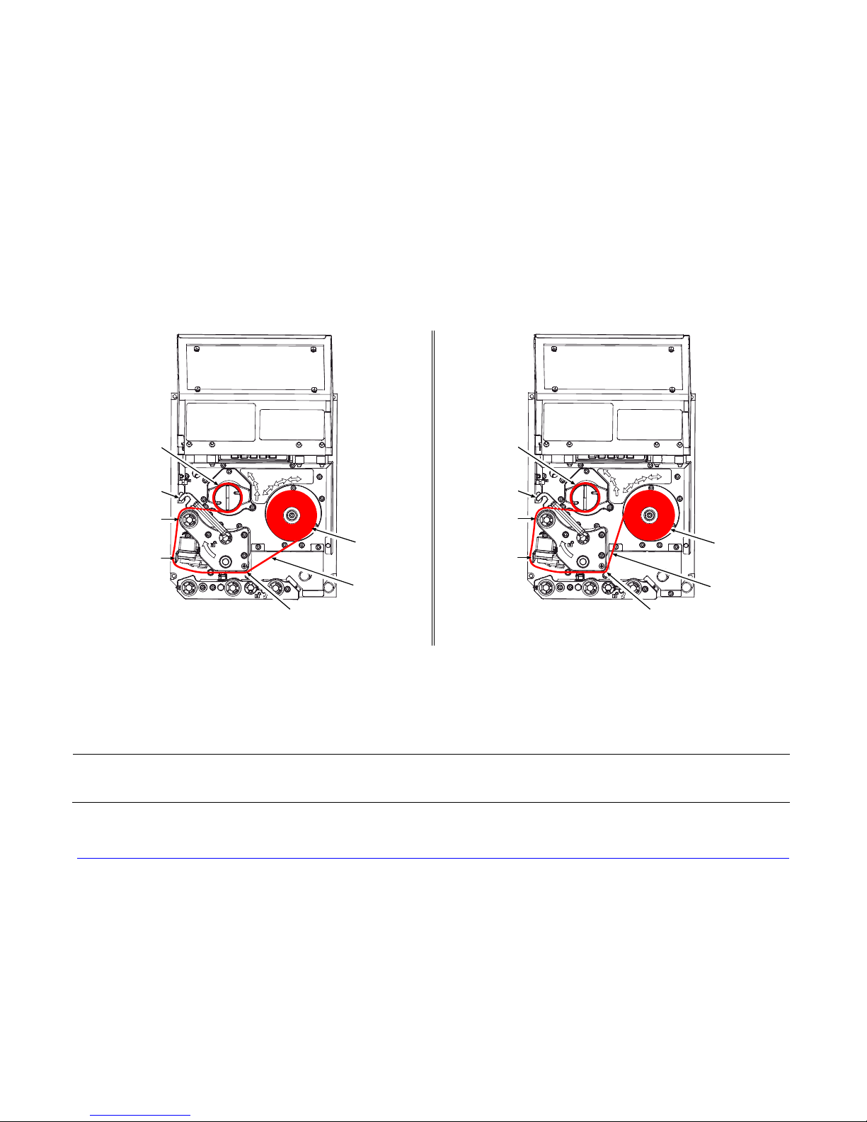
3.3.2 Left Hand Models
Load ribbon as follows:
1. Orient the unwind position of the Ribbon according to the coated side (CSI or CSO) and then slide the Ribbon Roll
completely onto the Ribbon Supply Hub, as shown below:
CSO Ribbon
Roll
Ribbon
Supply Hub
Ribbon
CSI Ribbon
Roll
Ribbon
Supply Hub
Ribbon
CSO Ribbon CSI Ribbon
2. With the Head Lift Lever raised, route the Ribbon under the Lower Idler, over the Ribbon Shield and Upper Idler, and then
counterclockwise around to the Ribbon Take-Up Hub.
3. Rotate the Ribbon Take-Up Hub counterclockwise several times to secure the Ribbon.
Page 43
A-Class 29
4. Lower and lock the Head Lift Lever then close the access cover.
Ribbon
Take-Up Hub
Upper Idler
Ribbon Shield
CSO Ribbon
Roll
Ribbon
Head
Lift Lever
Lower Idler
CSI Ribbon
Roll
Ribbon
Lower Idler
Ribbon
Take-Up Hub
Upper Idler
Ribbon Shield
Head
Lift Lever
CSO Ribbon CSI Ribbon
3.3.3 Removing Ribbon
After the ribbon supply has been exhausted, grasp the used ribbon and, while squeezing, pull to collapse the Ribbon Take-Up
Hub then slip off the ribbon. Next, slip off the empty core from the Ribbon Supply Hub.
;
If using a narrow width ribbon, it may be necessary to use one hand to pull and collapse the Ribbon Take-Up Hub,
while using your other hand to slide off the ribbon.
Page 44

3.4 Quick Calibration
Perform Quick Calibration during initial printer set-up or after changing the media, but not if
using continuous media.
Media with long gaps between labels may require a PAPER OUT DISTANCE change;
;
• With media loaded and the Media Sensor adjusted, press and hold the FEED Key until at
Calibration Hints
With some media, the sensor may have trouble differentiating between the label and liner.
If CANNOT CALIBRATE is displayed, try calibrating over a longer distance:
• Press and hold the FEED Key until the printer has output three (or more) labels.
see Section 4.2.1. Also, if UNCALIBRATED is displayed, see Section 5.2.1.
least two complete labels advance before releasing the key.
Upon successful completion, CALIBRATION COMPLETED will appear th en the printer will
feed to the next TOF and READY will be displayed. (A ‘Warnin g Low Backing’ message
may appear if using notched media or media on a transparent liner; however, the
calibration was successful).
If this method also fails (that is, if UNCALIBRATED is displayed), perform the Standard
Calibration; see Section 5.2.1.
3.5 Print Quality Controls
Flexible printing controls are provided. Of these, the amount of heat applied and the rate of
media movement will have the most effect. Four settings are available via PRINT CONTROL;
see Section 4.2.2:
• HEAT – adjust this setting to lighten or darken the print contrast;
• PRINT SPEED – adjust this setting to regulate throughput, where slow speeds allow
more time for energy transfer and fast speeds may require more HEAT to achieve the
desired contrast;
• CONTRAST – adjust this setting to fine-tune the gray (shaded) areas of the image; and,
• DARKNESS – adjust this setting to fine-tune the solid areas of the image.
Heat and Speed commands from the host software may override the printer’s menu
;
30 A-Class
setting; see HOST SETTINGS, Section 4.2.5.
Page 45

Using the Control Panel
4
4.1 Layout
The Control Panel, an event-driven user interface composed of a graphics display and
keypad, provides the following printer functions and information:
Current State Indicators
Time & Date
Printer Status
Display Window
TUE 11:55 A 04 FEB 2003
PAUSED
DATAMAX
MENU PAUSE FEED CANCEL TEST
Display Item Function
Current State
Indicators
Time & Date
Printer Status
Display Window
• COMM indicates data is being received and processed; and,
• PAUSE indicates the printer is in a paused condition.
Provides the current Time and Date setting.
Provides the READY message, a label counter when batch
printing, and any prompt, condition, warning or fault message.
Provides several types of function information:
• A start-up graphic;
• The Menu Window when in Menu Mode;
• The Test Window when in Test Mode; and,
• The FAULT message during a fault condition.
COMM
PAUSED
A-Class 31
Page 46

4.1.1 Ready Mode
In Ready Mode, when the printer is idle waiting to accept data, the Keys have the following
functions:
TUE 11:55 A 04 FEB 2003
READY
DATAMAX
Key Labels
MENU PAUSE FEED CANCEL TEST
Keys
Key Function
The MENU Key takes the printer offline and into Menu Mode; see Section
4.2. (When shaded, this denotes that security is enabled and password
MENU
entry is required; see Section 4.2.4.)
;
While in Ready Mode, pressing and holding this key will adjust
the display contrast.
PAUSE
The PAUSE Key temporarily suspends printing, as noted by the Current
State Indicators. Pressing the key again will return normal operation.
FEED
The FEED Key advances one label and clears any corrected faults. Also,
pressing and holding this key causes calibration; see Section 3.4.
CANCEL
If yes, the current job is cancelled and the printer remains paused. Also,
pressing and holding this key resets the printer; see Section 5.6.1.
The TEST Key takes the printer offline and into Test Mode; see Section
4.3. (When shaded, this denotes that security is enabled and that a
The CANCEL Key pauses operation and then prompts you for confirmation.
TEST
password must be entered to proceed; see Section 4.2.4.) Also, pressing
and holding this key evokes the printhead cleaning routine for use with
Cleaning Cards or Cleaning Film; see Section 5.5.1.
32 A-Class
Page 47

4.2 The System Menu
After the MENU Key has been pressed (Menu Mode), the Selected Menu Branch appears on
a reverse field in the Menu Window and the Keys have the following functions:
TUE 11:55 A 04 FEB 2003
OFFLINE
MENU WINDOW
Selected Menu Branch
Menu Branches
Key Labels
Keys
MEDIA SETTNGS
PR INT CONTROL
PRINT ER OPTION S
ESC ENTER
TEST
Key Function
ESC
The ESC (escape) Key exits the Selected Menu Branch. Repeatedly
pressing the key exits Menu Mode and returns the printer to Ready Mode.
The TEST Key takes the printer offline and into Test Mode; see Section
4.3. (When shaded, this denotes that security is enabled and that a
TEST
password must be entered to proceed; see Section 4.2.4.) Also, pressing
and holding this key evokes the printhead cleaning routine for use with
Cleaning Cards or Cleaning Film; see Section 5.5.1.
The DOWN ARROW Key selects the next Menu Branch. Also, in some
submenus this scrolls alphanumeric characters for filenames. (Not all
branches appear in the Menu Window at any one time.)
The UP ARROW Key selects the previous Menu Branch. Also, in some
submenus this scrolls alphanumeric characters for filenames. (Not all
branches appear in the Menu Window at any one time.)
ENTER
The ENTER Key enters the Selected Menu Branch. Also, in some
submenus this advances the cursor when entering filename characters.
A-Class 33
Page 48
The System Menu is multilayered, controlling most printer functions:
MEDIA SETTINGS
PRINT CONTROL
PRINTER OPTIONS
SYSTEM SETTINGS
COMMUNICATIONS
DIAGNOSTICS
MCL OPTIONS
•
Entering the menu takes the printer offline and halts the processing of new
data.
;
• Security prompts may appear before menu access is granted; see Section 4.2.4.
• Prompts may require confirmation before menu or printing changes are
accepted; see Section 5.1.1.
• Host computer commands may, in some cases, override menu settings; see
Section 4.2.5.
• Depending upon the firmware and options, some of the menu selections
represented below may not appear in your printer and may indicate NOT
INSTALLED when accessed.
Symbols are used in the following menu listing to define these database settings:
Symbol Definition
Setting can only be changed via the menu.
Setting is a factory default.
34 A-Class
Page 49

4.2.1 Media Settings
The Media Settings menu contains label and ribbon settings, and printhead maintenance
selections.
Menu Item Details
MEDIA TYPE
DIRECT THERMAL
THERMAL TRANSFER
SENSOR TYPE
GAP
CONTINUOUS
REFLECTIVE
LABEL LENGTH
04.00in (0-99.99)
MAXIMUM LABEL LENGTH
16.00in (0-99.99)
PAPER OUT DISTANCE
00.25in (0-99.99)
LABEL WIDTH
X.XXin (XX – X.XX)
Selects the printing method, where:
Sets printing for heat reactive media.
Sets printing for media that requires ribbon to produce
an image.
Selects the Top Of Form (TOF) sensing method used
to determine the leading edge of the label, where:
Senses the gaps or notches in the media.
Uses the LABEL LENGTH (see below) to determine the
TOF.
Senses the reflective (black) marks on the underside
of the media.
Determines the length of the label when the SENSOR
TYPE is set to CONTINUOUS, where:
Is the desired length of the format.
Sets the distance that the printer will feed GAP or
REFLECTIVE media before declaring a TOF fault,
where:
Is the length of travel to detect a TOF gap or mark.
;
This distance should be 2.5 to 3 times the length
of the label.
Sets the distance the printer will attempt to feed
media before declaring an Out Of Stock fault, where:
Is the length of travel to detect the presence of media.
;
If using transparent or translucent media, this
setting should be longer than the label’s physical
length.
Sets the maximum printable width. Objects extending
beyond this limit will NOT print, where:
Is the maximum width; see Appendix B for the model
dependant default and range.
A-Class 35
Page 50
Media Settings (continued)
Menu Item Details
RIBBON LOW OPTIONS
RIBBON LOW DIAMETER
1.40in (1.00 – 2.00)
PAUSE ON RIBBON LOW
ENABLED
DISABLED
SENSOR CALIBRATION
PERFORM CALIBRATION
ADVANCED ENTRY
SENSOR LEVELS
170 (0 – 255)
SENSOR GAIN
13 (0 – 31)
PRINTHEAD CLEANING
CLEAN HEAD SCHEDULE
000 in. (* 1000)
CLEAN HEAD COUNTER
RESET COUNTER?
YES
NO
Defines the response when THERMAL TRANSFER is
selected and the ribbon supply diminishes, where:
Sets the threshold that will trigger a Low Ribbon
Warning prompt, where:
Is the outer diameter size of the ribbon roll.
Sets the printer to pause when the Ribbon Low
Diameter setting is met, where:
Forces the user to press the PAUSE Key to proceed
with the print job.
Allows printing to continue until rib bon empty is
declared.
Selects the method that is used to calibrate the media
sensor, where:
Enters the calibration process, establishing sensor
values based on sampled readings (see Section 5.2.1).
Sets the sensor values based on an extended manual
sampling process (see Section 5.2.2), where:
Establishes the threshold.
Establishes the sensitivity.
Controls printhead cleaning alerts and functions,
where:
Specifies the inch (or centimeter) count (multiplied by
one thousand) at which to clean the printhead. If this
count is exceeded three times, a Head Cleaning Fault
will occur.
;
Zero (000) disables this function.
Indicates the number of inches (or centimeters) since
a cleaning was last initiated.
Allows the Clean Head Schedule to restart the count,
where:
Resets the CLEAN HEAD COUNTER.
Exits the menu item without changing the current
setting.
36 A-Class
Page 51

Media Settings (continued)
Menu Item Details
CLEAN HEAD NOW?
YES
Allows cleaning to begin, where:
Initiates the cleaning process when using Cleaning
Cards or Cleaning Film (see Section 5.5.1) and resets
the Clean Head Counter.
NO
Exits the menu item without cleaning.
4.2.2 Print Control
The Print Control menu contains print quality, throughput, formatting, and custom setup
functions:
Menu Item Details
HEAT
10 (0 – 30)
PRINT SPEED
XX.Xin/sec (X – XX) Is the speed setting; see Appendix B for the model
FEED SPEED
XX.Xin/sec (X – XX)
REVERSE SPEED
X.Xin/sec (X – X)
SLEW SPEED
XX.Xin/sec (X – XX)
Controls the burn-time of the printhead (selectable as
“Heat” in most labeling programs), where:
Is the number based on duration, corresponding to
print darkness.
Controls the rate of label movement during printing,
where:
dependant default and range.
;
Slower speeds may be required to print detailed
images, while faster printing may require an
increased HEAT setting for sufficient energy
transfer.
Controls the rate of label movement between printing
areas, where:
Is the speed setting; see Appendix B for the model
dependant default and range.
Controls the rate of label movement during backup
positioning, where:
Is the speed setting; see Appendix B for the default
and range.
Controls the rate of label movement between printing
areas when using the GPIO function, where:
Is the speed setting; see Appendix B for the default
and range.
A-Class 37
Page 52
Print Control (continued)
Menu Item Details
ROW OFFSET
00.00in (0 – 99.99)
COLUMN OFFSET
00.00in (0 – 99.99)
PRESENT DISTANCE Sets the label stop position, where:
0.00in (0 - 4.00)
TOF PRECEDENCE
DISABLED
ENABLED
CUSTOM ADJUSTMENTS
Shifts the vertical SOP position on the label, where:
Is the offset distance; see Section 7.1 for media
details.
Shifts the horizontal, left-justified SOP position to the
right without shifting the Label Width termination point
to the right, where:
Is the offset distance; see Section 7.1 for media
details.
Is the label travel distance at output.
Allows an override of label format data when the form
length is exceeded, where:
Prints labels formats without TOF truncating.
Ends the label at the next TOF, truncating any print
data that extends past this mark.
These selections independently change the listed
parameters, allowing slight mechanical compensations
sometimes evident when multiple printers share label
formats or for special printer-specific formatting
adjustments, where:
DARKNESS
32 (1 – 64)
CONTRAST
32 (1 – 64)
ROW ADJUST
–
XXXX (
XXX Æ XXXX)
Controls the printhead strobe time (see HEAT, above)
to fine-tune the solid areas of an image.
Fine-tunes the gray areas of an image.
Shifts the vertical SOP position to fine-tune ROW
OFFSET; see Appendix B.
;
If shifting in the negative direction, modify
PRESENT ADJUST (see below) by the same
amount.
COLUMN ADJUST
–
000 (
XXX Æ XXX)
Shifts both the horizontal SOP position and the LABEL
WIDTH termination point to the right to fine-tune
COLUMN OFFSET; see Appendix B.
PRESENT ADJUST
–
000 (
38 A-Class
XXX Æ XXX)
Adjusts the label stopping position to fine-tune
PRESENT DISTANCE; see Appendix B.
Page 53

4.2.3 Printer Options
The Printer Options menu contains module, file handling, and option functions:
Menu Item Details
MODULES
PRINT DIRECTORY Prints files present and available memory in a module.
PRINT FILE Displays a list of stored files then prints the selected
FORMAT MODULE
Controls module functions (see Appendix A), where:
(Selecting ALL will print the results from every
module.)
file image or name.
Selects from a list of modules available for formatting.
All data in the selected module will be erased.
DELETE FILE
PACK MODULE
CUTTER
MODE
AUTO
ENABLED
DISABLED
CUT BEHIND
0 (0 – 2)
Deletes a file name, preventing further access.
(Protected modules will not appear.)
Reclaims all storage space associated with the deleted
files on the specified module.
Controls the Cutter and queuing functions, where:
Sets the detection method and printer response,
where:
The presence of the cutter is automatically sensed. If
detected, the cutter is enabled; otherwise, it will be
ignored.
Enables the cutter. If the cutter is not detected, a fault
will be generated.
Disables the cutter.
Allows a number of small labels to queue before a cut
is performed, increasing throughput, where:
;
(1) Can be used without a cutter to allow the
presentation of an extra label, as retraction will not
be performed until the next job or feed.
(2) After a fault, the leading edge will be cut to
ensure material length.
Is the number of labels queued before cutting; see
Appendix A for details.
A-Class 39
Page 54

Printer Options (continued)
Menu Item Details
RIBBON SAVER
Controls the Ribbon Saver function (see Appendix G),
where:
AUTO
ENABLED
DISABLED
SCANNER
MODE
DISABLED
AUTO
ENABLED
BARCODES
CODE 39
IATA
CODABAR
INTERLEAVED 2 OF 5
INDUSTRIAL 2 OF 5
CODE 93
CODE 128
MSI/PLESSEY
EAN(13/8)
EAN(13/8)+2
EAN(13/8)+5
UPC(A/E)
UPC(A/E)+2
UPC(A/E)+5
The presence of the ribbon saver is automatically
sensed. If detected, the ribbon saver is enabled;
otherwise, it will be ignored.
Enables the ribbon saver. If the ribbon saver is not
detected, a fault will be generated.
Disables the ribbon saver.
Controls the Linear Scanner option, where:
Sets the detection method and response of the printer,
where:
Disables the option.
Detects and enables the scanner; if not detected, the
option will be ignored.
Enables the scanner; if not detected, a fault will be
generated.
Specifies the bar code type(s) for scanning, where:
;
Enabling only the types to be checked helps
maximize throughput.
Is / are the bar code type(s) checked; see the Class
Series 2 Programmer’s Manual for symbology details.
40 A-Class
Page 55
Printer Options (continued)
Menu Item Details
BARCODE COUNT
00 (0 - 99)
MIN READABLE HEIGHT
DISABLED Uses REDUNDANCY LEVEL to ensure bar code
1/16 – ½ in.
(1.5 – 12.5 mm)
REDUNDANCY LEVEL
READ BARCODE 2X
(1X – 6X)
AUTO
IGNORE NO DATA
DISABLED
ENABLED
SET DEFAULTS
YES
NO
Specifies a number of bar codes per label then
generates a fault if the number present is incorrect,
where:
Sets the number of bar codes to count, where 00
(Auto Mode) allows a variable number.
;
If bar codes are sent as bitmaps, enter the
minimum number to be read on each label.
(Check your software application for questions
regarding the bar code generation method.)
Ensures bar code integrity by setting a minimum
distance for identical decodes, where:
integrity.
Sets the read height (e.g., a setting of ¼ requires .25
inches of the bar code height be 100% readable).
;
The specified distance should not exceed 50% of
the measured bar code height.
Ensures bar code integrity by specifying a consecutive
number of identical decodes, where:
Sets the read count (e.g., a 3X setting requires three
identical decodes to pass).
;
High redundancy rates and fast print speeds may
cause erroneous read failures when scanning
small or multiple bar codes.
Uses MIN READABLE HEIGHT to ensure bar code
integrity.
Allows an override of data verification, where:
Checks for correct data in the bar code(s).
Ignores the data present in the bar code(s).
Allows the scanner default values to be restored,
where:
Restores the scanner default settings.
Exits the menu item without changing the current
settings.
A-Class 41
Page 56

Printer Options (continued)
Menu Item Details
GPIO PORT
GPIO DEVICE
DISABLED
APPLICATOR
Controls the optional Applicator Interface GPIO
function, where:
Sets the option to work with a specific device type,
where:
Disables the option.
Enables parameters for related label applicator
functions:
• Completion upon last SOP, de-asserts Data Ready
(DRDY);
• FEED allowed at any time; and,
• DRDY upon PAUSE.
APPLICATOR 2
BARCODE VERIFIER
START OF PRINT
LOW PULSE
HIGH PULSE
ACTIVE LOW
ACTIVE HIGH
EDGE
END OF PRINT
LOW PULSE
HIGH PULSE
Enables parameters for alternate label applicator
functions:
• Completion upon 1 msec. overlap of Data Ready
(DRDY) and End of Print (EOP);
• DRDY signal end inhibits FEED; and,
• De-asserts DRDY upon PAUSE or FAULT.
Enables the parameters for bar code verifier functions.
Selects the type of input signal required to initiate
printing, where:
Triggers printing with a low pulse.
Triggers printing with a high pulse.
Triggers printing with a low signal.
Triggers printing with a high signal.
Triggers printing with a signal edge transition.
Sets the type of output signal generated to indicate
EOP, where:
Outputs a low pulse upon completion.
Outputs a high pulse upon completion.
42 A-Class
Page 57

Printer Options (continued)
Menu Item Details
ACTIVE LOW
ACTIVE HIGH
RIBBON LOW
ACTIVE LOW
ACTIVE HIGH
SLEW ENABLE
STANDARD
LOW PULSE
HIGH PULSE
ACTIVE LOW
ACTIVE HIGH
ERR ON PAUSE (APP2)
ENABLE
DISABLE
RFID
RFID POSITION
1.10 in. (1.10 - 4.00) Is the inlay location, as referenced from the leading
Outputs a logic low upon completion.
Outputs a logic high upon completion.
Sets the low ribbon signal (as determined by
RIBBON LOW OPTIONS; see Section 4.2.1), where:
Outputs a logic low when the roll reaches the setting.
Outputs a logic high when the roll reaches the setting.
Selects the type of input signal required to initiate
label slew, where:
Triggers slew with a low signal.
Triggers slew with a low pulse.
Triggers slew with a high pulse.
Triggers slew with a low signal.
Triggers slew with a high signal.
Sets the output (Applicator Interface Card Type 2
equipped only) when a service required fault occurs,
where:
Enables the output signal.
Disables the output signal.
Controls the RFID operation, where:
;
If not installed (or detected), this selection will
result in a DISABLED message.
Specifies the RFID inlay position, where:
edge of the label or tag in the FEED direction.
A-Class 43
Page 58

Printer Options (continued)
Menu Item Details
TAG TYPE Selects the UHF tag type, where:
EPC 0
EPC 0+ MATRICS
EPC 0+ IMPINJ
EPC 1
EM 4022/1222
GEN 2
TAG DATA SIZE
96-BIT Sets a 96-bit data size.
64-BIT Sets a 64-bit data size.
POWER ADJUST (dBm)
000 (-04 Æ 04)
KILL CODE
00 00 00 00
ACCESS CODE
00 00 00 00
GEN 2 LOCK ACTION
NONE
PERMALOCK
PWD-READ/WRITE
BOTH
PAD/TRUNC. EPC DATA
Is the selected type.
Selects the tag data size, where:
Adjusts the applied power, where:
Is the power level, in 1.0 dBm increments.
Sets the code to permanently deactivate the tag,
where:
Is the code, in the form B3, B2, B1, B0.
Sets the code to protect tag memory contents, where:
Is the code, in the form B3, B2, B1, B0.
Sets the lock for Gen 2 tags, where:
Does not lock the tag.
Locks data permanently.
Locks data with password-protection for writing data.
Allows both Permalock and PWD-Lock to be used.
Allows padding or truncating of data with nulls
(represented as “00”) in order to fit the selected EPC
Tag Data Size, where:
DISABLED
44 A-Class
Does not pad or truncate data.
Page 59
Printer Options (continued)
Menu Item Details
LEADING
TRAILING
LOCK AFTER WRITE
ENABLED
DISABLED
RETRY ATTEMPTS Determines the number of function attempts that will
3 (0 - 9)
PERFORM CALIBRATION Allows the printer to establish the tag to transducer
YES
NO
SET DEFAULTS
YES Returns the RFID settings to default values.
NO
Adds nulls to the front (left) of the data if less than the
size, or cuts the data if greater.
Adds nulls to the end (right) of the data if less than
the size, or cuts the data if greater.
Allows the tag to be locked after programming, where:
Locks the tag.
Does not lock the tag.
be made, where:
Is the number of retry attempts.
distance and nominal power setting, where:
Initiates the process; CALIBRATING RFID will be
displayed as media is scanned for the tag location and
power, followed by TOF positioning and the results
where, if successful, the database parameters will be
updated.
No calibration occurs.
Allows the RFID settings to be restored to the factory
values, where:
Retains the current settings.
4.2.4 System Settings
The System Settings menu contains operating, control, and formatting functions:
Menu Item Details
CONFIGURATION FILE
RESTORE AS CURRENT
SAVE SETTING AS
Controls the creation, storage, and recall of printer
configuration files (see Appendix F), where:
Lists the files available and then, after selection,
reconfigures the printer according to that file.
Saves the effective printer configuration to a named
file of up to nineteen characters.
A-Class 45
Page 60

System Settings (continued)
Menu Item Details
DELETE FILE
Lists the files available and then after selection,
removes that file from memory.
;
An active file can not be deleted.
FACTORY SETTING FILE
INTERNAL MODULE D
1024 KB (XXX – XXXX KB)
DEFAULT MODULE
D
SCALEABLE FONT CACHE
Lists the files available, and then after selection that
file will be restored whenever a Level One reset (see
Section 5.6.2) is performed.
Allocates a number of 1KB memory blocks for internal
Memory Module D; where:
Is the memory allocation; see Appendix A.
Designates the storage module when no memory
location is specified; where:
Is the module; see Appendix A for availability.
Configures the number of 1KB memory blocks for the
scaleable font engine; where:
0312 (XXX – XXXX KB) Is the memory allocation; see Appendix A for
SINGLE BYTE SYMBOLS
availability.
Sets the code page used for single byte fonts, where:
PC_850 MULTILINGUAL
DOUBLE BYTE SYMBOLS
Is the selected code page. (See the Class Series 2
Programmer’s Manual for details.)
Selects the code page (see the Class Series 2
Programmer’s Manual) used for the ILPC option
(unless otherwise specified), where:
JIS
SHIFT JIS
EUC
UNICODE
GB
BIG 5
Is Japanese Industry Standard.
Is Shift Japanese Industry Standard.
Is Extended UNIX Code.
Is Unicode (including Korean).
Is Government Bureau Industry Standard, Chinese
(PRC).
Is Taiwan encoded.
46 A-Class
Page 61

System Settings (continued)
Menu Item Details
TIME AND DATE
SET HOUR
06:30AM 01JAN2008
MEDIA COUNTERS
ABSOLUTE COUNTER
RESETTABLE COUNTER
RESET COUNTER
PRINT CONFIGURATION Prin ts the current database information; see Section
CONFIGURATION LEVEL
PRINTER KEY
Sets the time and date, where:
Enters the time and date information.
Displays and controls various internal counters, where:
Are the total inches printed and the set date. (Nonresettable)
Are the inches printed and the last reset date.
Returns the RESETTABLE COUNTER to zero.
4.3.2.
Displays the hardware and software levels of the
printer, where:
;
This data is also provided on the Configuration
Label.
Identifies the unique key number of the printer, in the
form:
vvvv-cwxx-yyyyyy-zzz
Where:
vvvv
cwxx
Represents the printer model number.
Represents the hardware and software
levels, where:
A-Class 47
yyyyyy
zzz
c – Is the printer class.
w – Is the hardware level of the Main CCA.
xx – Is the software feature level:
10 = Standard DPL
20 = Internal CG Times Font
;
Increases beyond the feature level
require authorization.
Is a manufacturing date code.
Is a unique time stamp.
Page 62

System Settings (continued)
Menu Item Details
APPLICATION VERSION
BOOT LOADER
UPGRADE PRINTER CODE
0 0 0 0 0 0
UNLOCK FEATURE
0 0 0 0 0 0
SET FACTORY DEFAULTS
YES
NO
FORMAT ATTRIBUTES
TRANSPARENT
XOR
Displays the firmware program number, version, and
date.
Displays the boot loader version and date.
Upgrades the printer to the corresponding features
level with the correct code entry (where authorization
may be required).
Unlocks a feature with the correct code entry.
Returns the factory-programmed values or the Factory
Setting File values, where:
Restores the default settings, or if selected the Factory
Setting File.
;
A reset will occur and, if no Factory Setting File is
used, all settings returned except CUSTOM
ADJUSTMENTS and calibrations.
Exits the menu item without changing the current
settings.
Defines the way overlapping text, bar codes, and
graphics are printed, where:
Prints intersecting areas, for
example:
Obliterates intersecting areas, for
example:
OPAQUE
BUZZER
ENABLED
DISABLED
HEAD BIAS
48 A-Class
Overwrites intersecting areas with
those last formatted, for example:
A signaling device that sounds Control Panel
keystrokes and, where:
Signals to indicate warning and fault conditions.
Does not signal to indicate warning and fault
conditions.
Allows the dot zero orientation to flip, as viewed from
the label exit, where:
Switching this setting will reverse all media
movement directions.
Page 63

System Settings (continued)
Menu Item Details
STANDARD Sets the dot zero origin for left justified printing.
RIGHT HAND Sets the dot zero origin for right justified printing.
LABEL ROTATION
ENABLED Prints after rotating the formats 180 degrees.
DISABLED Prints the formats without rotation.
IMAGING MODE
MULTIPLE LABEL Formats multiple images, as memory permits, for the
SINGLE LABEL
PAUSE MODE
ENABLED
DISABLED
PEEL MODE
ENABLED
DISABLED
SECURITY
SELECT SECURITY
DISABLED
SECURE MENU
Allows label formats to be rotated for printing, where:
Determines the process used to format labels, where:
fastest throughput.
;
Time stamps will indicate the moment of imaging
rather than printing.
Formats an image only after a previous format has
been printed (for the most accurate time stamps).
Allows interactive print control, where:
Prints only as the PAUSE Key is pressed.
Prints normally, without user intervention.
Allows the SOP signal to initiate the feeding of labels,
where:
Feeds labels only after SOP is received.
Feeds labels regardless of SOP.
Allows menu password protection, where:
Enables or disables the security feature, where:
;
The default password must be changed to activate.
Allows open access.
Sets a password requirement for menu access.
A-Class 49
Page 64
System Settings (continued)
Menu Item Details
MENU AND TEST
MODIFY PASSWORD
YES
NO
UNITS OF MEASURE
IMPERIAL
METRIC
INPUT MODE
DPL
LINE
PL-Z
AUTO
COLUMN EMULATION
Sets a password requirement for menu and test
access.
Modifies the security password, where:
Allows entry of a four-digit password (after
confirmation).
;
The default password is 0000.
Exits the menu item without changing the current
settings.
Sets the measurement standard of the printer, where:
Uses inches.
Uses millimeters and centimeters.
Defines the type of processing that occurs when data
is received, where:
;
See the Class Series 2 Programmer’s Manual for
detailed information.
Processes data for standard DPL printing.
Processes data for Line Mode (template) printing.
Processes data for PL-Z printing.
Identifies then activates the appropriate emulation
parser for the data.
;
Correct identification can be dependant upon the
HOST SETTINGS / HOST TIMEOUT value (see
Section 4.2.5).
Also, extraneous characters
may, in some cases, render the data
unrecognizable, thus requiring manual
selection of the mode.
Allows the column dot count to be adjusted, where:
50 A-Class
Page 65

System Settings (continued)
Menu Item Details
XXX (XXX – XXX DOTS)
Is the printed number of dots per inch (or mm)
thereby reducing the width of the produced format;
see Appendix B.
;
No adjustment occurs at the default setting.
ROW EMULATION
Allows the row dot count to be adjusted, where:
XXX (XXX – XXX DOTS) Is the printed number of dots per inch (or mm)
thereby reducing or enlarging the length of the
produced format; see Appendix B.
;
No adjustment occurs at the default setting.
SOP EMULATION
DISABLED
110 (PRODPLUS)
220 (ALLEGRO)
250 (PRODIGY)
BACK AFTER PRINT
MODE
Allows SOP functions with backward compatibility
when printing legacy model label formats, where:
;
Two labels will automatically feed to establish the
selected position.
Uses the A-Class print position.
Emulates the Prodigy Plus® print position.
Emulates the Allegro® print position.
Emulates the Prodigy™ print position.
Determines media repositioning, where:
Determines initiation, where:
DISABLED
ENABLED
Moves media only when the next label is ready to
print, minimizing edge curling.
Movement occurs according to BACKUP DELAY
timing after a cut, cleared sensor, or SOP to
allow fastest throughput.
BACKUP DELAY (1/50s)
000 (0 – 255)
FONT EMULATION
Determines timing, where:
Is the specified lapse (in fiftieths of a second) between
new format processing and label retraction.
Allows font substitution, where:
A-Class 51
Page 66

System Settings (continued)
Menu Item Details
STANDARD FONTS
CG TIMES
USER ID S50
LABEL STORE
STATE & FIELDS
FIELDS ONLY
MENU LANGUAGE
ENGLISH
FRANCIAIS Enables French.
ITALIANO Enables Italian.
DEUTSCH Enables German.
ESPANOL Enables Spanish.
FAULT HANDLING
LEVEL
STANDARD
Prints using standard (internal) fonts.
Prints using CG Times font.
Prints using a downloaded font.
Determines the data content when retrieving stored
label formats, where:
Recalls the printer state (i.e., heat, speeds, etc.) and
the formatting commands for a stored label.
Recalls the formatting commands for a stored label.
Selects the language used for the menus and
Configuration Label, where:
;
Only resident languages will be selectable; see
Appendix E.
Enables English.
Determines the label disposition and user action
if a fault occurs, where:
Sets the printer response upon declaration of a
fault, where:
Stops printing and declares a fault. Then, following
correction of the problem, the FEED Key must be
pressed to clear the fault and reprint the label in
process.
52 A-Class
Page 67
System Settings (continued)
Menu Item Details
VOID AND RETRY
VOID RETRY & CONT.
DELAYED SCAN FAULT
NO REPRINT
VOID DISTANCE
Actions depend upon the RETRY COUNT:
• If the count has not been exceeded, VOID is printed
on the failed label and reprinting automatically
occurs;
• If the count has been exceeded, printing stops and
a fault message is displayed. Then, following
correction of the problem, the FEED Key must be
pressed to clear the fault and reprint the label in
process; or,
• If the CANCEL Key is pressed, reprinting is optional:
press NO to reprint; or, press YES to cancel the
reprint (and press YES again to cancel the batch.)
VOID is printed on a faulted label, with reprint
attempts occurring automatically, until the RETRY
COUNT has been exceeded and then that label will be
skipped (discarded) and printing will continue to the
next label in queue.
;
Linear Scanner or RFID required.
Increases throughput when bar codes reside near the
trailing edge of the label (in the direction of FEED).
;
• Linear Scanner or RFID required.
• If unreadable, the fault will occur after the next
label prints;
• The label immediately following a faulted label is
not scanned for errors; and,
• VOID AND RETRY and REPRINT are automatically
disabled; the job can only be cancelled.
Printing stops and a fault message is displayed. Then,
following correction of the problem, the FEED Key
must be pressed to clear the fault.
;
Linear Scanner or RFID required.
Sets the distance to print VOID on a faulted label,
where:
A-Class 53
Page 68

System Settings (continued)
Menu Item Details
0.50in (.10 to 2.00)
Is the distance, measured from the trailing edge,
which indirectly establishes the text size.
;
VOID will not be printed if insufficient label space
exists or if the fault occurred after printing
completed. Also, the text can be customized; see
the Class Series 2 Programmer’s Manual.
RETRY COUNT
1 (0 – 3)
Sets the number of printing attempts before declaring
a fault, where:
Is the count.
;
Greater than 1 (one) counts are valid only when
Linear Scanner or RFID equipped.
BACKFEED ON CLEAR
Determines positioning after a fault is cleared, where:
ENABLED
Automatically positions the label.
DISABLED
No label positioning occurs, as the location is assumed
correct.
;
If reloading, the user must place media at the
SOP position.
SCL FONT BOLD FACTOR
Sets a scalable font boldfacing amount, where:
(1 – 36)
08
Is the setting, based on an incrementing scale where
eight (08) is nominal.
4.2.5 Communications
The Communications menu contains interface port and host control functions:
Menu Item Details
SERIAL PORT A
BAUD RATE
54 A-Class
Controls the RS-232 communications settings for
Serial Port A, where:
Sets the serial communication rate, where:
Page 69

Communications (continued)
Menu Item Details
9600 BPS
115000 BPS
57600 BPS
38400 BPS
28800 BPS
19200 BPS
4800 BPS
2400 BPS
1200 BPS
PROTOCOL
BOTH
SOFTWARE
HARDWARE
NONE
PARITY
NONE
ODD
EVEN
DATA BITS
8 (7 – 8)
STOP BITS
1 (1 – 2)
SERIAL PORT B
Is the serial speed in Bits Per Second.
Sets the data flow control method (handshaking),
where:
Uses XON/XOFF and CTS/DTR.
Uses XON/XOFF.
Uses CTS/DTR.
Disables flow control.
Sets word parity, where:
Uses parity.
Uses Odd parity.
Uses Even parity.
Sets Word length, where:
Is the number of bits in the word.
Sets the stop bit count, where:
Is number of stop bits.
Controls the settings for the SERIAL PORT B when
installed, where the setting selections are the same as
those given for the SERIAL PORT A.
;
The maximum baud is 38.4K BPS.
A-Class 55
Page 70
Communications (continued)
Menu Item Details
SERIAL PORT C
SERIAL PORT D
PARALLEL PORT A
PORT DIRECTION Allows printer data to be returned to the host, where:
UNI-DIRECTIONAL Returns no data (one-way communication).
BI-DIRECTIONAL Returns data (compliant back-channel operation); see
PARALLEL PORT B
NIC ADAPTER
QUICK SETUP
Controls the settings for the Applicator Interface COM
C (J4) port, where the setting selections are the same
as those given for the SERIAL PORT A.
;
The maximum baud is 38.4K BPS.
Controls the settings for the Applicator Interface COM
D (J3) port, where the setting selections are the same
as those given for the SERIAL PORT A.
;
The maximum baud is 38.4K BPS.
Controls the communications settings for Parallel Port
A, where:
Section 2.2.2.1 for cable requirements.
Controls the settings for the PARALLEL PORT B when
installed, where the setting selections are the same as
those given for the PARALLEL PORT A.
Controls the communications settings for the network
interface, where:
;
Only when equipped with DMXNetII or DMXrfNetII.
Selects settings to configure basic Wired or WiFi
operations, where:
WIRED DHCP
NO
YES
WLAN UNSECURED
NO
YES
56 A-Class
Selects Wired operation, where:
Exits the menu item without changing the current
settings.
Returns the NIC Adapter to defaults then sets Wired
Discovery to “Enable” and Wireless to “Disable.”
Selects WiFi operation, where:
Exits the menu item without changing the current
settings.
Returns the NIC Adapter default values then sets
Discovery to “Enable,” SSID to “Any,” and WLAN
network type to “Infrastructure.”
Page 71

Communications (continued)
Menu Item Details
WLAN ADHOC
SET FACTORY DEFAULTS
WLAN
MODE
BSS ADDRESS
SIGNAL READINGS
IP ADDRESS
192.168.010.026
SUBNET MASK
255.255.255.000
NO
YES
NO
YES
ENABLED
DISABLED
000.000.000.000
Selects the DMXrfNETII default parameters, where:
Exits the menu item without changing the current
settings.
Restores WiFi defaults and initiates infrastructure
mode with an SSID of “Any.” All existing access point
associations will be deleted then established with the
closest available. (Useful when moving the printer to a
geographically distant location.)
Returns the factory-programmed values, where:
Exits the menu item without changing the current
settings.
Restores the default settings.
Controls the communications settings for the
DMXfNetII Card, where:
Selects between Wired or WiFi operation, where:
Enables the WiFi interface.
Enables the wired interface.
Specifies the static IP address of the WiFi bridge
module.
;
If DHCP is Enabled, this parameter will be ignored.
Is the address in standard octet format.
Displays the signal and noise ratios for the WLAN.
Specifies the static IP Address; where:
Is the address in standard octet format.
Specifies the static Subnet Mask Address, where:
Is the address in standard octet format.
A-Class 57
Page 72
Communications (continued)
Menu Item Details
GATEWAY
192.168.010.026 Is the address in standard octet format.
SNMPTRAP DESTINATION
000.000.000.000
IP DISCOVERY
ENABLED
DISABLED
SNMP
ENABLED
DISABLED
ADVANCED
TELNET
ENABLED
DISABLED
FTP
ENABLED
DISABLED
Specifies the network Gateway Address, where:
Specifies the SNMP Trap Address, where:
Is the address in standard octet format where SNMP
traps will be sent when SNMP service is installed on
your receiver.
;
When zeroed, no traps are sent.
Controls IP Address discovery, where:
Broadcasts over the network at startup to receive
addresses from the responsible server. Manual
modifications to IP Address, Subnet Mask, or Gateway
are not allowed; and, if no server is found, the
specified static value will be used.
A server assigned IP address takes
precedence over any static address stored
in the interface.
Uses the stored static IP, Subnet Mask, and / or
Gateway Address.
Allows management protocols, where:
Sends messages to SNMP-compliant devices.
Sends no messages.
Sets advanced networking functions and parameters,
where:
Sets Telnet protocol to transfer data, where:
Allows Telnet.
Disables Telnet.
Sets File Transfer Protocol to transfer data, where:
Allows FTP.
Disables FTP.
58 A-Class
Page 73

Communications (continued)
Menu Item Details
MTU
01500
(512 - 65515)
GRATUITOUS ARP
0000 (0 - 2048) Is the time, in minutes.
Sets the Maximum Transmission Unit packet size,
where:
Is the packet size, in bytes.
Sets the Address Resolution Protocol notification rate,
where:
PORT NUMBER
Sets the network communications port, where:
09100 (1 - 65535)
Is the Port Number.
DUPLEX CAPABILITY
AUTO-NEGOTIATE
100BASET HALF
100BASET FULL
10BASET HALF
10BASET FULL
Sets the communication capability for the Wired
network, where:
Automatically selects the best type.
Selects 100 Mbit/s half duplex (in both directions, one
way at a time) operation.
Selects 100 Mbit/s full duplex (in both directions,
simultaneously) operation.
Selects 10 Mbit/s half duplex (in both directions, one
way at a time) operation.
Selects 10 Mbit/s full duplex (in both directions,
simultaneously) operation.
ADVERTISE CAPABILITY Transmits the printer’s communication capability for
the Wired network, where:
AUTOMATIC Advertises the DUPLEX CAPABILITY set value.
ALL CAPABILITIES Advertises all possible values for DUPLEX CAPABILITY.
NETWORK REPORT
Prints a network status report (example below):
NETWORK REPORT
WED 03:15PM 23JUL2008
CURRENT PRINTER INFO
MACO: 00:0D:70:0B:8B:B9
IP ADDRESS: 192.168.10.26
SUBNET MASK: 255.255.255.0
GATEWAY: 192.168.10.26
DHCP: ENABLED
SNMP: ENABLED
PORT NUMBER: 9100
NETBIOS NAME: DMX_038BB9
WLAN MODULE
MODULE FW VERSION: 4.3.0.24
RADIO FW VERSION: 1.1.1.111.8.4.0.145
PORT STATUS: CONNECTED: ESS
SSID: 000B2802D55E
MACR: 00:0B:28:02:D5:5E
BSS ADDRESS: PROVIDED BY DHCP
A-Class 59
Page 74

Communications (continued)
Menu Item Details
SET FACTORY DEFAULTS
YES
NO
HOST SETTINGS
HOST TIMEOUT
10 SEC (1 – 60) Is the time (in seconds) when downloads timeout, and
CONTROL CODES
STANDARD CODES
ALTERNATE CODES
ALTERNATE CODES 2
CUSTOM CODES
SOH STX CR CNTBY
01 02 0D 5E
FEEDBACK CHARACTERS
ENABLED
DISABLED
Returns the factory-programmed values, where:
Restores the default settings.
;
The reset will be automatic; all settings will be
restored except CUSTOM ADJUSTMENTS and
calibrations.
Exits the menu item without changing the current
settings.
Sets host communication parameters, where:
Sets the idle period before interface port timeout
occurs, where:
that must elapse before alternate port or alternate
parser processing can occur.
Allows changes to the software command
interpretation controls, where:
Sets these interpretation codes: Hex 01 = SOH
command; Hex 02 = STX command; count-by = ^;
Hex 1B = ESC; Hex 0x0D = Carriage Return
Sets these interpretation codes: Hex 5E = SOH
command; Hex 7E = STX command; count-by = @;
Hex 1B = ESC; Hex 0x0D = Carriage Return
Sets these interpretation codes: Hex 5E = SOH
command; Hex 7E = STX command; count-by = @;
Hex 1B = ESC; Hex 0x7C = Carriage Return
Sets interpretation codes, where:
Are the codes according to your definitions.
;
Standard codes serve as default placeholders.
Allows the return of printer codes, where:
Sends the host a Hex 1E (RS) after each label and a
Hex 1F (US) after each batch successfully prints.
Sends no feedback characters.
60 A-Class
Page 75

Communications (continued)
Menu Item Details
ESC SEQUENCES
ENABLED
DISABLED
HEAT COMMAND
ENABLED
DISABLED
SPEED COMMANDS
ENABLED
DISABLED
TOF SENSING COMMANDS
ENABLED
DISABLED
SYMBOL SET COMMAND
ENABLED
DISABLED
CNTRL-CODES (DATA)
ENABLED
DISABLED
Sets handling for data containing invalid ESC
sequences, where:
Processes commands normally.
Ignores ESC control codes during processing (as some
systems send “banners” to the printer).
;
Bitmapped font downloads will be disabled.
Determines how host Heat commands are handled,
where:
Processes software commands normally.
Controls Heat via the menu setting; see Section 4.2.2.
Determines how host Print, Feed, Reverse, and Slew
commands are handled, where:
Processes software commands normally.
Controls speeds via the menu setting; see Section
4.2.2.
Determines how host Gap, Continuous, and Reflective
commands are handled, where:
Processes software commands normally.
Controls the Sensor Type via the menu setting; see
Section 4.2.2.
Determines how host Single and Double Symbol Set
commands are handled, where:
Processes software commands normally.
Controls Symbol Set selection via the menu setting;
see Section 4.2.4.
Determines how host Control Codes are handled,
where:
Processes software commands normally.
Controls the setting via the menu; see CONTROL
CODES, above.
A-Class 61
Page 76

Communications (continued)
Menu Item Details
STX-V SW SETTINGS
ENABLED
DISABLED
MAX LENGTH COMMAND
ENABLED
DISABLED
OPTION FEEDBACK
DISABLED
SCANNER
RFID HEX
RFID ASCII
PROCESS SOH (DATA)
ENABLED
DISABLED
Determines how a host option enable command is
handled, where:
Processes the command normally.
Controls the settings via the menu; see Section 4.2.3.
Determines how a host Maximum Label Length
(<STX>M) command is handled, where:
Processes the command normally.
Controls the setting via the menu; see Section 4.2.1.
Allows feedback characters from an optional device to
be returned to the host device, in the format of
<A;B;C;D;E;F>[CR], where:
A - Is the device type: R = RFID; and, S = Linear Scanner
B - Is the status: C = entire label complete; F = faulted
(failed) label; and, U = unknown
C - Is the number of expected reads, given in two
characters.
D - Is the number of good reads, given in two characters.
E - Is the internal Job and Sub Job Identifier, given in four
characters each.
F - Is the data read, delimited with semicolons (;) if
multiple reads.
Reports no data.
Reports Linear Scanner data.
Reports RFID data in hexadecimal format.
Reports RFID data in an ASCII format.
Determines the response to an Immediate Command
(e.g., Get Status, Module Storage, etc.), where:
Interrupts operations upon SOH receipt to process the
command.
Processes commands normally.
62 A-Class
Page 77

4.2.6 Diagnostics
The Diagnostics menu contains testing functions:
Menu Item Details
HEX DUMP MODE
DISABLED
ENABLED
OPTIONS TESTING
TEST CUTTER
PERFORM TEST
1 TIME
TEST RIBBON SAVER
PERFORM TEST
1 TIME
TEST GPIO
MONITOR GPIO INPUT
SOP FEED PAUSE REPRT
1 1 1 1
i1 i2 i3 i4 i5 i6
1 1 1 1 1 1
TEST GPIO OUTPUT
EP RL SR MO RO DR OF
1 1 1 1 1 1 1
o1 o2 o3 o4 o5 o6
1 1 1 1 1 1
PRINT SIGNAL INFO
Determines how the printer handles host data, where:
Processes data normally.
Prints received ASCII data without interpretation or
processing; see Section 6.2.
Performs option diagnostics, where:
Tests the Cutter, where:
Selects the number of cuts (1, 10, & 100) to perform
then displays the PASS / FAIL results.
Tests the Ribbon Saver, where:
Selects the number of cycles (1, 10, & 100) to
perform then displays the PASS / FAIL results.
Tests the Applicator Interface CCA’s GPIO function,
where:
Displays input signal logic values for Start of Print
(SOP), Feed, Pause, Reprint (REPRT), and six
unassigned input lines. (The values given here are
examples only.)
;
Unconnected lines may display a zero or one.
Displays output signal logic values for End of Print
(EP), Ribbon Low (RL), Service Required (SR), Media
Out (MO), Ribbon Out (RO), Data Ready (DR), Option
Fault (OF), and six unassigned output lines. (The
values given here are examples only.)
;
To change an output signal, cursor over the
displayed state to select and then toggle it using
the keypad, except Data Ready which cannot be
toggled.
Prints a reference label (see Appendix D) containing
GPIO signal names, pin and port assignments,
programmed settings, and current signal states.
A-Class 63
Page 78

Diagnostics (continued)
Menu Item Details
TEST SCANNER
ALIGNMENT TEST
SCAN TEST
TEST RFID
TAG DATA
DEVICE VERSION
TAG ID – HF ONLY
PRINT TEST RATE (min)
000 (0 – 120)
SENSOR READINGS
THR TRAN RIBM 24V
127 159 093 175
PS HD RANK
00 254 125
RIBBON SENSOR LIMITS
RIBBON ADC LOW
039
RIBBON ADC HIGH
250
Tests the Linear Scanner, where:
Reads a bar code then displays the decoded data, the
code type and scan count, repeating.
Reads a bar code then displays the decoded data, the
code type and scan count, non-repeating.
Tests RFID, where:
Reads the data encoded on an RFID tag.
Displays the type and version of the encoding device.
Reads then displays the High Frequency Tag ID
number.
Allows a label-to-label delay when batch printing Test
Labels, where:
Is the selected interval, in minutes.
Displays various sensor values (0 – 255), where:
Are readings for the printhead thermistor sensor
(THR), media “gap” (TRAN) or “reflective” (REFL)
sensor, ribbon sensor (RIBM), 24VDC power supply
sensor (24V), present sensor (PS), printhead assembly
sensor (HD), and printhead ranking resistor (RANK).
(The values given here are examples only.)
Displays ribbon sensor values for thermal transfer
equipped printers, where:
Are the sensor readings. (The values given here are
examples only.)
64 A-Class
Page 79

4.2.7 MCL Options
The MCL Options menu contains alternate operating selections:
Menu Item Details
MCL OPTIONS
Allows the printer to use the optional MCL (Macro
Command Language) tool suite to accept peripheral
device input data, where:
MCL AT POWER-UP
DISABLED
MCL LINK MODE
MCL PROGRAM MODE
START MCL
Allows MCL operation to begin when the printer is
turned ON, where:
MCL operation does not occur; the printer uses
standard DPL functions.
Starts MCL in Link Mode.
Starts MCL in Program Mode.
Starts MCL after exiting the menu.
When MCL is enabled, the Keys have the following functions:
TUE 11:55 A 04 FEB 2003
OFFLINE
MCL
MCL Operating Menu
System Menu
1. Run Program
Key Labels
Key Function
ESC
The ESC (Escape) Key, program dependent, typically returns to the
previous menu level.
The DOWN ARROW Key, program dependent, typically selects the next
menu item.
(continued)
A-Class 65
ESC ENTER
Keys
Page 80

Key Function
The UP ARROW Key, program dependent, typically selects the previous
menu item.
ENTER
The ENTER Key, program dependent, typically selects the current menu
item or function.
;
Consult your MCL provider for details regarding operation and support.
4.3 The Test Menu
After the TEST Key has been pressed (Test Mode), the resident Selected Test Label appears
on a reverse field in the Test Window and the Keys have the following functions:
Received data processing is disabled when testing.
If SECURITY is enabled, the password must be entered.
;
A printing delay can be set; see Print Test Rate, Section 4.2.6.
Pressing CANCEL stops printing.
TUE 11:55 A 04 FEB 2003
OFFLINE
TEST WINDOW
Selected Te st Label
Selected Test Quantity
Key La be l s
66 A-Class
Keys
PRINT QUALITY LABEL
QUANTITY 00 02
ESC SYSTEM ENTER
COUNT
Page 81
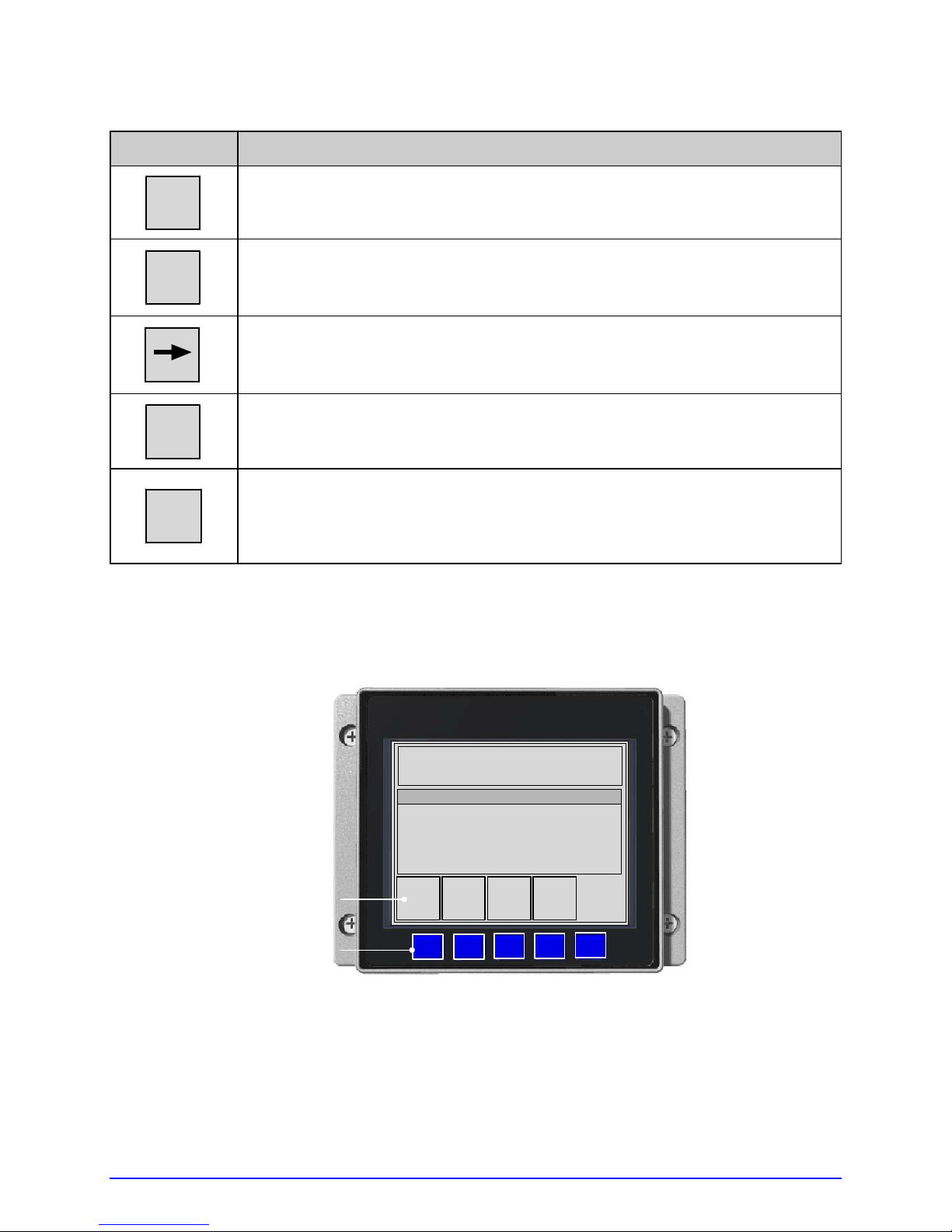
Key Function
ESC
The ESC (escape) Key exits Test Mode and returns Ready Mode.
SYSTEM
The SYSTEM Key opens a System Window (see below).
The RIGHT ARROW Key changes the Selected Test Label.
COUNT
The COUNT Key changes the Selected Test Quantity in the following
amounts: 1, 10, 100, 1000, & 9999 (except the Configuration Label).
The ENTER Key will print the Selected Test Label at the Selected Test
ENTER
Quantity using current database settings. Load full width media to capture
the entire format, or if using narrow media adjust the printer and set the
LABEL WIDTH.
Pressing the SYSTEM Key while in Test Mode provides a System Window with the following
functions:
TUE 11:55 A 04 FEB 2003
OFFLINE
SYSTEM WINDOW
DATAMAX
PAUSE
Key Labels
ESC
Keys
A-Class 67
FEED
CANCEL
Page 82

Key Function
ESC
PAUSE
The ESC (escape) Key returns Test Mode.
The PAUSE Key suspends printing. Pressing the key again will return
operation.
The FEED Key advances labels and clears any corrected faults. Also,
FEED
CANCEL
pressing and holding this key causes the printer to perform a Quick
Calibration; see Section 3.4.
The CANCEL Key suspends current operations then prompts for
confirmation; if yes, the current job is cancelled. Also, pressing and
holding this key will reset the printer and clear temporary host settings;
see Section 5.6.2.
4.3.1 Print Quality Label
The Print Quality Label serves as an overall quality
indicator. Consisting of compliant fence and ladder bar
codes, assorted font sizes, and fill patterns, this format can
be used to ensure conformance as well as aesthetics.
4.3.2 Print Configuration
Print Configuration provides current database information.
Bulleted items indicate host changes not yet saved.
;
68 A-Class
CONFIGURATION
MON 09:09AM 28JUL2008
PRINTER KEY:
6310-AC10-040623-235
APPLICATION VERSION:
83-2284-11E 11.054 07/01/2008
MCL Version: 1.20.02-126
BOOT LOADER:
83-2405-11A 11.01 10/02/2007
UNLOCKED:
*NONE
FPGA:
*
MACO:
NOT SET
MACR:
00-90-c9-01-d0-84
SYSTEM INFORMATION
PRINT BUFFER SIZE:
100 in.
FLASH SIZE:
2 MB
RAM TEST:
PASS
OPTIONAL LANGUAGES:
FRANCIAS.DLN
ITALIANO.DLN
DEUTSCH.DLN
ESPANOL.DLN
CONFI
COMMUNICATIONS
SERIAL PORT A:
BAUD RATE:
9600 BPS
PROTOCOL:
BOTH
PARITY:
NONE
DATA BITS:
8
STOP BITS:
1
SERIAL PORT B:
NOT INSTALLED
SERIAL PORT C:
NOT INSTALLED
SERIAL PORT D:
NOT INSTALLED
USB PORT:
NOT INSTALLED
PARALLEL PORT A:
PORT DIRECTION:
UNI-DIRECTIONAL
PARALLEL PORT A:
NOT INSTALLED:
Page 83
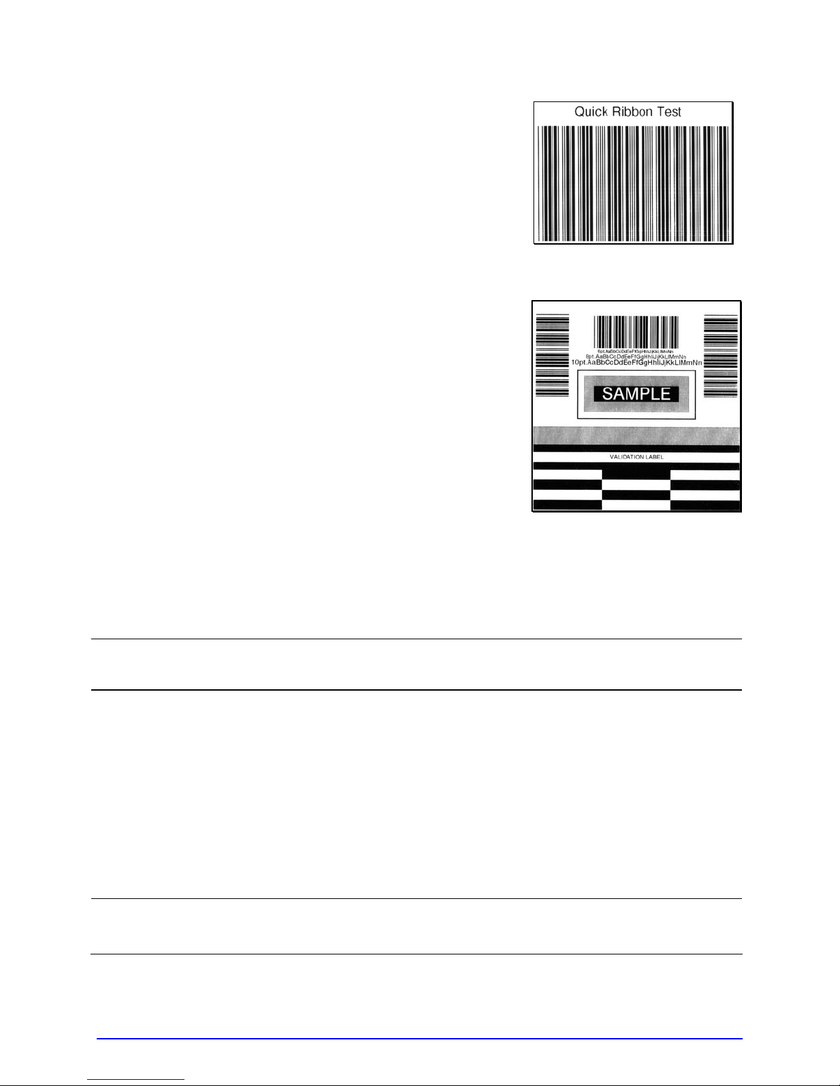
4.3.3 Ribbon Test Label
The Ribbon Test Label serves as a transfer function indicator
for printers equipped with the thermal transfer option.
Consisting of a fence-oriented bar code, this format can be
used to ensure component functions and ribbon path
alignment.
4.3.4 Validation Label
The Validation Label serves as an overall quality in dicator.
Consisting of compliant fence and ladder bar codes, assorted
font sizes, and black fill patterns, this format can be used to
ensure conformance as well as aesthetics.
4.3.5 Print Last Label
Print Last Label reprints the most recent format output by the printer.
If a job was cancelled prior to completion, or if power was removed since the last
;
print job and this label request, VOID will be printed.
4.3.6 User-Defined Label
The User-Defined Label allows a template to be populated by variable data (via the Control
Panel or a USB qwerty keyboard). The template is a stored label format, where fields
delimited by the "&" become variable. The printer will prompt the user to enter these
variable field data. (For example, the stored label format could contain the data
19131423443&ENTER NAME. Afterward, when recalled from memory, the display will
indicate the variable field: ENTER NAME.)
•
Variable data includes font ID, rotation, positioning, etc.
;
A-Class 69
• Error checking is not performed.
Page 84

70 A-Class
Page 85

Operating, Adjusting and
5
Maintaining the Printer
5.1 Displayed Messages
During operation (when not in Menu or Test Mode) the printer display s several types of
information:
• Prompts and Condition Messages (see below); and
• Fault and Warning Messages (see Section 6.1.2).
5.1.1 Prompts and Condition Messages
Prompts appear when an action is required during operation, while Condition Messages
indicate an operational state.
Prompts and Condition Messages
Displayed Message Description Action
ACCESS DENIED
BUSY…..
CALIBRATING
SENSOR LEVELS
CALIBRATION COMPLETE Calibration has finished.
CANCEL BATCH
ENTER KEY = YES!
The password used to access
the secured menu was incorrect.
The printer is performing
internal operations.
The FEED Key was pressed and
held.
The CANCEL or TEST Key was
pressed during a multiple label
job.
Enter the correct password.
Allow the operations to
complete.
Allow the calibration to
complete.
Normal operation can
resume.
Press ENTER to cancel all
remaining labels in the job.
A-Class 71
Page 86
Prompts and Condition Messages (continued)
Displayed Message Description Action
CANCEL REPRINT
ENTER KEY = YES
CLEARING FAULTS
DMXNET INITIALIZING
ENTER PASSWORD
0 - - -
INVALID ENTRY
The CANCEL or TEST Key was
pressed during a fault. (See
FAULT HANDLING / VOID AND
RETRY, Section 4.2.4.)
The FEED Key was pressed
following a fault and now the
printer is attempting to clear the
condition.
The network card is initializing,
a normal condition following
power-up or a reset.
This is the menu gateway.
An incorrect value has been
entered.
Press ENTER to cancel the
reprint.
No action is required.
No action is required.
Depending upon the
settings, it may take a few
minutes.
Enter the four-digit
password for access.
Enter a valid setting or
selection.
NOT INSTALLED
OFFLINE
PAUSED
PRINTHEAD CLEANING
READY
The selected option or feature
cannot be found.
The MENU or TEST Key was
pressed.
The PAUSE Key was pressed (or
Pause Mode is enabled, see
Section 4.2.4) and now the
printer is in a paused condition.
The TEST Key was pressed and
held, or CLEAN HEAD NOW was
selected, and now printhead
cleaning is in progress.
The printer is waiting to receive
label formats, downloads, etc.
Verify that the option or
feature is correctly installed.
If so, call for service.
Press ESC to return to
Ready Mode.
Press PAUSE.
No action is required.
Send a label format,
download, etc.
72 A-Class
Page 87

Prompts and Condition Messages (continued)
Displayed Message Description Action
REMOVE RIBBON
PRESS ANY KEY
SAVE CHANGES?
SUCCESSFUL
PRESS ANY KEY
SYSTEM INITIALIZING
SYSTEM RESET
IN PROGRESS
The TEST Key was pressed and
held, or CLEAN HEAD NOW was
selected, but ribbon is installed.
Database changes were made
that require confirmation.
The selected operation was
successfully completed.
The power switch has been
turned ON or a reset has
occurred.
A reset has occurred.
Remove ribbon and press
any key to proceed.
Press YES to accept the
changes, or NO to discard
them.
;
If required, a reset will
automatically occur.
Press any key to continue.
No action is required. Wait
briefly while the process
completes.
No action is required. Wait
briefly while the process
completes.
UNCALIBRATED
The Media Sensor is not
calibrated.
SOP signal has been received,
WAITING FOR DATA
but the printer awaits label
data.
WAITING FOR SIGNAL The printer awaits a SOP signal.
XXXX OF XXXX
PRINTING
A print job is in process, as
indicated by the batch total and
remaining label count.
Perform calibration; see
Section 5.2.
Send a format from the
host.
Send the SOP signal from
applicator to the GPIO
the
port.
No action is required.
A-Class 73
Page 88

5.2 Calibration
Calibration ensures correct media detection, and should be performed when Quick
Calibration fails (see Section 3.4).
5.2.1 Standard Method
Three calibration samples are required:
• Empty – with nothing over the sensor;
• Gap (or Mark) – with media liner, a notch, or a mark over the sensor; and,
• Paper – with the label (and liner, if any) over the sensor.
Calibrate the printer as follows:
Ensure that the correct SENSOR TYPE is selected; see Section 4.2.1.
;
Step
A Turn ON the printer.
Press the MENU Key.
Then, with MEDIA
B
SETTINGS highlighted,
press the ENTER Key.
Using the DOWN ARROW
Key, scroll to SENSOR
CALIBRATION then press
C
the ENTER Key. Press the
ENTER Key again to select
PERFORM CALIBRATION.
With no media in the
D
sensor, press the ESC Key.
Action Displayed Message Comment
CANNOT CALIBRATE
-or-
UNCALIBRATED
MEDIA SETTINGS
PERFORM CALIBRATION
REMOVE LABEL STOCK
PRESS ESC KEY <yyy>
Wait briefly for the
printer to initialize.
Press the ESC Key to
abort this procedure.
Press the ESC Key to
abort this procedure.
This sets the empty
value, where ‘yyy’
represents the current
sensor reading.
(continued)
74 A-Class
Page 89
Step
E
Action Displayed Message Comment
Proceed according to the
media type:
• Die-Cut –Remove a label
or two from the liner
then install the media.
Position the Media
Sensor under the liner
area and press the ESC
Key.
• Notched (or Reflective) –
Install media. Position
the Media Sensor under
a notch (or black mark)
and press the ESC Key.
• Continuous – Press the
ESC Key.
For die-cut media:
SCAN BACKING
PRESS ESC KEY <yyy>
- Or, for reflective media:
SCAN MARK
PRESS ESC KEY <yyy>
- Or, for continuous
media:
REMOVE LABEL STOCK
PRESS ESC KEY <yyy>
This sets the gap (or
mark) value, where ‘yyy’
represents the current
sensor reading.
;
(1) See Section 3.2 for
sensor adjustment
instructions.
(2) Do not position a
perforation over the
sensor when taking
the sample.
(3) For small notches or
reflective marks,
ensure that the labels
exit straight from the
printer.
(4) Unless otherwise
noted, do not move
the Media Sensor
after this step.
Proceed according to the
media type:
• All media except
Continuous – Position
label material (and liner,
F
if any) over the sensor
then press the ESC Key.
• Continuous – Install
media. Position the
Media Sensor under the
stock and press the ESC
Key.
(continued)
SCAN PAPER
PRESS ESC KEY <yyy>
This sets the paper
value, where ‘yyy’
represents the current
sensor reading.
;
(1) If using preprinted
media, ensure that
the area placed over
the sensor is free of
text, graphics, or
borders.
(2) See Section 3.2 for
sensor adjustment
instructions.
A-Class 75
Page 90
Step
G
H
Action Displayed Message Comment
Observe the calibration
result.
Press the ESC Key
repeatedly to exit menu
mode.
CALIBRATION COMPLETE
CALIBRATION COMPLETE
Followed by...
READY
Calibration was
successful.
;
If ‘Warning Low
Backing’ is displayed,
calibration was
successful (for
possible messages
see Section 5.1).
When calibrating gap or
reflective media, press
and hold the FEED Key
until at least one label is
output.
The printer is now ready
for use.
5.2.2 Advanced Entry
Advanced Entry will override all previous calibration settings and should only be
used when Standard Calibration attempts fail. Ensure that the correct SENSOR
;
Advanced Entry is an alternate calibration method for special-case media ty pes, where
sensor readings are taken using different sampling algorithms and from a list of these
readings the best algorithm is selected for manual entry int o the database. Follow the steps
below to perform an Advanced Entry Calibration:
Step
A Turn ON the printer.
TYPE is selected (see Section 4.2.1) before staring this procedure.
Action Displayed Message Comment
CANNOT CALIBRATE
-or-
UNCALIBRATED
Wait briefly for the printer
to initialize.
(continued)
76 A-Class
Page 91
Step
B
C
Action Displayed Message Comment
Press the MENU Key.
Then, with MEDIA
SETTINGS highlighted,
press the ENTER Key.
Using the DOWN ARROW
Key, scroll to SENSOR
CALIBRATION then press
the ENTER Key. Scroll to
ADVANCED ENTRY and
press the ENTER Key.
MEDIA SETTINGS
ADVANCED ENTRY
Press the ESC Key to
abort this procedure.
Press the ESC Key to
abort this procedure.
Scroll to SENSOR GAIN
D
then press the ENTER Key.
Place the label under the
Sensor Eye Mark and latch
the Head Lift Lever. Using
E
the DOWN ARROW Key,
scroll to GAIN TRAN 00
and press the ENTER Key.
SENSOR GAIN
GAIN TRAN
*00 (0 – 31)
<yyy>
- Or, for reflective media:
GAIN REFL
*00 (0 – 31)
<yyy>
Press the ESC Key to
abort this procedure.
• If using preprinted
labels, ensure that
the sampling area is
free of text, graphics,
and perforations.
• After ENTER is
pressed, an asterisk
(*) appears to denote
selection.
GAIN TRAN
Record the sensor reading
(‘yyy’) as a Label Value in
a table similar to the one
F
shown below, with 32
rows, four columns, and
similar headings.)
*00 (0 – 31)
<yyy>
- Or, for reflective media:
GAIN REFL
*00 (0 – 31)
The sensor reading,
where ‘yyy’ represents
the numeric sample, is
useful in locating the
best sensor position over
the media.
<yyy>
Sample Calibration Table
Gain Number Label Value TOF Value Difference Value
00 252
01
02
…
31
(continued)
A-Class 77
Page 92

Step
Action Displayed Message Comment
G
Step
Press the UP ARROW Key,
incrementing the Gain
Number by one, and then
press the ENTER Key.
Record the sensor reading
as a Label Value in the
table.
Repeat this step for each
of the remaining Gain
Numbers.
Gain Number Label Value TOF Value Difference Value
00 252
01 250
02 248
… …
31 009
Action Displayed Message Comment
Raise the printhead
assembly then proceed
according to the media
type:
• Die-cut Media –
GAIN TRAN
*01 (0 – 31)
<yyy>
- Or, for reflective media:
GAIN REFL
*01 (0 – 31)
<yyy>
Sample Calibration Table
Where ‘yyy’ represents
the current sensor
reading.
Remove a label or two
from the liner then
position the Eye Mark
over that area.
H
• Notched Media –
Position the Eye Mark
over the center of a
notch.
<yyy>
- Or, for reflective media:
<yyy>
GAIN TRAN
*31 (0 – 31)
See Section 3.2.
GAIN REFL
*31 (0 – 31)
• Reflective Media –
Position the Eye Mark
over the center of a
face-down black mark.
(continued)
78 A-Class
Page 93

Step
I
Action Displayed Message Comment
Lower and latch the Head
Lift Lever.
Using the UP or the DOWN
ARROW Key, set the Gain
Number to 00 and then
*00 (0 <yyy>
- Or, for reflective media:
press ENTER.
Record this reading as a
TOF Value for Gain
Number 00 in the table.
Gain Number Label Value TOF Value Difference Value
00 252 248
01 250
02 248
… …
31 09
*00 (0 – 31)
<yyy>
Sample Calibration Table
GAIN TRAN
GAIN REFL
31)
Where ‘yyy’ represents
the current sensor
reading.
After ENTER is pressed,
an asterisk (*) appears
to denote selection.
Step
Use the keys to increment
the Gain Number by one
and then press the ENTER
J
Key. Record the TOF Value.
Repeat this step for each
Gain Number.
(continued)
Action Displayed Message Comment
GAIN TRAN
*01 (0 -
31)
<yyy>
- Or, for reflective media:
Where ‘yyy’ represents
the current sensor
reading.
GAIN REFL
*01 (0 – 31)
<yyy>
Sample Calibration Table
Gain Number Label Value TOF Value Difference Value
00 252 248
01 250 245
02 248 234
… … …
31 09 14
A-Class 79
Page 94
Step
Action Displayed Message Comment
K
Step
In the table, where both
the Label Value and TOF
Value are at least 20,
subtract the amounts and
record the result as a
Difference Value (see
below).
Identify the largest
Difference Value and then
the corresponding Gain
GAIN TRAN
*31 (0 -
31)
<yyy>
- Or, for reflective media:
GAIN REFL
*31 (0 – 31)
<yyy>
• In this example, Gain
• This Gain Number will
Number.
Sample Calibration Table
Gain Number Label Value TOF Value Difference Value
00 252 248 4
01 250 245 5
02 248 234 14
… … … …
15 188 63 125
16 184 51 133
17 179 38 141
18 174 25 149
19 170 19 N/A
… … … …
31 132 14 N/A
Action Displayed Message Comment
Number 18 is chosen
because, where both
values are at least
twenty, it has the
highest Difference
Value.
be used to resample
the media.
Scroll to the Gain Number
determined in the
L
previous step and then
press the ENTER Key.
(continued)
80 A-Class
GAIN TRAN
*18 (0 -
31)
<yyy>
- Or, for reflective media:
GAIN REFL
*18 (0 – 31)
<yyy>
After ENTER is pressed,
an asterisk (*) appears
to denote selection.
Page 95

Step
M
Action Displayed Message Comment
Complete a table (see
example below) using
three new measurements,
as follows:
(A) Raise the printhead
assembly. Place the
label (attached to
liner) in the Media
Sensor then lower and
latch the Head Lift
Lever. Record the
sensor reading as P.
(B) Raise the printhead
assembly. Place the
liner, notch, or mark
in the Media Sensor
then lower and latch
the Head Lift Lever.
Record the sensor
reading as G (or M).
(C) Raise the printhead
assembly. Remove all
media from the Media
Sensor then lower and
latch the Head Lift
Lever. Record the
sensor reading as E.
GAIN TRAN
*18 (0 – 31)
<yyy>
- or, for reflective media:
GAIN REFL
*18 (0 – 31)
<yyy>
Where ‘yyy’ represents the
current sensor reading.
;
The re-sampled values
may differ from those
previously noted. This
is normal; do not
readjust the Media
Sensor.
Press the ESC Key and
N
then the DOWN ARROW
Key. Press the ENTER Key.
Gain Number P (Paper) G (Gap) or M (Mark) E (Empty)
18 173 42 9
(continued)
A-Class 81
SENSOR LEVELS
Selected Gain Table
The sensor readings must
now be entered into the
printer.
Page 96

Step
O
Action Displayed Message Comment
Using the DOWN ARROW
Key set the ‘Paper’ level to
the value determined in
the previous step and
press the ENTER Key.
Repeat this step for the
‘Gap’ (or ‘Mark’) and the
‘Empty’ value.
PAPER SENSOR LEVEL
P* 198 G*000 E*000
È
GAP SENSOR LEVEL
P* 198 G*084 E*000
È
EMPTY SENSOR LEVEL
P* 198 G*084 E*014
-Or, for reflective media:
PAPER SENSOR LEVEL
P* 015 G*000 E*000
È
GAP SENSOR LEVEL
P* 015 G*181 E*000
È
EMPTY SENSOR LEVEL
P* 015 G*181 E*213
The selection will change to
indicate the item for entry.
Press the ESC Key
repeatedly to exit the
P
menu and, when
prompted, save the
changes.
SAVE CHANGES?
NO YES
Selecting YES saves the
settings, while NO discards
them.
(continued)
82 A-Class
Page 97

Step
Q
Action Displayed Message Comment
Press and hold the FEED
Key until at least one label
has been output.
READY
The printer is ready for
use.
;
If the calibration
attempt fails, try
desensitizing the sensor
as follows:
Go to MEDIA SETTINGS
/ SENSOR
CALIBRATION /
ADVANCED ENTRY /
SENSOR GAIN and
lower the corresponding
GAIN SETTING by one.
Exit the menu, saving
the changes. Test the
media at the new
setting and if necessary
repeat until a usable
GAIN SETTING is
obtained.
5.3 Printhead Adjustments
To ensure consistent print quality over the wide range of media types and sizes, the printer
is equipped with a Leveling Cam and a Burn Line adjustment.
5.3.1 Leveling Cam Adjustment
When using media sizes that are less than full width of the printhead, adjust the Leveling
Cam for even pressure distribution, as follows:
If changing media sizes, readjust the Leveling Cam.
;
1. With the media loaded and the Head Lift Lever locked down, send a label format (or use
a Test format, see Section 4.3). Input a small quantity then begin printing.
A-Class 83
Page 98
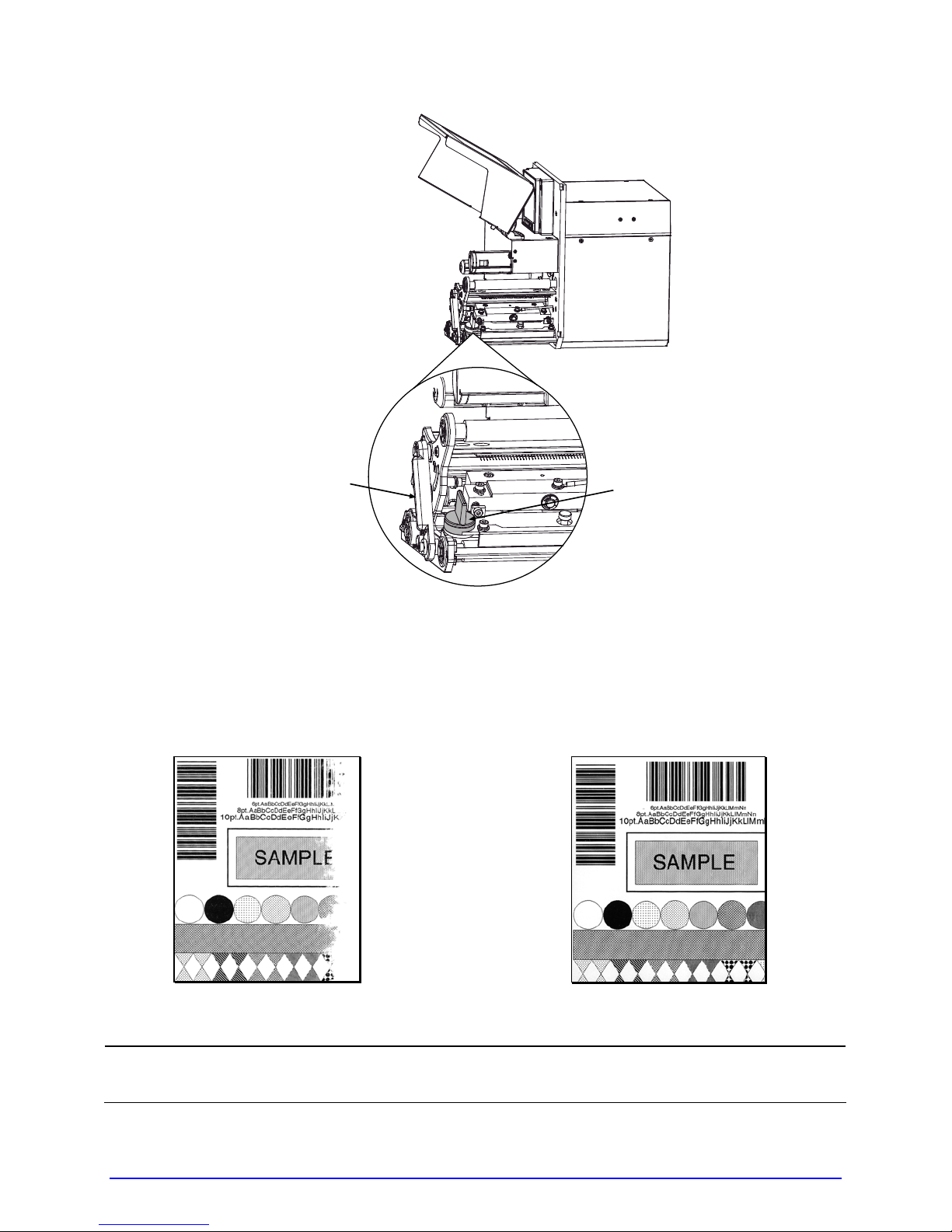
Head Lift Lever
2. While observing the printed output, rotate the Leveling Cam counterclockwise un til the
image fades across the label, as shown in Example 1 (below).
3. While observing the printed output, rotate the Leveling Cam clockwise until the image is
complete, with even contrast, as shown in Example 2 (below).
Leveling Cam
Æ
Example 1 – Over adjustment
Under-adjustment of the Leveling Cam can cause problems that include ribbon
;
84 A-Class
wrinkling, label tracking, and excessive platen and printhead wear.
Example 2 –
Correct adjustment
Page 99

5.3.2 Burn Line Adjustment
Adjust the Burn Line only after trying suggestions in Sections 5.3.1 and 3.5 to achieve print
conformance and aesthetic standards. If print quality remains unacceptable, adjust the Burn
Line as follows:
If you have questions regarding this procedure, contact a qualified technician or
;
Load media (and ribbon, if required) , as described in Section 3.1.
1.
2. Loosen the two Locking Screws on the P r inthead Assembly approximately ¼ turn
Datamax
counterclockwise.
Technical Support before proceeding.
Printhead Assembly
Locking Screws
Adjustment Screws
3. Turn the Adjustment Screws counterclockwise to bring the printhead burn line (see
illustration, Section 5.5.1) forward (in the FEED direction) of the top of the platen.
4. Print a Validat ion Label; see Section 4.3.4. (The label should have a light, uneven
appearance.)
A-Class 85
Page 100

5. Tighten the Locking Screws until ‘snug’ (that is, tight en ough to remove any play in the
printhead assembly, yet loose enough to allow the Adjustment Screws to move the
printhead).
6. Turn each
adjustments). Typically, thick media requires a slight forward adjustment, while thin
media requires a backward adjustment. Print another Validation Label and examine the
print quality. Repeat Step 6 (see note below) until labels are produced t hat meet
conformance as well as aesthetic standards.
Adjustment Screw clockwise about a ¼ turn (and 1/8 a turn for finer
When the Locking Screws are ‘snug’, turning the Adjustment Screws
;
counterclockwise will NOT move the printhead outward
adjusted too far inward, restart the entire procedure beginning at Step 2.
. If the printhead is
7. Tighten th e Lock ing Screws. Print a final Validation Label to verify the adjustment.
5.4 Printhead Replacement
• Use extreme care when handling the printhead; wear a wrist strap and
follow standard ESD prevention procedures.
• (2) If 24V OUT OF TOLERANCE is displayed (see Section 6.1.2), contact a
qualified technician or Datamax
Replace the printhead as follows:
Turn OFF the printer. Raise the Access Cover.
1.
Touch a bare metal part of the printer’s frame to discharge any static electricity that
2.
may be present on your body. Unplug the printer.
With the Printhead Assembly in the down position, loosen the Captive Screw(s). Remove
3.
the Pivot Screw and Washers that secure the Printhead Assembly. The following
drawings highlight the location of these components according to printer model:
Technical Support before proceeding.
86 A-Class
 Loading...