

Page 1

92-2366-01 Rev. D
Installation Overview
Printer Mounting Template Applicator Interface Card Connection Layout Media and Ribbon Loading
Interface Connections
Serial Port A
USB Port
Parallel Port
Power
Receptacle
COM C
GPI/O Port A
COM D
GPI/O Port B
15
14
13
12
11
10
9
8
7
6
5
4
3
2
1
J1
9
4
3
2
8
7
6
J4
1
6
11
5
4
3
2
15
14
13
12
J2
8
1
J3
1
9
8
7
Direct Thermal, Left and Right Hand
Coated Side In, Left and Right Hand
Coated Side Out, Left and Right Hand
;
Note: Depending upon the model, features, hardware options and configuration, this information will vary. Always consult the Operator’s Manual for specific printer details.
Page 2
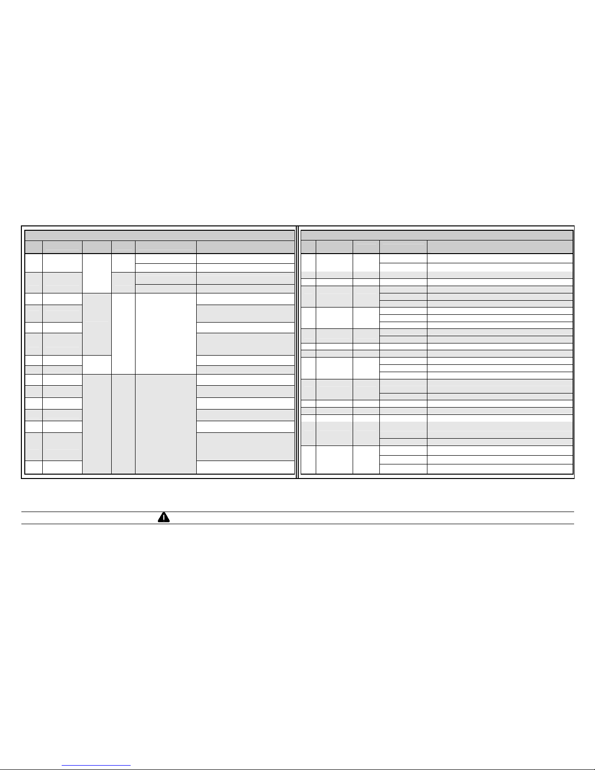
GPI/O Port A Overview
Pin
#
Signal
Signal
Direction
[1]
Jumper Position
Function /
Description
Installed Printer chassis is used.
1
Ground
JMP 8
Removed Ground must be supplied.
Installed Printer +5VDC is used (.5 amp maximum)
[4]
2 +5 VDC
N/A
JMP 9
Removed +5VDC must be supplied.
3 Start Of Print
[2]
Programmable
[3]
4 Slew Label
Advances media until the signal goes HIGH and
then, if not in continuous mode, positions at the
next available TOF.
5 Toggle / Pause Pauses the printer when LOW.
6 Reprint
Input
Reprints the last label without changes; If
always LOW, results in non-stop printing.
7 +24 VDC Printer +24 VDC (1.5 amp maximum)
8 Ground
N/A
N/A N/A
Printer chassis.
9 Ribbon Low
Programmable
[1]
. Signifies a RIBBON LOW
DIAMETER warning condition.
10 Service Required
Evoked by occurrences listed under ‘Fault
Messages.’
[1]
Active LOW.
11 End Of Print
Programmable
[1]
. Signifies the End of Print
(EOP) process.
12 Media Out
Evoked during an Out of Stock condition.
Active LOW.
13 Ribbon Out
Evoked during an Out of Ribbon condition.
Active LOW.
14 Data Ready
Evoked when a label waits to be printed. After
the Start of Print signal is received, printing
begins. (For syncing with the print cycle, the
End Of Print signal indicates print process
completion.) Active LOW.
15 Option Fault
Output JMP 1
When inactive, outputs will
be pulled up to a voltage
determined by this jumper
setting, where:
Pins 1 – 2 = +5VDC;
Pins 2 – 3 = +24VDC; or,
None = A common
external voltage (not to
exceed +30VDC) via
external pull-ups
(providing a 20K ohm
feedback path through
any two outputs).
Evoked during a Linear Scanner or RFID fault
condition. Active LOW.
GPI/O Port B Overview
Pin # Signal and
Direction
[1]
Jumper Position
Function /
Description
Installed Printer +5VDC is used (.5 amp maximum).
[4]
1
+5 VDC JMP 11
Removed +5VDC must be supplied.
2 Input 6 N/A N/A Programmed input function.
3 Input 3 N/A N/A Programmed input function.
Installed: Pins 1 – 2 Programmed output function pulled-up to +5VDC.
Installed: Pins 2 – 3 Programmed output function pulled-up to +24VDC.
4 Output 6 JMP 7
Removed Determined by an external source and pull-ups, not exceed +30VDC.
Installed: Pins 1 – 2 Programmed output function pulled-up to +5VDC.
Installed: Pins 2 – 3 Programmed output function pulled-up to +24VDC.
5 Output 3 JMP 4
Removed Determined by an external source and pull-ups, not exceed +30VDC.
Installed Printer chassis is used.
6 Ground JMP 10
Removed Ground must be supplied.
7 Input 5 N/A N/A Programmed input function.
8 Input 2 N/A N/A Programmed input function.
Installed: Pins 1 – 2 Programmed output function pulled-up to +5VDC.
Installed: Pins 2 – 3 Programmed output function pulled-up to +24VDC.
9 Output 5 JMP 6
Removed Determined by an external source and pull-ups, not exceed +30VDC.
Installed: Pins 1 – 2 Programmed output function pulled-up to +5VDC.
Installed: Pins 2 – 3 Programmed output function pulled-up to +24VDC.
10 Output 2 JMP 3
Removed Determined by an external source and pull-ups, not exceed +30VDC.
11 +24 VDC N/A N/A Printer +24 VDC (1.5 amp maximum).
12 Input 4 N/A N/A Programmed input function.
13 Input 1 N/A N/A Programmed input function.
Installed: Pins 1 – 2 Programmed output function pulled-up to +5VDC.
Installed: Pins 2 – 3 Programmed output function pulled-up to +24VDC.
14 Output 4 JMP 5
Removed Determined by an external source and pull-ups, not exceed +30VDC.
Installed: Pins 1 – 2 Programmed output function pulled-up to +5VDC.
Installed: Pins 2 – 3 Programmed output function pulled-up to +24VDC.
15 Output 1 JMP 2
Removed Determined by an external source and pull-ups, not exceed +30VDC.
[1]
Signal directions are given relative to the printer.
[2]
If active with no current print job, “WAITING FOR DATA” will be displayed. Specifying a quantity of 9999 while keeping this signal ON will cause non-stop label printing, except in single label “Imaging Mode”, which will cause the printer to stop between labels.
[3]
For setting details, see PRINTER OPTIONS / GPIO PORT.
[4]
Drawing more than .5 amps can cause unreliable printer operation.
WARNING: Failure to properly configure the GPIO Port jumper settings may result in damage to the printer and / or applicator.
 Loading...