

Page 1
HF and UHF RFID Modules
Installation and Operating Instructions
92-xxxx-01 Rev. A
Corporate Headquarters
4501 Parkway Commerce Blvd.
Orlando, Fl 32808
Phone: 407-578-8007
Fax: 407-578-8377
Asia-Pacific
Loyang Way
19
#01-01 Changi Logistics Centre
Singapore 508724
Phone: +65 542-2611
Fax: +65 542-3611
Datamax International
Herbert House
12 Elizabeth Way, Pinnacles
Harlow, Essex CM19 5FE UK
Phone: +44 1279 772200
Fax: +44 1279 424448
Printed U.S.A. Copyright 2004
Page 2

Page 3
Note: This equipment has been tested and found to comply with the limits for a Class A digital device,
pursuant to part15 of the FCC Rules. These limits are designed to provide reasonable protection against
harmful interference when the equipment is operated in a commercial environment. This equipment
generates, uses, and can radiate radio frequency energy and, if not installed and used in accordance with
the instruction manual, may cause harmful interference to radio communications. Operation of this
equipment in a residential area is likely to cause harmful interference in which case the user will be
required to correct the interference at his own expense.
CAUTION: This device complies with FCC Radio Frequency exposure limits for an uncontrolled environment.
This equipment should be installed and operated with a minimum distance of 20cm between the
radiator and your body. If 20cm distance cannot be maintained, end users are to be 20cm from
printer extremity.
CAUTION: Any changes or modifications to this RFID module not expressly approved by Datamax Corporation
will void the user’s authority to operate the equipment.
Firmware Required
This option requires Application Version ‘8.04’ or greater to operate.
Preparing the Printer
Start this installation by ensuring that the printer has the correct Application Version as follows:
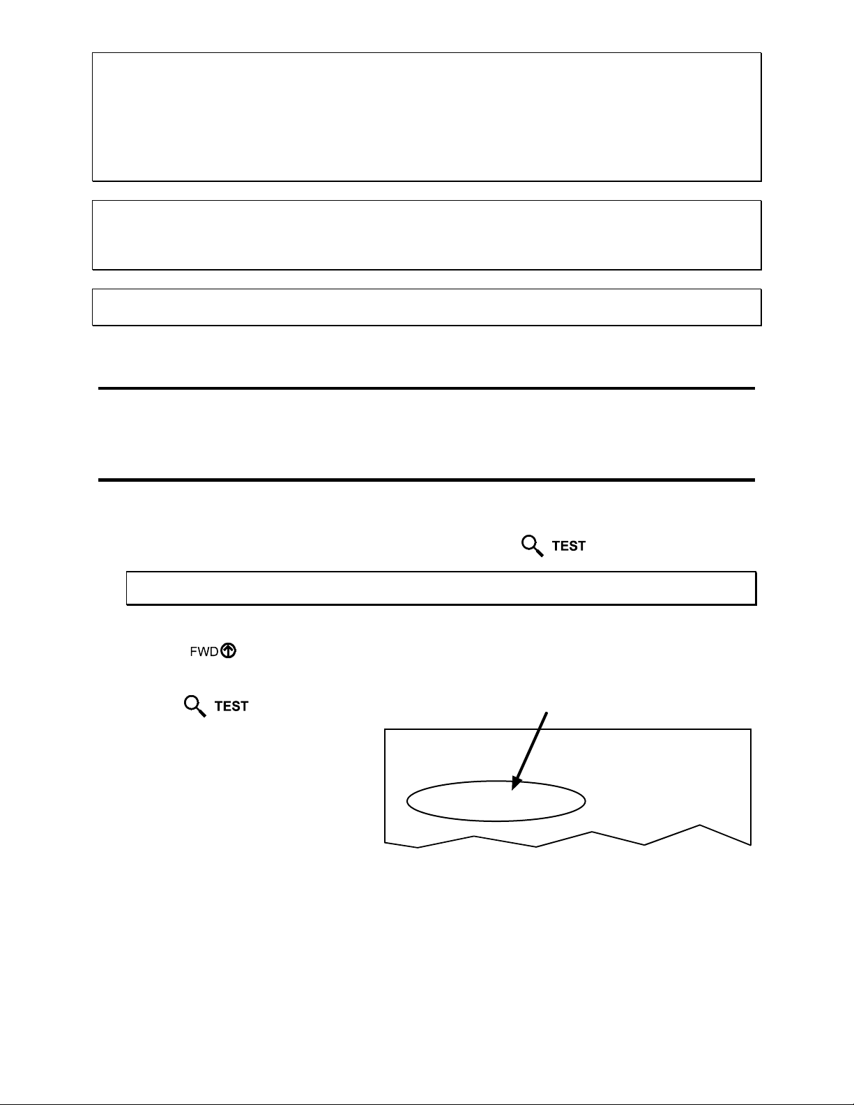
1. With the printer powered ‘On’ and loaded with media, press the
;
Note: To capture all of the printed information, use 2-inch (51 mm) or wider media, with a Label Width
setting that is matched to the label’s width. See the Operator’s Manual for details.
2. Using the
Key, scroll to Print Configuration.
3. Press the
Key.
4. Examine the Application Version
printed on the label. Compare that
number with the example, shown right.
Ensure that the Application Version is
at a level of 08.03, or greater.
CONFIGURATION
DATE NOT SET
PRINTER KEY:
4208-PA99-000412-488
APPLICATION VERSION:
83-2368-07ZN1 07.26 CP 09/19/2003
BOOT LOADER:
83-2268-02M 03.04 10/31/2000
5. If necessary, update the Application Version by downloading the firmware file for your model printer
from ftp://ftp.datamaxcorp.com/anonymous/temp/rfid/ then follow the “Updating Printer
Firmware” procedure found in the Operator’s Manual.
Key.
SYSTEM SETTINGS
INTERNAL MODULE
1024
SCALABEL FONT CACHE
232
SYMBOL SET
DATAMAX
ABSOLUTE COUNTERS
0 inches
DATE NOT SET
RESETTABLE COUNTERS
Page 4
Installing the Option
Follow the steps below if installing the RFID module. If the RFID module is already installed proceed to
the next section.
1. Turn off the power switch and unplug the
printer.
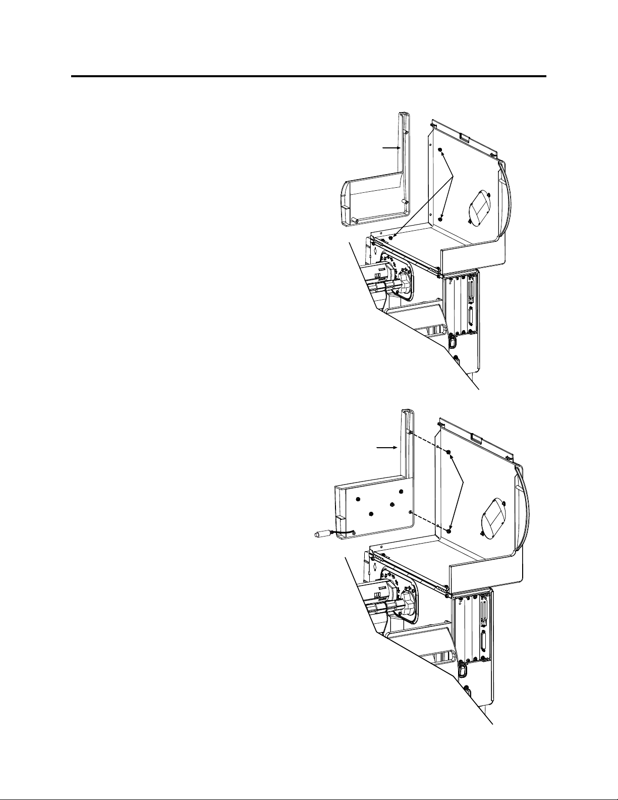
2. Open the cover and remove the three Screws
that secure the Front Cover Panel to the
printer.
Front Cover
Panel
Screws
3. Position the RFID Front Cover Panel on the
printer and re-install two of the previously
removed screws, as shown.
RFID Front
Cover Panel
Screws
Page 5
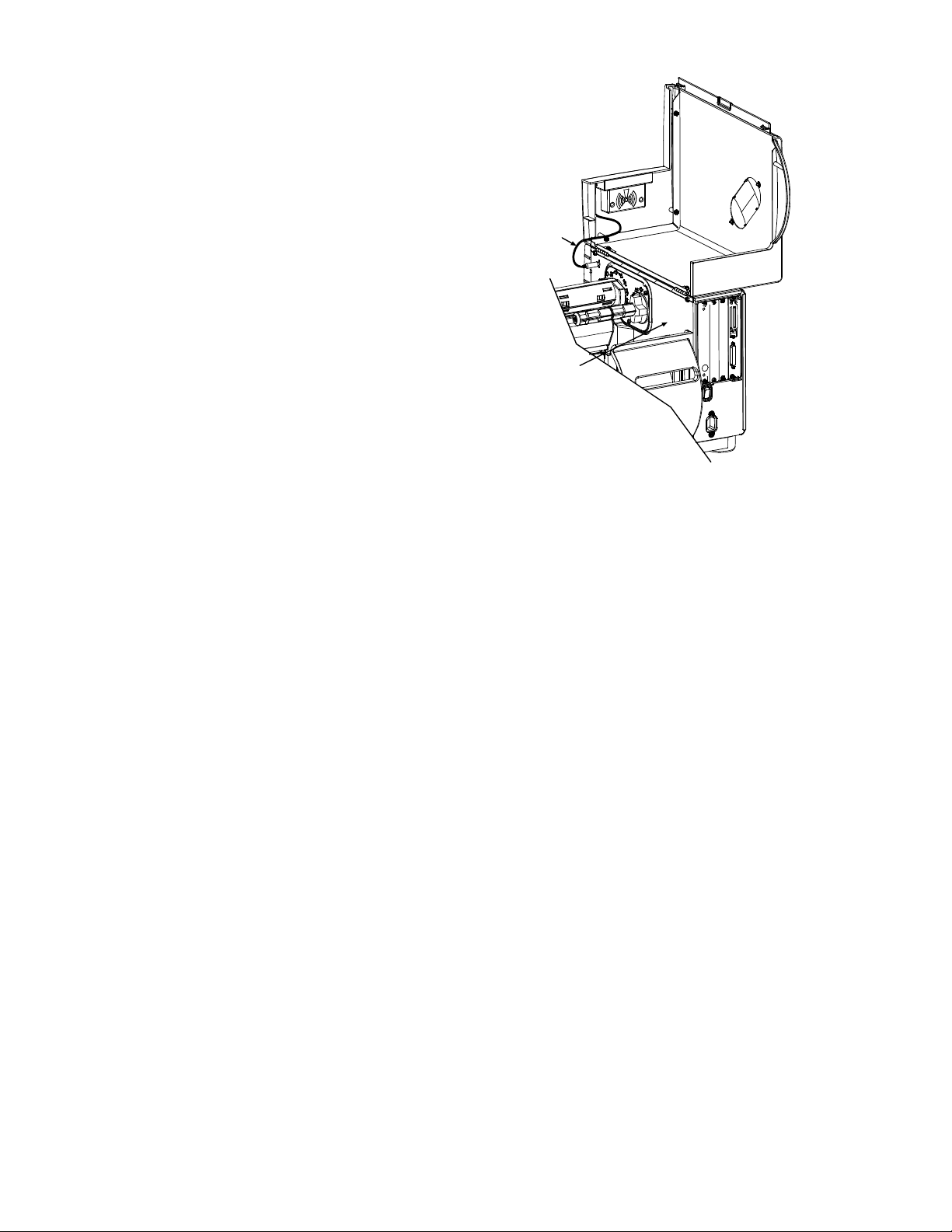
4. Route the RFID Cable as shown.
5. Connect the RFID Cable to the connector in
the printer’s Centerplate.
This completes the installation. Load Smart
labels and ribbon (if necessary) then close the
printer’s cover.
RFID
Cable
Centerplate
Page 6
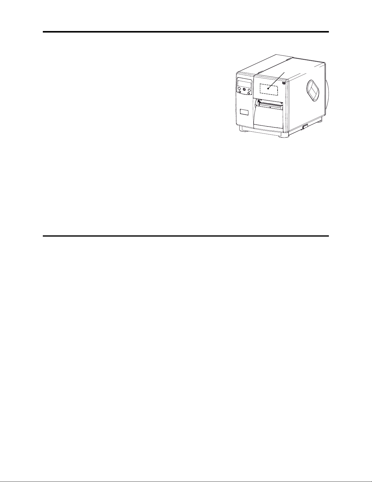
RFID Programming Information
The RFID option uses a programming device with antenna mounted
just after the print head. The device is attached to the cover and thus
the cover should be down for all printing applications. The RFID
module will be auto-detected at power-up
There are 2 different modules currently supported. The first is the
HF (13.56mhz) by SecuraKey, capable of encoding data into
standard ISO 15693 tags, which have four bytes of data per block
with the number of blocks different for each manufacturer. Texas
Instrument RFID stock contains 64 writable blocks while Philips
contains 28 writable blocks, ST Micro LRI S12 contains 16 writable
blocks.
The second is the UHF (915Mhz) by Alien, capable of encoding data
into Alien Class 1 EPC tags. These contain 64 or 96 bits of user
programmable data.
This section provides details of the Datamax DPL commands necessary to enable, configure, read, write,
and verify RFID tags. It is divided into the following sections: Initialization, Database/Menu, Data Input,
Interfaces, Data Output, and Diagnostics. This document also provides information pertaining to the
scanner option related to the data read and number of valid or defective scans (good or bad barcodes).
.
RFID
Module/Antenna
Initialization
The initialization interface to the optional RFID module is auto baud detectable. If the option is enabled
or the COM2 interface has the option selected (jumper settings on selective I/O) the firmware will query
the module by sending a unique request for info from the module (i.e. version string/firmware revision
request) on various supported Baud Rates to determine if the module exists.
Page 7

Database / Menu
Database and Menu Selection will be constructed to support the following system level data.
The following resides on the operator’s front panel menu under “PRINTER OPTIONS” → “RFID”.
Upon selection the display will show “NOT INSTALLED” if the device is not equipped or not
communicating and then proceed to the Mode selection.
RFID
MODE D
POSITION 0.00 - 4.00.
HF SETTINGS
AFI VALUE 2 Char Hex Value (Industry Codes)
AFI LOCK E
DFSID VALUE 2 Char Hex Value (Industry Codes)
DFSID LOCK E
EAS VALUE 2 Char Hex Value (Mfg. Codes)
UHF SETTINGS
LOCK CODE 2 Char Hex Value
LOCK AFTER WRITE E
ERASE ON FAULT E
RETRY ATTEMPTS 0 -> 9
AUTO DETECT TAG Moves label to find tag.
AFI - Application Family Identifier
DFSID - Data Storage Format Identifier
EAS - Electronic Article Surveillance
The following resides on the operator’s front panel menu under “COMMUNICATIONS” → “HOST
SETTINGS” → “OPTION FEEDBACK”.
OPTION FEEDBACK D
ISABLE, UHF (915mhz), HF(13.56mhz)
Currently if value is 0.00 print
position is used to encode tag. If > 0.00
presented position is used.(Subject to
change.)
NABLE or DISABLE
NABLE or DISABLE
NABLE or DISABLE
NABLE or DISABLE
ISABLE, RFID, ASCII, HEX, SCANNER
Page 8

Data Input
The input data is in the form of new System and Label Formatting commands. The system level commands consist
of Database and Direct User Interface.
Database setup commands <STX>KcRI and response data <STX>KcQQQ support the entries that are shown in the
Operator’s Menu interface.
STX KcRIa
RFID Configuration
(RF) RFID Configuration – This command configures the optional RFID interface module as follows:
Value Range / Interpretation
M, A, D, S, L,
R, W, E, P
RI
Mn - Mode (enables RFID module detection by the printer):
Where n is:
D - disabled (RFID disabled); N is also a valid disabler
U - UHF (915mhz)
H - HF (13.56mhz)
(HF) - Ahhl - Application Family Identifier (AFI); where hh is 2 Char Hex ID & l is Lock after
write (E-Enable /D-Disable)
(HF) - Dhhl - Data Storage Format Identifier (DSFID); where hh is 2 Char Hex ID & l is Lock
after write (E-Enable /D-Disable)
(HF) - Shh - Electronic Article Surveillance (EAS) Set; where hh is 2 Char Hex ID representing
manufacturers code
(UHF) - Lhh – Lock Code; where hh is 2 Char Hex ID
Rn - Number of retries (n = 0 to 9)
Wn – Lock after write; where n is: (E-Enable /D-Disable)
En – Erase (erase tag) on error; where n is: (E-Enable /D-Disable).
Pxxx - Position. Currently if value is 0.00 print position is used to encode tag. If > 0.00
presented position is used.(Subject to change.)
Example: <STX>KcRIMH;RIA11E;RID22E;RIS04;RIR3;RIWE;RIEE;RIP000<CR>
The above example sets the printer to HF, protect after write AFI 11, protect after write DFSID 22, set EAS Bit
(Mfg. Code 0x04), allow 3 tries for each read or write attempt, lock after write and erase the tag if there is an error
and position of 0.00.
STX KcOFa
Option FeedBack
OF
(OF) Option Feedback Mode – This command configures the printer to output the status of the RFID
operation to the current port. See Data Output section for details of the response.
Value Range / Interpretation
D, Rx, S
D - Disable
R - RFID Enable, where x = A - ASCII Response, x = H - Hexadecimal response
S - Scanner Enable
M, A, D, S,
See Table Below. Printer Options
L, R, W, E, P
RFID Configuration Set Commands
D, Rx, S See Table Below. Printer Options
Page 9

Interfaces
The printer has two modes of operation for programming the RFID tags: Direct and Label Formatting
Mode.
The Direct Mode allows the User (Host) to control the reading and writing of the RFID Tag directly.
Each RFID tag is individually processed with status and data responses. This mode contains both a
generic Read/Write Interface or High Level Tag HF or UHF specific interface.
The Label Formatting Mode utilizes the current printer configuration to process all the reads, write, and
exception processing, (for exception processing and fault handeling see the Operator’s Manual) for each
tag printed. The specification for the RFID operation is contained in the data fields of a DPL label
format. The label format instructs the printer to write data, read data
printing the label. It supports auto increment and decrement commands (+/-). NOTE: Currently only one
RFID operation per label is allowed.
The RFID Programming Data can be entered in one of two different formats: ASCII and Hexadecimal.
The ASCII format is entered as you would normally see it, i. e 'DATA'. The Hexadecimal format is
entered as the hexadecimal equivalent of the ASCII, i.e DATA becomes '44415441'. When entering byte
counts you must take into account the data format you are entering it in. For ASCII mode 'DATA' has a
byte count of 4. For hexadecimal mode '44415441' has a byte count of 8.
and update selective fields prior to
Page 10

Direct Mode - Generic Read/Write Interface
This interface allows the Host Application to send generic commands for RFID operations. These
commands consist of simple read and write operations requiring no knowledge (except data format) of the
tag types being used. They utilize the printer’s database for specific parameters.
STX KaW Write Data to RFID Tag
This command instructs the RFID device to write data to the tag. It is expected that the tag transponder is
within read/write distance of the RFID programming device otherwise a fault will occur and a warning
message will be displayed.
Syntax: <STX>KaWAaaabbbbcddd…
Where: Aaaa - Optional – for data in ASCII format followed by byte count,
000-999
bbb - HF- Starting block number, (000 -> Max block number)*
UHF – Should be 000.
c - Command 1. Reserved for Future (should be 0)
d - Command 2. Reserved for Future (should be 0)
eee - Data to be encoded on RFID tag. (HF - Last used block will be
null padded if necessary)
Sample: <STX>KaW0000054455354[CR]
This example programs the data “TEST” at block zero
*Dependent on transponder manufacturer.
Page 11

STX KaR Read Data from RFID Tag
This command instructs the RFID device to read data from the tag and put it in a replaceable field. It is
expected that the tag transponder is within read/write distance of the RFID programming device otherwise
a “Void” will print in the text or barcode label fields.
Syntax: <STX>KaRAaaabbbcdee
Where: A - Optional – for data in ASCII format
aaa - Bytes to read.
c - Command 1. Reserved. Should be 0.
d - Command 2. Reserved. Should be 0.
Sample: <STX>L
This example creates a replaceable text field, 01, and recalls data from the RFID tag block zero,
reading only one block, and prints the data in the location specified by replaceable field. Since there
are two digits per hex value replaceable fields should be twice as long as if using ASCII data. For
example, the character “A” would be returned as “41”.
*Dependent on transponder manufacturer.
bbb - HF - Starting block number, (000 ->Max block number)*
UHF – Should be 000.
ee - Field number where to place data. Must be 01, 02, 03, etc…
matching the order of label formatting command U.
Note: a 00 value will send read data to host with no printing.
1911A1802000010TEXT
U
X
<STX>KaR0000010001
<STX>G
Page 12

Direct Mode - HF (13.56mhz) ISO15693 Tag Interface
This interface allows the Host Application to perform specific operations pertaining to HF type tags.
These commands override the printer database as they interface directly to the tag module. Knowledge of
HF tags and their operation is required.
STX KtW Write Data to RFID Tag
This command instructs the RFID device to write data to the tag. It is expected that the tag transponder is
within read/write distance of the RFID programming device otherwise a fault will occur and warning
message will be displayed.
Syntax: <STX>KtWBnnnaaabcdeeee…
Where: Bnnn
(Optional)
Where nnn is the data byte count, to allow non-printable
characters, i.e. characters with hex values less than 0x20, to be
encoded. For example, the command
<STX>KtWB004000900<0x00><0x01><0x02><0x03>[CR]
will program the hex values 0x00, 0x01, 0x02, 0x03 in block
zero.
aaa - Starting block number, (000->Max block number)*
b - Number of retry attempts, 0-9
c - Lock block after writing
0 - No Protection
1 – Write Protect
d - Reserved. Should be 0.
eeee - Data to be encoded on RFID tag.
Sample: <STX>KtW000510TEST
This example programs the data “TEST” at block zero, will write protect block zero and will attempt
to write five additional times, if necessary.
*Dependent on transponder manufacturer.
Page 13

STX KtR Read Data from RFID Tag
This command instructs the RFID device to read data from the tag and put it in a replaceable field. It is
expected that the tag transponder is within read/write distance of the RFID programming device otherwise
a “Void” will print in the text or barcode label fields.
Syntax: <STX>KtRHaaabbbcdee
Where: H
(Optional)
- Hexadecimal Data – An “H” may be added directly after
“R” to return a two character hex value of the data.
Since there are two digits per hex value replaceable
fields should be twice as long as if using ASCII data.
For example, the character “A” would be returned as
“41”.
aaa - Starting block number, (000->Max block number*)
bbb - Number of blocks to read, (001-> Max block number)*
c - Number of retry attempts, 0-9
d - Reserved. Should be 0.
ee - Field name where to place data. Must be 01, 02, 03,
etc… matching the order of label formatting command
U.
Note: a 00 value will send read data to host with no
printing.
Sample: <STX>L
1911A1802000010TEXT
U
X
<STX>KtR0000019001
<STX>G
This example creates a replaceable text field, 01, and recalls data from the RFID tag block zero,
reading only one block, attempting nine times, and prints the data in the location specified by
replaceable field.
*Dependent on transponder manufacturer.
Page 14

STX KtU Read Unique Serial Number from RFID Tag
This command instructs the RFID device to read the unique serial number data from the tag and put it in a
replaceable field. It is expected that the tag transponder is within read/write distance of the RFID
programming device otherwise a “Void” will print in the text or barcode label fields.
Syntax:
<STX>KtUabcc
Where: a - Number of retry attempts, 0-9
b - Reserved. Should be 0.
cc - Field name where to place data. Must be 01, 02, 03, etc…
matching the order of label formatting command U.
Note: a 00 value will send read data to host with no printing.
Note: This is a sixteen character alphanumeric value so the replaceable field should be adequate in
length.
STX KtA Write Application Family Identifier (AFI) to Tag
This commands writes the AFI data to the tag.
Syntax: <STX>KtAabcc
Where: a - Number of retry attempts, 0-9
Lock AFI after writing
b -
0 - No Protection
1 – Write Protect
cc - Two character AFI value representing one byte.
Sample: <STX>KtA91C3[CR]
This example writes 0xC3 AFI byte, locking value, retrying 9 times if necessary.
STX KtD Write Data Storage Format Identifier (DSFID) to Tag
This commands writes the DSFID data to the tag.
Syntax: <STX>KtDabcc
Where: a - Number of retry attempts, 0-9
Lock DSFID after writing
b -
0 - No Protection
1 – Write Protect
cc - Two character DFSID value representing one byte.
Sample: <STX>KtD91C3[CR]
This example writes 0xC3 DSFID byte, locking value, retrying 9 times if necessary.
Page 15

STX KtE Write Electronic Article Surveillance (EAS) Bit
This commands writes the EAS bit for Philips ISO tags.
Syntax: <STX>KtEabcc
Where: a - Number of retry attempts, 0-9
EAS Option:
b -
0 – SET EAS
1 – RESET EAS
2 – TEST EAS
cc - Two character Mfg Code representing one byte.
Sample: <STX>KtE9004[CR]
This example writes EAS bit for Philips (0x04), retrying 9 times if necessary.
STX KtH Read and Feedback Tag Information to Host
This command returns the tag info to host. This currently works only if the Data Flag for the tag is 0x0F,
i.e. the tag contains DSFID, AFI, VICC and IC data.
Syntax: <STX>KtH
Sample Feedback:
DATA FLAG: 0x0F
TAG ID: E004010000751412
DSFID: 0xE3
AFI: 0x01
NUM BLK: 0x1B
BLK SIZ: 0x03
IC REF: 0x01
Page 16

Direct Mode- UHF (915mhz) Class 1 Tag Interface
This interface allows the Host Application to perform specific operations pertaining to UHF type tags.
These commands override the printer database as they interface directly to the tag module. Knowledge of
ALIEN CLASS 1Tags and their operation is required.
STX KuW Write Data to RFID Tag
This command instructs the RFID device to write data to the tag. It is expected that the tag transponder is
within read/write distance of the RFID programming device otherwise a fault will occur and warning
message will be displayed.
Syntax: <STX>KuWabcc…
Where: a -
Number of attempts to locate tag, erase and program. Valid
values: 1-9.
b - Reserved. Should be 0.
c -
Data to be encoded on RFID tag in ASCII format. Must be 16
characters length. Valid characters: 0-9, A-F.
Sample: <STX>KuW30ABCDEF0102030405[CR]
This example programs the data <0xAB><0xCD><0xEF><0x01><0x02><0x03><0x04><0x05> to
the tag and will attempt to write three additional times, if necessary.
STX KuR Read Data from RFID Tag
This command instructs the RFID device to read data from the tag and put it in a replaceable field. It is
expected that the tag transponder is within read/write distance of the RFID programming device otherwise
a “Void” will print in the text or barcode label fields.
Syntax: <STX>KuRaa
Where: aa -
<STX>L
D11
1911A1801000100 xxxxxxxx
U
Sample:
1A31050002000200 xxxxxxxx
U
X
<STX>KuR01
<STX>Kur02
<STX>G
Field name where to place data. Must be 01, 02, 03, etc…
matching the order of label formatting command U.
This example creates a replaceable text field 01 and barcode field 02. It recalls the data from the tag
and places it into both fields.
STX KuE Erase RFID Tag
This command erases tag.
Syntax: <STX>KuEa
Where: a - Number of attempts to locate tag and erase. Valid values: 1-9.
Page 17

STX KuL Lock RFID Tag
This command erases tag.
Syntax: <STX>KuLabb
Where: a - Number of attempts to locate tag and lock. Valid values: 1-9.
b - Two character Lock Code value representing one byte.
Commands to Send Data back to Host
STX KuT Send Tag ID
STX KuV Send Tag ID with Verify
STX KuG Send Tag ID with Global Scroll
STX KuI Send Inventory
Page 18

Label Formatting Mode
Wx / W1x: RFID
abbbcdeeeffffggggjj….j
Field Valid Inputs Meaning
a Operation to perform (Read/Write/Write Verify) 1-Read1,
2- Write,
3-Write/Verify
bbb Wnx, RFID Hexadecimal Operation. No n is an implied 1. RFID
c Not Used
d Not Used
eee xyy, Lock after write
x = 0 - Use printer setup to determine if lock is performed after write.
x = 1 – Perform lock after write.
yy = Lock Code where yy is a 2 character hex value (UHF only).
ffff Starting Block # (HF only), Valid Entries 0000 – 9998 Starting block #
gggg Not Used
jj…j Valid Hexadecimal character string followed by a termination
character.
Note 1: Read function not currently implemented.
Example:
<STX>L
D11<CR>
2W1x0000000010000446174616D61782077726974657320524649442062657374<CR>
E
The example above:
Field 1
0000000010000446174616D61782077726974657320524649442062657374<CR>”,
“2W1x
the printer encodes the RFID chip starting at block 001 with “Datamax writes RFID best”.
to write
Write Data
Page 19

WX / W1X: RFID with Byte Count Specifier
W1X: RFID
abbbcdeeeffffgggghhhhjj….j
Specified Length – The upper case R identifies a RFID data with a string 4-digit length specifier. This
allows values 0x00 through 0xFF to be included within the data strings without conflicting with the DPL
format record terminators. The four-digit decimal data byte count immediately follows the four-digit
column position field. This value includes all of the data following the byte count field, but does not
include itself.
Field Valid Inputs Meaning
a Operation to perform (Read/Write/Write Verify) 1-Read1,
2-Write,
3-Write/Verify
bbb Wnx, RFID ASCII Operation. No n is an implied 1. RFID
c Not Used
d Not Used
eee xyy, Lock after write
x = 0 - Use printer setup to determine if lock is performed after write.
x = 1 – Perform lock after write.
yy = Lock Code where yy is a 2 character hex value (UHF only).
ffff Starting Block # (HF only), Valid Entries 0000 – 9998 Starting block #
to write
gggg Not Used
hhhh Four-digit decimal data byte count and includes all bytes that follow
until the end of the data.
# of bytes to
follow
Note: UHF is restricted to 64 to 96 bits (8 to 12 ASCII Characters).
jj…j ASCII Character string equal to hhhh characters to write. Write Data
Example:
<STX>L
D11<CR>
2W1X00000000100000024Datamax<CR>
writes RFID best<CR>
E
The example above:
Field 1 “1W1X00000000100000024Datamax<CR>Writes RFID best <CR>” includes a Byte Count
Specifier (the portion in bold), where 0024 equals the four-digit decimal data byte count and includes all
bytes that follow until the end of the data. Field termination is set by the byte count. The printer encodes
the RFID chip starting at block 001 with “Datamax<CR>writes RFID best”.
Page 20

Data Output
Host response must be enabled for the data to be returned to the host. This is under
COMMUNICATIONS: HOST SETTINGS:OPTION FEEDBACK. Set to SCANNER or RFID.
In summary, the firmware will report information about the operation of the last label printed. This
includes a report of the number of expected scans/reads, the number of actual scans/reads, the printer’s
internal JobID, the printer’s internal SubJobId and the data. One response per label is returned to the
host. This includes each voided and retried label. The format of the printer response message is:
<A; B; C; D; E; F>[CR]
Where,
A is device type – “S” for scanner, “R” for RFID, etc…
B is the resulting status - “F” for Faulted label, “C” for entire label complete, "U" for unknown.
C is the number of expected reads (barcodes/tags). (2 characters)
D is the number of good reads. (barcodes/tags) (2 characters)
E is the printer’s internal JobId:SubJobId. (4 characters each)
F is the data read, delimited with ";" if multiple reads.
An example of a successful label would be:
<S;C;03;03;0002:0001;DATA1;DATA2;DATA3>[CR]
An example of a failed label that was retried successfully:
<S;F;02;01;0002:0001;DATA1>[CR]
<S;C;02;02;0002:0001;DATA1;DATA2>[CR]
For RFID tags write and write/verify the data returned is in the same format as it was written. Write
returns entire tag data. Write/verify returns data written. Read returns data and length requested in
specified format.
Write sample response:
<R;C;00;00;0013:0001>[CR]
Write/Verify hexadecimal sample response:
<R;C;01;01;0012:0001;446174616D61782077726974657320524649442062657374>[CR ]
Read hexadecimal Response:
<R;C;01;01;0013:0001;446174616D61782077726974657320524649442062657374>[CR ]
Write/Verify ASCII sample response:
<R;C;01;01;0012:0001;
Read ASCII Response:
<R;C;01;01;0013:0001; Datamax writes RFID best >[CR ]
Datamax writes RFID best >[CR ]
Page 21

Diagnostics
The following features have been added on the operator’s front panel menu under “DIAGNOSTICS” →
“OPTIONS TESTING” → “TEST RFID” → “TEST HF” OR “TEST UHF”.
Upon selection the display will show “NOT INSTALLED” if the device is not equipped or not
communicating and then proceed to the Mode selection.
• “TAG DATA” – This acts as an RFID reader and will read and display data from block zero
through ten for HF or the entire tag for UHF. If the tag cannot be found after 10 tries a message
“Cannot Read RFID Tag” will be displayed.
• “DEVICE VERSION” – This queries and displays the serial number of the RFID programming
device and the firmware version. This is useful for verifying the device is communicating
properly.
• “TAG ID” – (HF only) This queries and displays the unique serial number for the tag.
Page 22

 Loading...