

Page 1
Copyright © 2007 • MCL Technologies • All Rights Reserved
www.mcl-collection.com
Visualize · Mobilize · Realize MCL-Collection
123 Print v1.1x
User Manual
Visualize…printers with intelligence
Realize…123 Print
Page 2

Copyright © 2007 • MCL Technologies • All Rights Reserved
www.mcl-collection.com
i. Preface
Background
Copyright statement © 2007 MCL Technologies
123 Print is developed by MCL Technologies to bring intelligence to
Datamax printers.
123 Print v1.1x User Manual
DATAMAX is a registered trademark of Datamax Bar Code Products
Corporation. Seagull and BarTender are trademarks or registered
trademarks of Seagull Scientific, Inc. Microsoft, Windows, Windows XP,
Windows 2000, and Windows 98 are trademarks or registered
trademarks of Microsoft Corporation in the United States and/or other
countries. All other trademarks are the property of their respective
owners.
All specifications, terms and descr iptions of products and services are
subject to change without notice or recourse.
Page 3

Copyright © 2007 • MCL Technologies • All Rights Reserved
www.mcl-collection.com
Table of Contents
1. Primer........................................................................................................................ 5
1.1. What is 123 Print......................................................................................................... 6
1.2. Sample Labels............................................................................................................. 7
1.3. Project Flow................................................................................................................9
2. Getting Started ......................................................................................................... 12
2.1. Installation ............................................................................................................... 13
2.2. Activation................................................................................................................. 17
2.3. General Setup........................................................................................................... 25
3. Creating a Project...................................................................................................... 32
3.1. Project Description .................................................................................................... 33
3.2. User Interface........................................................................................................... 35
3.3. Labels...................................................................................................................... 51
3.4. Lookup Files.............................................................................................................. 89
3.5. System Setup ......................................................................................................... 110
4. Designing a Label .................................................................................................... 119
4.1. BarTender Integration.............................................................................................. 120
5. Using Processes ...................................................................................................... 128
5.1. Introduction to 123 Print Variables ............................................................................ 131
5.2. Branch................................................................................................................... 134
5.3. Date Operation........................................................................................................ 143
5.4. File Search ............................................................................................................. 147
5.5. Mathematic Operation.............................................................................................. 149
5.6. Other..................................................................................................................... 150
5.7. Serial Communications............................................................................................. 155
5.8. Processes on Variables............................................................................................. 159
6. Simulating Your Project............................................................................................ 171
6.1. Simulation Mode...................................................................................................... 172
6.2. Debugger Mode....................................................................................................... 176
7. Deploying a Printer Project ....................................................................................... 182
7.1. Connect / Disconnect Printer..................................................................................... 1 83
7.2. Printer Status.......................................................................................................... 187
7.3. Printer Control ........................................................................................................ 190
7.4. Load File / Control ................................................................................................... 193
7.5. Load Project ........................................................................................................... 208
7.6. Scripts ................................................................................................................... 209
October 2007 Page 3
Page 4

Copyright © 2007 • MCL Technologies • All Rights Reserved
www.mcl-collection.com
4
Appendix A – Sample License Certificate................................................................................. 218
Appendix B – Datamax Printer Setup...................................................................................... 220
Appendix C – Supported Datamax Printers .............................................................................. 221
Appendix D – System Requirements....................................................................................... 222
Appendix E – Mapping Label Graphic Elements ........................................................................ 223
Appendix F – Connectivity / Function Matrix ............................................................................ 224
October 2007 Page
Page 5

Copyright © 2007 • MCL Technologies • All Rights Reserved
www.mcl-collection.com
1. Primer
Overview
Document
introduction
Chapter 1
introduction
Topics This chapter covers the following topics:
Chapter 1 : Primer
This document is a User Guide for 123 Print V1.x. It is divided into
several chapters to give you a thorough understanding of the use of
123 Print.
Chapter 1 – Primer
Chapter 2 – Getting Started
Chapter 3 – Creating a Project
Chapter 4 – Designing a Label
Chapter 5 – Using Processes
Chapter 6 – Simulating Your Project
Chapter 7 – Deploying a Printer Project
Accompanying appendices provide supplementary information.
This chapter is a Primer that explains the basic concepts of 123 Print
and introduces you to its purpose and the philosophy behind it.
The goal of this Primer is to give you an understanding of the:
General capabilities of 123 Print
Kinds of labels you can print using 123 Print
General project flow behind the creation of static and dynamic
labels
Topic Page
1.1.
1.2
1.3
123 Print Purpose The purpose of 123 Print is to help you create and deploy simple
printing applications for your Datamax Printers. 123 Print manages one
printer at a time. Compatible with Seagull’s BarTender V7.72 and
above, it also allows you to easily create a nd integrate new printer
labels into your application.
What is 123 Print
Sample Labels
Project Flow
6
7
9
October 2007 Page 5
Page 6
Copyright © 2007 • MCL Technologies • All Rights Reserved
www.mcl-collection.com
6
Chapter 1 : Primer
1.1. What is 123 Print
General introduction This section gives an overview of 123 Print, its purpose and its benefits.
123 Print 123 Print is a design environment to create simple, stand-alone
Purpose The purpose of 123 Print is to:
Benefits 123 Print:
applications that run on Datamax printers.
123 Print is an all-in-one product for:
Label design through integration with Seagull Scientific’s BarTender
Data capture design
Application simulation and debugging
Application deployment to drive the printing process
123 Print lets you create printer applications that can initiate an
interactive screen dialogue with the user. This allows the user to input
variable data that is then merged with the labels you print.
123 Print is integrated with Seagull’s BarTender for easy addition of
multiple BarTender labels into your printer application.
Note: If you are interested in connectivity with host systems or
database access to BackOffice or ERP systems from your printer
application, consider using MCL-Designer for Datamax printers. As a
component of MCL-Collection, MCL-Designer allows you create printer
applications with easy host integration.
Make your Datamax printers intelligent
Quickly and easily create simple applications to run on your
Datamax printers
Provide a full application creation environment including label
design through integration with Seagull’s BarTender
Intelligence is in the printer thereby eliminating the need for an
intermediate PC application server to create and send labels to your
printers.
Inputs from barcode scanners, weight scales, etc. are handled
directly on the printer.
Variable input data from, for example, barcode scanners can be
inserted into labels and printed directly from the printer.
Integration with BarTender means you can quickly create new
labels or import existing BarTender labels into 123 Print for use
with your 123 Print projects.
Multi-purpose, multi-label projects for your Datamax pr inters with
up to 50 screens per selected label.
Ability to create friendly printer user interfaces easily.
October 2007 Page
Page 7
Copyright © 2007 • MCL Technologies • All Rights Reserved
www.mcl-collection.com
7
Chapter 1 : Primer
1.2. Sample Labels
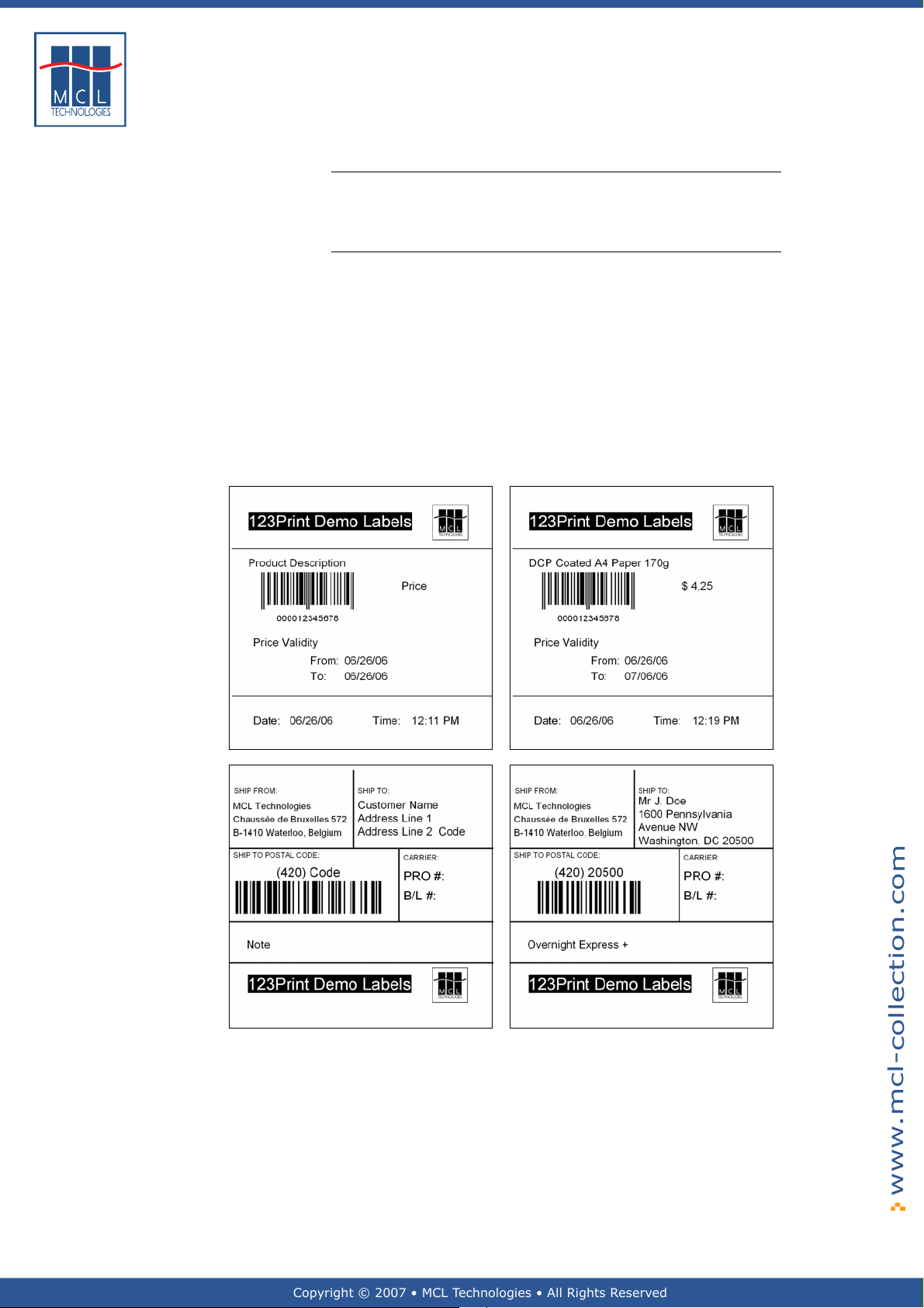
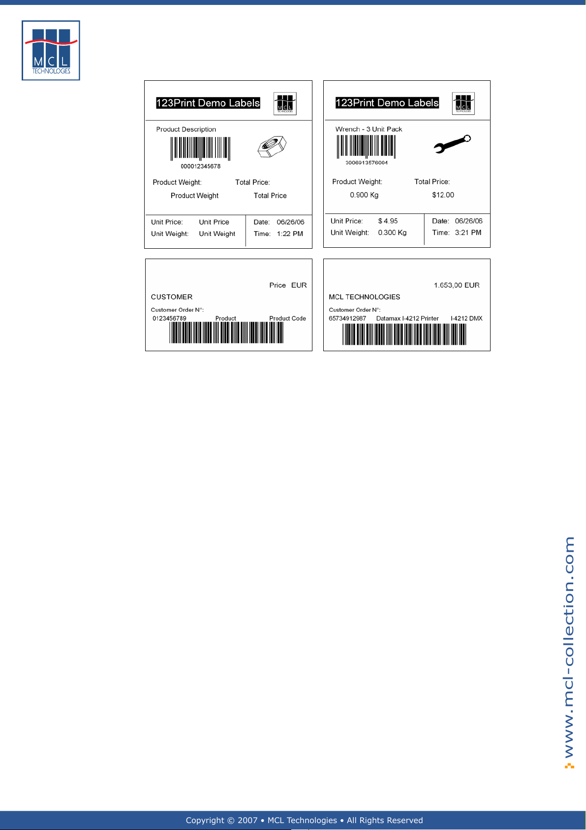
General introduction This section shows some sample labels to give you an idea of the
Sample labels The sample labels shown here were designed using Seagull’ s
kinds of labels you can print using 123 Print projects on Datamax
printers.
BarTender label creation software.
123 Print provides the capability to associate and print variable data
on labels.
Consider the sample labels shown below. The labels on the left are
templates that would be saved on your printer with your 123 Print
project. The labels on the right show the actua l label that will come
off the printer after the 123 Print project inserts the variable data
into the template and initiate s a print of the completed label.
Your 123 Print project can receive variable data from many
sources—barcode scanner input, weight scale input, user keyboard
input, lookup files, etc.
October 2007 Page
Page 8
Copyright © 2007 • MCL Technologies • All Rights Reserved
www.mcl-collection.com
8
Chapter 1 : Primer
October 2007 Page
Page 9
Copyright © 2007 • MCL Technologies • All Rights Reserved
www.mcl-collection.com
9
Chapter 1 : Primer
1.3. Project Flow
General introduction 123 Print structures your project flow using a combination of screens
User Interface Every 123 Print project follows a pre-defined screen flow. You configure
and processes that you create via 123 Print’s User Interface and
Labels.
This section gives a high level view of the flow and interrelation ship
between the screens that are created via the User I nterface and those
created via Labels.
With User Interface, you can print any static label you want.
With Labels, you can change a static label into a dynamic label by
merging in variable data from data collection, user screen prompts, and
processing logic.
Please reference Section
for detailed information about these functions.
these screens through the User Interface function. This is the only
screen flow function you need if you want to print static labels.
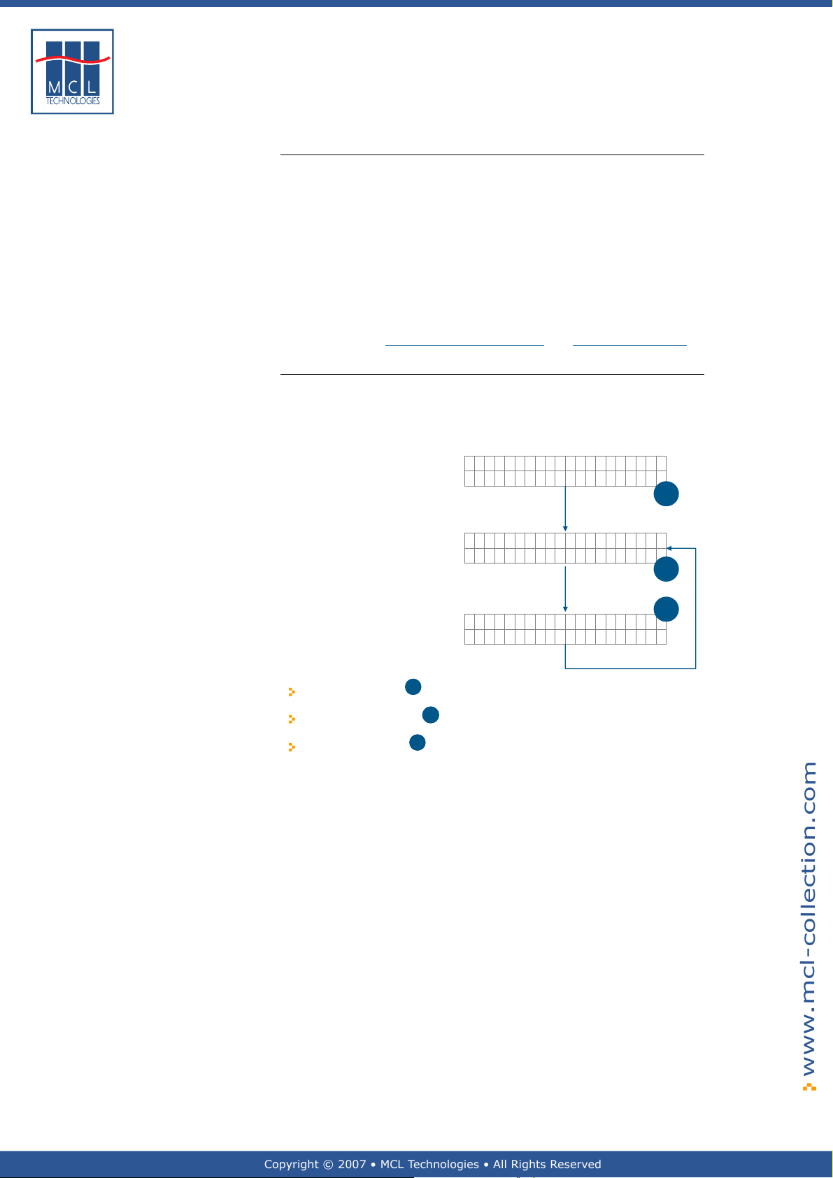
This core flow is depicted here.
3.2 – User Interface and Section 3.3 – Labels
Your Project Name
Ver 1.00
1
Select Label:
<Label Name>
2
3
<Label name>
Qty to Print:
The first screen 1 is a Welcome screen.
The second screen is the Select Label screen.
The third screen 3 is the Quantity to Print screen.
These screens are displayed in a black font on the Datamax printers.
When your 123 Print project is run on the printer, it first displays the
Welcome screen. It then goes into a lo o p alternating display between
the Select Label screen and the Quantity to Print screen.
Your application will loop infinitely between the second and third
screens until you press the Menu (ESC) button on the front panel of the
Datamax printer.
As you design your project in 123 Print, you have the option to
customize the Welcome screen. By default 123 Print proposes your
project name for the Welcome screen.
You then add the labels you want to be able to print from your project.
When your project is run, this list of labels is presented on screen (2).
The user presses the Fwd ↑ and Rev ↓ buttons on the printer’s front
panel to scroll through the list of available labels and, by pressing the
Ent ↵ button, selects the label that is required for a given operation.
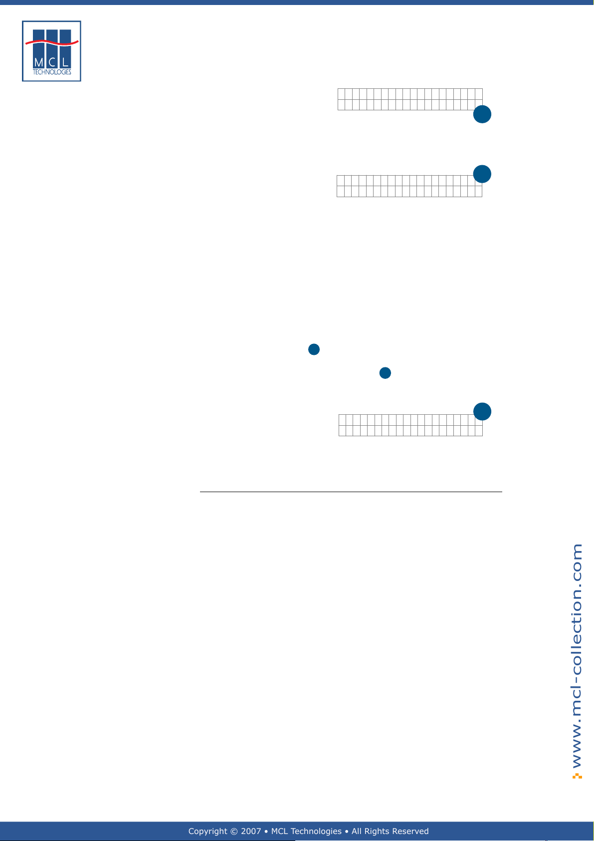
Here is an example of what screen (2) might look like on a printer when
the fourth label in your project is a label f or pallets:
October 2007 Page
Page 10
Copyright © 2007 • MCL Technologies • All Rights Reserved
www.mcl-collection.com
10
Chapter 1 : Primer
Select Label:004
▼▲
Pallet Label
2
In this case, the third screen will look like the scr een below. Notice that
the label name, Pallet Label, from screen (2) has au tomatically been
displayed on the first line of screen (3).
Pallet Label
Qty to Print:1..
The user presses the Fwd ↑ and Rev ↓ buttons on the printer’s front
panel to increment or decrement the quantity of the label to be printed.
The user then presses the Ent ↵ button on the printer’s front panel to
initiate the printing. The label is printed in the quantity specified. The
project then loops back to display screen (2) again. The user can select
the same label for printing again, or may select a different label to
print.
This is useful in pallet building, for example. You may want to print
many item labels. Then, when all the items on the pallet have been
labeled, you can print a label for the e ntire pallet. In this case, the user
selects the item label many times and then finally selects the pallet
label once. The user then returns to printing item labels for the next
pallet build.
A fourth standard screen
of the 123 Print application logic but rather is displayed by the Datamax
printer whenever a print error occurs after
The default print error screen is as shown here
4
, a Print Error screen, exists. It is not part
3
above has been initiated.
3
▼▲
Print Error
4
Exit Retry
This message will be displayed, for example, if the label roll is out of
labels.
The User Interface function allows you to customize this error message.
Labels If you are only concerned with static labels, you only need to use the
Labels function to identify the static labels you want to include in your
project.
If, however, you want to create dynamic labels, you will want to take
advantage of the full capabilities provided in the Labels function.
The flow described above under User Interface is not sufficient to
include variable data on the label. Consider an item label, for example.
You want to print an item label with an item barcode, an item
description, and an item weight. However, you do not know in advance
which item, the item description, or the item weight (fruit, meat, etc.)
for the label to be printed. You want to collect this information and
merge it with your label format at the moment you print the label.
123 Print allows you to design this capability into your project. It allows
you to create a series of screens for user interaction, and implement a
series of processes for data manipulation or peripheral communications.
Since each label may involve a different set of variable data, these
screens and processes are associated with the given label in what is
called a label program.
Using the Labels function, you can design a series of screens and
processes to collect data that you then merge as variables into the label
to be printed.
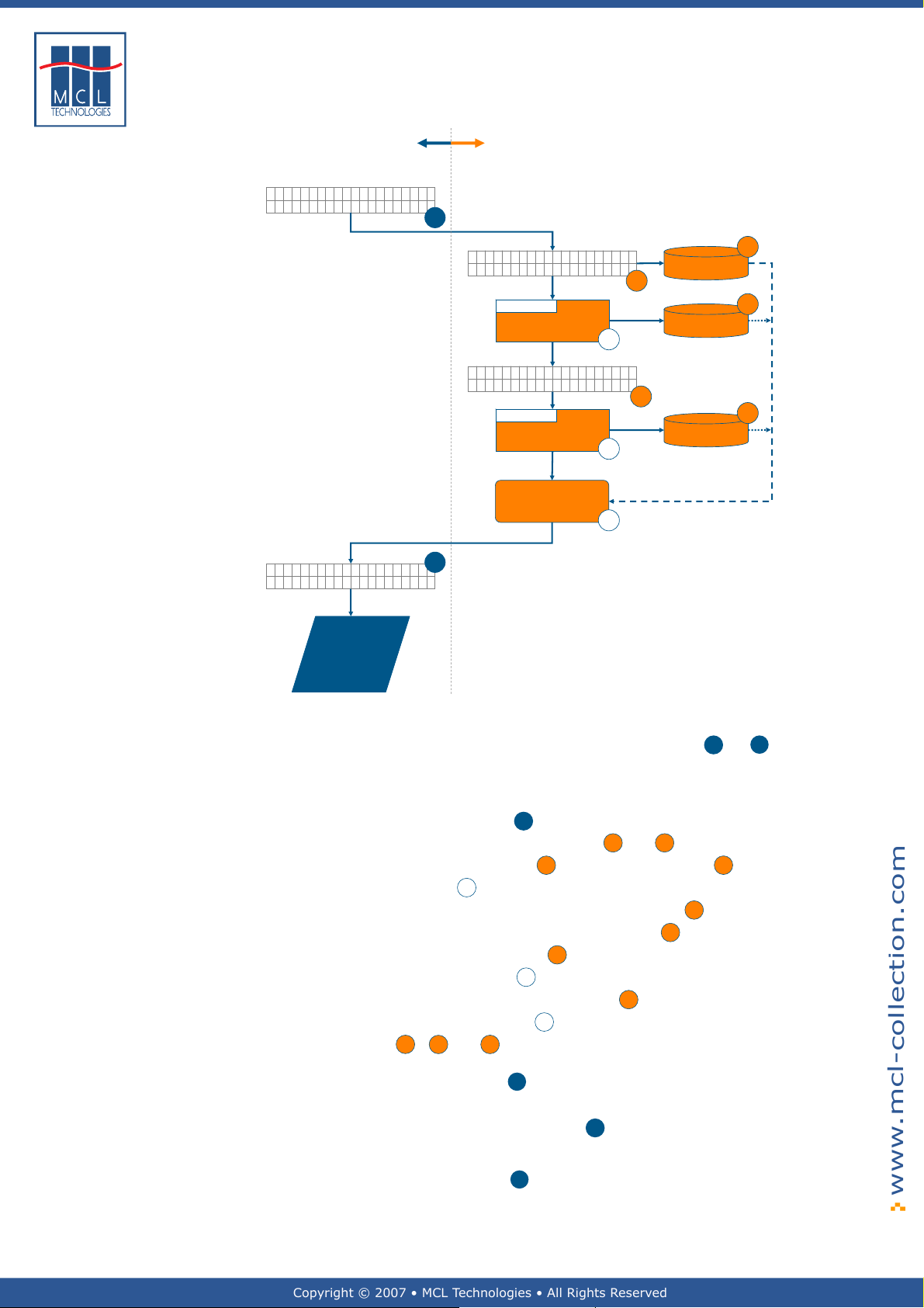
The following diagram depicts the relationship between User Interfa ce
created screens and flow, and Labels created screens and flow.
October 2007 Page
Page 11
Copyright © 2007 • MCL Technologies • All Rights Reserved
www.mcl-collection.com
11
Chapter 1 : Primer
User Interface:
Core screen flow
Select Label:003
Item Label
Item Label
Qty to Print:1..
▼▲
▼▲
Labels:
Label program
2
Enter Item Code
_____________
Process:
Get Item Descripti on
from Lookup File
Item on Scale? Y/N
_
Process:
Weigh Item
Map variables into
label format
3
C
Item Code
A
D
Item
X
Description
B
E
Item’s Weight
Y
Z
Label printed
with item
code, item
description
and weight
merged in
User Interface:
The left-hand side of the diagram shows the core flow created
by User Interface. User input is required on screens
Labels:
The right-hand side of the diagram shows the flow of a label
program to capture the variable data needed to complete the
item label selected at
User input is required on screens at
The item code entered in
A process at
X
is used to browse through a lookup file to get
the item description for the item code entered in
The item description is saved in a variable at
When the user indicates at
weighed, a process at
save the item’s weight in a variable at
Label Mapping is used at
C
in
, D and E with the label format for the item label
The variable label information is then passed back to the User
Interface function at
User Interface and Labels relationship:
The selection of the item label at
program depicted on the right-hand side of the diagram
When the label program is finished, it passes control back to
the User Interface at
A
and B
A
is saved in a variable at C
A
D
B
that the item is ready to be
Y
is used to read the weight scale and
E
Z
to merge the variable data saved
3
for printing
starts the related label
3
to print the label
and 3
October 2007 Page
Page 12

Copyright © 2007 • MCL Technologies • All Rights Reserved
www.mcl-collection.com
2. Getting Started
Overview
Chapter 2
introduction
Topics This chapter covers the following topics:
This chapter describes the installation and setup of 123 Print.
Topic Page
Chapter 2 : Getting Started
2.1.
2.2
2.3
Installation
Activation
General Setup
2.3.1 DPL Connection
2.3.2 MCL Connection
2.3.3 Local Settings
2.3.4 Others
13
17
25
October 2007 Page 12
Page 13
Copyright © 2007 • MCL Technologies • All Rights Reserved
www.mcl-collection.com
13
2.1. Installation
General introduction This section describes how to install 123 Print.
Chapter 2 : Getting Started
Installation
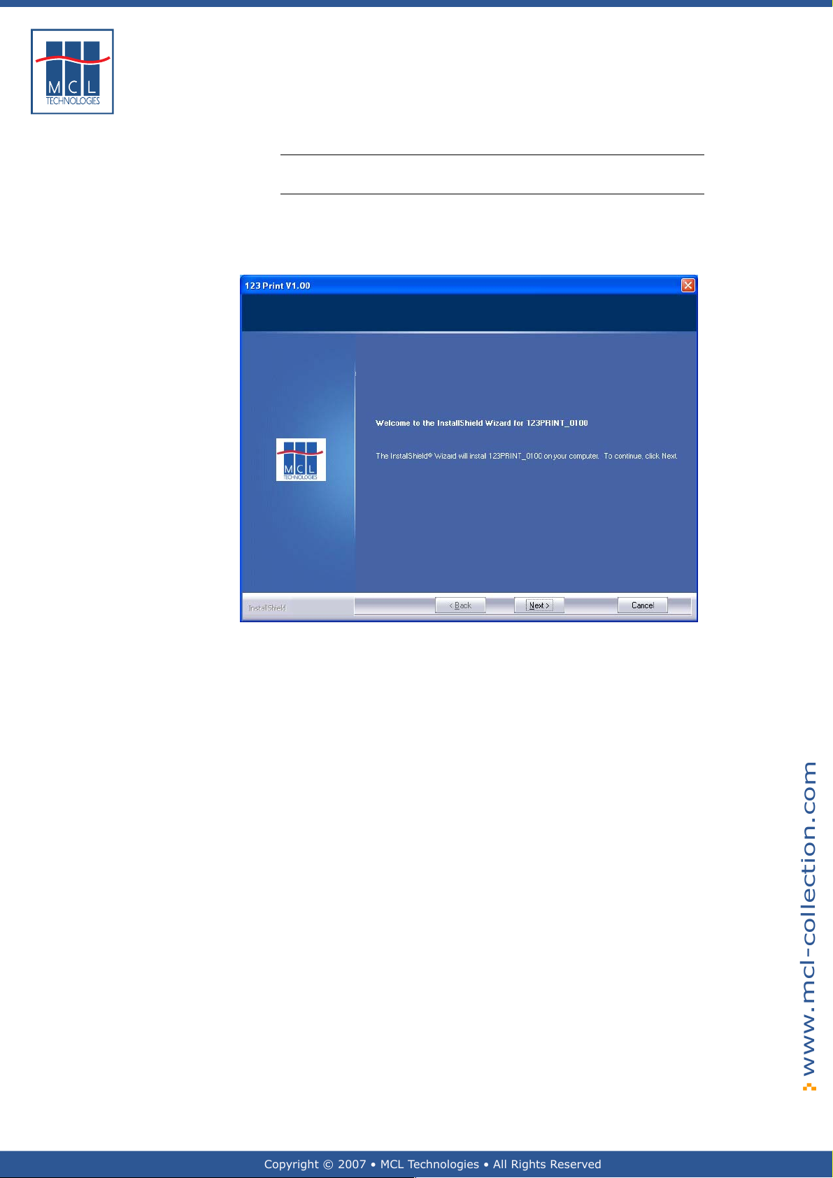
1 Double-click on the 123 Print installation executable which you
have downloaded. The default folder in which 123 Print is installed
is C:\123Print
A welcome screen is displayed as shown below
2 Click Next to proceed with the installation
October 2007 Page
Page 14
Copyright © 2007 • MCL Technologies • All Rights Reserved
www.mcl-collection.com
14
Chapter 2 : Getting Started
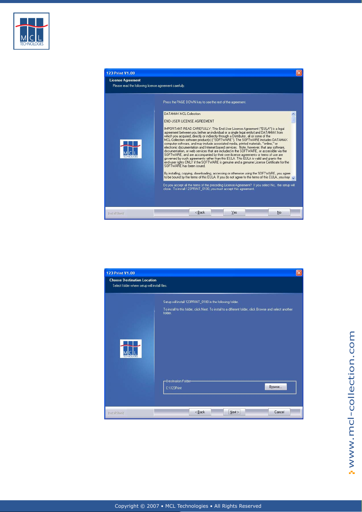
An end-user license agreement is displayed as shown below
To accept the license terms and proceed
3 Click Yes
As shown below, a screen is displayed prompting you to enter the
location where you want to install 123 Print.
4 Click Next to use the default folder for your installation, or
5 Edit the entry or browse for the folder where you want to install
123 Print
6 Click Next
October 2007 Page
Page 15
Copyright © 2007 • MCL Technologies • All Rights Reserved
www.mcl-collection.com
15
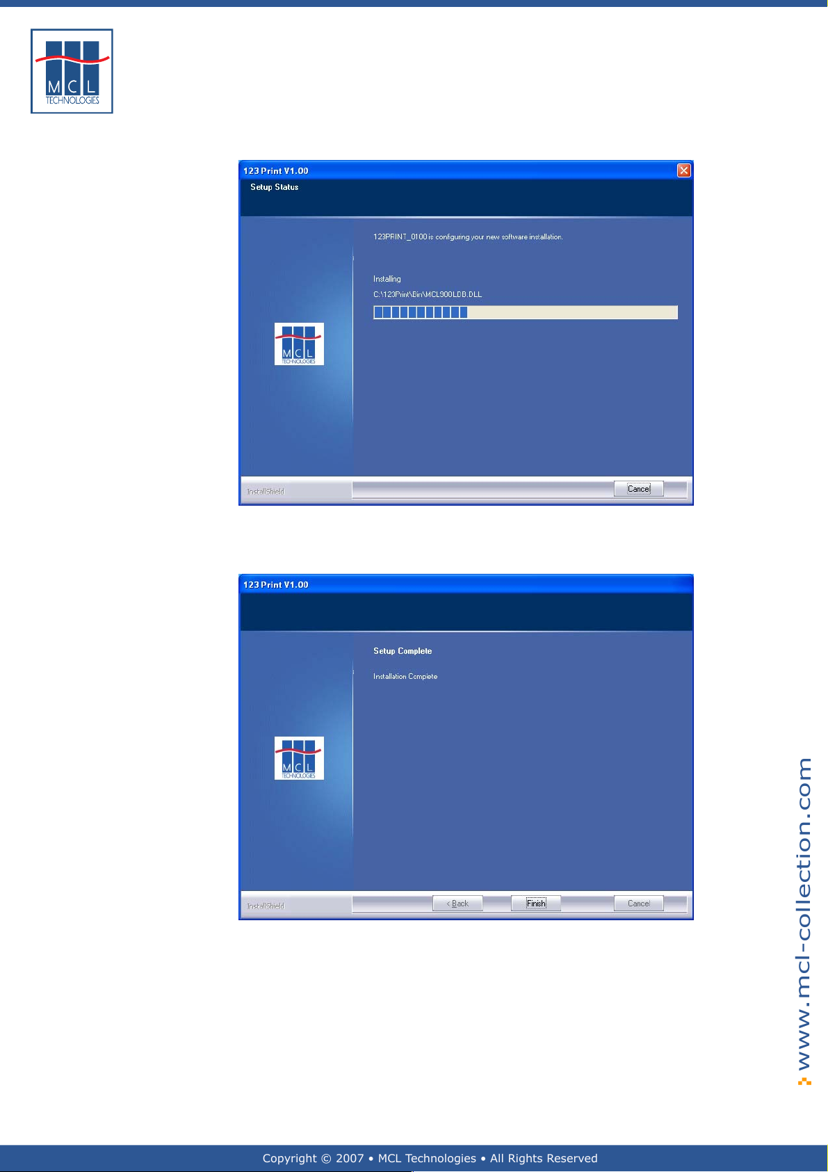
As shown below, a screen is displayed to show you the progress of the
installation
Chapter 2 : Getting Started
The following is displayed when installation is completed
7 Click Finish
October 2007 Page
Page 16
Copyright © 2007 • MCL Technologies • All Rights Reserved
www.mcl-collection.com
16
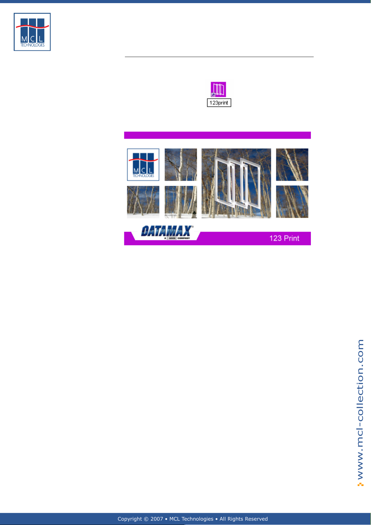
Starting 123 Print Once 123 Print is installed, start it by:
1 Double click on the 123 Print shortcut icon on the Windows
desktop
Chapter 2 : Getting Started
The 123 Print splash screen is superimposed on the 123 Print
environment
October 2007 Page
Page 17
Copyright © 2007 • MCL Technologies • All Rights Reserved
www.mcl-collection.com
17
Chapter 2 : Getting Started
2.2. Activation
General introduction This section describes the activation process for 123 Print.
During the activation process you will be prompted to choose between a
Software Activation and a Hardware Activation for your 123 Print
license. Be sure to understand the benefits of each method and the
consequences of choosing one method over the other.
Be sure to make your choice carefully. The activation method you
choose cannot be changed at a later stage.
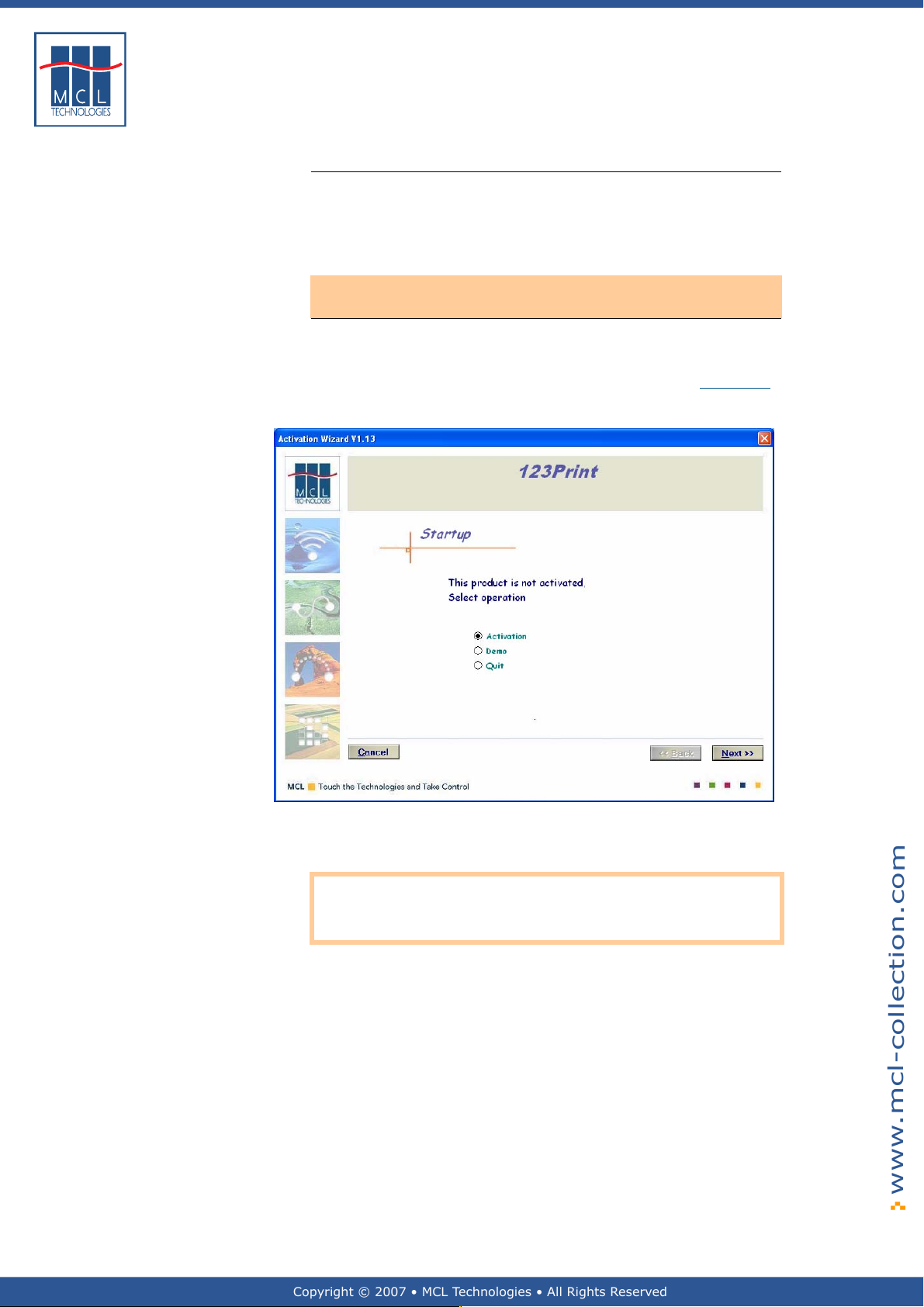
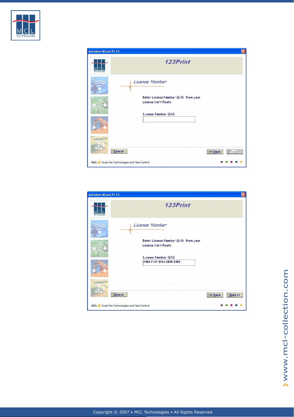
Activation The first time you run 123 Print, you will be prompted to Activate the
software. To do this, you will need to have the License Certif icate ready
which you have received, by email, when you ordered 123 Print.
1 Get out your 123 Print License Certificate. Please see Appendix A
for a sample certificate.
2 Click Next to begin the Activation Process.
Note: No activation is requir ed to run the software in demo mode.
However, 123 Print has reduced capabilities when it is run in demo
mode. For example, you cannot download a project or execute a script.
October 2007 Page
Page 18
Copyright © 2007 • MCL Technologies • All Rights Reserved
www.mcl-collection.com
18
Chapter 2 : Getting Started
3 Enter the License Number found on your License Certificate
4 Click Next
October 2007 Page
Page 19
Copyright © 2007 • MCL Technologies • All Rights Reserved
www.mcl-collection.com
19
End-user license
agreement
Chapter 2 : Getting Started
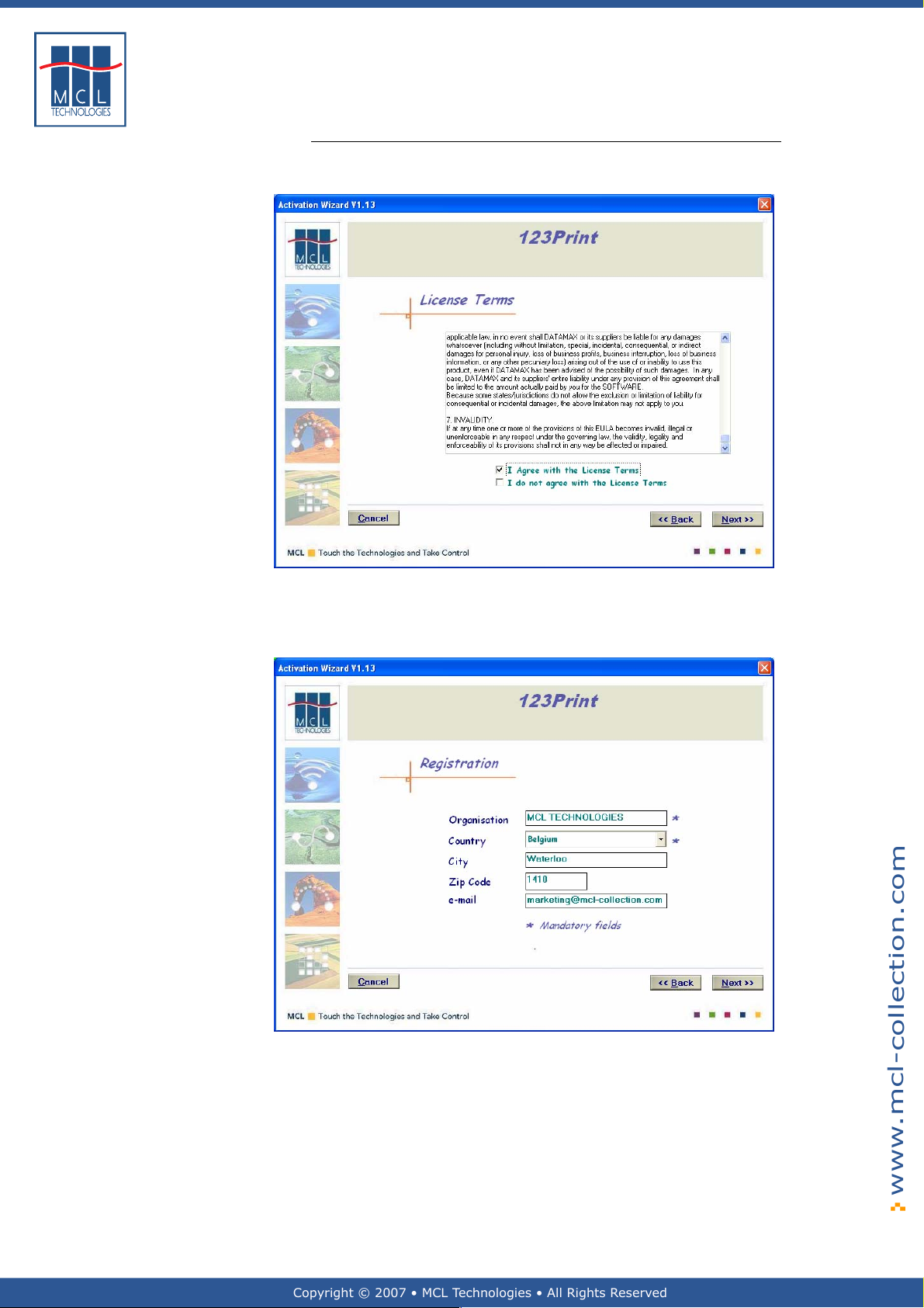
MCL’s End-User License Agreement is displayed as shown below. Before
proceeding, you must read and accept these license terms.
5 Read and scroll down to the bottom of the terms
6 Check the checkbox to accept the license terms
7 Click Next
The 123 Print software registration form is displayed
8 Enter the details of the company to whom the License should be
registered
9 Click Next
Note: Only Organisation and Country are compulsory fields. However,
the more details you provide, the easier it will be for MCL Technologies
to provide technical assistance in the future, should assistance be
necessary.
October 2007 Page
Page 20
Copyright © 2007 • MCL Technologies • All Rights Reserved
www.mcl-collection.com
20
Software versus
hardware activation
Chapter 2 : Getting Started
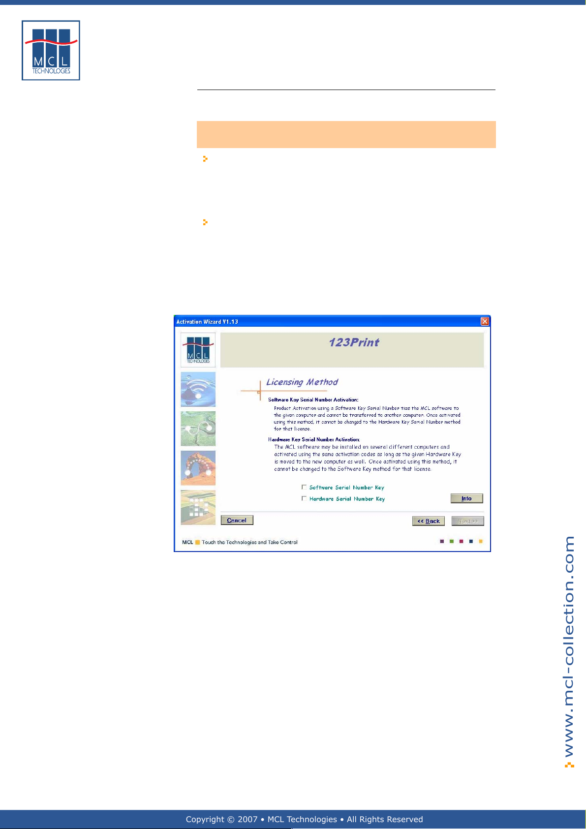
The next step is to choose between Software Activation and Hardware
Activation.
This choice is very important as it cannot be changed at a later
stage.
Software Activation: Using this method of activation, 123 Print
computes a Serial Number from various components on your PC.
123 Print then ties your license number to this computed Serial
Number. Thus, your software becomes PC Dependent. You will
not be able to transfer your licensing details over to a different PC
if you want to install and run 123 Print on a different PC.
Hardware Activation: This method of activation requires the
purchase of a Hardware Serial Number Key. Using this method of
activation, 123 Print ties your license number to the serial number
of your Hardware Key. Thus your software becomes PC
Independent. This means you can install and run 123 Print on a
different PC at anytime, providing you are able to plug your
Hardware Serial Number Key into the other PC. The Hardware Key
must be present for the software to run.
Once you have made your choice between Software and Hardware
activation:
10 Check the appropriate checkbox
11 Click Next
October 2007 Page
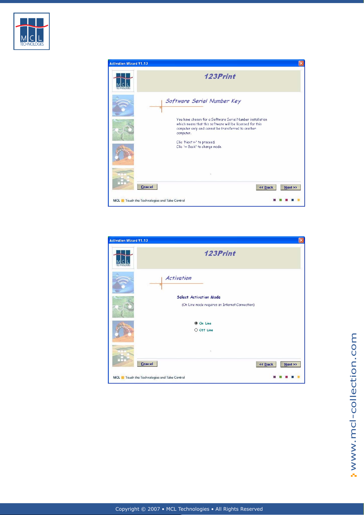
You are prompted to confirm your selection as shown below
Page 21
Copyright © 2007 • MCL Technologies • All Rights Reserved
www.mcl-collection.com
21
Chapter 2 : Getting Started
12 Click Next to confirm and proceed
The Activation mode screen is displayed as shown here
Indicate if you want to use on-line or off-line activation
13 Click the appropriate radio button
14 Click Next
Your system needs internet access for on-line activation to be possib le.
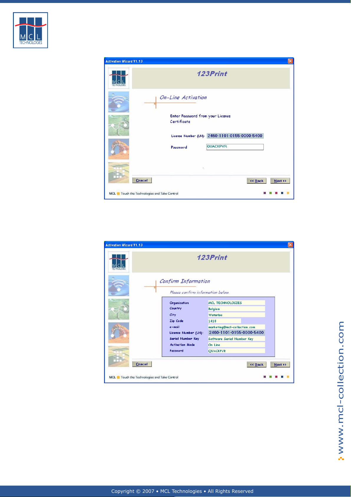
This example uses on-line activation. Consequen tly, the On-Line
Activation screen is displayed as shown below.
The off-line activation mode will step you through the activation process
in a similar fashion.
October 2007 Page
Page 22
Copyright © 2007 • MCL Technologies • All Rights Reserved
www.mcl-collection.com
22
Chapter 2 : Getting Started
15 Enter the Password found on your License Certificate
16 Click Next
You are prompted to confirm that your registration information is
accurate
17 Click Next to confirm the details you entered on the previous
October 2007 Page
screens.
123 Print now connects to MCL’s Licensing Server and records your
details on the server. The Licensing Server then returns an Activation
Key. When the Activation Key is received, your software is ready to be
used.
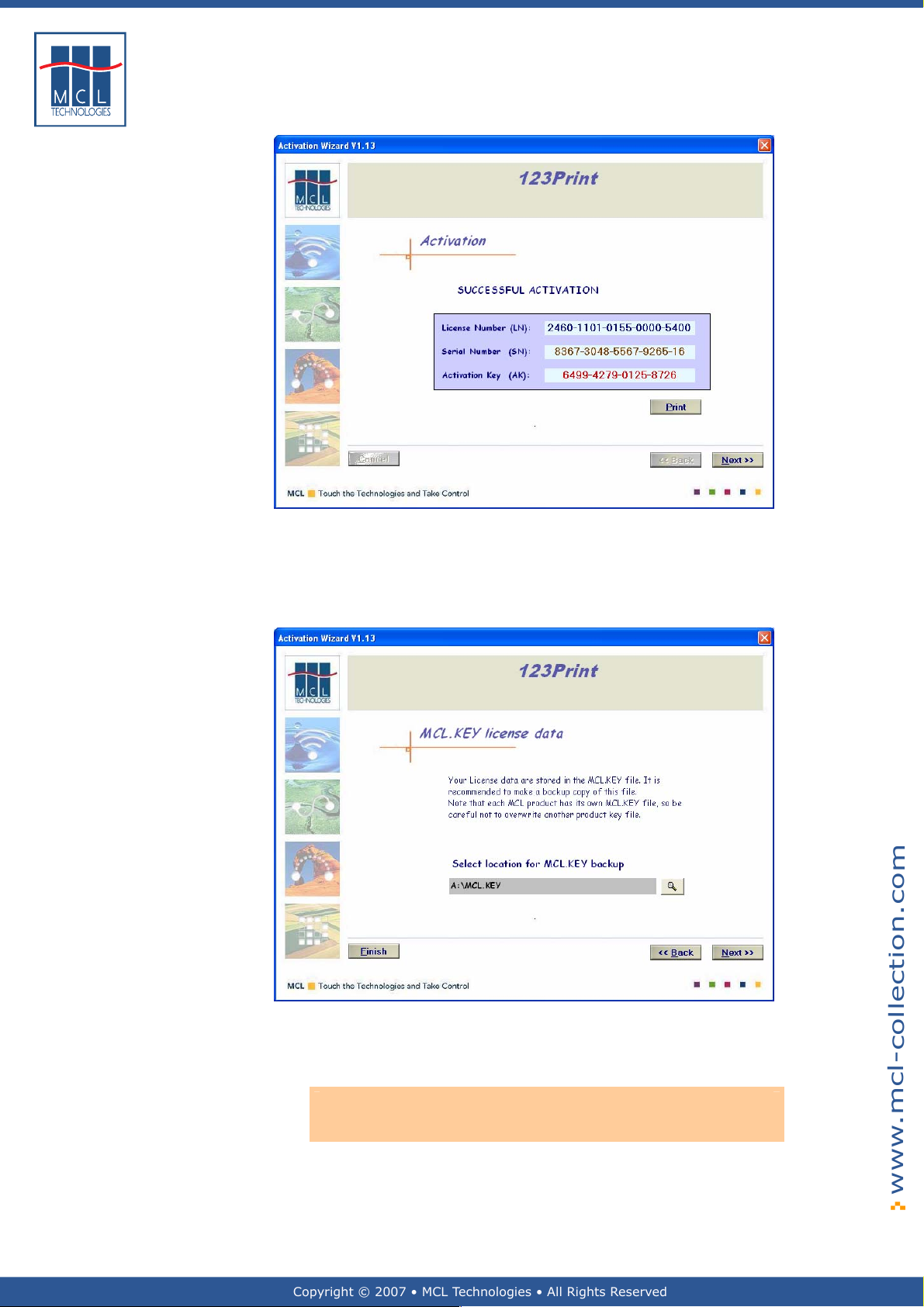
An Activation successful screen is displayed as shown below.
Page 23
Copyright © 2007 • MCL Technologies • All Rights Reserved
www.mcl-collection.com
23
18 Print this information and keep it in a safe place for later use in
case of disaster recovery.
Chapter 2 : Getting Started
19 Click Next to validate your activation.
You are now prompted to save a backup of your License Key. It includes
your license number, serial number and activation key.
20 Edit the entry or browse to the location where you want your
License Key backed up
21 Click Next
Note: It is very important for you to record and save a backup of your
license key. This is the only way MCL Technologies can help you recover
your 123 Print license in the event of a disaster.
October 2007 Page
Page 24
Copyright © 2007 • MCL Technologies • All Rights Reserved
www.mcl-collection.com
24
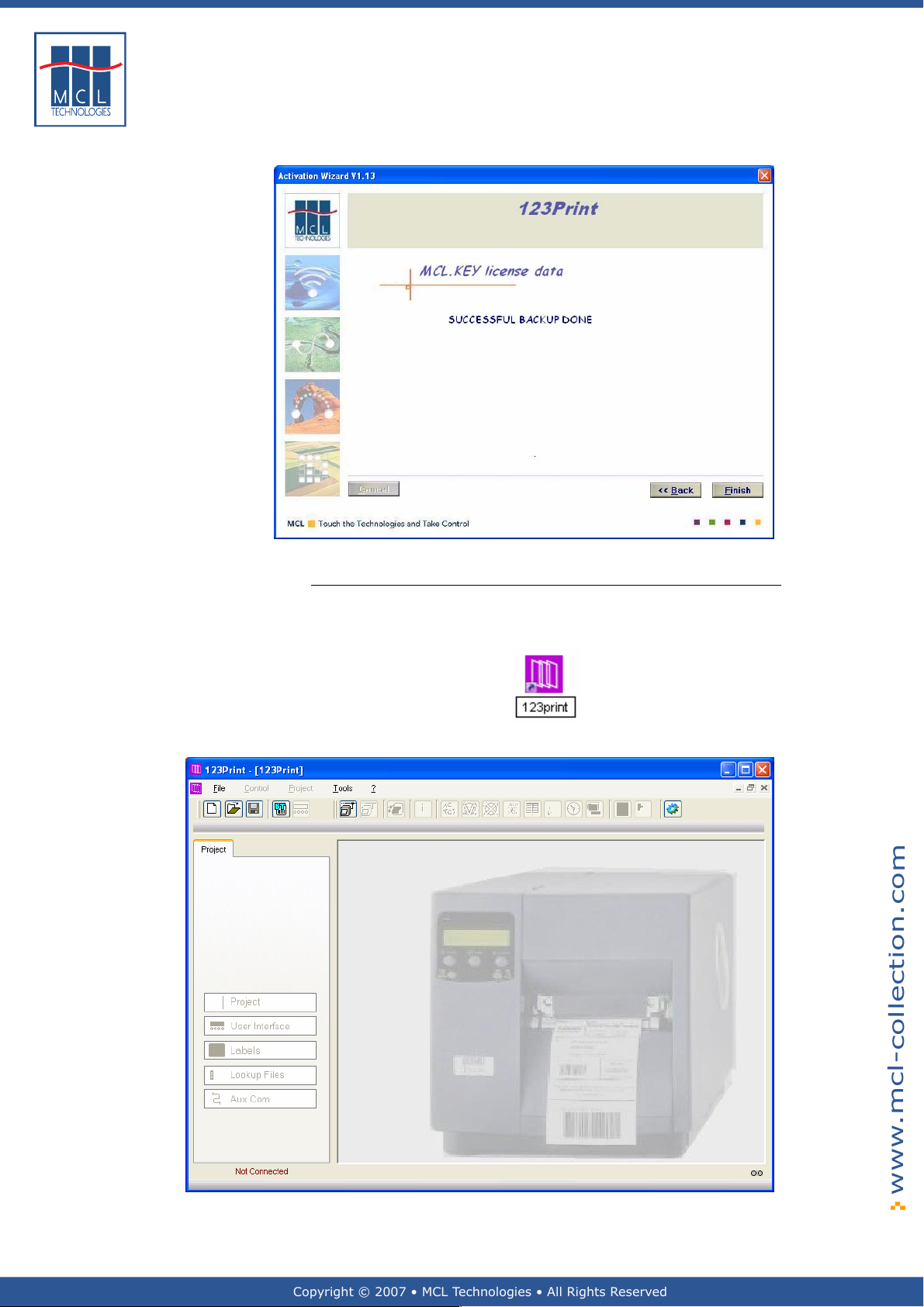
A successful backup screen is displayed as shown here.
Chapter 2 : Getting Started
Starting 123 Print When the activation is completed, 123 Print is started automatically. To
22 Click Finish
start 123 Print again in the future, double click on the 123 Print short
cut on the Windows desktop
The main 123 Print window is displayed as shown here
October 2007 Page
Page 25
Copyright © 2007 • MCL Technologies • All Rights Reserved
www.mcl-collection.com
25
Chapter 2 : Getting Started
2.3. General Setup
General introduction This section describes the setup of 123 Print to allow it to operate in
Setup To enter 123 Print’s setup, on the menu bar:
your environment. This setup involves the settings that are required by
123 Print to work with your printer, simulate your project, and integrate
with BarTender.
1 Click Tools
2 Click 123 Print Settings
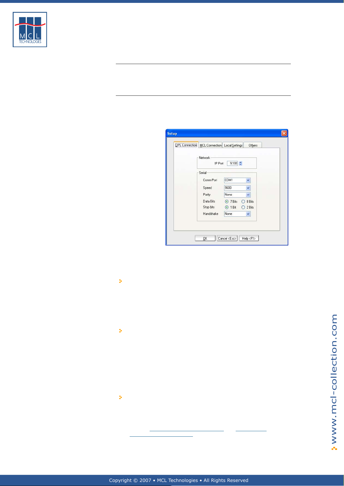
The Setup dialogue box is displayed as shown here
Before you can do anything using 123 Print, you need to set up 123
Print for initial communicat ions with your printer for DPL Mode and MCL
Mode where:
DPL Mode refers to the mode in which 123 Print communicates with
the printer using DPL commands.
DPL is the Datamax language used to print a label and control the
printer. These are commands like <STX>F. Please refer to your
Datamax manual for more information.
DPL Mode is a one-way communication between 123 Print and the
printer.
MCL Mode refers to the mode in which 123 Print communicates
with the printer using MCL commands to direct the printer and run
MCL applications.
These are commands like NO|001|TF|INVENTORY.DAT|AA.DAT.
Please refer to your MCL-Link manual for more information.
MCL Mode is a two-way communication between 123 Print and the
printer. For example, 123 Print may ask for a parameter and
receive values in return, or 123 Print may send a file and receive
an acknowledgement upon the successful completion of the
transmission.
123 Print determines which mode to use—DPL Mode or MCL Mode.
123 Print always tries to use MCL Mode as the default mode.
However, if it cannot establish communications using MCL Mode,
then 123 Print reverts to using DPL Mode. This will occur if the
printer settings and 123 Print settings do not match for the values
given in Section
Connect/Disconnect Printer
2.3.2 – MCL Connection and Section 7.1 –
.
October 2007 Page
Page 26
Copyright © 2007 • MCL Technologies • All Rights Reserved
www.mcl-collection.com
26
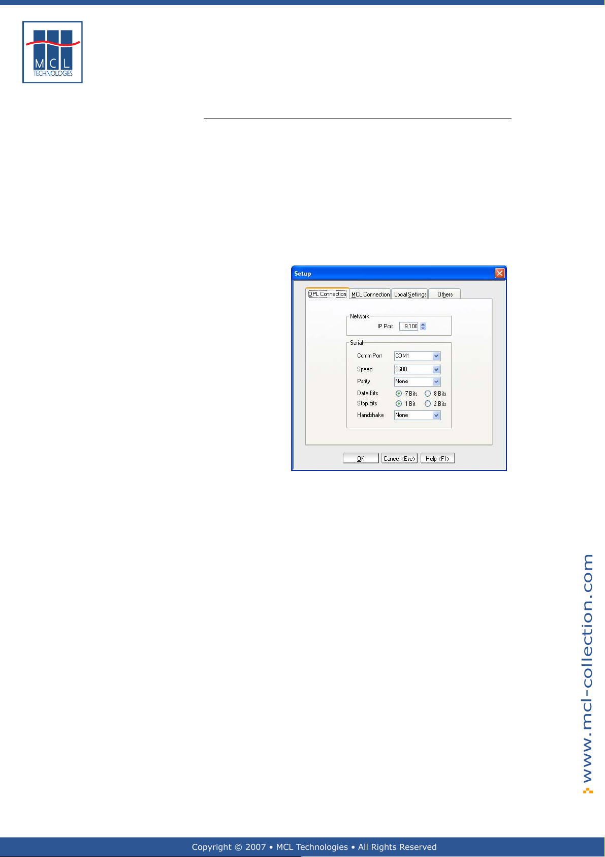
2.3.1. DPL Connection
DPL Connection Setup your printer interface fo r DPL Mode communications. In the
Setup dialogue box:
1 Click on the DPL Connection tab
If you want to use network communications for your DPL commands :
2 Edit the Printer TCP port with the appropriate port number
(typically 9100 or 3000).
If you want to use serial communications for your DPL commands:
3 Edit the Serial settings with values appropriate for your printer
These values may be found through the menu on your printer or in
your Datamax printer manual.
Chapter 2 : Getting Started
October 2007 Page
Page 27
Copyright © 2007 • MCL Technologies • All Rights Reserved
www.mcl-collection.com
27
Chapter 2 : Getting Started
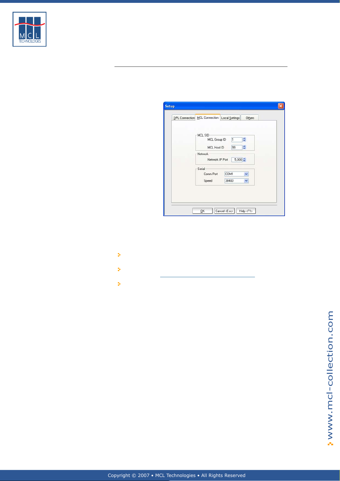
2.3.2. MCL Connection
MCL Connection Next setup yo ur printer interface for MCL Mode communications. In the
Setup dialogue box:
1 Click on the MCL Connection tab
The MCL Connection options screen is displayed as shown here
MCL Group ID can be any number from 001 to 255.
In the MCL Group ID setting, enter the value of the Group ID you
assigned to the printer to which you want to connect.
Think of the Group ID as a way of segmenting your printers similar
to a subnet segmentation of network devices.
Each printer is identified by 123 Print by combining Group ID +
MCL ID. (See Section
If you have, for example, 750 printers on your network, segment
your printers into 3 groups of 250 printers each. Assign each of the
250 printers to the same group and assign a Group ID of 001, 002
or 003, for example, to those printers. Then assign a unique MCL
ID such as a number from 001 – 250 to each of the printers within
the group.
These assignments will allow you to uniquely identify all 750
printers on your network.
MCL Host ID can be any number from 001 to 255. It is typically set to
099. This ID is used by the MCL protocol for communications between
the Datamax Printers and 123 Print. The MCL Host ID is used to identify
123 Print as the host for these printer communications.
UDP Port is typically 5000.
Comm Port is the port that 123 Print should use on its own platform to
communicate serially with a printer.
Speed is the baud rate of the serial port as determined by the printer.
Please reference your Datamax manual for information about serial
comm speed.
7.1 – Connect/Disconnect Printer).
October 2007 Page
Page 28
Copyright © 2007 • MCL Technologies • All Rights Reserved
www.mcl-collection.com
28
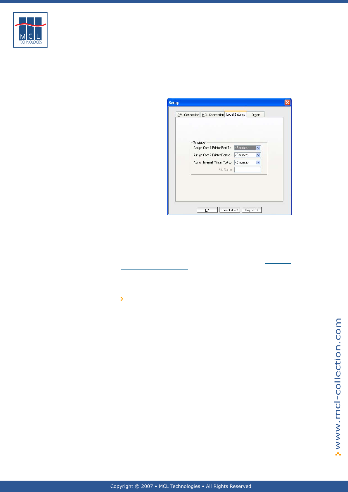
2.3.3. Local Settings
Local Settings Next, setup project simulation options. In the Setup dialogue box:
1 Click on the Local Settings tab
The Local Settings screen is displayed as shown here
Chapter 2 : Getting Started
The project you run on a printer may require inputs from peripherals
such as a barcode scanner on printer port 1 and weight scale on printer
port 2.
Therefore, when you simulate your project in 123 Print, you will want to
emulate the input these peripherals give or connect directly to the given
peripheral to receive its input on your development PC. (See Chapter 6
– Simulating Your Project).
This Simulation setup lets you define the source—emulation or
peripheral connection to a port on your PC—of these inputs for your
simulation.
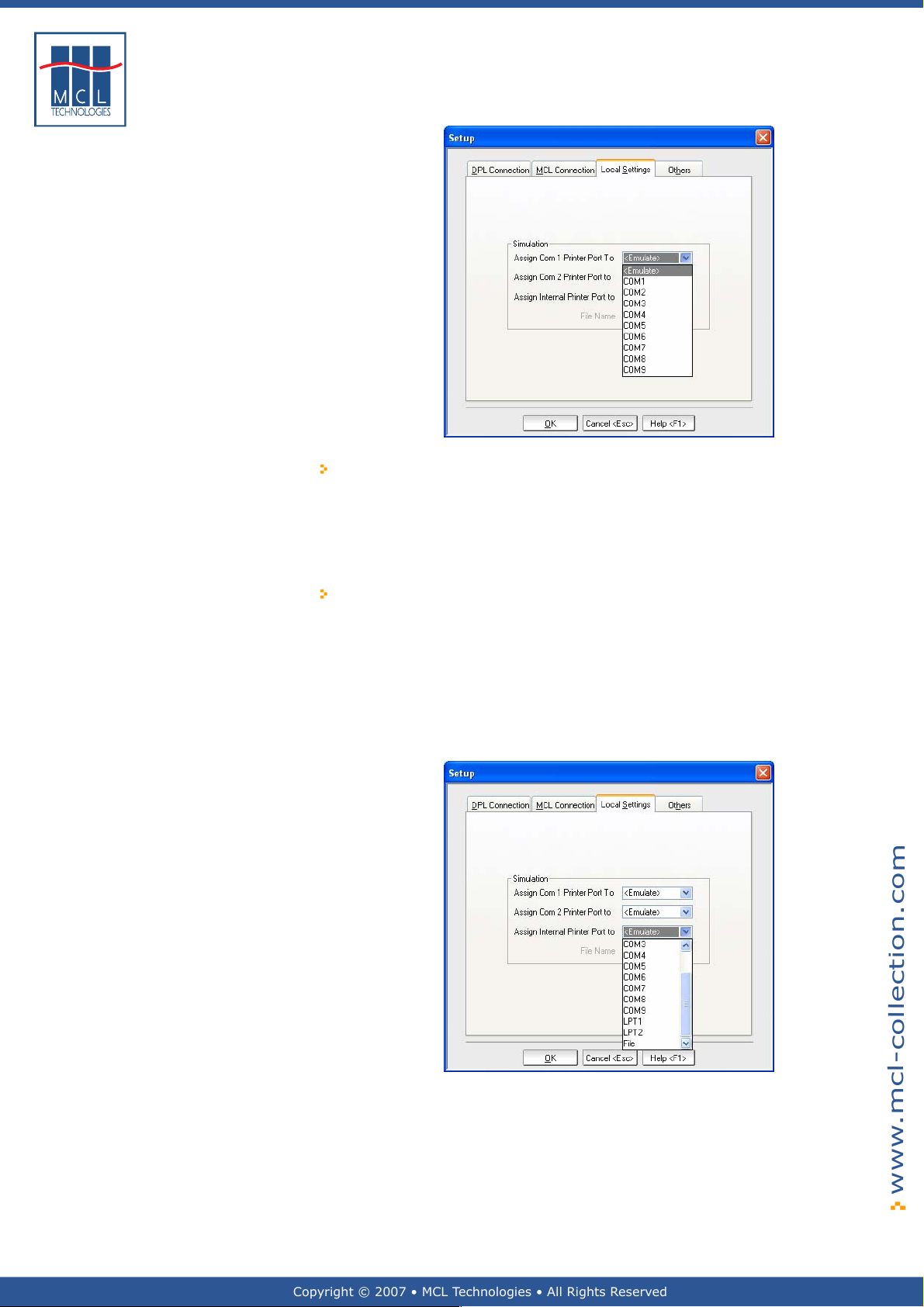
Assign Com 1 Printer Port To
This option lets you indicate from where the simulator should
fetch the port 1 input in simulation. This is to simulate what
the final project will receive from printer port 1 when th e
project is running on a printer.
If this is a barcode scanner, you can choose to emulate the
scanner input, or you can connect the scanner to any port on
your PC. Indicate the port to which the barcode scanner will
actually be connected on your PC. The 123 Print simulator will
map this port as port 1 input.
2 Select the desired option for printer port 1 simulation.
The com 1 simulation setting options are as shown below
October 2007 Page
Page 29
Copyright © 2007 • MCL Technologies • All Rights Reserved
www.mcl-collection.com
29
Assign Com 2 Printer Port To
This option is identical to the Assign Com 1 option. This option
simply lets you simulate a peripheral, such as a weight scale,
that would normally be connected to port 2 on the printer.
Chapter 2 : Getting Started
3 Select the desired option for printer port 2 simulation
Assign Internal Printer Port To
This option allows you to simulate label printing when you are
running your project in simulation.
You can emulate the label print or send the label as output to a
port on your development PC.
The output may be sent to a serial com port, an LPT (parallel)
port, or to a file. Sending the output to a file is useful if you
want to see the DPL code your project is using to print labels
The internal printer port simulation options are as shown below
on your printer.
4 Select the desired option for label printing simulation
5 Click OK
October 2007 Page
Page 30
Copyright © 2007 • MCL Technologies • All Rights Reserved
www.mcl-collection.com
30
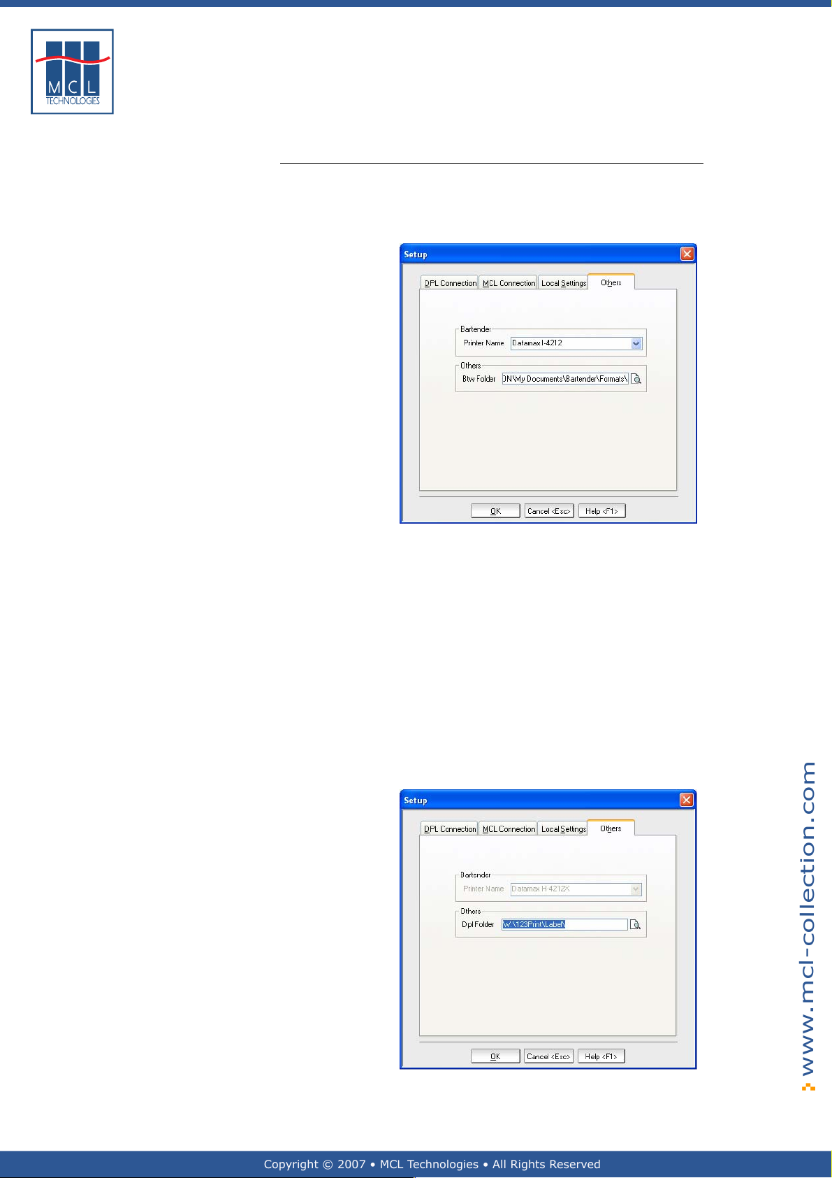
2.3.4. Others
Others Set up the values for 123 Print’s integration with BarTender or DPL
labels. In the Setup window:
1 Click the Others tab
The Others dialogue box is displayed as shown here
Chapter 2 : Getting Started
If BarTender is installed and activated on your system:
2 In the Printer Name field, identify the default printer to be used for
your project. 123 Print passes this printer model to BarTender to
use as the default printer for label design for your project when you
invoke BarTender from the 123 Print toolbar while creating your
project.
3 In the BTW Folder field, navigate to the folder you plan to use as
your common folder for your BarTender labels.
By default if BarTender is installed on your system, 123 Print assigns
MyDocuments/BarTender/Formats for your BarTender labels. This is the
default path BarTender uses when saving labels.
If BarTender is not installed on your system, 123 Print expects your
labels to be DPL labels. It assigns a default path of C:\123Print\Label as
the location of your DPL label folder.
4 Click OK to use this path or navigate to the folder you want to use
October 2007 Page
Page 31

Copyright © 2007 • MCL Technologies • All Rights Reserved
www.mcl-collection.com
Timer is used to set the duration, in seconds, of the display of the
Welcome screen. The Welcome screen is typically displayed
momentarily only
Chapter 2 : Getting Started
5 Edit the timer value, or
6 Use the up and down arrows beside the timer field to increment
or decrement the value of the field.
October 2007 Page
31
Page 32

Copyright © 2007 • MCL Technologies • All Rights Reserved
www.mcl-collection.com
3. Creating a Project
Overview
Chapter 3
introduction
Description 123 Print provides you with all the tools necessary to create
Topics This chapter covers the following topics:
This chapter describes how to use 123 Print to create projects and label
programs for your Datamax printers.
applications for your Datamax printer. A 123 Print project involves 4
basic screens:
Welcome Screen
Select Label screen
Quantity to Print screen
Print Error Message screen
You may associate several additional screens (up to 50) with each label
in your project. As you create these additional screens you are creating
what is called a label program.
Chapter 3 : Creating a Project
Topic Page
33
35
51
89
110
Display Only
3.1.
3.2
3.3
3.4
3.5
Project Description
User Interface
Labels
Lookup Files
System Setup
3.2.1 Welcome Screen
3.2.2 Select Label Screen
3.2.3 Quantity to Print Screen
3.2.4 Print Error Message Screen
3.3.1 Edit
3.3.2 Variables
3.3.3 Mapping
3.4.1 Add Lookup File
3.4.2 Add Lookup File from Import File
3.4.3 Add Lookup File from Scratch
3.4.4 Edit Lookup File Data
3.5.1 Soft Keys Setup – Graphical
3.5.2 Auxiliary Co mmunications
October 2007 Page 32
Page 33

Copyright © 2007 • MCL Technologies • All Rights Reserved
www.mcl-collection.com
33
Chapter 3 : Creating a Project
3.1. Project Description
General introduction This section describes how to begin creating your 123 Print project.
New Project Start first by creating a new project. On the menu bar:
1 Click File
2 Click New
Alternatively, on the tool bar, click on the New Project
The Project Description screen is displayed as shown here
icon.
Notice that there are 6 fields available to describe the p roject you are
creating:
Project Name *
Version *
Author
Printer Type *
Printer Name
Notes
The three fields flagged by * are compulsory fields.
The name you wish to assign to your
project/application
The build version of your application. This is a
number you assign for project version control
Typically your name or the name of the
company creating the application
The target Datamax printer model for the
project you are creating.
An alias for the targeted printer. This is useful
for the later management of a group of
printers
Notes you write about this project for future
reference
October 2007 Page
Page 34

Copyright © 2007 • MCL Technologies • All Rights Reserved
www.mcl-collection.com
34
On the Project Description screen:
Chapter 3 : Creating a Project
3 Edit the fields with the appropriate data
When you have completed editing these fields, notice that the following
buttons appear on the left-hand side of the main window:
The functions associated with these buttons are discussed in the
subsequent sections of this chapter. These are the functions used to
create your 123 Print project.
To return to the Project Description at any time, on the menu bar:
4 Click Project
5 Click Project Description.
Alternatively, simply cli ck the Project button
on the left-hand side of the main window
October 2007 Page
Page 35

Copyright © 2007 • MCL Technologies • All Rights Reserved
www.mcl-collection.com
35
Chapter 3 : Creating a Project
3.2. User Interface
General introduction This section describes the User Interface core screens of your 123 Print
User Interface
project.
The User Interface is where you configure the core screens with which
the user will interact on the Datamax printer.
Click the User Interface
hand side of the main window, or on the menu bar:
button on the left-
1 Click Project
2 Click User Interface
The User Interface window is displayed.
By default, the User Interface uses the project description values
entered in Section
information to present a User Interface, as shown below, that is
appropriate for the display type — text display or graphical display —
available on the printer model selected for the given project.
The User Interface window shows 4 default screens:
Welcome Screen
Select Label
Quantity to Print
Print Error Message
These 4 screens form the basis of all 123 Print projects you create.
These screens can be edited. They contain a combination of data entry
fields and editable text.
A variety of colors are used on these screens to help config ure them:
Gray
Blue
Red
Green
= User read-only text on printer
= Variable content in project development
= User variable input field on printer from barcode scanner
= User variable input field on printer from front panel or
3.1 – Project Description. It also uses this
connected keyboard
October 2007 Page
Page 36

Copyright © 2007 • MCL Technologies • All Rights Reserved
www.mcl-collection.com
36
Chapter 3 : Creating a Project
Text Display
The User Interface for a text display printer is as shown here:
Graphical Display -
Large
The User Interface for a large graphical display printer is as shown here.
October 2007 Page
Page 37

Copyright © 2007 • MCL Technologies • All Rights Reserved
www.mcl-collection.com
37
Chapter 3 : Creating a Project
Graphical Display -
Small
The User Interface for a small graphical display printer is as shown here:
Graphical Display -
Status Toolbar
The status toolbar across the top of the graphical display screens gives
the following printer status:
Printer is Ready
Printer is Paused
Printing Error
Printer is Printing
The Printer is Printing status is accompanied by the Printer Ready status
and a Printing Progress indicator as shown here:
October 2007 Page
Page 38

Copyright © 2007 • MCL Technologies • All Rights Reserved
www.mcl-collection.com
38
Chapter 3 : Creating a Project
3.2.1. Welcome Screen
Welcome Screen The Welcome screen is the first screen the user will see when they start
Text Display The Welcome Screen editing window for a text display printer is as
your 123 Print project on the printer. You can edit the welcome you
want to give the user. Notice that, by default, 123 Print uses the details
you entered in the Project Description in Section 3.1.
To edit the Welcome screen, on the User Interface window:
1 Click on the Welcome screen, or
2 Click the Welcome button at the bottom of the window
As with the Interface Screen, the Welcome Screen varies according to
the display type available on the printer model s elected for the given
project.
shown here:
Edit the Welcome screen to give the desired information
3 On Line 1 enter up to 20 characters of text
4 On Line 2 choose one of the system variables as shown below:
If you select Project Version, the Version you enter in th e Project
Description in Section 3.1 is displayed on Line 2 of the Welcome screen.
Similarly, if you select Printer Model, the Printer Type you enter in the
Project Description in Section 3.1 is displayed on Line 2 of the Welcome
screen.
October 2007 Page
Page 39

Copyright © 2007 • MCL Technologies • All Rights Reserved
www.mcl-collection.com
39
As you make your changes, the result will appear in the display in the
top-half of the editing window.
Chapter 3 : Creating a Project
Graphical Display -
Large
The clock
window sets the delay period for this screen. By default, this delay is
set to 2 seconds. This means that when the project is run on the
printer, the printer will pause for 2 seconds on the Welcome screen
before moving on to the Select Label screen. You can edit the Welco me
screen delay:
next to the Welcome screen in the top-half of the editing
5 Edit the value of the delay from 0 - 99 seconds, or
6 Increment or decrement the value of the delay using the up and
down arrows
If the delay is set to zero (0) seconds, a user will have to press a
button on the printer to advance the application to the next screen.
To accept the changes made to the Welcome screen:
7 Click OK
To edit the Welcome screen for a graphical display project, on the User
Interface window:
beside the delay entry field.
1 Click on the Welcome screen, or
2 Click the Welcome button at the bottom of the window
Alternatively, on the User Interface window:
3 Simply double click on the thumbnail view of the Welcome screen
The Welcome Screen editing window for a large graphical display
printer is as shown here:
Graphical Display
October 2007 Page
Elements
Notice that this screen displays a Status Toolbar in a header across th e
top, printer key labels in a footer across the bottom, and two lines of
text on the main display. Each of the screens for graphical display
printers uses this same format.
From left to right, the Status Toolbar shows respectively Printer Status,
printer system date, and printer system time. For more information
about Printer Status see Section
Display - Status Toolbar.
3.2 – User Interface - Graphical
Page 40

Copyright © 2007 • MCL Technologies • All Rights Reserved
www.mcl-collection.com
40
The Footer Soft Keys show the function of the Datamax printer keys in
an MCL application. These may be defined on a project-by-project basis
as described is Section
Only
.
The two lines of the main graphical d isplay show the same information
as that shown on the two lines of a text display screen for the
equivalent screen. For example, as shown above, by default, the
<Project name> and <Project Version> are displayed on the Welcome
screen for both the text display and graphical display printers.
Although default content is provided, each of the screens provides a
number of options for screen content. To edit the Welcome screen:
3.5.1 - Soft Keys Setup – Graphical Display
Chapter 3 : Creating a Project
4 Select a Header option
5 Select a Line 1 option
6 Select a Line 2 option
7 Select a Footer option.
8 Click OK
Below shows the options available for a Header.
Alternatively, instead of choosing one of the pre-defined options,
9 Type fixed text in any of the edit boxes
Some screens, such as the Welcome Screen and Printer Error Message
screen also support the addition of an optional image. The image must
be a monochrome wallpaper image in *.bmp format with a size of
240x320 pixels.
To add an image:
10 Click on the Image checkbox or Image button.
A standard Windows browse window is displayed.
11 Navigate to and select the image to be displayed on the given
screen.
October 2007 Page
Page 41

Copyright © 2007 • MCL Technologies • All Rights Reserved
www.mcl-collection.com
41
Chapter 3 : Creating a Project
Below shows an example of a Welcome screen edited to ha ve an image
and fixed text on Line 2:
Graphical Display -
Small
As with the text display screen, the clock
the Welcome screen delay:
control allows you to edit
12 Edit the value of the delay from 0 - 99 seconds, or
13 Increment or decrement the value of the delay using the up and
down arrows
beside the delay entry field.
14 Click OK
If the delay is set to zero (0) seconds, a user will have to press a
button on the printer to advance the application to the next screen.
The Welcome Screen editing window for a small screen graphical
display printer is as shown below. The properties and options available
for this screen are identical to those described above for the large
screen graphical display.
October 2007 Page
Page 42

Copyright © 2007 • MCL Technologies • All Rights Reserved
www.mcl-collection.com
42
Chapter 3 : Creating a Project
3.2.2. Select Label Screen
Select Label screen The Select Label screen is displayed after the Welcome screen has been
Text Display The Select Label Screen editing window for a text display printer is as
displayed. You may edit this screen to give the user different prompts
than those supplied by default by 123 Print.
To edit the Select Label screen, on the User Interface window:
1 Click on the Select Label screen, or
2 Click the Select button at the bottom of the window
As with the Welcome Screen (Section
Select Label Screen varies according to the display type available on
the printer model selected for the given project.
shown here:
3.2.1 – Welcome Screen), the
This screen is the default screen that is displayed when a user is
required to select a label on a printer running a 123 Print application.
Edit this screen to create the user screen prompt you want displayed
3 On Line 1 enter up to 15 characters of text. The arrows on this
line are not removable. By default the user can always scroll
through the list of available labels.
October 2007 Page
Page 43

Copyright © 2007 • MCL Technologies • All Rights Reserved
www.mcl-collection.com
43
Graphical Display -
Large
Chapter 3 : Creating a Project
4 On Line 2 choose the method you want to use to select t he label
The Datamax printer cannot accept input from both a co nnected
keyboard and a barcode scanner for a given input field. However, it can
accept input from the front panel and a connected keyboard, or from
the front panel and a barcode scanner, or from just the front panel.
To edit the Select Label screen, on the User Interface window:
1 Click on the Select Label screen, or
2 Click the Select button at the bottom of the window
Alternatively, on the User Interface window:
3 Simply double click on the thumbnail view of the Select Label
screen
The Select Label Screen editing window for a large graphical display
printer is as shown here:
October 2007 Page
Notice that this screen has the same display screen editing options — a
Header, Footer and two lines on the main display — as tho se described
in Section
The two lines of main display text show, by default, the same content
on the Select Label screen for both the text display and graphical
display printers:
Fixed user prompt “Select Label to Print” and
The option “List of Label Names (Up/Dwn Scrolling)”
3.2.1 – Graphical Display Elements.
Page 44

Copyright © 2007 • MCL Technologies • All Rights Reserved
www.mcl-collection.com
44
Chapter 3 : Creating a Project
Graphical Display -
Small
4 Select a Header option
5 Edit the User Prompt box to display the desired prompt
6 On Select Label choose the method you want to use to select the
label. These options are the same as those described above for
Select Label - Text Displays.
7 Select a Footer option
8 Click OK
Alternatively, instead of choosing one of the pre-defined options,
9 Type fixed text in any of the edit boxes
10 Click OK
The Select Label Screen editing window for a small screen graphical
display printer is as shown below. The properties and options available
for this screen are identical to those described above for the large
screen graphical display.
October 2007 Page
Page 45

Copyright © 2007 • MCL Technologies • All Rights Reserved
www.mcl-collection.com
45
3.2.3. Quantity to Print Screen
Quantity to Print
screen
Text Display The Quantity to Print Screen editing window for a text display printer is
To edit the Quantity to Print screen, on the User Interface window:
1 Click on the Quantity to Print screen, or
2 Click the Quantity button at the bottom of the window
As with the Welcome Screen (Section
Quantity to Print Screen varies according to the display type available
on the printer model selected for the giv en project.
as shown here:
Chapter 3 : Creating a Project
3.2.1 – Welcome Screen), the
This screen is the default screen displayed for a user to select the
quantity of a label to be printed.
Line 1 automatically displays the name of the Label chosen on the
Select Label screen. Line 1 is therefore not editable.
By default the user can always increment or decrement the quantity of
the labels to be printed. Therefore, the arrows on line 2 are not
removable.
Three quantity input methods are available as shown here:
3 On Line 2 choose the quantity input method you want to use
The Datamax printer cannot accept input from both a co nnected
keyboard and a barcode scanner for a given input field. However, it can
accept input from the front panel and a connected keyboard, or from
October 2007 Page
Page 46

Copyright © 2007 • MCL Technologies • All Rights Reserved
www.mcl-collection.com
46
Graphical Display -
Large
Chapter 3 : Creating a Project
the front panel and a barcode scanner, or from just the front panel.
If you choose Qty Using Front Panel, the user must use the
Fwd ↑ and Rev ↓ buttons on the front panel to increment or
decrement the quantity.
If you choose Qty Using Keyboard, keyboard and front panel
input is enabled; the user may input a quantity from t he
keyboard or use the Fwd ↑ and Rev ↓ buttons on the front
panel to increment or decrement the quanti ty.
If you choose Qty Using Barcode Reader, the user can scan
the quantity or use the Fwd ↑ and Rev ↓ buttons on the front
panel to increment or decrement the quanti ty.
4 Click OK
The graphical display Select Quantity Screen is equivalent to the text
display Quantity to Print Screen.
To edit the Select Quantity screen, on the User Interface window:
1 Click on the Select Quantity screen, or
2 Click the Quantity button at the bottom of the window
Alternatively, on the User Interface window:
3 Simply double click on the thumbnail view of the Select Quantity
screen
The Select Quantity Screen editing window for a large graphical display
printer is as shown here:
October 2007 Page
Notice that this screen has the same display screen editing options — a
Header, Footer and two lines on the main display — as tho se described
in Section
The two lines of main display text show, by default, the same content
on the Quantity to Print screen for both the text display and graphical
display printers:
Fixed user prompt “Select quantity to print” and
The option “Qty Using Front Panel”
3.2.1 – Graphical Display Elements.
Page 47

Copyright © 2007 • MCL Technologies • All Rights Reserved
www.mcl-collection.com
47
Graphical Display -
Small
Chapter 3 : Creating a Project
4 Select a Header option
5 Edit the User Prompt box to display the desired prompt
6 On Select Quantity choose the method you want to use to input
the quantity. These options are the same as those des cribed above
for Quantity to Print - Text Displays.
7 Select a Footer option
8 Click OK
Alternatively, instead of choosing one of the pre-defined options,
9 Type fixed text in any of the edit boxes
10 Click OK
The Select Quantity Screen editing window for a small screen graphical
display printer is as shown below. The properties and options available
for this screen are identical to those described above for the large
screen graphical display.
October 2007 Page
Page 48

Copyright © 2007 • MCL Technologies • All Rights Reserved
www.mcl-collection.com
48
3.2.4. Print Error Message Screen
Print Error Message
screen
Text Display The Print Error Message editing window for a text display printer is as
The Print Error Message Screen is displayed by the Datamax printer
whenever it detects a print error. You can display whatever message is
appropriate here for your environment.
To edit the Print Error Message screen, on the User Interface
window:
1 Click on the Print Error Message screen, or
2 Click the Error button at the bottom of the window
As with the Welcome Screen (Section
Print Error Message Screen varies according to the display type
available on the printer model selected for the given project.
shown here:
3.2.1 – Welcome Screen), the
Chapter 3 : Creating a Project
Graphical Display -
Large
Line 1 and Line 2 are both editable. Both allow up to 20 characters of
text.
By default, Line 1 displays the message Print Error.
By default, Line 2 displays the actions available to the user when a
print error occurs.
When a print error occurs, two user actions are possible—exit the
project or retry to print the label. These actions are initiated by
pressing buttons on the front panel of the printer.
The project will exit when either the REV or ESC button on
the left-hand side of the printer front panel is pressed.
The printer will retry to print the label when the ENT button
on the right-hand side of the printer front panel is pressed.
You are not obligated to maintain this convention and may edit both
lines of the screen to suit your environment.
3 Edit Line 1 with the desired error text message
4 Edit Line 2 with the desired error text message
5 Click OK
To edit the Print Error Message screen, on the User Interface
window:
1 Click on the Print Error Message screen, or
2 Click the Error button at the bottom of the window
Alternatively, on the User Interface window:
3 Simply double click on the thumbnail view of the Print Error
October 2007 Page
Page 49

Copyright © 2007 • MCL Technologies • All Rights Reserved
www.mcl-collection.com
49
Message screen
The Print Error Message Screen editing window for a large graphical
display printer is as shown here:
Chapter 3 : Creating a Project
Graphical Display -
Small
Notice that this screen has the same display screen editing options — a
Header, Footer and two lines on the main display — as tho se described
in Section
3.2.1 – Graphical Display Elements.
4 Select a Header option
5 Edit Line 1 to display the desired print error message
6 Select a Line 2 option
7 Select a Footer option
8 Click OK
The option <Label Name> is the name of the label that is being printed
when this print error occurs.
Alternatively, instead of choosing one of the pre-defined options,
9 Type fixed text in any of the edit boxes
10 Click OK
The Printer Error Message screen also supports the addition of an
optional image. The image must be a monochrome wallpaper image in
*.bmp format with a size of 240x320 pixels.
To add an image:
11 Click on the Image checkbox or Image button.
A standard Windows browse window is displayed.
12 Navigate to and select the image to be displayed on the given
screen.
The Print Error Message Screen editing window for a small scr een
graphical display printer is as shown below. The properties and options
available for this screen are identical to those described above for the
large screen graphical display.
October 2007 Page
Page 50

Copyright © 2007 • MCL Technologies • All Rights Reserved
www.mcl-collection.com
50
Chapter 3 : Creating a Project
October 2007 Page
Page 51

Copyright © 2007 • MCL Technologies • All Rights Reserved
www.mcl-collection.com
51
Chapter 3 : Creating a Project
3.3. Labels
General introduction The Labels function allows you to add the following capabilities to your
Associate a label To associate an existing label to your 123 Print project, enter the Labels
123 Print projects
Associate pre-designed labels
Associate screen prompts with a label to collect user input, suc h as
an item product code, to be printed dynamically on the label
Collect input from printer peripherals, such as a barcode scanner or
weight scale, to be printed dynamically on a label
Add logic to manipulate the input data, such as extract the weight
from a weight scale input data stream , and merge it into the label
to be printed
This section describes how to associate an existing label to your project.
This can be a static label you simply want to print. It can also be a
static label you want to use as a template for creating dynamic labels.
This section also describes the functions available for cr eating a
dynamic label using screen prompts, peripheral inputs, and processing
logic. This combination of screens, variable data, and logic is referred to
as a label program.
The pre-designed labels that you associate with your 123 Print project
may be any DPL label or a label created using Seagu ll Scientific’s
BarTender. Please reference
information about creating BarTender labels for 123 Print.
function
Chapter 4 – Designing a Label
for
1 Click the Labels button on the left-hand side
of the main window.
Alternatively, on the 123 Print menu bar,
2 Select Project
3 Select Labels
The Labels List window is displayed as shown here
October 2007 Page
Page 52

Copyright © 2007 • MCL Technologies • All Rights Reserved
www.mcl-collection.com
52
Chapter 3 : Creating a Project
To associate a label with your 123 Print project,
4 Click the button at the bottom of the Labels List window
Each time you add a label, 123 Print assigns a sequence number to the
label. This system assigned number is displayed in the Labels List
window in the left most column called #. This number determines the
sequence order in which the labels are displayed on the Select Label
Screen (see Section
When you Add a label, the Label Properties screen is displayed as
shown here
3.2.2 – Select Label Screen).
Label Properties
The Label Properties screen allows you to associate a given label to
your project. The Label Properties screen is also the entry point to
create a label program.
5 Set the label properties as appropriate for the given label:
Nbr
File Name
Label Name
Quantity to
Print
After Print
Enter the number you wish to assign to the label
in your 123 Print project. This number is displayed
on the Select Label Screen when the user is
choosing which label to print for a given operation
Enter the path and name or browse to search for
the label you want to add to your project. Valid
file types are *.btw, *.dpl and *.txt (if the *.txt
file contains DPL code)
Assign a name to this label. This is displayed on
the Select Label screen when the user is choosing
which label to print for a given operation.
If you want the user to enter a quantity, check the
Prompt for quantity checkbox. Assign a default
value and maximum value to help the user. If you
want to set a fixed quantity to print with no user
prompting, uncheck the Prompt for quantity
checkbox and enter the fixed value in the default
value box. These entries are used on the Quantity
to Print screen as described in
Setup what you want to do after the label has
been printed. You can
Loop on the same label. This returns you
to the first screen of the label program
Return to the Select Label screen
Run a different label. Identify a label to
print next, automatically, without user
input. Reference it by its Nbr number.
Section
3.2.3.
October 2007 Page
Page 53

Copyright © 2007 • MCL Technologies • All Rights Reserved
www.mcl-collection.com
53
Label template for
dynamic label
Chapter 3 : Creating a Project
Static label If you are simply associating a static label, you are done using the
Labels function for this label
6 Click OK to close the Labels Properties and return to the Labels List
window to add other labels as necessary
Once you have added a label, in this case the labe l LocationMCL2.btw,
and setup the Label Properties, three buttons become functional on the
Label Properties window as shown here
Note: Any static label may be used as a template for a dynamic label
The functions associated with these buttons are discussed in the
subsequent sections of this chapter. These are the main functions used
to create your label programs.
When you have completed your Edit, Variables, and Mapping functions
for a given label,
Edit allows you to modify your label design from within 123
Print.
See Section
Variables allows you to add screen prompts and logic to your
label design.
See Section
Mapping allows you to associate variable data with a label
template.
See Section
3.3.1 - Edit
3.3.2 - Variables
3.3.3 – Mapping
7 Click OK to close the Labels Properties and return to the Labels List
window to add other labels as necessary
October 2007 Page
Page 54

Copyright © 2007 • MCL Technologies • All Rights Reserved
www.mcl-collection.com
54
Chapter 3 : Creating a Project
3.3.1. Edit
General Introduction If you have Seagull Scientific’s BarTender installed and activated on
Edit
your system, and are working with a BarTender *.btw file, when you
press Edit, 123 Print starts Bartender wi th your active label open for
editing.
If you do not have a BarTender label and are working directly with a
*.txt or *.dpl file, Edit will display the DPL code of the label for editing.
1 Click the Edit button to view and edit your selected label.
If you are working with a *.dpl label, the DPL co de is opened in the Edit
DPL File window as shown here
If you are working with a *.btw label, the label is opened in BarTender
as shown here
For more information on label design with BarTender, please refer to
Chapter 4 – Designing a Label
.
October 2007 Page
Page 55

Copyright © 2007 • MCL Technologies • All Rights Reserved
www.mcl-collection.com
55
3.3.2. Variables
General introduction
Variables
Variables
Text Display
Variables is one of the main functions in 123 Print to enable you to
create labels that are printed with dynamic content.
Consider the labels shown in
include variable data such as the date and time at the moment the label
was printed. This function allows you to include this kind of variable
information on your labels.
This section describes how to use the Variables function to collect
dynamic content for your labels.
After adding a label to your 123 Print project as described in Section 3.3
– Labels, to add variable content to your labels, on the Label Properties
dialogue box:
1 Click the Variables button
The Variables function allows you to build a dialogue between your label
program (see Section
screen prompts. These are displayed on the left-hand side of the
123Print Designer window as shown below. You can assign up to 50
screens to each label. Each screen is editable. The first line is text to
prompt the user about what data to enter. The second line is where the
user will enter the required data. You define these screen prompts in
the editing window on the right.
Text displays are used in this section to show how to use Variables. The
procedure is identical for graphical display printers.
The 123Print Designer window for a text display printer is as shown
here. Up to four prompt screens are displayed at a time for text display
printers.
Use the scroll bar provided to navigate through your prompt screens.
Chapter 3 : Creating a Project
Section 1.2 – Sample Labels. These labels
1.3 – Project Flow) and the user via a series of
October 2007 Page
Page 56

Copyright © 2007 • MCL Technologies • All Rights Reserved
www.mcl-collection.com
56
Chapter 3 : Creating a Project
Graphical Display -
Large
The 123Print Designer window for a large graphical display printer is as
shown here. Only one prompt screen is displayed at a time for large
graphical displays.
Use the scroll bar provided to navigate through your prompt screens.
Graphical Display -
Small
The 123Print Designer window for a small graphical display printer is as
shown here. Up to 2 prompt screens are displayed at a time for small
graphical displays.
Use the scroll bar provided to navigate through your prompt screens.
October 2007 Page
Page 57

Copyright © 2007 • MCL Technologies • All Rights Reserved
www.mcl-collection.com
57
Creating a label
program
To show you how to design a label program, an example is used
extensively herein. This example creates Warehouse Shelving labels,
like the one shown below, for a self-service warehouse. The user would
print labels like this to indicate t he location for all the products in the
warehouse. The labels would then be applied to the shelving racks in
the warehouse to assist customers in finding the prod uct they want to
purchase.
Text displays are used in the following example. However, the
procedure is identical for graphical displays.
Chapter 3 : Creating a Project
To get started designing your label program,
1 Select the first (from top to bottom) available prompt screen on the
left-hand side of the 123Print Designer window
In the Warehouse Shelving example, the program first prompts the
User to enter the location in the warehouse for a given product. To do
this, on line 1,
2 Type Product Location:
October 2007 Page
Page 58

Copyright © 2007 • MCL Technologies • All Rights Reserved
www.mcl-collection.com
58
Input Methods When you enter a prompt, you must select an Input Method for the
prompt. This determines how the user will be able to enter data on the
given screen. The Input Methods are entered on Line 2 of a screen
prompt. The following Input Methods are available:
Front Panel UP/Down Numeric
External Keyboard
External Barcode Reader
Weight Scale
Select Value From List
Select Value From File
Display Data
The various Input Methods available for line 2 are discussed in Section
3.3.2.1 to 3.3.2.7. Please see these sections for more detailed
explanations about the Input Methods you can use to create a us er
friendly interface for your label program.
For the Warehouse Shelving example, on line 2 of the screen prompt
you are creating,
Chapter 3 : Creating a Project
s
3 Select External Keyboard, as shown here
Once an Input Method has been selected, 123 Print displays a window
in which you set the properties of the chosen input type. Each Input
Method has its own specific set of properties.
The properties window for the External Keyboard input is as shown
below
October 2007 Page
Page 59

Copyright © 2007 • MCL Technologies • All Rights Reserved
www.mcl-collection.com
59
Chapter 3 : Creating a Project
The Warehouse Shelving example only requires two of the input
properties to be setup:
Result Variable
Force Uppercase
The Result Variable is the variable where the user’s input will be saved
when they enter a location on the screen prompt.
The Force Uppercase will prevent the user from entering lowercase
letters when they enter a location on the screen prompt.
To assign a Result Variable for the location for the Warehouse Shelving
example,
4 Click on the next to the Result Variable field
The Variables window is displayed as shown here
October 2007 Page
Page 60

Copyright © 2007 • MCL Technologies • All Rights Reserved
www.mcl-collection.com
60
Various kinds of Variables may be used in a 123 Print label program. To
work with the variables, select one of tabs:
User Local
All Local
Global
System
You cannot write to a System Variable. Therefore, these are
not applicable for use as a resultant variable and are grayed
Please see Section
detailed information about variables.
Returning to the Warehouse Shelving example, create the Variable in
which you wish to store the input Location information:
out whenever you are creating a resultant variable.
5.1 – Introduction to 123 Print Variables for more
Chapter 3 : Creating a Project
5 Click on the first available user local variable – in this case, A0
6 Type in the name you want to assign to this Variable – in this case,
Location
7 Click OK
October 2007 Page
Page 61

Copyright © 2007 • MCL Technologies • All Rights Reserved
www.mcl-collection.com
61
Chapter 3 : Creating a Project
Notice that the Result Variable field has now been filled with the name
of the Variable you just created: [A0] Location.
You have now completed the first prompt screen of your label program.
For this Warehouse Shelving example, repeat the above steps to create
a second prompt screen— Enter Product Name:. Create a Resultant
Variable [A1] Product_Name as the storage location for the user input
for this screen prompt. This prompt will allow the user to enter the
Product Name to be printed on the given label.
After creating the Enter Product Name: screen prompt, the 123Print
Designer window looks as shown here
October 2007 Page
Page 62

Copyright © 2007 • MCL Technologies • All Rights Reserved
www.mcl-collection.com
62
Chapter 3 : Creating a Project
Continuing with the Warehouse Shelving example, create a screen that
allows the user to confirm that the product name they entered is
correct.
8 Select Screen 3 on the left-hand side of the 123Print Designer
window. Then proceed as for Screen 1 and 2, by first entering the
text to be displayed on Line 1, and then the action to be performed
on Line 2.
9 Type Product Name: on Line 1
10 For Line 2 select the Display Data option. This function allows you
to display data stored in a variable.
11 To select which Variable is to be displayed, click on the next to
the Default Value field
The Variables list is displayed as shown here
October 2007 Page
Page 63

Copyright © 2007 • MCL Technologies • All Rights Reserved
www.mcl-collection.com
63
12 Click on the User Local tab
Chapter 3 : Creating a Project
13 Select the Variable [A1] Product_Name.
14 Click OK
In order for the user to be able to see this screen and read the
displayed data, you must display the screen long enough for the user to
be able to read it. To do so, set the Display Time option. This will
display the screen momentarily only—for the period you set (in
seconds).
15 Set the Display Time to 2 seconds
When completed, the properties for Screen 3 are as shown above.
Continuing with the Warehouse Shelving example, create a fourth
screen to ask the user to confirm, by entering Y
Name displayed on the previous screen. The choice made here by the
user will determine the next step in the program.
es or No, the Product
16 Type the text Confirm Name: Y /N? on Line 1
17 Select the External Keyboard on Line 2.
18 Create a Result Variable using the next available user local
variable—in this case, A2. Call this Variable Confirmation as
shown below
October 2007 Page
Page 64

Copyright © 2007 • MCL Technologies • All Rights Reserved
www.mcl-collection.com
64
When completed, the properties for Screen 4 are as shown here
Chapter 3 : Creating a Project
October 2007 Page
Page 65

Copyright © 2007 • MCL Technologies • All Rights Reserved
www.mcl-collection.com
65
Processes
In the Warehouse Shelving example, you will want to perform different
operations depending upon the input the user gives to the confirmation
prompt. If the user enters Y
correct, you want to proceed to print the label. If the user enters N
indicate that the Product Name is incorrect, you will want to return to
the product name prompt screen to give the user an opportunity to
enter the Product Name again.
This kind of decision logic and subsequent next operation to be
performed is done using commands called processes in 123 Print.
Processes are actions performed in-between screen prompts in your
label programs. Please reference Chapter 5 – Using Processes
complete information on all the processes available in 123 Print.
Processes are added by selecting the reverse tria ngles/arrows
between the screens on the left-hand side of the 12 3 Print
Designer window.
A given process is performed after the related screen prompt is
handled. If more than one process is added after a screen prompt, the
processes are performed in the order in which they are found in the
process list.
To continue with the Warehouse Shelving example,
es to confirm that the Product Name is
Chapter 3 : Creating a Project
o to
for
19 Click on the process arrow between screen 4 and screen 5.
A Process list window is displayed on the right-hand side of the 123Print
Designer window as shown here
20 Click the button at the bottom of the Process list to add a
process.
The Add Process dialogue box is displayed as shown here
October 2007 Page
Page 66

Copyright © 2007 • MCL Technologies • All Rights Reserved
www.mcl-collection.com
66
Chapter 3 : Creating a Project
21 Select the Test and Branch process
A Conditional Branching dialogue box is displayed as shown here
Using this process, one action will be performed if Y
on screen 4. Otherwise, a different action will be performed. This is
referred to as Conditional Branching.
The first thing to do is to choose the Variable on which the test is to be
performed. In this example the Y
in variable [A2] Confirmation.
es or No input from screen 4 is stored
es has been entered
22 Select [A2] Confirmation in the If Value field
The test to be performed is to determine whether the value entered on
screen 4 is equal to Y.
23 Set the Condition field to <Equal to>
24 Type Y in the Value 2 field.
If the value is Y, the program should continue. If, however, the user
has entered N, or anything other than Y, the program should return to
the screen which prompts the user to input the product name, that is,
Screen 2.
October 2007 Page
Page 67

Copyright © 2007 • MCL Technologies • All Rights Reserved
www.mcl-collection.com
67
Chapter 3 : Creating a Project
25 Set the Then Goto field to Continue
26 Set the Else Goto to [S_02] (Screen 2).
The final Conditional Branching process entries for this example are as
shown here
27 Click OK
The process setup is completed. The 123Print Designer window is
displayed again, as shown below, with an entry for the Test & Branch
process you just defined.
28 Click the OK button to accept the screen prompts, program flow,
and processes you have created and return to the Label
Properties window
The addition of this Conditional Branch ing process to the Warehouse
Shelving example is intended to show you why, where, and how you
add processes to your label programs. See Chapter 5 – Using
Processes for information about the use of other processes.
October 2007 Page
Page 68

Copyright © 2007 • MCL Technologies • All Rights Reserved
www.mcl-collection.com
68
Chapter 3 : Creating a Project
3.3.2.1. Front Panel Up/Dw Numeric
General introduction As discussed in Section
methods are available for your screen prompts.
This section discusses the Front Panel Up/Dw Numeric input method
and the properties you need to set up when you select this input type.
3.3.2 – Variables, Input Methods, several input
Front Panel Up/Down Numeric allows the User to input a number
within the range specified (e.g. 1-100).
For Front Panel Up/Down Numeric, the property settings are as
follows:
Increment
Range Min
Range Max
Default Value
Result Value
Output Format
Set the rate the number will increment with
each up/down click
Set the minimum value for the range. This is
the lowest number which will be accepted
Set the maximum value for the range. This is
the highest number which will be accepted
(maximum value = 999)
Type a value or set a default value using the
contents of a variable. If you use a variable,
remember to assign a value to the variable
someplace in your label program
Select the variable in which the user input
should be stored
Set the format you want to use when saving the
user input. Several options are available such as
fill blank on left, fill zeros on left. Select the
appropriate format for your program design.
October 2007 Page
Page 69

Copyright © 2007 • MCL Technologies • All Rights Reserved
www.mcl-collection.com
69
3.3.2.2. External Keyboard
General introduction As discussed in Section
methods are available for your screen prompts.
This section discusses the External Keyboard input m ethod and the
properties you need to set up when you select thi s input type.
3.3.2 – Variables, Input Methods, several input
Chapter 3 : Creating a Project
External Keyboard allows the User to use an external keyboard for
inputs to the label program screen prompts.
For External Keyboard the property settings are as follows:
Input Type
Min. Length
Max. Length
Integer
Decimal
Pattern
Extract From
Set the type of input that should be accepte d
(e.g. Alphanumeric, Numeric, Deci mal, …)
Enter the minimum number of characters
needed for the input to be accepted
Set the maximum number of characters allowed
for the input to be accepted
Enter the number of integer positions to accept
in a number entry (when using the Cash Input
Type)
Enter the number of decimal positions to accept
in a number entry (when using the Cash Input
Type)
Set a required pattern for the input. Possible
pattern masks include the letters A-Z, the
numbers 0-9 and the special characters
$“_ *. These pattern masks and their use are
described in Chapter 5 – Using Processes. See
5.2.2 Control and Branch for a detailed
Section
description about the use of patterns.
The user will not be able to input characters
that do not match the pattern.
Set the starting position if extracting only
certain characters from the input
October 2007 Page
Page 70

Copyright © 2007 • MCL Technologies • All Rights Reserved
www.mcl-collection.com
70
Extract To
Force Uppercase
Default Value
Result Value
Output Format
Set the ending position if extracting only certain
characters from the input
For example, if you set Extract From 4 and
Extract To 6, you will extract “555” out of
0005550
Force Uppercase input. Users will not be able to
enter lower case letters into a screen prompt if
this option is selected
Type a value or set a default value using the
contents of a variable. If you use a variable,
remember to assign a value to the variable
someplace in your label program
Select the variable in which the user input
should be stored
Set the format you want to use when saving the
input from the external keyboard. Several
options are available such as fill blank on left,
fill zeros on left. Select the appropriate format
for your program design.
Chapter 3 : Creating a Project
October 2007 Page
Page 71

Copyright © 2007 • MCL Technologies • All Rights Reserved
www.mcl-collection.com
71
3.3.2.3. External Barcode Reader
General introduction As discussed in Section
methods are available for your screen prompts.
This section discusses the External Barcode Reader input method and
the properties you need to set up when you select this input type.
3.3.2 – Variables, Input Methods, several input
Chapter 3 : Creating a Project
External Barcode allows the User to use an external barcode scanner
for inputs to the label program.
For External Barcode reader the property settings are as follows:
Symbologies
Min. Length
Max. Length
Pattern
Extract From
Extract To
Set which types of Barcode Symbologies may be
read
Set the minimum number of characters needed
for the input to be accepted
Set the maximum number of characters needed
for the input to be accepted
Set a required pattern for the input. Possible
pattern masks include the letters A-Z, the
numbers 0-9 and the special characters
$“_ *. These pattern masks and their use are
described in Chapter 5 – Using Processes. See
5.2.2 Control and Branch for a detailed
Section
description about the use of patterns.
The user will not be able to input a value that
does not match the pattern.
Set the starting position if extracting only
certain characters from the input
Set the ending position if extracting only certain
characters from the input
For example, if you set Extract From 4 and
Extract To 6, you will extract “555” out of
0005550
October 2007 Page
Page 72

Copyright © 2007 • MCL Technologies • All Rights Reserved
www.mcl-collection.com
72
Default Value
Result Value
Output Format
Type a value or set a default value using the
contents of a variable. If you use a variable,
remember to assign a value to the variable
someplace in your label program
Select the variable in which the user input
should be stored
Set the format you want to use when saving the
input from the external barcode reader. Several
options are available such as fill blank on left,
fill zeros on left. Select the appropriate format
for your program design.
Chapter 3 : Creating a Project
October 2007 Page
Page 73

Copyright © 2007 • MCL Technologies • All Rights Reserved
www.mcl-collection.com
73
3.3.2.4. Weight Scale
General introduction
As discussed in Section
input methods are available for your screen prompts.
This section discusses the Weight Scale input method and the
properties you need to set up when you select thi s input type.
Chapter 3 : Creating a Project
3.3.2 – Variables, Input Methods, several
Weight Scale allows the user to connect and use a weight scal e to
give inputs to the label program running on the printer.
For Weight Scale the property settings are as follo ws:
Data to Send
Start With
Data
End With
Check the Data to Send checkbox if your
weight scale requires a request from the
printer before it will send weight
information. The following options allow
you to specify the format of this request.
You should check the manual for your
weight scale to find out how your model
requires the request to be formatted
Set a “start of text” character
for your request. You can use
none, the default STX, or type in
your own specific character(s)
Enter the weight request
command to be sent to the scale
Set an “end of text” character(s)
for your request to the weight
scale
October 2007 Page
Page 74

Copyright © 2007 • MCL Technologies • All Rights Reserved
www.mcl-collection.com
74
Data to Receive
Start with
End With
Extract from
Received Data
From Position
To Position
Validation Mode
Repeat Sequence
Result Variable
Output Format
This function is automatically active and
cannot be unchecked. This allows your
printer to receive and interpret the data
from the weight scale. The following
options allow you to indicate to your label
program the format of the data coming
from the weight scale. Check your weight
scale manual for message formatting
details.
Set the “start of text character”
Your label program can
Check the checkbox beside this option if
you wish to extract only a specific set of
characters from the received data
Set the starting position for the
Set the ending position of the
For example, if you set From
Position 4 and To Position 6, you
will extract “555” out of 0005550
Set the mode with which the data
received from the weight scale should be
validated. For example, you can select to
only validate an input after having
received two consecutive identical weight
measurements from the weight scale
If you have set the Validation Mode to
validate only after having received the
same data twice, you should specify the
delay (in seconds) you want to wait
between accepting consecutive inputs
from the scale. This will allow you to
eliminate any bounce from the scale and
be confident that the weight
measurement you receive is accurate.
Select the variable in which the input
from the weight scale should be stored
Set the format you want to use when
saving the weight data from the scale.
Several options are available such as fill
blank on left, fill zeros on left, replace
leading zeros with blanks, etc. Select the
appropriate format for your program
design.
Chapter 3 : Creating a Project
the label program will look for as
the start of a valid data stream
from the scale
determine that it has receive d
all the data from the scale in
one of two ways—by looking for
an “end of text” character(s) in
the data stream from the scale,
or by receiving a specified
number of characters after the
STX has been received. Select
the appropriate “end of text”
character(s), or select <Number
of char>. If you select this
option, enter in the
accompanying property box the
exact number of characters to
be received from the weight
scale.
extraction
extraction
October 2007 Page
Page 75

Copyright © 2007 • MCL Technologies • All Rights Reserved
www.mcl-collection.com
75
Following is an example to illustrate the use of some of the options
described above.
If the request to ask your scale to send weight information has the
following structure: <STX> as a start of text character, followed by
the command SP64, and ending with a <CRLF> (Carriage Return,
Line Feed), then your Data To Send settings should look as shown
below:
Chapter 3 : Creating a Project
If, in return, you weight scale’s return data stream starts with
<STX>, followed by the weight, and ends with a <CR>, yo ur Data
To Receive settings should look as shown below
When the entire data stream is received from the scale, the <STX>
and <CR> are automatically stripped off—leaving only the
information you are requesting, i.e. the weight.
October 2007 Page
Page 76

Copyright © 2007 • MCL Technologies • All Rights Reserved
www.mcl-collection.com
76
The remaining weight data may be further refined by selecting an
output format, such as stripping leading zeros. The result may then
be saved in a variable for additional processing or printing.
Below shows what the complete Input Method properties might be
for a Weight Scale input.
Chapter 3 : Creating a Project
October 2007 Page
Page 77

Copyright © 2007 • MCL Technologies • All Rights Reserved
www.mcl-collection.com
77
3.3.2.5. Select Value from List
General introduction
As discussed in Section
input methods are available for your screen prompts.
This section discusses the Select Value from List input method and
the properties you need to set up when you select this input type.
3.3.2 – Variables, Input Methods, several
Chapter 3 : Creating a Project
Select Value From List allows the User to select the input value from
a predefined list of values or from existing variables.
For Select Value From List the property settings are as follows:
Variable/Value selection
Result Variable
Following is an example to illustrate the use of some of the options
described above.
Create the list from which the user will
choose the desired input. Create the
list by typing entries directly in the
property table provided. Alternatively,
select existing variables to create the
list. To select a variable, click the
variables
entry and select the desired variable
from the Variables list box.
Select the variable in which the user
input should be stored
icon beside the table
October 2007 Page
Page 78

Copyright © 2007 • MCL Technologies • All Rights Reserved
www.mcl-collection.com
78
Chapter 3 : Creating a Project
October 2007 Page
Page 79

Copyright © 2007 • MCL Technologies • All Rights Reserved
www.mcl-collection.com
79
3.3.2.6. Select Value from File
General introduction As discussed in Section
methods are available for your screen prompts.
This section discusses the Select Value from File input method and the
properties you need to set up when you select thi s input type.
3.3.2 – Variables, Input Methods, several input
Chapter 3 : Creating a Project
Select Value From File allows the user to select the input from a
predefined lookup file (please reference Section
For Select Value From File the property settings are as follows:
Local File Name
Select Record Using Field
Start Browse With
Keyboard Input to
Search Data (F1)
Copy Value to Variable
Select the file to be used to lookup the
desired input. Files are available for
selection here only once they have
been added to your label program as
Lookup Files
Select the field in your file which you
want to use as your browse or search
field.
Indicate from which point in the file
you want to begin your browse.
Check this checkbox to allow the user
to enter, via an external keyboard, the
item for which they want to search in
the file. The user first presses the F1
key to enable the keyboard entry.
Select the variable(s) in which the user
input should be stored
3.4 – Lookup Files).
October 2007 Page
Page 80

Copyright © 2007 • MCL Technologies • All Rights Reserved
www.mcl-collection.com
80
Example Following is an example to illustrate the use of some of the options
described above.
This example involves a product file (Product.dat) with 4 fields per
record. The first field in each record is a Product Code. If in the Select
Record Using Field you select the Product Code, then this is the field
that is used for browsing and searching.
If the Keyboard Input checkbox is not checked, the Product Codes are
displayed on the printer and the user simply scrolls through the list until
the desired entry is found. The user then presses <ENTER> to select
that entry as the input.
If the Keyboard Input checkbox is checked, the user presses F1 to
enter, via a keyboard, the item they want to lookup. The user input is
then used to initiate a search in the file. This approach can help find an
item more quickly than browsing for the item by scrolling through the
entire list. If a match is found, the entry is displayed and t he user
presses <ENTER> to select that entry as the input. The user can also
use this as the starting point to browse for a different item to enter.
Chapter 3 : Creating a Project
Once the desired entry is found, the fields from that record are saved in
the variables you assign in the Copy Value to Variable fields. In the
Result Data table, click the
assign a Result Variable.
In the above example, when the desired Product Code is found in the
file, all the fields in that record are copied to local user variables [A4],
[A5], [A6] and [A7]. You are not required to assign a local user variable
to every field in the file record. You only need to assign local user
variables for the data you want to save for further processing or
printing.
October 2007 Page
beside each field to which you want to
Page 81

Copyright © 2007 • MCL Technologies • All Rights Reserved
www.mcl-collection.com
81
3.3.2.7. Display Data
General introduction As discussed in Section
methods are available for your screen prompts.
This section discusses the Display Data input method and the properties
you need to set up when you select this input type.
Chapter 3 : Creating a Project
3.3.2 – Variables, Input Methods, several input
Display Data allows the user to view the data stored in a variable.
For Display Data the property settings are as follows:
Display Value
Extract From
Extract To
Display Time
<ENTER> to continue
Type a value or set a value using the
contents of a variable. If you use a
variable, remember to assign a value to
the variable someplace in your label
program
Set the starting position if extracting only
certain characters from the input
Set the ending position if extracting only
certain characters from the input
For example, if you set Extract From 4
and Extract To 6, you will extract “555”
out of 0005550
Set the number of seconds this screen
should be displayed before the program
proceeds to the next screen
Check this checkbox to force the user to
press the <ENTER> button to proceed. At
the same time, set the Display Time to
zero. If the display time is not equal to
zero and the display time expires without
a user <ENTER>, the program will
continue without waiting for the user to
press the <ENTER> button.
October 2007 Page
Page 82

Copyright © 2007 • MCL Technologies • All Rights Reserved
www.mcl-collection.com
82
Chapter 3 : Creating a Project
3.3.3. Mapping
General introduction Mapping is the function in 123 Print that allows y ou to convert a static
Mapping The last step to complete your label program is to make the printed
label or label template into a dynamic label.
Firstly, you require a static label that has the layout you want for the
dynamic label. Next, you must associate this label with your 123 Print
project as described in Section
as a template, map the variable data to the elements on the static
label.
The label to be mapped must be of the format *.btw, *.dpl, or *.txt
providing the *.txt file contains DPL code .
This section discusses 123 Print’s Mapping function to create labels that
print with variable content.
label display the variable data entered using the Variables function as
described in Section
label involves “mapping” the variables to the elements on the selected
static label.
As an example, consider the label, Location MCL2.btw, that was added
to the 123 Print project in Section
3.3.2 - Variables. Printing the variable data on a
3.3 – Labels. Then, using the static label
3.3 – Labels.
To map this label, in this label’s Label Pr operties dialogue box,
1 Click the Mapping button
The Mapping window is displayed as shown below
October 2007 Page
Page 83

Copyright © 2007 • MCL Technologies • All Rights Reserved
www.mcl-collection.com
83
In the Mapping window, you will see the various elem ents (text fields,
barcodes, etc) of the given label.
If you have BarTender installed and activated on your system and are
using a BarTender label, you will see a thumbnail of your label on the
left of the Mapping window.
The Mapping window gives you the following details about your label:
Type of label element is indicated by a variety of icons that are
displayed if BarTender is installed and you are working with *.btw
label:
icon identifies a text element using an internal print er font
icon identifies a text element using a scalable font
icon identifies a barcode element
icon identifies a barcode element with human readable text
X and Y position of the field on the label
The original static (default) da ta for the field (Original Field Data)
The data which should replace the default data (Replac e By)
Replace By Replace By allows you to associate your different Variables with the
label elements, so that what is stor ed in the selected variable(s) will
replace the original label data at the time of printing.
Simply double-click in the Replace By column on the element you w ish to replace and select the Variable whose content should be used instead of the original default data. You may also enter a fixed value instead of a variable.
If you want to replace a graphic image, the variable should contain the
name of the graphic image as it is called on the printer after being
downloaded to the printer.
icon identifies an image element
icon identifies the default print quantity for this label
Chapter 3 : Creating a Project
Note: If you are using BarTender to create your labels and if you want
to map a variable graphic image to a graphic element on a label, be
sure the label only includes one image. Use native fonts. For barcodes,
choose the Print Method option: “Bar codes and human readable text
controlled by the printer.”
For more information please see Appendix E – Mapping Label Graphic
Elements.
October 2007 Page
Page 84

Copyright © 2007 • MCL Technologies • All Rights Reserved
www.mcl-collection.com
84
Returning to the Warehouse Shelving example started in Section
Variables
would be mapped using the variables created in the example.
, the following describes how the LocationMCL2.btw label
Chapter 3 : Creating a Project
3.3.2 -
2 Double-click on the Replace By field for the first entry in the
Mapping table – this element is the first of the two Barcodes on the
example label
The Variables list is displayed as shown here
3 Select the Location variable ( [A0] Location )
4 Click OK
The variable [A0] Location is mapped to the first barcode as shown
below. When the label is printed, the contents of the [A0] Location
variable will be printed as a barcode where the barcode “location” was
printed in the static label.
5 Double-click on the Replace By field for the second entry in the
October 2007 Page
Mapping table – the Human Readable beneath the first Bar code
Page 85

Copyright © 2007 • MCL Technologies • All Rights Reserved
www.mcl-collection.com
85
Again the Variables list is displayed. Select the variabl e to be associated
with this text field. When the label is pr inted, the contents of that
variable will be printed as text where the te xt “location” was printed
beneath the barcode on the static label.
Chapter 3 : Creating a Project
6 Repeat the above steps for the remaining element s of the label.
Select an element and assign a variable to it.
If no Replace By assignment is made for a given element, the original
static data will be printed for that element.
When all the element-to-variable mapping assignments are completed,
the mapping of the example label looks as follows
7 Click OK to return to the Label Properties window
October 2007 Page
Page 86

Copyright © 2007 • MCL Technologies • All Rights Reserved
www.mcl-collection.com
86
Result Labels The static LocationMCL2.btw label used in this Warehouse Shelv ing
example looks as follows:
When you run the label program you created for the Warehouse
Shelving example, your screen prompts will request Location and
Product Name for a given product. If you input a location of A78 – 25Z
and a product name of OAK BOOKCASE, then the variables you created
will contain the following:
[A0] Location = A78 – 25Z
[A1] Product_Name = OAK BOOKCASE
When you print the label using these variables and using the mapping
assignments made in the Mapping sectio n, the resulting dynamically
created label will look as shown here:
Chapter 3 : Creating a Project
8 Click OK to return to the Labels List window as shown below
October 2007 Page
Page 87

Copyright © 2007 • MCL Technologies • All Rights Reserved
www.mcl-collection.com
87
Labels List When you return to the Labels List window, an entry will have been
added for your label.
Notice that several buttons are now active across the bottom of the
window. These represent actions you can perform on the label.
Right click on the label entry to get a more exhaustive list of the
possible label actions—Add, Properties, Delete, Insert, Duplicate,
Generate DPL File, Move Up and Move Down. Select the desired action.
123 Print allows you to view the labels associated with your project in
two different ways—as a list or as thumbnails.
Chapter 3 : Creating a Project
To see your labels in a list view, click the view list
the Labels List window. Your labels will be displayed in the Labels List
as shown here
Notice that in the Type column, icons are displayed with your label
entry:
The Process icon indicates that you have processes associated
with this label
icon on the left of
The Mapping icon indicates that you are mapping certain
elements of this label
The BarTender icon indicates that this is a BarTender *.btw
label
If you have BarTender installed on your system and you are working
with *.btw label files, you can also view your labels as thumbnails. This
allows you to quickly recognize which label you want to work with when
you have several labels attached to your project.
To see your *.btw labels as thumbnails, click the view list
the left of the Labels List window. Your labels will be displayed in the
Labels List as shown here
October 2007 Page
icon on
Page 88

Copyright © 2007 • MCL Technologies • All Rights Reserved
www.mcl-collection.com
88
Adding more labels To add a new label, simply click on the button.
If you wish to add a new label and have it appear before the existing
label in your Labels List, you should use the
If you wish to duplicate your existing la bels, including the screens
associated with it – so as to only need to make minor modifications for
the second label rather than having to start from nothing – you can
simply right-click on the existing label and choose duplicate.
If you wish to re-arrange the sequence in which the labels appear in
your labels list, you can do so using the
right-hand corner of the window.
Chapter 3 : Creating a Project
arrows in the bottom
button.
Deleting a label
October 2007 Page
If you delete a label from your project, please note that the
label and all of the screens associated with it are fully and
permanently removed from your project. They cannot be recovered,
even if you do not save the project.
It is therefore highly recommended that you always save the original
label as a master copy in your default label folder. 123 Print will
automatically create a working copy of the label when asso ciating it
with your project. If you proceed this way, only the working copy will
be deleted.
Page 89

Copyright © 2007 • MCL Technologies • All Rights Reserved
www.mcl-collection.com
89
Chapter 3 : Creating a Project
3.4. Lookup Files
General introduction 123 Print allows you to use lookup files in your printer project. Using
Lookup files
printer inputs, such as a weight scale, and a lookup file you could print,
for example, labels that include a product code, product description,
product weight, and a date stamp.
This section describes how to create Lookup files for your 123 Print
projects.
Click the Lookup Files button side of the main 123 Print window or on the menu bar:
on the left-hand
1 Click Project
2 Click Lookup Files
The Lookup Files window is displayed as shown here
Lookup files Initially the only Lookup File optio n available is Add Lookup File.
Add Lookup File
However, once a Lookup File has been added, other file options become
available.
You may add a Lookup File to your 123 Print project. On the Main
Lookup Files window:
1 Click on the Add button
2 Add the Lookup File. See Sections 3.4.1 - 3.4.3 for details
3 Click OK
Modify Lookup
Properties
You may modify the Lookup File Properties at any time, on the main
Lookup Files window:
1 Click on the Modify button
2 Modify the properties as appropriate
3 Click OK
October 2007 Page
Page 90

Copyright © 2007 • MCL Technologies • All Rights Reserved
www.mcl-collection.com
90
Lookup File Data To review and edit the data in the Lookup file at any time, on the main
Lookup Files window:
Chapter 3 : Creating a Project
1 Click on the Data button
2 Edit the data. See Section 3.4.4 – Edit Lookup File Data for details
Delete Lookup File To delete a Lookup File from your project,
1 Select the file you want to delete
2 Click on the Delete button
You are prompted to confirm the request to delete a Lookup File.
3 Click Yes to proceed with the deletion
The Lookup file is deleted from your project without any further
warning.
If you delete a lookup file from your project, please note that
the lookup file and all of its contents are fully and permanently
removed from your project. They cannot be recovered, even if you do
not save the project.
It is therefore highly recommended that you always save a backup of
the lookup file in a safe folder.
October 2007 Page
Page 91

Copyright © 2007 • MCL Technologies • All Rights Reserved
www.mcl-collection.com
91
3.4.1. Add Lookup File
Add Lookup file When adding a Lookup File, you can either create a lookup file from
scratch or import data from another data source to create the lookup
file. The file you create is of ty pe *.dat.
If you used the default paths when installing 123 Print, your lookup files
are saved in:
C:\123Print\Projects\<your project>.prj\lookup
On the Lookup Files window:
1 Click the Add button
The Lookup File Properties screen is displayed as shown here
Chapter 3 : Creating a Project
A file code is automatically assigned to your lookup file. Use this code in
your 123 Project when referring to this lookup file.
The file codes include 99 predefined two character codes; t he first is
<LA>; the last is <OV>. 123 Print automatically assigns the next
available reference code when you add a new lookup file to your
project.
The following discusses the rest of the lookup file properties.
October 2007 Page
Page 92

Copyright © 2007 • MCL Technologies • All Rights Reserved
www.mcl-collection.com
92
Chapter 3 : Creating a Project
2 Give this lookup file a name, for example, Product Description
The next lookup file property is the Memory property. The lookup file
may be saved in flash, RAM, or optional flash memory on your Datamax
printer when you download your 123 Print project and lookup files into
your Datamax printer.
If you select <Default>, the lookup file is stored wherever the MCLClient is stored. This is typically in Flash memory.
3 Indicate where you want this file to be saved on the printer
October 2007 Page
Page 93

Copyright © 2007 • MCL Technologies • All Rights Reserved
www.mcl-collection.com
93
Chapter 3 : Creating a Project
As shown below, you can leave the data in the lookup file unsorted, or
you can sort it using the first field or the first and second fields of the
file records. The lookup file will be sorted and saved according to this
sort selection.
4 Select the desired sort field(s), if any.
The next file property is the Separator property. 123 Print provides a
variety of separators that can be used as field delimiters in the lookup
file you are creating.
5 Select the desired field separator, if any.
If you want to create a lookup file from scratch, you have now entered
all the properties necessary to create the file.
6 Click OK
The lookup file is created as shown below
October 2007 Page
Page 94

Copyright © 2007 • MCL Technologies • All Rights Reserved
www.mcl-collection.com
94
Chapter 3 : Creating a Project
Add Lookup File from
Scratch
Add Lookup File from
Import
To see how to put data in the Lookup File you hav e created, please see
Section
3.4.3 – Add Lookup File from Scratch
To create your lookup file from an existing data source,
1 Complete the Lookup File Properties as described above.
2 Click on the Import button in the Lookup File Properties
To see how to create your Lookup File with data from an existing data
source, please see Section
October 2007 Page
3.4.2 – Add Lookup File from Import File
Page 95

Copyright © 2007 • MCL Technologies • All Rights Reserved
www.mcl-collection.com
95
Chapter 3 : Creating a Project
3.4.2. Add Lookup File from Import File
Add Lookup File from
import file
In 123 Print, you can create a Lookup File from an existing data source.
Several file types are valid for import:
*.dat, *.txt, *.xls, *.cvs
First, complete the Lookup File Properties as described in Section
Add Lookup File
.
3.4 –
1 Click on the Import button
The Select a file – Import structure & data window is displayed as
shown here
October 2007 Page
Page 96

Copyright © 2007 • MCL Technologies • All Rights Reserved
www.mcl-collection.com
96
To select the file to be imported,
2 Enter a path and filename, or
Chapter 3 : Creating a Project
3 Click on the browse icon
If you click browse, an Add a Lookup File browse window is displayed
as shown here
4 Select the appropriate file type of the file to be imported
5 Navigate to the file you want to use
6 Click Open
The file you select appears in the Select a file – Import structure & data
screen as shown here
October 2007 Page
If you are importing a *.dat, *.txt., or *.cvs file:
7 Indicate which separator (if any) is being used to delimit the fields
in the Lookup File you are importing.
This step is not required for an excel spreadsheet import. 123 Print
knows how the fields of a *.xls file are delimited.
Page 97

Copyright © 2007 • MCL Technologies • All Rights Reserved
www.mcl-collection.com
97
Chapter 3 : Creating a Project
If you are importing a file, such as an excel file, in which the first row of
your spreadsheet contains column headers that you want to use as field
descriptors in your lookup file:
8 Check the checkbox beside First line = Column Title
To preview the structure and data of the lookup file you are creating
from the file being imported:
9 Indicate how many lines you want to view by editing the value
beside Number of Lines, or use the arrows to increment or
decrement the value in the field
10 Click on the Preview button
The first few lines of the imported file are displayed as shown below
Number of Lines is useful if you are importing from a large file and do
not need to view all the data to be satisfied that the import fields and
data are being properly processed in creating the lookup file.
11 Click OK
As shown below, the Lookup File Properties window is displayed again
with the fields and field lengths filled in to reflect the data found in the
imported file. The fields of your lookup file are from the column headers
of the excel spreadsheet. The field lengths are calculated using the data
found in the related spreadsheet columns by using the numb er of
characters from the largest data entry found in said co lumn.
October 2007 Page
Page 98

Copyright © 2007 • MCL Technologies • All Rights Reserved
www.mcl-collection.com
98
The lookup will be created using the properties given here, using these
field names, field lengths, field separators, etc.
Any of the properties such as the field names or field length may be
edited at this time.
Edit the Product Description field leng th to 25, for example, and the
Manufacturer field length to 20
Chapter 3 : Creating a Project
12 Double Click on the field to be edited
13 Enter the revised value for the field
You may also decide to sort the data at this time, if you did not do so
earlier, in the Sort On entry field
14 Select the desired option
A key
icon is displayed beside the sele cted sort field, as shown here
15 Click OK
October 2007 Page
Page 99

Copyright © 2007 • MCL Technologies • All Rights Reserved
www.mcl-collection.com
4
4
4
4
4
4
99
Chapter 3 : Creating a Project
The Lookup Files window is displayed with an entry for the Product
Description lookup file being created.
You have now created a Lookup File from a data source. The resulting
Product Description.dat file for this example looks like this:
1234567890123|DMX A-4212 |Datamax
2345678901234|DMX I3456789012345|DMX M4567890123456|DMX A-
If you decide you would like a different separator, select the desired
separator in the Lookup Files Properties window and click OK. This
example changes the separator to a semi-colon.
You are prompted to confirm
16 Click Yes
The revised Product Description.dat file now looks like the following
212 |Datamax
208 |Datamax
210 |Datamax
1234567890123;DMX A-4212 ;Datamax
2345678901234;DMX I3456789012345;DMX M4567890123456;DMX A-
212 ;Datamax
208 ;Datamax
210 ;Datamax
If necessary, you can modify the data in the Lookup File. (Please see
Section
3.4.4 – Edit Lookup File Data
October 2007 Page
Page 100

Copyright © 2007 • MCL Technologies • All Rights Reserved
www.mcl-collection.com
Chapter 3 : Creating a Project
3.4.3. Add Lookup File from Scratch
Add Lookup File from
scratch
In 123 Print, you can create a Lookup File from Scratch.
First, complete the Lookup File Properties as described in Section 3.4 –
Add Lookup File
123 Print assigns the next available file code <LB> to this new file.
.
Now create the structure for your lookup file
1 Enter field names for the data in the Lookup File you are creating
2 Enter the field lengths for the fields you created in step 1
This example shows the possible structure for a Purchase Orders
Lookup File.
3 Click OK
October 2007 Page
100
 Loading...