

Page 1

C-BOX 300/310
Installation Manual
Page 2

Page 3

C-BOX 300/310
INSTALLATION MANUAL
Page 4

DATALOGIC S.p.A.
Via Candini 2
40012 - Lippo di Calderara di Reno
Bologna - Italy
C-BOX 300/310
Ed.: 03/2006
ALL RIGHTS RESERVED
Datalogic S.p.A. reserves the right to make modifications and improvements without prior notification.
Datalogic shall not be liable for technical or editorial errors or omissions contained herein, nor for incidental or
consequential damages resulting from the use of this material.
Product names mentioned herein are for identification purposes only and may be trademarks and or
registered trademarks of their respective companies.
© Datalogic S.p.A. 2002-2006
821000631 (Rev. A1)
Page 5

CONTENTS
GUIDE TO INSTALLATION ........................................................................iv
GENERAL VIEW .......................................................................................... v
SAFETY PRECAUTIONS............................................................................ ix
Power Supply................................................................................................ix
Safety Notes .................................................................................................ix
WEEE Compliance ....................................................................................... x
1 GENERAL FEATURES................................................................................ 1
1.1 Description.................................................................................................... 1
2 INSTALLATION............................................................................................ 2
2.1 Package Contents......................................................................................... 2
2.2 Opening the Device ......................................................................................3
2.3 Mechanical Installation.................................................................................. 4
2.4 Electrical Connections and Hardware Setup................................................. 6
2.4.1 Power Supply................................................................................................ 7
2.4.2 System Wiring............................................................................................... 9
2.4.3 Scanner Chassis Grounding Jumper Settings ............................................11
2.4.4 OM4000 Jumper Settings ........................................................................... 11
2.5 Profibus Connections and Setup................................................................. 12
2.5.1 Profibus Node Address Selection ............................................................... 12
2.5.2 Profibus Connector (9-Pin Female External Connector) ............................. 12
2.5.3 Connection to a Profibus Network............................................................... 13
2.5.4 C-BOX 3X0 Configuration for Profibus DP Slave Node ..............................14
2.6 Configuration Switch And 9-Pin Internal Connector............................................15
2.7 Scanner Requirements ...............................................................................17
2.8 Operating Modes ........................................................................................17
2.8.1 GET/TEST/SEND Functions....................................................................... 18
2.8.2 LED Indicators ............................................................................................ 20
2.9 Special Notes for Matrix Reader Setup.......................................................22
2.9.1 C-Box 3x0 Configuration for Matrix-2000™ Readers.................................. 22
2.9.2 C-Box 3x0 Configuration for Matrix-1000™ Readers.................................. 23
3 TECHNICAL FEATURES........................................................................... 25
iii
Page 6

GUIDE TO INSTALLATION
The following can be used as a checklist to verify all of the steps necessary for
complete installation of the C-BOX 3X0.
1) Read all information in the section "Safety Precautions" at the beginning of this
manual.
2) Correctly position and mount the C-BOX 3X0 within the reach of the barcode
scanner cable, according to the information in paragraph 2.3.
3) Provide correct system cabling according to the signals necessary for your
application and PROFIBUS settings (see all sub-paragraphs under 2.4 and 2.5).
The installation is now complete.
iv
Page 7
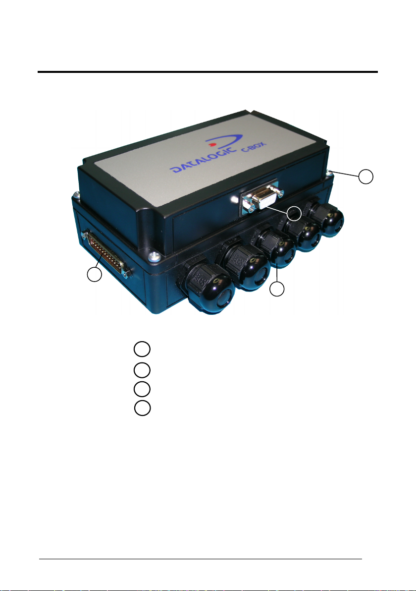
GENERAL VIEW
1
C-BOX 300
Figure A
25-pin scanner connector
1
3
4
2
Compression connectors
2
Cover screws (4)
3
Profibus connector
4
v
Page 8
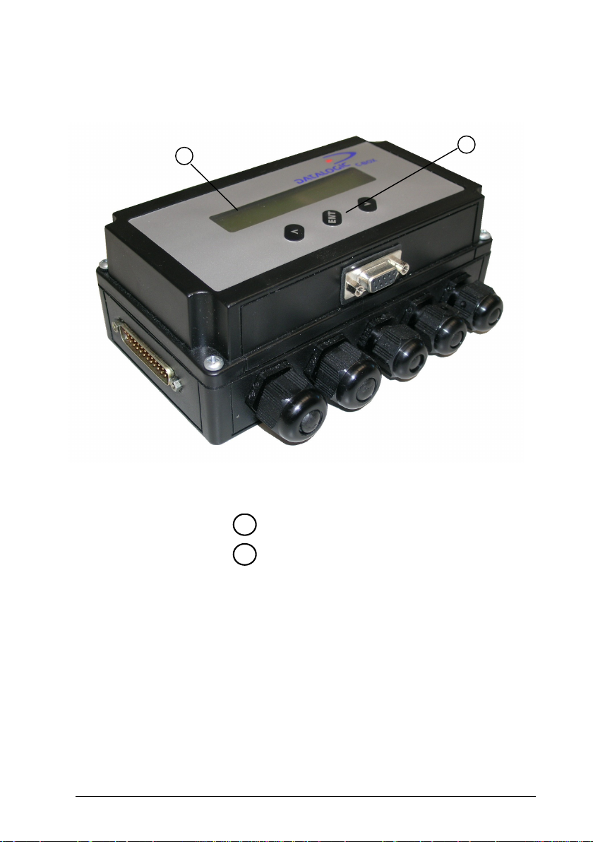
C-BOX 310
1
Figure B
LCD display
1
Keypad
2
2
vi
Page 9
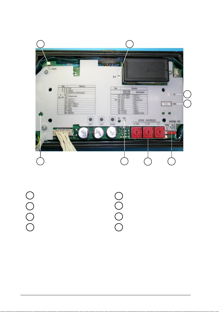
C-BOX 300/310
2
1
LCD contrast trimmer*
1
3
8
Figure C - Cover Inside
Module status LEDs
5
4
5
7
6
Power on LED
2
BUS activity LED
3
Tx LED
4
* For 310 models only
vii
Configuration switch
6
Node address selectors
7
Warning LED
8
Page 10
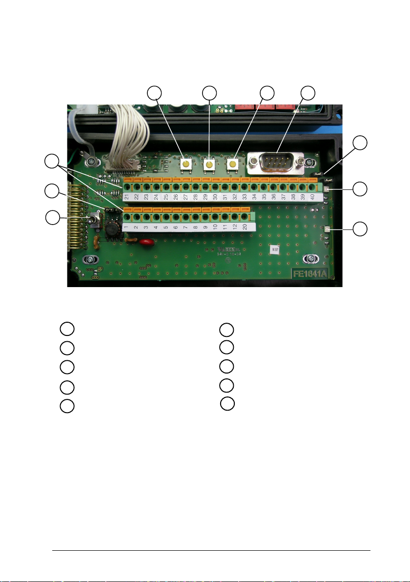
A
C-BOX 300/310
3
4
5
6
7
8
2
1
Figure D - Bottom Inside
Power on switch
1
Scanner grounding selector
2
Spring clamp terminal blocks
3
GET button
4
TEST button
5
SEND button
6
uxiliary port connector
7
OM4000 jumpers
8
Warning LED
9
Power polarity error LED
10
9
10
viii
Page 11

SAFETY PRECAUTIONS
POWER SUPPLY
ATTENTION: READ THIS INFORMATION BEFORE INSTALLING THE PRODUCT
- This product is intended to be installed by Qualified Personnel only.
The C-BOX 3X0 is intended to be supplied either by a UL Listed NEC Class 2 power
source, or a UL Listed ITE Limited Power Source (LPS), rated 10-30 V dc, minimum
0.5 A.
See par. 2.4.1 for correct power supply connections.
SAFETY NOTES
Observe the general rules for PROFIBUS components when planning the C-BOX
installation.
Please observe the following to avoid risk to personnel and damage to equipment
and to ensure that the C-BOX 3X0 functions correctly:
Safety Regulations Observe the guidelines in the VDE 0100 regulations for
handling electrical components,
Observe the applicable safety and accident prevention
regulations.
The C-BOX must only be installed or uninstalled by
qualified technical personnel with appropriate electrotechnical qualifications.
PROFIBUS Standard Observe the guidelines in the PROFIBUS standard
EN 50 170.
Bus Cable Bus wiring should only take place using special shielded,
twisted pair PROFIBUS cable. The high data transfer
rates can only be guaranteed with the correct cable type.
Cable Lengths Refer to the manual for the DP master for information on
maximum cable lengths for PROFIBUS.
ix
Page 12

Terminating Resistors Terminating resistors must be used if the C-BOX is
installed at the beginning or end of the PROFIBUS cable
segment. In this case, it is recommended to use
PROFIBUS connectors which contain an integrated
terminating resistor. It is recommended to use connectors
from ERNI and Siemens. If the bus is incorrectly
terminated, this can lead to errors in data transfer or to
damage to other stations on the bus.
Bus Connectors It is recommended to use only commercially available
PROFIBUS connectors for connecting the bus. It is
recommended to use connectors from ERNI and Siemens.
Cable Shield Shielded cables are less sensitive to interference due to
electromagnetic fields. With shielded cables, the
interference currents are led to ground through the
shielding rail, which is electrically connected to the case.
To ensure that the interference currents which flow
through the shielding do not themselves interfere with
other devices, it is important to provide a low impedance
connection to the protective ground. Observe the following
rules for the shields of the PROFIBUS cable and the serial
interface cable:
– The braiding of the shielding should have a
degree of coverage of more than 80%.
– The shielding should include a braided shield and
should not consist solely of foil shielding, since
the latter can be easily damaged by cable tension
and pressure.
– To ensure good immunity to interference at high
frequencies as well, the shielding of the cable
should be attached to the shielding rail at both
ends of the cable.
When connecting up the C-BOX 3X0, it is recommended to observe the guidelines in
the VDE 0100 regulations for handling electrical equipment.
WEEE COMPLIANCE
x
Page 13

GENERAL FEATURES
1
1 GENERAL FEATURES
1.1 DESCRIPTION
The C-BOX 3X0 is a connection box which converts RS232 communications to
Profibus. It is available in two models:
C-BOX 300, without display,
C-BOX 310, with LCD display.
It can be used as an accessory of the Datalogic scanners to perform the following
functions:
• Connect an RS232 scanner/reader to a Profibus network.
• Facilitate the connection of the scanner signals using a spring clamp connector.
• Get the scanner configuration and store it in memory. *
• Force the scanner to the Test operating mode. *
• Send the configuration stored in memory to the scanner. *
• In the C-BOX 310, visualize the data packet sent by the scanner on the LCD.
The C-BOX 300 / C-BOX 310 mechanical dimensions are 167 x 115 x 61 mm (6.57 x
4.53 x 2.40 in.). The C-BOX 300 weighs about 440 g (15.50 oz); the C-BOX 310
weighs about 500 g (17.60 oz).
Electrical connection is provided through spring clamp terminal blocks inside the CBOX 3X0.
The scanner is connected to the C-BOX 3X0 through a 25-pin connector placed on
the left side of the housing.
A 9-pin connector placed inside the C-BOX 3X0 facilitates connection between an
external PC and the auxiliary serial interface of the scanner.
The external 9-pin female connector is used to connect the C-BOX 3X0 to a Profibus
network.
* Function not compatible with Matrix-2000™ or Matrix-1000™.
1
Page 14

2
C-BOX 300/310
2 INSTALLATION
2.1 PACKAGE CONTENTS
Verify that the C-BOX 3X0 and all the parts supplied with the equipment are present
and intact when opening the packaging; the list of parts includes:
1) C-BOX 3X0
2) Installation manual
3) C-BOX 3X0 configuration CD-ROM
4) 2 mounting screws
2
1
Figure 1 - C-BOX 3X0 Package Contents
3
4
2
Page 15

INSTALLATION
2
2.2 OPENING THE DEVICE
To install the C-BOX 3X0 or during normal maintenance, it is necessary to open it by
unscrewing the four cover screws:
The C-BOX 3X0 must be disconnected from the power supply
during this operation.
CAUTION
Figure 2 - Opening the C-BOX 3X0
It is possible to perform the following operations:
• Proceed with the cable connections (see paragraph 2.4.2).
• Set the Profibus node address selection on the rotary switches.
• Mount the C-BOX 3X0 to a wall or panel.
3
Page 16

2
C-BOX 300/310
2.3 MECHANICAL INSTALLATION
The diagram below gives the overall dimensions of the C-BOX 3X0 and may be used
for its installation.
Ø3
[Ø0.14] n°2
66
[2.60]
= =
=
150
[5.91]
165
[6.48]
=
99
[3.88]
60
[2.36]
115
[4.53]
90
[3.54]
mm
inch
Figure 3 - Overall Dimensions
4
Page 17

INSTALLATION
2
C-BOX 3X0 can be installed to operate in different positions. The two screw holes
inside the housing of the C-BOX 3X0 are for mechanical fixture (Figure 4).
To mount the C-BOX 3X0:
1) Open the C-BOX 3X0 by unscrewing the 4 cover screws. If necessary, using the
two mounting holes inside the device as a pattern, mark the panel with an
appropriate object and then drill two holes in the panel.
2) Align the C-BOX 3X0 and insert two screws and screw them into the panel until
tight (see Figure 4).
Figure 4 - Mounting C-BOX 3X0
5
Page 18

2
C-BOX 300/310
2.4 ELECTRICAL CONNECTIONS AND HARDWARE SETUP
The following figure shows the typical layout.
PROFIBUS
C-BOX 3X0
SCANNER
System
Cables
Figure 5 – System Layout
Matrix readers are not compatible with the WinHost configuration
program. For Matrix reader setup first read par. 2.9 for details.
NOTE
A PC can be connected to the C-BOX 3X0 (and consequently to the scanner
auxiliary interface) through the internal 9-pin connector. This allows monitoring of the
data transmitted by the scanner or configuration through the WinHost utility (see the
scanner Installation Manual for more details). The scanner auxiliary interface signals
are also available on the internal spring clamp connectors.
After making system cabling and switch settings (see sub-paragraphs under 2.4 and
2.5), connect the scanner to the 25-pin connector on the left side of the C-BOX 3X0
housing.
Switch ON the C-BOX 3X0 power switch (see Figure 6).
By default, after power on, an automatic connection procedure takes place between
the C-BOX 3X0 and the scanner. During this phase, requiring a few seconds, the
warning LED is turned ON. Once the procedure had been completed successfully,
the warning LED is turned OFF.
MASTER
6
Page 19

INSTALLATION
2
Autoconnection is not compatible with Matrix readers and must be
disabled in the C-BOX 3x0 configuration. See par. 2.9 for details.
NOTE
To disable this automatic connection procedure, refer to WinHost Help Online.
After system functioning has been verified, close the C-BOX 3X0 using the 4 cover
screws making sure the rubber seal is fitted correctly between the parts of the
housing.
2.4.1 Power Supply
Power is supplied to the C-BOX 3X0 through the pins provided on the spring clamp
connector.
The power switch (see Figure 6) switches the power supply ON or OFF for both the
C-BOX 3X0 and the connected scanner.
S1
ON
OFF
Figure 6 - Power Switch ON/OFF Positions
C-BOX
VS
1
GND
2
USER INTERFACE
V+ (10 - 30 Vdc)
GND
Figure 7 - Power Supply Connections
The power supply must be between 10 and 30 Vdc only.
7
Page 20

2
NOTE
WARNING
NOTE
C-BOX 300/310
Pin 1 is also electrically connected to pins 3 and 5, just as pin 2 is
electrically connected to pins 4 and 6. This is useful for external
trigger/inputs connections.
Incorrect grounding of the C-BOX 3X0 can injure personnel and
damage equipment. Make sure that the C-BOX is correctly grounded.
The C-BOX 3X0 is protected against polarity reversal, a red LED signals
this condition. When this condition occurs, all other C-BOX LEDs will be
off until the power feed is connected with correct polarity.
8
Page 21

INSTALLATION
2
2.4.2 System Wiring
The connection and wiring procedure for C-BOX 3X0 is described as follows:
1) Open the C-BOX 3X0 as described in paragraph 2.2.
2) Verify that the C-BOX 3X0 power switch is off (see Figure 6).
3) Unscrew the compression connectors and pass all the system cables
through them into the C-BOX 3X0 housing.
4) To connect the power and input/output signals:
• Prepare the individual wires of the system cables by stripping the
insulation back approximately 1 cm.
• Using a device such as a screwdriver, push down on the lever directly
next to the clamp (see Figure 8).
• Insert the wire into the clamp and release the lever.
The wire will now be held in the spring clamp.
Figure 8 - System Cable Connections
The wiring used can be solid or stranded but must meet the following specifications.
All positions: 24 - 16 AWG 0.2 - 1.5 mm²
9
Page 22

2
C-BOX 300/310
The C-BOX 3X0 spring clamp connector pinouts are indicated in the following table.
Refer to the scanner Installation Manual for details.
Pin Name
1, 3, 5 VS
2, 4, 6 GND
7, 8 EARTH GROUND
9…12, 20, 33, 34, 40 Reserved
35 TXA
37 RXA
21 OUT1+ OUT1+ OUT1+ NC
22 OUT REF OUT1- OUT1- NC
23 OUT2+ OUT2+ OUT2+ NC
24 OUT REF OUT2- OUT2- NC
25 NC Reserved OUT3+ OUT3+
26 NC Reserved OUT3- OUT327 EXT TRIG+ EXT TRIG+ EXT TRIG A EXT TRIG A
28 EXT TRIG- EXT TRIG- EXT TRIG B EXT TRIG B
29 NC IN1+ IN 2A NC
30 NC IN1- IN 2B NC
31 NC IN2+ NC NC
32 NC IN2- NC NC
36 RTSA GND NC NC
38 CTSA SGND AUX GND GND
39 SGND SGND GND GND
DS2100A
DS2400A
DS4600A Matrix-2000™ Matrix-1000™
10
NOTE
Pin 7 or 8 should be connected to the earth ground.
Pins 13… 19 are not present in the C-BOX 3X0 models.
Page 23

INSTALLATION
2
2.4.3 Scanner Chassis Grounding Jumper Settings
The scanner chassis grounding method can be selected by positioning a jumper (see
Figure 9). In this way the scanner chassis can be connected to earth ground (only if
pins 7 or 8 are connected to a good earth ground) or to the power supply ground
signal. The scanner chassis can also be left floating but, in this case, the jumper
must be removed.
to EARTH
GROUND
Figure 9 – Chassis Grounding
(default)
floating to GND
The C-BOX 3X0 is now installed which completes the electrical connections for your
scanning system.
2.4.4 OM4000 Jumper Settings
Figure 10 - OM4000 Jumpers
The jumpers allow connection to the EXT TRIG signals on separate spring clamp
terminals for applications which use the OM4000 Oscillating Mirror in Trigger Mode.
They are used together and they have the following significance:
when a jumper is in the J1 position (see Figure above) pin 40 is connected to pin 27
(EXT TRIG+); a jumper in J2 position connects pin 20 to pin 28 (EXT TRIG-).
If the jumpers are removed pin 20 and pin 40 are disconnected.
J1
J2
11
Page 24

2
C-BOX 300/310
2.5 PROFIBUS CONNECTIONS AND SETUP
2.5.1 Profibus Node Address Selection
To interface the C-BOX 3X0 with a Profibus network, the Node Address should be
set using the rotary switches placed in the cover inside.
The valid address range is from 000 to 126.
If an invalid value is detected, the C-BOX cannot communicate with the Profibus
network.
The Node Address can also be assigned through WinHost. Refer to Help on-Line.
HUNDREDS
Figure 11 - Rotary Switches
TENS UNITS
2.5.2 Profibus Connector (9-Pin Female External Connector)
To connect C-BOX 3X0 as a Profibus DP Slave, use a standard Siemens Profibus
cable with a 9-pin male connector (see DIN 19245 part 1) and plug it into the 9-pin
female external connector.
5
1
9
6
12
Page 25

INSTALLATION
9-pin external female connector pinout
Pin Name Function
1 N.C. not connected
2 N.C. not connected
3 B-LINE (RS485+)
4 RTS Ready To Send
5 GND RS485 Bus Reference
6 + 5V (galvanically isolated) RS485 Bus Power Supply
7 N.C. not connected
8 A-Line (RS485-)
9 N.C. not connected
2
2.5.3 Connection to a Profibus Network
The following figure shows a Profibus layout with C-BOX 3X0 devices connected to a
Profibus Master:
PROFIBUS DP
Master
Profibus DP
Slave node #1
Profibus DP
Slave node #2
Figure 12 - Profibus Connection
Profibus DP
Slave node #n
C-BOX 3X0
It is recommended to use only commercially available PROFIBUS connectors for
connecting to the bus. Use connectors from ERNI and Siemens. If the C-BOX is
installed at the beginning or end of the PROFIBUS cable segment, it is
recommended to use PROFIBUS connectors, which contain an integrated
terminating resistor.
13
Page 26
2
C-BOX 300/310
To ensure that the C-BOX functions without errors, the shield of the PROFIBUS
cable must be grounded.
– Ensure that the PROFIBUS connector uses the pin assignments shown in par
2.5.2
– Attach the PROFIBUS connector to the PROFIBUS interface socket on the
C-BOX 3X0 and secure the connector with the retaining screws.
– For C-Box 310 models, it is advised to use up to two ferrites (type Stewart
28A2029-0A0) on the Profibus cable to reduce electrical noise.
2.5.4 C-BOX 3X0 Configuration for Profibus DP Slave Node
In order to setup the C-BOX 3X0, you need to install the function blocks in your PLC
programming software and configure it.
The procedure below can be generally applied for this purpose:
1. Start the PROFIBUS configurator on the DP Master.
2. Insert the CD with the device database files (.GSD) into the drive of the
programming device (usually a PC).
3. Load the .GSD file HMS_1810.GSD in the configurator.
4. Configure the C-BOX 3X0 (through WinHost) setting the parameters according
to the PROFIBUS network application as described in the configurator's Help
On-Line or User's Manual.
Further information on PROFIBUS protocol and Flow control is
provided in the C-BOX 300/310 PROFIBUS document and Help OnLine installed from the configuration CD provided in the C-BOX
NOTE
package.
14
Page 27

INSTALLATION
2
2.6 CONFIGURATION SWITCH AND 9-PIN INTERNAL CONNECTOR
The 9-pin internal connector may have two different functions according to the
position of the configuration switch.
Figure 13 - Configuration Switch and 9-pin Male Connector
POSITION MODE
Normal Operation (default): In this position, the C-BOX 3X0 is in the
normal operating mode. It communicates with the scanner through
the 9-pin internal connector and the scanner auxiliary serial interface.
The internal connector pinout is illustrated in the following table:
9-pin C-Box 3x0 connector pinout in Normal mode
Pin Name
1 NC
2 RXA
3 TXA
4 NC
6 NC
9 NC
5 SGND SGND GND GND
7 CTSA SGND AUX GND GND
8 RTSA GND NC NC
DS2100A
DS2400A
DS4600A Matrix-2000™ Matrix-1000™
15
Page 28
2
C-BOX 300/310
POSITION MODE
CFG: When the switch is in this position, the C-BOX 3X0 is in
configuration mode. The communication with the scanner is interrupted
and pins 2 and 3 are no longer dedicated to the scanner auxiliary
interface but to the C-BOX 3X0 configuration (see table below). The
system enters configuration mode and waits to be configured through
WinHost (see WinHost Help On Line).
The C-BOX 310 display visualizes an appropriate message.
Once the C-BOX 3X0 configuration is completed, it is necessary to
replace the switch in the Normal Operation position. At the end of the
reboot phase, the C-BOX 3X0 is ready to function with the new
configuration.
9-pin C-Box 3x0 connector pinout in Configuration mode
Pin Name Function
2 RX C-BOX 3X0 Configuration
3 TX C-BOX 3X0 Configuration
5 SGND Signal Ground
When the C-BOX 3X0 configuration is completed, remember to
replace the Configuration switch in the Normal Operation position.
CAUTION
16
Page 29

INSTALLATION
2
2.7 SCANNER REQUIREMENTS
The C-BOX 3X0 can be connected to the following scanners through the 25-pin
connector illustrated in Figure A.
DS2100A DS4600A *Matrix-2000™
DS2400A *Matrix-1000™
1) For all scanners, it is necessary to use the RS232 interface which must be
selected by the user.
2) At least one Terminator Character should be enabled in the connected scanner
(see the Terminator parameters in the Data Format section of the Help On Line).
The device address must be pre-set using one of the methods described in par.
2.5.1.
* For Matrix reader compatibility issues, refer to par. 2.9.
2.8 OPERATING MODES
With the C-BOX 3X0, three operating modes are possible:
Normal Operation: Once the connection procedure is completed (the warning LED
is OFF), the C-BOX 3X0 is ready to receive code strings from the scanner's RS232
main interface. Then, it converts them to the Profibus DP network.
GET/TEST/SEND: Through the C-BOX 300 internal buttons and the C-BOX 310
external keypad, it is possible to communicate with the scanner to perform one of the
following functions:
• Get scanner configuration
• Force the scanner in TEST mode
• Send a configuration to the scanner
At the end of each function the scanner returns to the previous operating mode.
Configuration (CFG): When the CFG switch is in CFG position (left) it is possible to
configure the C-BOX 3X0 parameters.
17
Page 30

2
C-BOX 300/310
2.8.1 GET/TEST/SEND Functions
The C-BOX 300 has three internal function buttons. In the C-BOX 310, they are also
available on the cover, and their function is indicated on the display.
C-BOX 300
GET TEST SEND
C-BOX 310
Figure 14 – Internal Function Buttons
The GET/TEST/SEND function is not compatible with Matrix readers.
NOTE
The procedure to enable the GET/TEST/SEND function is the following:
1. Press both the left and right buttons at the same time for at least one second;
the warning LED is turned ON.
2. Release the buttons.
3. Press the left button corresponding to the GET function, the center button
corresponding to the TEST function or the right button corresponding to the
SEND function.
18
Page 31

INSTALLATION
GET – (left button): the C-BOX 3X0 reads the current scanner configuration and
2
permanently copies it in its own memory support (EEPROM). The C-BOX
3X0 preserves this configuration also when switched off.
TEST - (center button): the C-BOX 3X0 forces the scanner to run the Test
Operating Mode (refer to the scanner Installation Manual for details).
Press any button to quit the Test Operating Mode and restore the scanner
normal operating mode.
SEND - (right button): the C-BOX 3X0 sends the configuration previously stored in
its own permanent memory support to the scanner’s EEPROM.
Once the buttons are released in step 1, a ten-second timeout starts.
If no button is pressed within this time (no function is selected), the
procedure will be cancelled.
NOTE
The C-Box 300 warning LED (Figure 16) is turned OFF at the end of
each procedure.
The C-BOX 310 display visualizes self-explaining messages about
GET/TEST/SEND functions.
19
Page 32

2
2.8.2 LED Indicators
In the C-BOX 3X0 the Warning LED is repeated in the bottom inside.
Power on
BUS activity
Figure 15 - LED Indicators
Warning LED
C-BOX 300/310
TX LED
MS LEDs
20
Warning
LED
Power polarity
error
LED
Figure 16 – Warning LED
Page 33

INSTALLATION
2
The internal LEDs of the C-BOX 3X0 (see Figure 15) indicate the following:
POWER ON (PWR) (red) indicates the C-BOX 3X0 is connected to the power
supply and the power switch is ON.
WARNING (WL) (red) indicates a warning or error condition. It is ON when
a connection procedure is in progress (the system is
busy), during a GET/TEST/SEND procedure or during the
Configuration Mode. It blinks when an error condition
occurs. Normally this LED should be OFF.
BUS ACTIVITY (BA) (green) indicates the Profibus Network activity. When
communication takes place, this LED will blink slightly.
TRANSMISSION (TX) (green) indicates there is communication between the
Application and the DeviceNet module. Upon
communication, this LED will blink slightly.
MODULE STATUS (MS) (green) OFF = Bus off-line or power not supplied.
ON = Bus in Data Exchange Mode.
Flashing = Bus in Clear Mode.
(red) OFF = No error or power not supplied.
ON = Error in initialisation of Profibus ASIC.
Flashing = Error in configuration data and / or in
user parameter data.
POWER POLARITY ERROR (red) indicates a wrong polarity. While activated, all other
LEDs will be off until the power feed is connected with
correct polarity.
21
Page 34

2
C-BOX 300/310
2.9 SPECIAL NOTES FOR MATRIX READER SETUP
When connected to a C-BOX 3x0 through the 25-pin connector, the
9-pin Auxiliary port connector on the Matrix reader cannot be used
for communication (i.e. configuration through VisiSet™). The Matrix
reader can only be configured through the 9-pin connector inside
CAUTION
the C-BOX 3x0 and the C-BOX 3x0 must first be configured. see
the following paragraphs for details.
2.9.1 Preparing C-Box 3x0 for Matrix Reader Communication
This paragraph describes how to configure a C-BOX 3x0 so that a Matrix reader can
communicate through the C-Box3x0 and also be configured through its Auxiliary
RS232 interface.
1. Open the C-BOX 3x0;
2. Move the Configuration Switch from the Normal Operation to the CFG position;
3. Connect the 9-pin internal connector of the C-BOX 3x0 to the PC (using a
crossover cable) and run the Winhost™ configuration tool;
4. Select the Connect option to open communications with the C-BOX 3X0 and
wait until the correct communication speed has been determined;
5. From the SCANNER INTERFACE menu, set Auto Connect: Disabled and verify
Data Source: Main Interface and save the configuration to the C-Box 3x0 (refer
to Figure 17);
Figure 17 – WinHost Configuration Menu for C-Box 3x0
6. Return the Configuration Switch to the Normal Operation position.
22
Page 35

INSTALLATION
2
2.9.2 Matrix Reader Configuration Using VisiSet™
After performing C-Box 3x0 configuration as described in the previous paragraph, the
Matrix reader can be configured
connected to the PC using the VisiSet™ configuration program:
1. Run the VisiSet™ configuration tool and select Connect to communicate with
the Matrix reader;
2. Configure the reader and save the configuration;
3. Select Disconnect and close the VisiSet™ configuration tool;
4. For Matrix-2000™ the configuration is complete, close the C-BOX 3x0.
For Matrix-1000™ follow the instructions in the following paragraph to complete
the configuration.
through the C-Box 3x0 9-pin internal connector
2.9.3 Completing C-Box 3x0 Configuration for Matrix-1000™
Readers
When connected to a C-BOX 3x0/4x0, Matrix-1000™ can only
communicate through its Auxiliary Interface.
CAUTION
Once Matrix-1000™ has been configured through VisiSet™ as described in the
previous paragraph, to complete the configuration procedure the C-Box 3x0 must be
reconfigured to accept data from the Matrix-1000™ reader through its Auxiliary
RS232 interface (the only RS232 interface available).
1. Move the C-Box 3x0 Configuration Switch from the Normal Operation to the
CFG position;
2. Connect the 9-pin internal port of the C-BOX 3X0 to the PC (using a crossover
cable) and run the Winhost™ configuration tool;
3. Select the Connect option to open communications with the C-BOX 3X0 and
wait until the correct communication speed has been determined;
4. From the SCANNER INTERFACE menu, set Data Source: Aux Interface and
save the configuration to the C-Box 3x0 (refer to Figure 18);
5. Return the Configuration Switch to the Normal Operation position;
23
Page 36

2
Figure 18 – WinHost Configuration Menu for C-Box 3x0
6. Close the C-BOX 300.
C-BOX 300/310
24
Page 37

TECHNICAL FEATURES
3
3 TECHNICAL FEATURES
ELECTRICAL FEATURES
Power
Supply voltage 10 to 30 Vdc
Power consumption max. 2.9 W + scanner 4.7 W + scanner
USER INTERFACE
LED indicators Power ON, Warning,
Tx, Diagnostics
PHYSICAL FEATURES
Mechanical dimensions 167 x 115 x 61 mm (6.57 x 4.53 x 2.40 in.)
Weight about 440 g. (15.51 oz.) about 500 g. (17.63 oz.)
SOFTWARE FEATURES
Parameter storage Non-volatile internal memory
PROFIBUS INTERFACE
Interface type
Data transfer rate
ENVIRONMENTAL FEATURES
Operating temperature
Storage temperature
Humidity max. 90% non condensing
Vibration resistance
IEC 68-2-6 test FC
Shock resistance
IEC 68-2-27 test EA
Protection class
C-BOX 300 C-BOX 310
RS485
bit/s 9600, 19200, 93750, 187500, 0.5M,
1.5M, 3M, 6M, 12M, automatic detection of
the data transfer rate
-10 to 50 °C (14 to 122 °F)
-20 to 70 °C (-4 to 158 °F)
14 mm @ 2 to 10 Hz;
1.5 mm @ 13 to 55 Hz;
2g @ 70-200 Hz
2 hours on each axis
30g; 11 ms;
3 shocks on each axis
IP64
(when correctly connected to the scanner)
The features given are typical at a 25 °C ambient temperature (if
not otherwise indicated).
NOTE
25
Page 38

dichiara che
declares that the
déclare que le
bescheinigt, daß das Gerät
declare que el
C-BOX-3X0 e tutti i suoi modelli
and all its models
et tous ses modèles
und seine Modelle
y todos sus modelos
sono conformi alle Direttive del Consiglio Europeo sottoelencate:
are in conformity with the requirements of the European Council Directives listed below:
sont conformes aux spécifications des Directives de l'Union Européenne ci-dessous:
der nachstehend angeführten Direktiven des Europäischen Rats:
cumple con los requisitos de las Directivas del Consejo Europeo, según la lista siguiente:
89/336/EEC EMC Directive e 92/31/EEC, 93/68/EEC emendamenti successivi
and further amendments
et ses successifs amendements
und späteren Abänderungen
y succesivas enmiendas
Basate sulle legislazioni degli Stati membri in relazione alla compatibilità elettromagnetica ed alla sicurezza
dei prodotti.
On the approximation of the laws of Member States relating to electromagnetic compatibility and product
safety.
Basée sur la législation des Etats membres relative à la compatibilité électromagnétique et à la sécurité des
produits.
Über die Annäherung der Gesetze der Mitgliedsstaaten in bezug auf elektromagnetische Verträglichkeit und
Produktsicherheit entsprechen.
Basado en la aproximación de las leyes de los Países Miembros respecto a la compatibilidad
electromagnética y las Medidas de seguridad relativas al producto.
Questa dichiarazione è basata sulla conformità dei prodotti alle norme seguenti:
This declaration is based upon compliance of the products to the following standards:
Cette déclaration repose sur la conformité des produits aux normes suivantes:
Diese Erklärung basiert darauf, daß das Produkt den folgenden Normen entspricht:
Esta declaración se basa en el cumplimiento de los productos con las siguientes normas:
EN 55022 (CLASS A ITE), August 1994:
A
MENDMENT A1 (CLASS A ITE), October 2000
EN 61000-6-2, October 2001:
DATALOGIC S.p.A.,
Via Candini, 2
40012 - Lippo di Calderara
Bologna - Italy
LIMITS AND METHODS OF MEASUREMENTS OF RADIO DISTURBANCE
CHARACTERISTICS OF INFORMATION TECHNOLOGY EQUIPMENT
ELECTROMAGNETIC COMPATIBILITY (EMC).
P
ART 6-2: GENERIC STANDARDS – IMMUNITY FOR INDUSTRIAL
ENVIRONMENTS
05
Lippo di Calderara, 08/09/2005
Ruggero Cacioppo
Quality Assurance Laboratory Manager
 Loading...