

Page 1

Falcon® 4400 Series
Falcon 4410
52-Key NU model
Falcon 4410
26-Key model
Falcon 4420
48-Key model
with Windows® CE
Product Reference Guide
Page 2

Datalogic Mobile, Inc
1505 Westec Dr.
Eugene, Oregon 97402
Telephone: (541) 743-4800
Fax: (541) 743-4900
An Unpublished Work - All rights reserved. No part of the contents of this documentation or the procedures
described therein may be reproduced or transmitted in any form or by any means without prior written permission of
Datalogic Mobile, Inc. or its affiliates or subsidiaries ("Datalogic" or “Datalogic Mobile”) . Owners of Datalogic products are hereby granted a non-exclusive, revocable license to reproduce and transmit this documentation for the
purchaser's own internal business purposes. Purchaser shall not remove or alter any proprietary notices, including
copyright notices, contained in this documentation and shall ensure that all notices appear on any reproductions of
the documentation.
Should future revisions of this manual be published, you can acquire printed versions by contacting your Datalogic
representative. Electronic versions may either be downloadable from the Datalogic Mobile website
(www.mobile.datalogic.com) or provided on appropriate media. If you visit our website and would like to make
comments or suggestions about this or other Datalogic publications, please let us know via the “Contact Datalogic”
page.
Disclaimer
Datalogic has taken reasonable measures to provide information in this manual that is complete and accurate,
however, Datalogic reserves the right to change any specification at any time without prior notice.
Datalogic is a registered trademark of Datalogic S.p.A. and the Datalogic logo is a trademark of Datalogic S.p.A. all
licensed to Datalogic Mobile, Inc. All other trademarks and trade names referred to herein are property of their
respective owners.
®
Falcon
Microsoft Windows
is a registered trademark of Datalogic Mobile, Inc. and its affiliates and subsidiaries.
®
, Windows® 2000, Windows® CE, Windows® NT, and Windows® XP are registered trade-
marks of Microsoft Corporation.
Patents
This product may be covered by one or more of the following patents:
4,861,972 • 4,866,257 • 4,879,456 • 5,198,649 • 5,208,449 • 5,212,372 • 5,247,161 •
5,311,000 • 5,440,110 • 5,481,098 • 5,493,108 • 5,508,505 • 5,664,231 • 5,671,374 •
5,686,716 • 6,041,374 • 6,412,698 • 6,415,978 • 6,454,168 • 6,478,224 • 6,513,714 •
6,536,670 • 6,561,427 • 6,585,157 • 6,923,377 • 7,108,170 • D377345 • CA2,188,399 • Other
U.S. and Foreign Patents Pending.
Page 3

Table of Contents
Preface: About this Guide .................................................................................. vii
Chapter 1. Batteries and Power ........................................................................ 1-1
Overview ................................................................................................................... 1-1
Suspend Mode ............................................................................................................1-1
Suspending .......................................................................................................... 1-1
Resuming ............................................................................................................1-2
Battery Warnings and Cautions ..................................................................................... 1-2
Battery Disposal ........................................................................................................1-4
Chapter 2. Configuring the Falcon..................................................................... 2-1
Overview ................................................................................................................... 2-1
Backlight ................................................................................................................... 2-2
Bluetooth Manager ...................................................................................................... 2-4
Search for device ..................................................................................................2-4
Connect to a Bluetooth Device ................................................................................ 2-4
Viewing or Deleting Paired Devices ..........................................................................2-6
Settings ............................................................................................................... 2-7
Certificates ................................................................................................................. 2-8
Date and Time ............................................................................................................ 2-8
Decoding ................................................................................................................... 2-9
Configuration Control Panels ................................................................................... 2-9
Settings ............................................................................................................. 2-15
Display Configuration ................................................................................................. 2-15
Background ........................................................................................................ 2-15
Appearance ........................................................................................................ 2-16
Falcon Config ............................................................................................................ 2-16
Imager .................................................................................................................... 2-16
Imaging Overview ............................................................................................... 2-16
Image Capture ................................................................................................... 2-17
Image File ......................................................................................................... 2-18
Image Size ........................................................................................................ 2-19
Image Settings ................................................................................................... 2-20
Sample Imager Settings ...................................................................................... 2-20
Input Panel Properties ............................................................................................... 2-21
Internet Options ....................................................................................................... 2-22
Keyboard Configuration ............................................................................................. 2-25
26-Key Keypad ................................................................................................... 2-25
48, 52 and 52-Key NU Keypads ............................................................................ 2-25
Product Reference Guide i
Page 4

Contents
Network and Dialup ................................................................................................... 2-27
Owner ..................................................................................................................... 2-28
Password ................................................................................................................. 2-28
PC Connection .......................................................................................................... 2-29
Persistent Registry .................................................................................................... 2-29
Power Configuration .................................................................................................. 2-30
Regional Settings ...................................................................................................... 2-31
Remove Programs ..................................................................................................... 2-32
Storage Properties .................................................................................................... 2-32
Stylus Calibration ...................................................................................................... 2-33
System Properties .................................................................................................... 2-35
General Tab ...................................................................................................... 2-35
Firmware Tab .................................................................................................... 2-35
Memory Configuration ......................................................................................... 2-36
Device Name ...................................................................................................... 2-37
Copyrights ......................................................................................................... 2-37
Volume and Sounds ................................................................................................... 2-38
Wi-FI ....................................................................................................................... 2-39
About the Summit Client Utility ............................................................................. 2-39
SCU Windows ..................................................................................................... 2-39
Chapter 3. Software Applications ..................................................................... 3-1
Overview ...................................................................................................................3-1
Inbox ........................................................................................................................3-2
Internet Explorer ........................................................................................................3-3
Media Player ...............................................................................................................3-4
WordPad ....................................................................................................................3-4
Installing Programs .....................................................................................................3-5
Using an Installation Wizard ...................................................................................3-5
Installing Programs Manually ..................................................................................3-5
Using Windows Explorer to Add to the Start Menu .....................................................3-6
Using ActiveSync to Add to the Start Menu ...............................................................3-7
Removing Programs ....................................................................................................3-7
Firmware Update Utility ................................................................................................3-7
Retrieving a Firmware Image Update .......................................................................3-8
Installing FUU on the Host PC .................................................................................3-8
Updating the Falcon Firmware .................................................................................3-9
Restoring Falcon Firmware ...................................................................................3-10
AutoStart ................................................................................................................. 3-12
Installing CAB files .............................................................................................. 3-13
Autostart.ini ....................................................................................................... 3-14
Chapter 4. Networks, Communications, and Connections ................................. 4-1
Overview ...................................................................................................................4-1
Installing & Setting Up Microsoft ActiveSync ...................................................................4-1
Installing Microsoft ActiveSync ................................................................................4-2
Setting Up ActiveSync ...........................................................................................4-4
ii
Falcon® 4400 Series with Windows® CE
Page 5

Contents
Installing the USB Driver ..............................................................................................4-5
Using ActiveSync ........................................................................................................4-6
File Synchronizing using ActiveSync ........................................................................4-6
Networking ................................................................................................................4-8
Setting Up the Network ID .....................................................................................4-8
The Network Icon ................................................................................................. 4-8
Network and Dialup Connections .............................................................................4-9
SNMP ........................................................................................................................ 4-9
Appendix A. Accessories .................................................................................. A-1
Overview ...................................................................................................................A-1
Power Supplies ...........................................................................................................A-2
Battery Pack ........................................................................................................A-2
Single-Slot Dock ...................................................................................................A-2
Four-Slot Dock .....................................................................................................A-3
Battery Charger ....................................................................................................A-3
USB Cable ............................................................................................................A-4
Serial Charging Cable ............................................................................................A-4
Printer Cable ........................................................................................................A-4
Serial Printer Adapter ............................................................................................A-4
Holsters and Softcases .................................................................................................A-6
Holsters ..............................................................................................................A-6
Softcases .............................................................................................................A-7
Installing the Handle or Handstrap ................................................................................A-8
Installing the Handstrap on the Falcon 4420 .............................................................A-8
Installing a Handle on the Falcon 4410 .....................................................................A-9
Tethered Stylus ........................................................................................................ A-10
Installing a Tethered Stylus .................................................................................. A-10
Removing a Tethered Stylus ................................................................................. A-11
Appendix B. Falcon® Desktop Utility for Windows® CE ................................... B-1
Overview ...................................................................................................................B-1
Falcon Desktop Utility ..................................................................................................B-2
Administrative Options ...........................................................................................B-3
Setting a Password ................................................................................................B-4
Changing a Password ............................................................................................B-4
Removing a Password ............................................................................................B-4
Password Request Dialog Box .................................................................................B-4
Setting Hot Keys ..................................................................................................B-5
Internet Explorer Configuration ...............................................................................B-8
Modifying Windows Controls ................................................................................. B-10
Application Selector ................................................................................................... B-11
Add Application ................................................................................................... B-12
Application Selector ................................................................................................... B-14
Application Switcher User Interface ............................................................................. B-15
Product Reference Guide iii
Page 6

Contents
Appendix C. Configuring the Web Server.......................................................... C-1
Overview .................................................................................................................. C-1
Enabling the Web Server ............................................................................................. C-1
Setting Up a User ....................................................................................................... C-2
Testing the Web Server ............................................................................................... C-3
Launching the Network Administration Page ................................................................... C-4
Web Server Registry Settings ...................................................................................... C-4
Creating and Using an ISAPI Service ............................................................................. C-6
Appendix D. SNMP Interface ............................................................................ D-1
Overview .................................................................................................................. D-1
SNMP Concepts .................................................................................................... D-1
MIB Files ............................................................................................................. D-1
Additional Resources ............................................................................................ D-2
Appendix E. Cable & Connector Configurations................................................. E-1
Introduction ...............................................................................................................E-1
General Specifications ..................................................................................................E-1
Wire Requirements ................................................................................................E-1
Supply Voltage .....................................................................................................E-1
USB Cable ..................................................................................................................E-1
Serial Cable ................................................................................................................E-2
Printer Cable ..............................................................................................................E-2
Appendix F. Programming Parameters ............................................................. F-1
Overview ................................................................................................................... F-1
Programming Codes Without Parameters ........................................................................ F-2
Bar Code Parameters ................................................................................................... F-3
OCR Configuration ..................................................................................................... F-37
OCR Data Output ................................................................................................ F-37
OCR Templates ................................................................................................... F-37
OCR Check Characters ......................................................................................... F-42
Appendix G. Programming Bar Codes ............................................................... G-1
Overview .................................................................................................................. G-1
Predefined Defaults ................................................................................................... G-3
Codabar .................................................................................................................... G-3
Code 39 .................................................................................................................... G-5
Code 93 .................................................................................................................... G-8
Code 128 ................................................................................................................ G-10
EAN-13 ................................................................................................................... G-12
EAN-8 ..................................................................................................................... G-14
Interleaved 2 of 5 .................................................................................................... G-15
Matrix 2 of 5 ............................................................................................................ G-17
MSI ........................................................................................................................ G-19
Pharmacode 39 (Code 32) ......................................................................................... G-21
iv
Falcon® 4400 Series with Windows® CE
Page 7

Contents
RSS-14 ....................................................................................................................G-21
RSS Limited .............................................................................................................G-22
RSS Expanded ..........................................................................................................G-22
Standard 2 of 5 ........................................................................................................G-24
Trioptic ....................................................................................................................G-26
UPC-A .....................................................................................................................G-26
UPC-E ......................................................................................................................G-28
UPC/EAN Extensions ..................................................................................................G-29
2D Symbologies ........................................................................................................G-30
Aztec Code ...............................................................................................................G-30
DataMatrix ...............................................................................................................G-32
Composite ................................................................................................................G-34
Maxicode .................................................................................................................G-36
OCR ........................................................................................................................G-38
PDF-417 ..................................................................................................................G-39
MicroPDF-417 ...........................................................................................................G-41
QR Code ..................................................................................................................G-43
Imager Labels ..........................................................................................................G-45
Other Controls ..........................................................................................................G-45
Appendix H. Glossary....................................................................................... H-1
Index................................................................................................................. I-i
Product Reference Guide v
Page 8

Contents
NOTES
vi
Falcon® 4400 Series with Windows® CE
Page 9

How to Use this Manual
This Product Reference Guide contains comprehensive basic user
instructions for the Falcon 4400 Series mobile computer software,
batteries, dock, serial cable, data transfer, as well as advanced user
information such as bar code configuration and parameters. This section
of the manual provides an overview of the manual’s contents and
organization.
Document Overview
This document contains the following material:
• This Preface provides an overview of the contents for each chapter, and describes document style conventions.
•Chapter1, Batteries and Power, discusses checking battery power,
power conservation, battery installation, battery charging with a
dock or battery charger, battery storage, battery disposal, and
resetting the mobile computer.
Preface:
About this Guide
•Chapter2, Configuring the Falcon, uses the control panels to
adjust touchscreen calibration, date and time, display backlight/
contrast, volume/sounds, scanner, power, and memory.
•Chapter3, Software Applications, covers flash memory, install-
ing, selecting, using, and removing applications, entering data,
and using the soft input panel with Inbox, Internet Explorer, and
Word Pa d.
•Chapter4, Networks, Communications, and Connections,
describes installing, setting up, and using ActiveSync and Networking.
•AppendixA, Accessories, describes the Accessories, such as docks,
battery chargers, holsters, and soft cases available for the Falcon.
Product Reference Guide vii
Page 10

Preface
•AppendixB, Falcon® Desktop Utility (FDU) allows Windows
®
administrators to configure Windows
CE Falcons to control
individual user access.
•AppendixC, Configuring the Web Server, describes configuring
the Falcon to work with a Web Server.
•AppendixD, SNMP Interface, describes SNMP (Simple Net-
work Management Protocol) concepts, MIB (Management Information Base) files, and provides additional resources.
•AppendixE, Cable and Connector Configurations contains
pinout information, to create standard interface cables for use in
interconnecting the Dock to power and/or peripheral devices.
•AppendixF, Programming Parameters, provides the programma-
ble settings for the Falcon.
•AppendixG, Programming Bar Codes, provides bar codes for
common setup parameters for programming the Falcon.
•AppendixH, Maintenance, describes Falcon maintenance, pro-
vides a list of error messages, and gives information on contacting
Datalogic Mobile for technical support.
•AppendixH, Glossary, is a glossary of terms used in this manual
that you may not be familiar with that are specific to Windows
®
CE and the mobile computer.
Registering Your Datalogic Mobile Product
Datalogic Mobile values your feedback. Please take a few moments and
complete the Product Registration form located on our website.
Registering your products ensures that you will be informed of the latest
product news, technical specifications, software updates and other future
developments from Datalogic Mobile.
viii
Falcon® 4400 Series with Windows® CE
Page 11

Document Conventions
Formatting conventions are used throughout this guide to provide a
consistent method for representing screen shots, command entries, and
keyboard characters. This guide also provides special conventions for
notes and cautions, information of high interest.
NOTES contain information necessary for properly diagnosing, repairing and
operating the terminal.
The CAUTION symbol advises you of actions that could damage equipment or
property.
CAUTION
A WARNING symbol calls attention to actions that could result in personal injury.
WARNING
Keystrokes.
data or keystrokes entered by the user are shown in this
typeface.
Filenames, paths, field selections from a pull-down list, and
Document Conventions
monospaced
Windows Controls.
Windows controls including command bar
sequences, prompts, dialog boxes, fields, pull-down lists, check boxes and
radio buttons are printed in this
bold typeface.
Portable Keys
Keys on the Falcon are bracketed by “greater than” and “less than” symbols
< >) to distinguish them from keys on the PC.
(
<F1> — <F19> Keys.
keys on the Falcon.
<ENTER> Key.
Enter key on the PC’s keyboard, portable keys are formatted with
the
To differentiate the <ENTER> key on the portable from
“greater than” and “less than” symbols:
Product Reference Guide ix
The Function keys, such as <F1>, refers only to
<ENTER>.
Page 12

Preface
Stylus Actions
Stylus actions apply to the Falcon only; most PCs use a mouse as an input
device.
Tap or Select.
specific button or select an item from a pull-down list.
Double-Tap.
an application.
Tap and Hold.
Refer to the Quick Reference Guide (QRG) for more information on
using a stylus with the Falcon.
Mouse Actions
Applies to the software installation portions of this document using a PC;
the Falcon comes equipped with a stylus. Refer to Stylus Actions (above),
or see the QRG for more information.
Click or Select.
without moving the mouse. Clicking is used to select specific buttons on
various forms and tables.
Double-Click.
Used to initiate an application.
Right Click.
mouse.
Tap the display screen once with the stylus to activate a
Tap the stylus twice rapidly in the same location to open
Tap and hold the stylus to view the context menu.
Press and immediately release the left mouse button
Click the left mouse button twice in rapid succession.
Press and hold the right mouse button without moving the
Select.
Click and release the left mouse button to choose an item or
items from a pull-down list.
x
Falcon® 4400 Series with Windows® CE
Page 13

Overview
This section contains the following topics:
• "Suspend Mode" starting on page 1-1
• "Battery Warnings and Cautions" on page 1-2
• "Battery Disposal" starting on page 1-4.
Suspend Mode
The Falcon will go into a suspend or sleep mode when it is idle for a period of
time. This duration can be customized using the
"Power Off Tab" on page 2-30. Suspend mode works and looks just like you
have turned the unit off. Press
<Power> again for the Falcon to resume its previous state.
Press
Chapter 1
Batteries and Power
Powe r control panel (refer to
<Power> to suspend (put to sleep) the Falcon.
Use the
of suspend mode. These features save battery power when the Falcon is not in
use. Refer to "Power Off Tab" on page 2-30 for more information.
Battery Power control panel to set the idle duration and the initiation
Suspending
The following conditions will put the unit into suspend (sleep) mode:
1. When the unit is on, press
mode.
2. When the sleep timer expires, indicating that there has been no use
for a specified period of time.
3. A discharged battery pack.
Product Reference Guide 1-1
<Power> for 0.5 second to initiate suspend
Page 14

Batteries and Power
Resuming
Use one of the following methods to resume (wake up the Falcon):
•Press
<Power> to resume (wake up).
• Put the Falcon into a dock.
•Press the
<Scan Trigger> to wake up the unit (handled version only).
When a battery pack is fully discharged while the unit is in suspend mode, the
Falcon remains in the suspended mode until the battery pack is charged or
external power is supplied via the dock or a power cable.
Battery Warnings and Cautions
Do not discharge the battery using any device except for the Falcon. When the
battery is used in devices other than the Falcon, it may damage the battery or
reduce its life expectancy. If the device causes an abnormal current to flow, it may
WARNING
cause the battery to become hot, explode or ignite and cause serious injury.
Lithium-Ion battery packs may get hot, explode or ignite and cause serious injury
if exposed to abusive conditions. Be sure to follow the safety warnings listed
below:
• Do not place the battery pack in fire or heat.
• Do not install the battery pack backwards so the polarity is reversed.
• Do not connect the positive terminal and negative terminal of the battery pack
to each other with any metal object (such as wire).
• Do not carry or store the battery pack together with metal objects.
• Do not pierce the battery pack with nails, strike it with a hammer, step on it or
otherwise subject it to strong impacts or shocks.
• Do not solder directly onto the battery pack.
• Do not expose the battery pack to liquids, or allow the battery to get wet.
In the event the battery pack leaks and the fluid gets into your eye, do not rub the
eye. Rinse well with water and immediately seek medical care. If left untreated, the
battery fluid could cause damage to the eye.
1-2
Falcon® 4400 Series with Windows® CE
Page 15

CAUTION
Battery Warnings and Cautions
Always charge the battery at 32°–113°F (0°–45°C) temperature range.
If you remove the battery pack or it becomes completely discharged, there is a 30
minute window in which to insert a charged battery pack before the backup battery fails. If your backup battery completely discharges, the contents of the RAM
memory will be lost. If your back-up battery is less than fully charged, there is proportionally smaller window of time available.
Use only the authorized power supplies, battery pack, chargers, and docks supplied by your Datalogic Mobile reseller. The use of any other power supplies can
damage the Falcon and void your warranty. Refer to
Appendix A for the correct
Power Supplies and Accessories.
Do not disassemble or modify the battery. The battery contains safety and protection devices, which, if damaged, may cause the battery to generate heat, explode
or ignite.
Do not place the battery in or near fire, on stoves or other high temperature locations. Do not place the battery in direct sunlight, or use or store the battery inside
unventilated areas such as cars in hot weather. Doing so may cause the battery to
generate heat, explode or ignite. Using the battery in this manner may also result
in a loss of performance and a shortened life expectancy.
Do not place the battery in microwave ovens, high-pressure containers or on
induction cookware.
Immediately discontinue use of the battery if, while using, charging or storing the
battery, the battery emits an unusual smell, feels hot, changes color or shape, or
appears abnormal in any other way.
Datalogic Mobile recommends annual replacement of rechargeable battery packs
to ensure maximum performance.
Product Reference Guide 1-3
Page 16

Batteries and Power
Battery Disposal
If you must dispose of a battery pack, please follow the CAUTIONS below:
Use only a battery pack supplied by a Datalogic Mobile reseller for this device.The
use of other battery supplies can damage the Falcon and void your warranty. Contact your reseller to for the correct power supplies; view your options under "Bat-
CAUTION
tery Pack" on page
When the battery pack is worn out, insulate the battery pack terminals with adhesive tape or similar materials before disposal.
A-2 or the Datalogic Mobile website.
CAUTION
Recycle Lithium-Ion Batteries.
Do not throw Lithium-Ion Batteries in the trash
Please reference your local regulations for any further guidelines about battery
disposal.
1-4
Falcon® 4400 Series with Windows® CE
Page 17
Overview
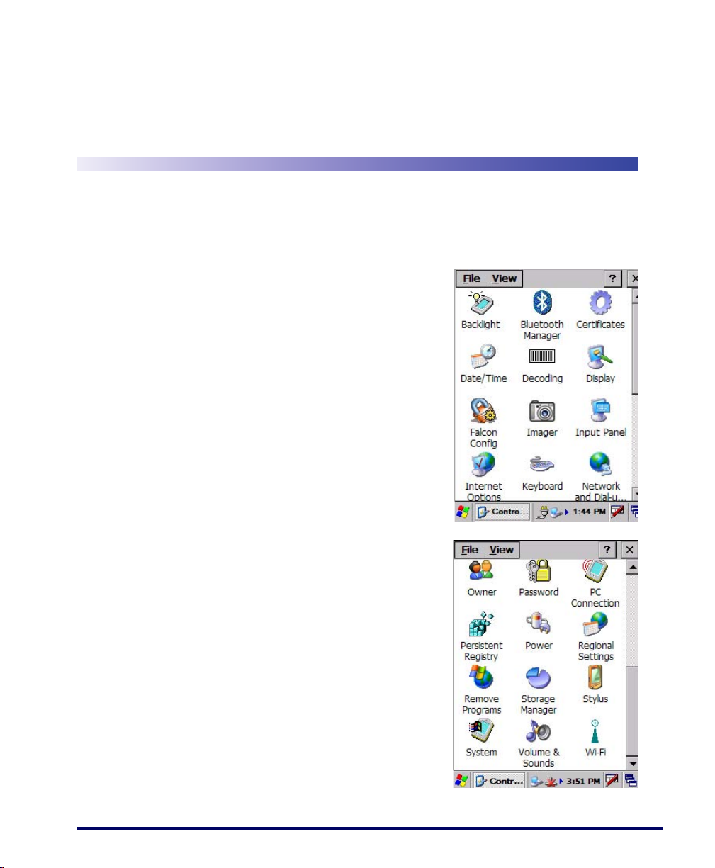
Control Panels
Chapter 2
Configuring the Falcon
This section contains the following topics
on configuring your Falcon. Most control
panels are accessed by selecting/tapping
Start > Settings > Control Panel.
• "Backlight" on page 2-2
• "Bluetooth Manager" on page 2-4
• "Certificates" on page 2-8
• "Date and Time" on page 2-8
•"Decoding" on page2-9
• "Display Configuration" on
page 2-15
• "Falcon Config" on page 2-16
• "Imager" on page 2-16
• "Input Panel Properties" on
page 2-21
• "Internet Options" on page 2-22
• "Keyboard Configuration" on
page 2-25
• "Network and Dialup" on page 2-27
•"Owner" on page2-28
• "Password" on page 2-28
• "PC Connection" on page 2-29
• "Persistent Registry" on page 2-29
• "Power Configuration" on
page 2-30
Product Reference Guide 2-1
Page 18

Configuring the Falcon
Backlight
Increasing backlight brightness can cause the battery pack to discharge at a faster
rate. The battery discharge rate decreases with a decrease in backlight usage.
To c h an g e t h e Backlight settings, complete the following steps:
• "Regional Settings" on page 2-31
• "Remove Programs" on page 2-32
• "Storage Properties" on page 2-32
• "Stylus Calibration" on page 2-33
• "System Properties" on page 2-35
• "Volume and Sounds" on page 2-38
•"Wi-FI" on page2-39
1. Select
Start > Settings > Control Panel > Backlight to open the Backlight
control panel. Some Falcon keypads also provide keyboard shortcuts
to launch the
• On the 26-key model press:
• On the 48-key model press:
• On the 52-key model press:
2. On the
Backlight control panel:
<Fn>+<Backlight> ().
<Fn>+<Backlight> ().
<Fn>+< . >.
Brightness tab (refer to Figure 2-1), select one of the five (5)
radio buttons to adjust the brightness to the desired setting by tapping
it with the stylus. You can also use the
<UP> and <DOWN> arrow keys
to adjust this setting.
3. Auto Power-Save dims (rather than turning off) the backlight after 15
seconds of inactivity. This features does not change the behavior of
the Auto-Off Settings. (Refer to "Power Configuration" on
page 2-30).
2-2
Falcon® 4400 Series with Windows® CE
Page 19
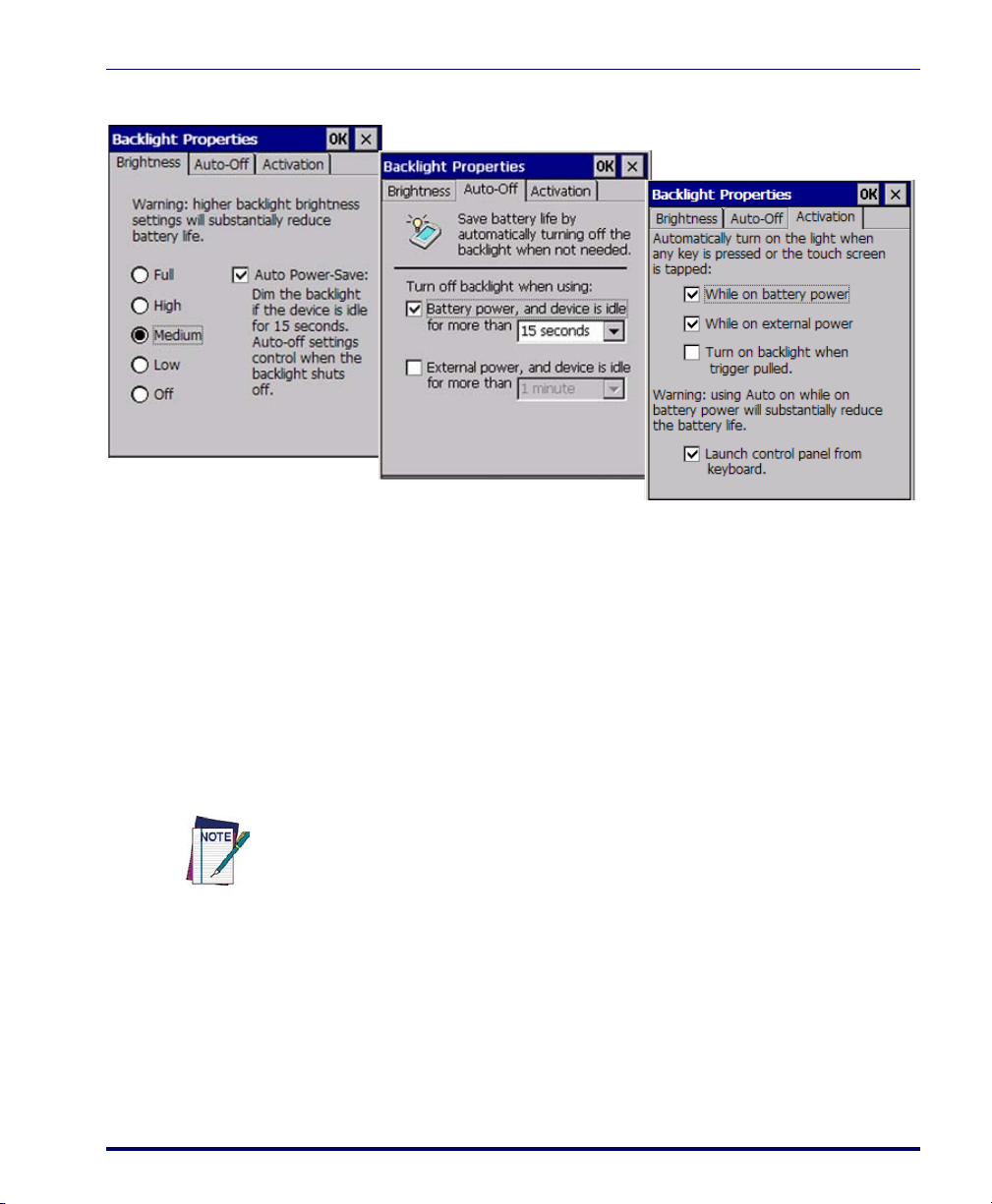
Figure 2-1. Backlight Control Panel & Brightness
4. On the Auto-Off tab, enable the desired option checkbox and select the
desired options from the pull-down lists (refer to Figure 2-1).
5. On the
Activation tab, just tap the checkbox(es) to enable or disable
them (refer to Figure 2-1):
• Set the backlight to turn on automatically when any key is pressed
or the touchscreen is tapped, either while on battery or external
power.
• Turn on the backlight when the trigger is pulled.
• Deselect Launch Control Panel from the Keyboard to turn off the
ability to open the
Backlight control panel with a key sequence.
Backlight
Using Auto-on while running from battery power will cause the battery pack to
discharge at a faster rate. The battery discharge rate decreases with a decrease in
backlight usage.
6. To exit and save your modifications, tap
<Enter> on the keypad.
press
Product Reference Guide 2-3
OK on the command bar, or
Page 20
Configuring the Falcon
Bluetooth Manager
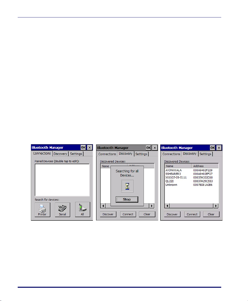
Search for device
1. Select Start > Settings > Control Panel > Bluetooth Manager to open the
Bluetooth control panel.
2. Search for the type of Device(s) you want to connect to by tapping
Printer, Serial, or All. The Falcon will search for Bluetooth Devices
within range.
3. If you attempt to set up a connection when the Bluetooth Radio is
disabled, you will receive a message reminding you that the radio is
turned off, and asking you if you want to turn it on. Tap
need to enable the Bluetooth Radio.
Once searching is complete, Bluetooth Device Profiles will be displayed in the
Discovery tab. You can set up a connection to a device on the list, or clear it
from the list by tapping the
Figure 2-2. Searching for a Bluetooth Device
Yes if you
Clear button.
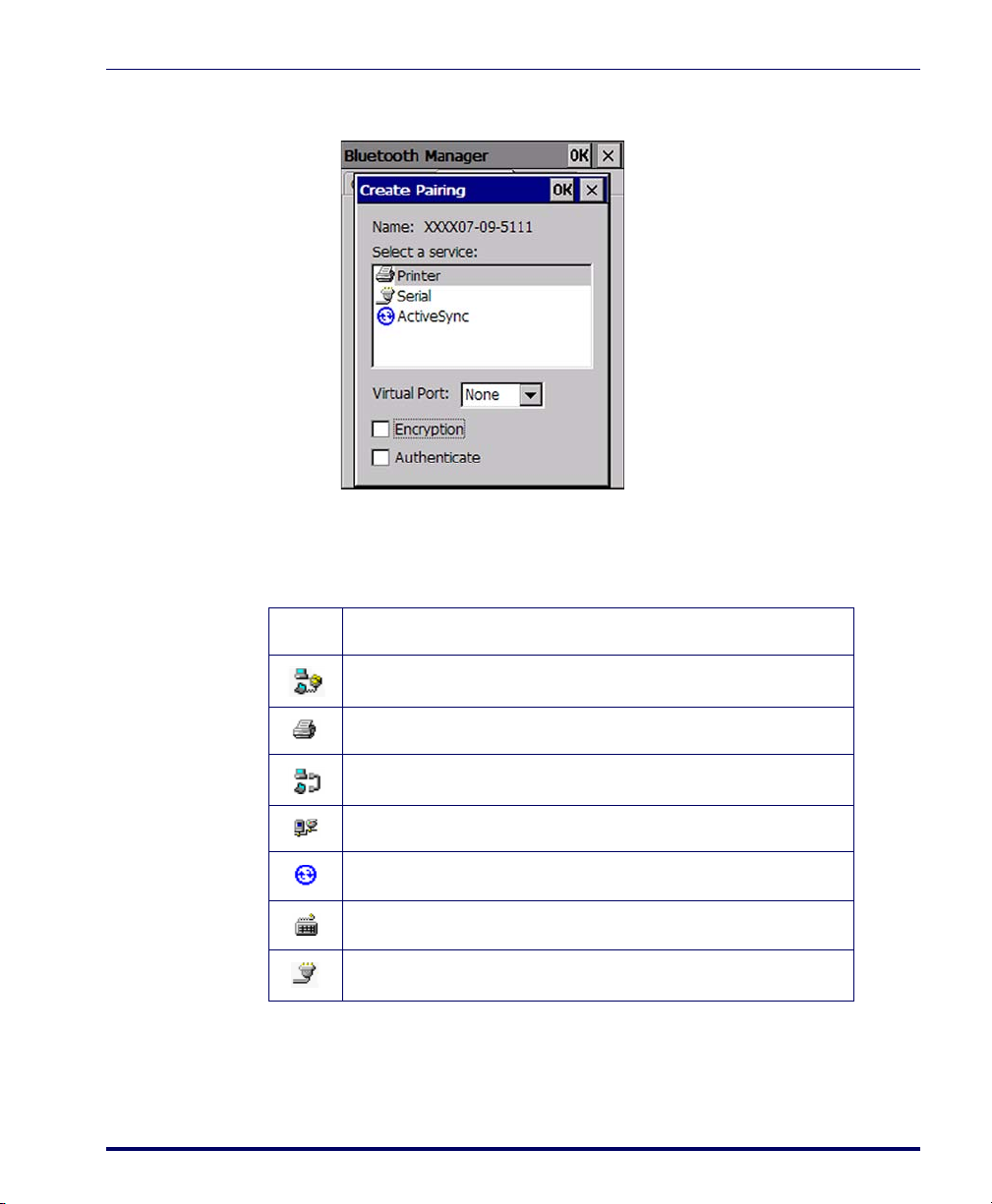
Connect to a Bluetooth Device
1. From the list of available devices, double tap the one you want to activate, or select and then tap
2-4
Connect.
Falcon® 4400 Series with Windows® CE
Page 21
Bluetooth Manager
2. The resulting dialog will display services that are available on the
device.
Select the service you want to connect to. The following table shows the icons
that display for different types of service.
Table 2-1. Bluetooth Device Icons
Icon Service
Dialup Networking
Printer
File Transfer Protocol (FTP) Object Exchange (OBEX)
Object Push (OPP) Object Exchange (OBEX)
ActiveSync
Human Interface Device (HID) - Keyboard
Serial
Virtual Port
allows you to specify the incoming port, which is used to communicate serially with an incoming device just as if it were a physical COM port.
This option is available only if you have selected a Printer or Serial service.
Product Reference Guide 2-5
Page 22
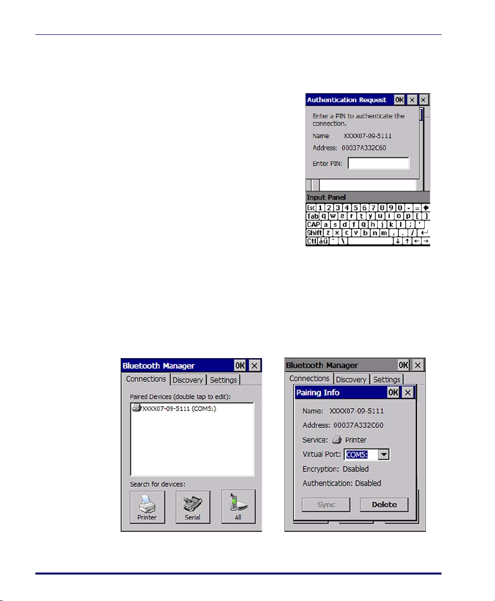
Configuring the Falcon
You can also select Encrypt or Authenticate from the Bluetooth control panel to
apply or modify those settings.
1. To require Authentication, tap the
checkbox, then tap
OK.
2. The Authentication Request dia-
log will then open, requesting that
you enter a PIN. Use the Input
Panel to type in the PIN.
3. Tap
OK to complete.
The dialog will also appear when an
Authentication request is received from
another device.
Viewing or Deleting Paired Devices
Once you have set up a Pairing, you can view the settings by double-tapping
its name from the Connections tab. Tap the arrow to change the Virtual Port,
or Delete to remove the device pairing. Tap Sync to initiate a Sync (available
only if the service is an ActiveSync connection).
2-6
Figure 2-3. Pairing Info
Falcon® 4400 Series with Windows® CE
Page 23
Bluetooth Manager
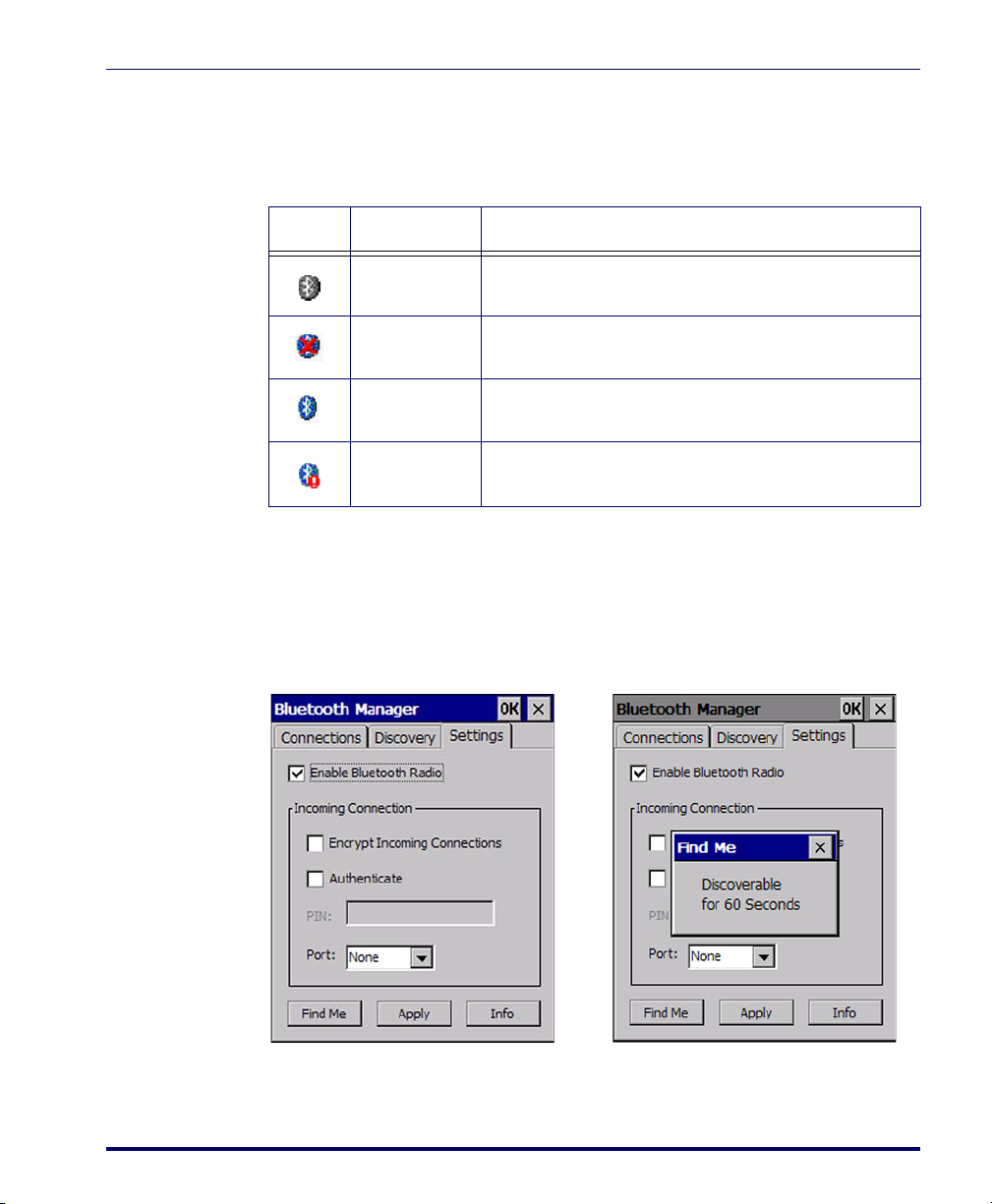
The icons displayed in the taskbar at the bottom of your Falcon’s screen will
show you the state of the Bluetooth connection, as shown in Ta bl e 2 - 2.
Table 2-2. Bluetooth taskbar icons
Icon Name Description
Disabled Icon Indicates that the Bluetooth has been disabled.
Settings
Unpaired Icon
Paired Icon
Discoverable
Indicates that the Bluetooth radio is on but the device is
currently not paired to another.
Indicates that the Bluetooth radio is on and the device is
paired with at least one other device.
Indicates that the device is discoverable by other Bluetooth
devices.
The Settings tab allows you to enable or disable the Bluetooth radio and specify settings for Incoming Connections.
Ta pp in g
Find Me will make the Falcon available to other Bluetooth devices for
60 seconds, allowing them to set up a connection.
Apply to apply the settings you have selected.
Ta p
Product Reference Guide 2-7
Page 24
Configuring the Falcon
Certificates
Certificates are used by some applications for establishing trust and to secure
communications. See the Microsoft Windows CE help on your Falcon unit for
further information about Certificates.
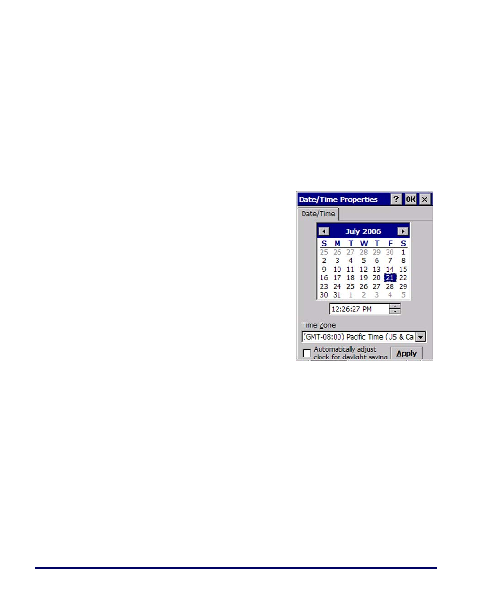
Date and Time
In this control panel, you can change the year, month, date, time, time zone,
or select automatic adjust for Daylight Savings Time. To set or change the date
and time:
1. Select
Start > Settings > Control
Panel > Date/Time
.
2. Select the month to open a pull-
down list of months or tap the
arrow buttons on either side of
the month to increase or decrease
the month.
3. To change the year, select the year
to open a numeric dial. Select the
up arrow to increase the value;
select the down arrow to decrease
the value. Or you can type a new
year value in the field.
4. To change the time, select the
hour, minute, seconds, or AM/PM and select the up arrow to increase
the value; select/tap the down arrow to decrease the value. Or you can
type a new time value in the field.
5. Select your correct time zone from the pull-down list.
6. To automatically adjust the clock for Daylight Savings Time, enable
the checkbox at the bottom of the screen.
7. Select
Apply to save your changes and make additional modifications.
• Select
OK to save your changes and exit Date/Time Properties.
• Select/tap the close button to exit without saving your changes.
2-8
Falcon® 4400 Series with Windows® CE
Page 25
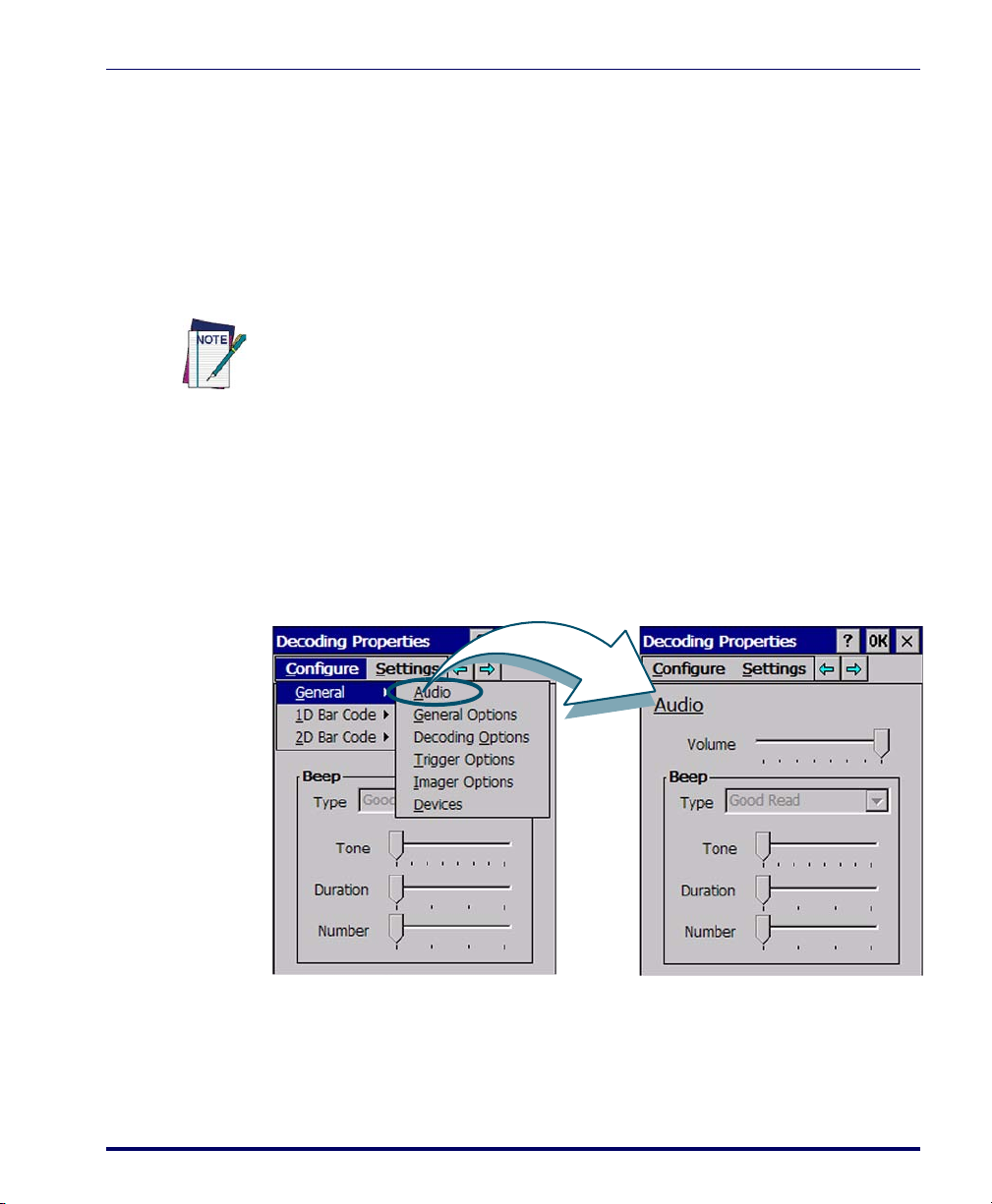
Decoding
To view other configuration options, select Configure > General from the menu
Decoding
You can configure the Falcon’s decoding options by tapping on Start > Settings
> Control Panel > Decoding
large numbers of terminals using
. Decoder configuration can also be accomplished for
FMU (Falcon Management Utility).
There are two sections in the
Decoding control panel, each containing addi-
tional pages. There are six General Configuration pages and multiple Bar
Code symbology pages.
Other decoding parameters are described in Programming Parameters, starting
on page F-1; bar code settings are provided in Programming Bar Codes, starting
on page G-1.
Configuration Control Panels
Select the desired configuration from the following options shown in Figure 2-
4, and the other
Use the pull-down menus or tap the left and right arrow keys to navigate the
different pages of the
Figure 2-4. Decoding Properties: Audio
Decoding Properties figures on the following pages.
Configure utility.
• Audio: Sets volume, tone, duration, and number of various types of
beeps.
Product Reference Guide 2-9
Page 26
Configuring the Falcon
To view other configuration options, select Configure > General from the menu
To view other configuration options, select Configure > General from the menu
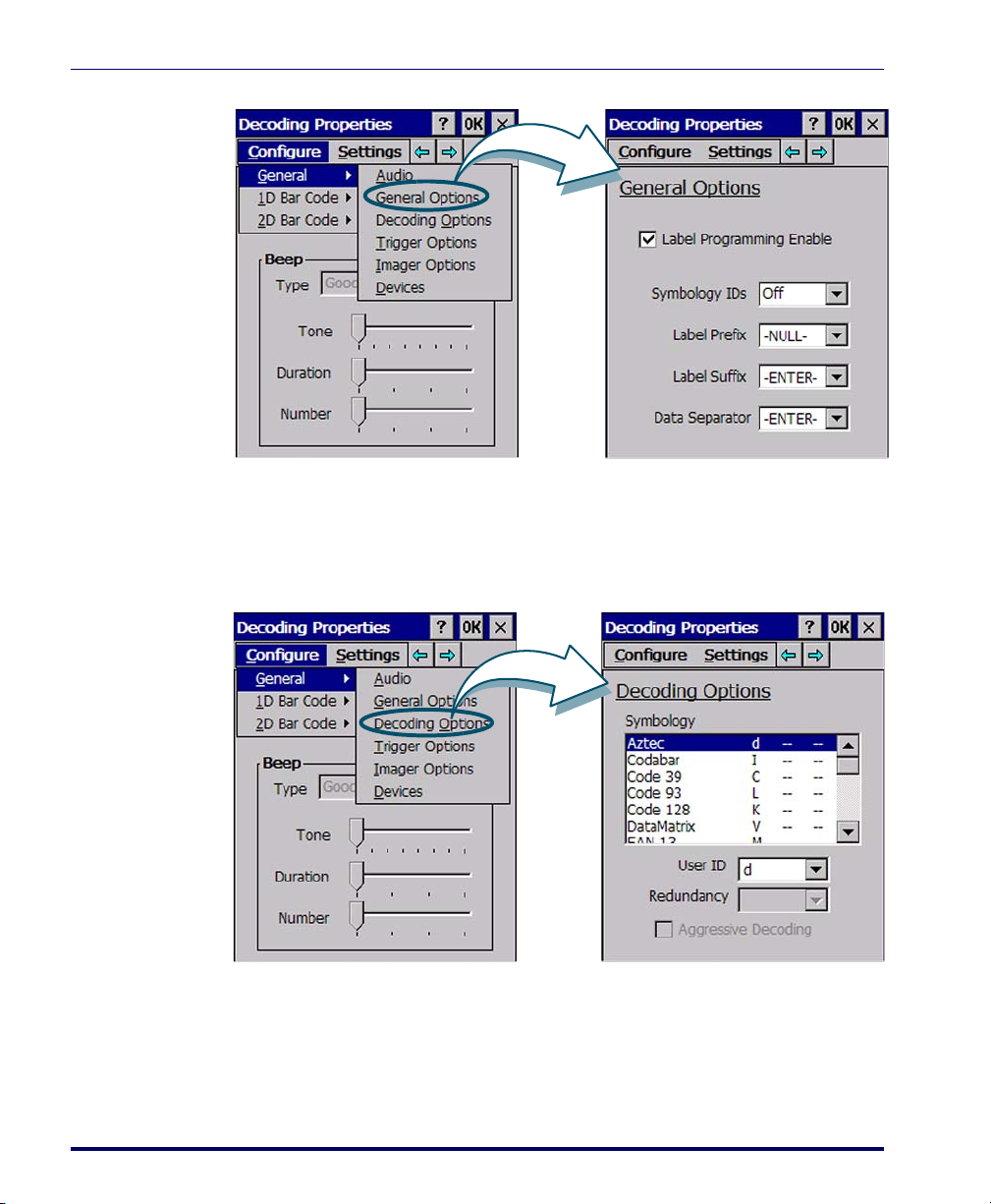
Figure 2-5. Decoding Properties: General Options
Figure 2-6. Decoding Properties: Decoding Options
• General Options: Select from Label Programming Enable, Symbology
IDs, Label Prefix, Label Suffix, and Data Separator options.
• Decoding Options: Set the User ID character associated with a symbology,
the
Redundancy and select Aggressive Decoding when available.
2-10
Falcon® 4400 Series with Windows® CE
Page 27
Decoding
To view other configuration options, select Configure > General from the menu
To view other configuration options, select Configure > General from the menu
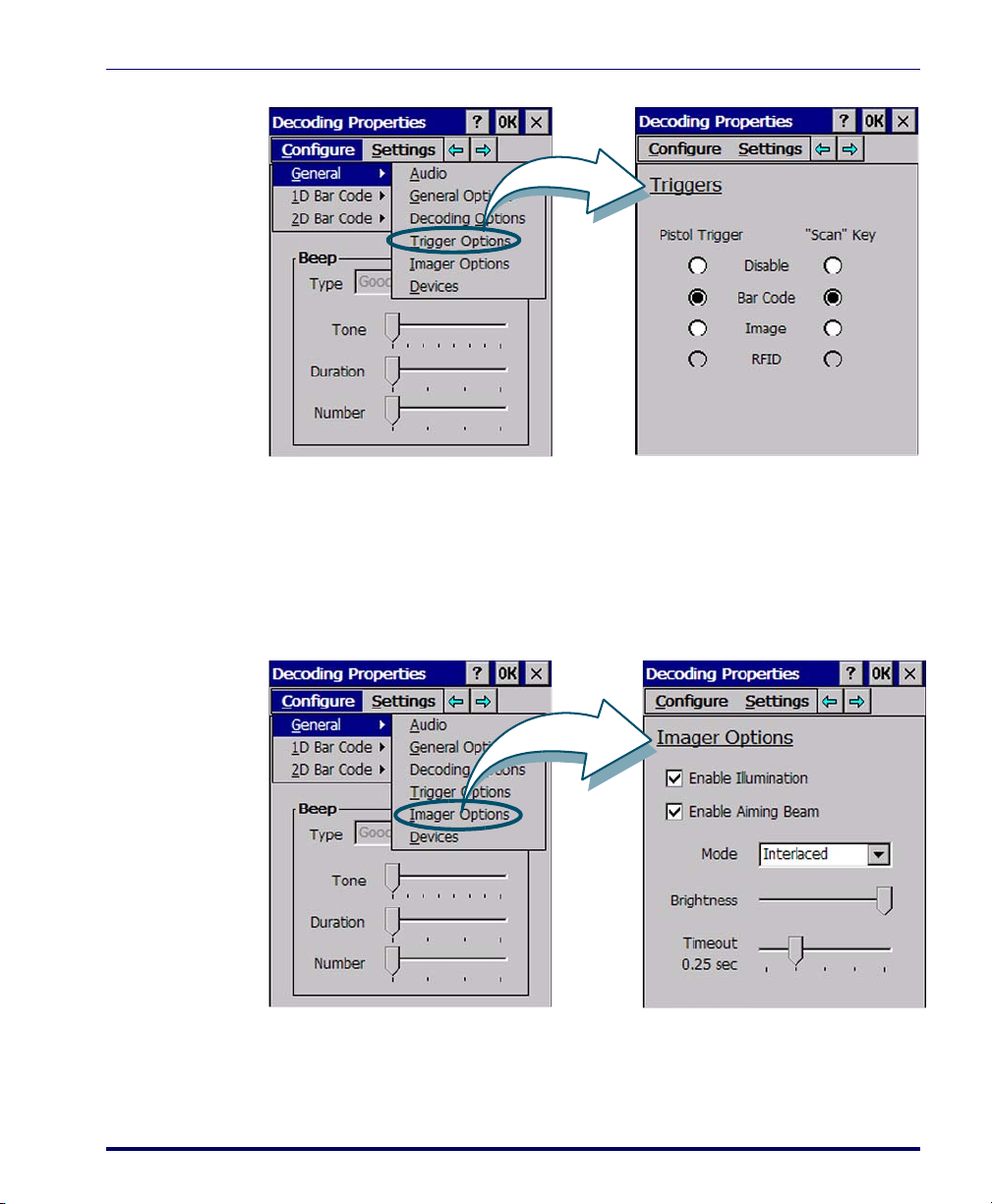
Figure 2-7. Decoding Properties: Trigger Options
• Trig g e r O p tions: Select from Pistol Trigger and Scan Key enable for Bar
code, Image, and RFID (available in future versions). Select the desired
radio buttons to define the button functions. Available items will vary
depending on the model.
Figure 2-8. Decoding Properties: Imager Options
• Imager Options: (Models with Imaging module only). Enable/Disable
Illumination and the Aiming Beam for Imaging. Mode lets you select
Product Reference Guide 2-11
Page 28
Configuring the Falcon
To view other configuration options, select Configure > General from the menu
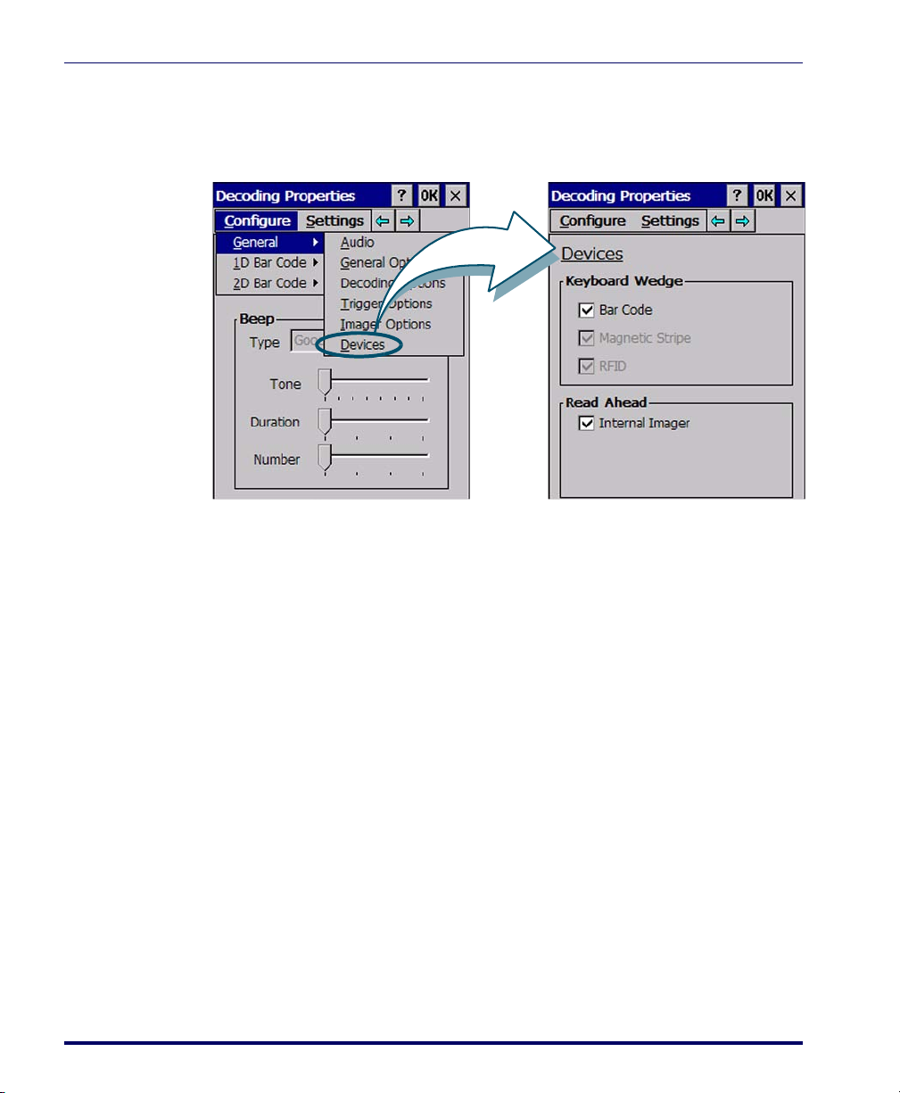
Figure 2-9. Decoding Properties: Devices
between Concurrent (the aiming beam and the illumination beam turn
on at once); and
being on). Set
Interlaced (the aimer beam and illumination alternate
Brightness and Timeout properties using the sliders.
• Devices: Enable the keyboard wedge for bar code scanner, Magnetic
Stripe Reader, RFID, and enable Read-Ahead for attached devices.
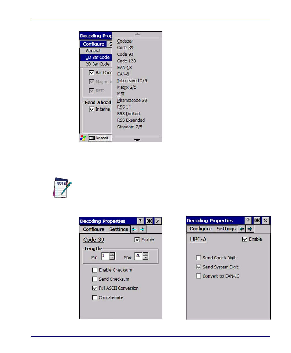
Bar Code Symbology Pages
Use the pull-down menus from Configure > 1D Bar Code or 2D Bar Code, or tap
the left and right arrow keys to navigate the different pages of the bar code
symbology pages. Each bar code symbology opens to its own page, as shown in
Figure 2-11 on page 2-13.
2-12
Falcon® 4400 Series with Windows® CE
Page 29
Decoding
Codabar Pharmacode 39
Code 39 RSS-14
Code 93 RSS-Limited
Code 128 RSS-Expanded
EAN-13 Standard 2/5
EAN-8 Trioptic
Interleaved 2/5 UPC-A
Matrix 2/5 UPC-E
MSI UPC/EAN Extensions
See
Appendix G for details on parame-
ters available for each symbology.
Figure 2-10. Available 1D Bar Code Symbologies
Refer to the sample symbology control panels in Figure 2-11 for examples of
the types of fields and options you can modify.
Decoding parameters are described in Programming Parameters, starting on
page F-1; bar code settings are provided in Programming Bar Codes, starting on
page G-1.
Figure 2-11. Common Symbologies: Code 39 and UPC-A
Product Reference Guide 2-13
Page 30
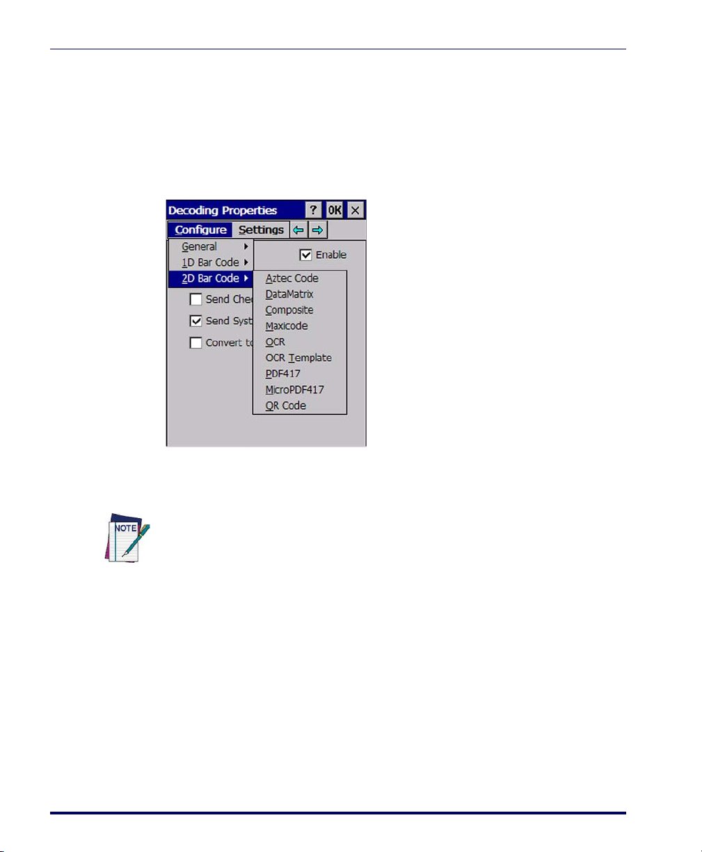
Configuring the Falcon
Aztec Code OCR
Data Matrix OCR Template
Composite
PDF417
Code 128
MicroPDF417
MaxiCode QR Code
See Appendix G for details on parameters available for each symbology.
2D Bar Code Symbologies
If you have the 2D Imager module installed, the following additional symbology options are also available:
• Code 39: Select from enable, min/max lengths, enable checksum, send
checksum, and Full ASCII conversion.
•
UPC-A: Select from Enable, Send Check Digit, and Send System Digit.
2-14
Refer to Figure 2-11 for an example of the types of fields and options you can
modify.
Other decoding parameters are described in Programming Parameters, starting
on page F-1; bar code settings are provided in Programming Bar Codes, starting
on page G-1.
Falcon® 4400 Series with Windows® CE
Page 31

Settings
Select from the Settings menu to restore
previous configurations and/or other
available default settings. Choose from:
•Factory Defaults
• Minimum Settings
• Maximum Settings
• Save (New Settings)
• Reverts to Saved Settings
The settings are saved when you select/
tap
OK.
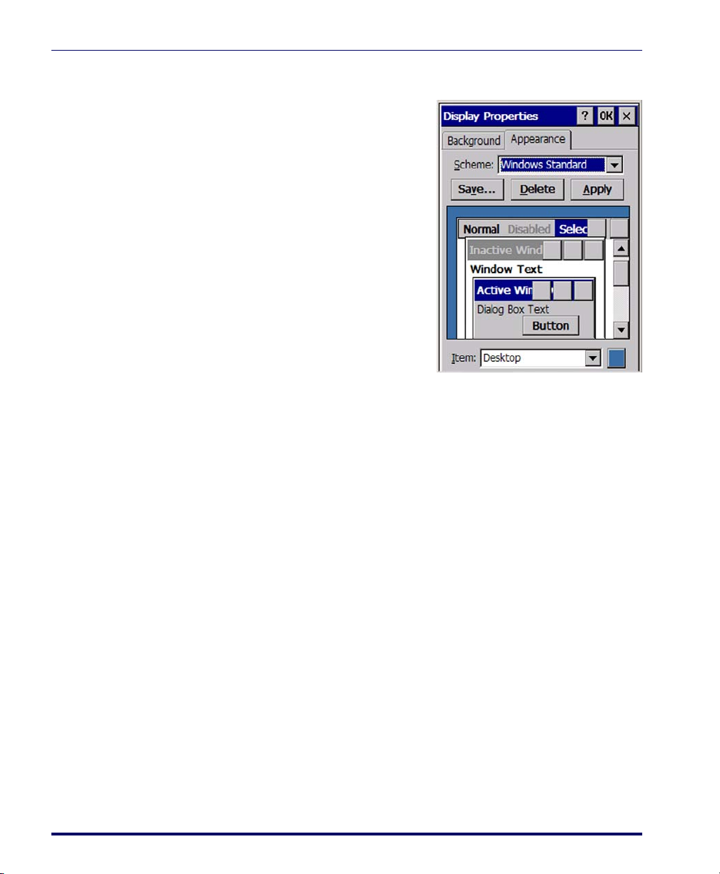
Display Configuration
To change the default Background or Appearance (Windows Color Scheme),
select
Start > Settings > Control Panel > Display.
Display Configuration
Background
To c h an g e t h e Background image:
1. Select
2. Place a new image in the Win-
3. The current file is located in the
4. Select the new file name by
Product Reference Guide 2-15
Start > Settings > Control
Panel > Display
dows directory. This file must
be exactly 240 pixels wide by
320 pixels high.
Windows directory with the
Datalogic logo file named
DeskLogo.bmp.
using
Browse.
.
Page 32
Configuring the Falcon
Appearance
To change the default Windows color
scheme:
1. Tap the
Appearance tab.
2. Tap the
3. Tap
Falcon Config
Ta p Start > Settings > Control Panel > Falcon Config to access configuration utilities such as the Falcon Management Utility (FMU) and Falcon Desktop Utility (FDU) settings. See Falcon® Desktop Utility for Windows® CE, starting
on page B-1, for complete information on FDU.
Falcon Management Utility (FMU)
The Falcon Management Utility (FMU) is the easiest method to use to configure multiple Falcons, especially if you have an enterprise-wide deployment. A
copy of FMU is shipped with all Falcon Windows CE units. For complete
information on FMU, refer to the FMU User’s Guide on the product CD
included with your Falcon.
Scheme pull-down list
and select a new Windows color
scheme if desired.
OK on the control bar, or
<Enter> on the keypad.
press
Imager
Imaging Overview
If your Falcon has the Imager module installed, you will see the Imaging Control Panel on your screen. Select
See "Sample Imager Settings" on page 2-20 to view sample settings for different conditions.
2-16
Start > Settings > Control Panel > Imager.
Falcon® 4400 Series with Windows® CE
Page 33
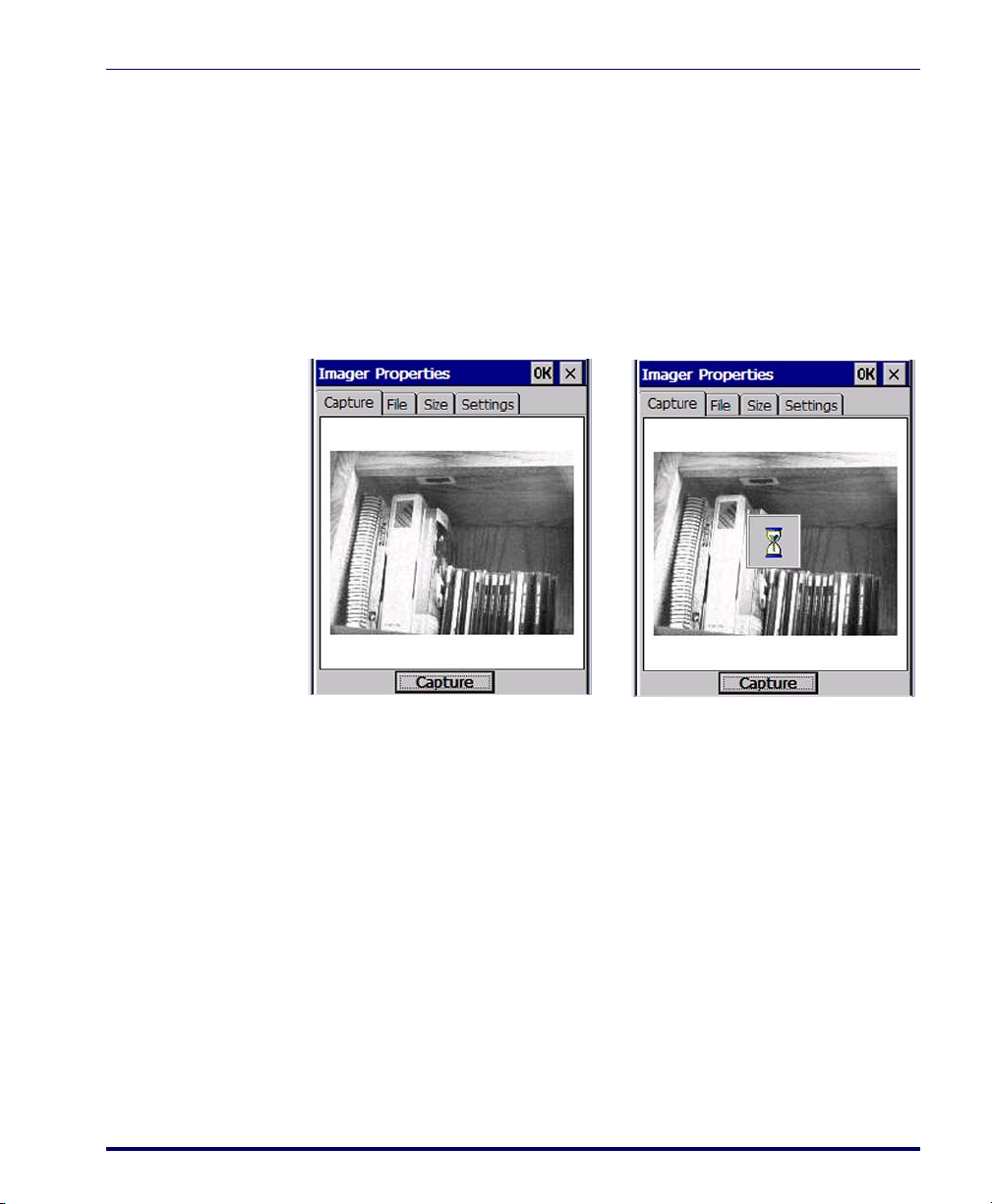
Image Capture
B
A
The Capture page allows you to preview and capture an image with the Falcon.
To capture an image:
1. Aim the Falcon toward the image you want to capture. The screen
2. Tap
Figure 2-12. Image Capture Settings
Imager
will display a preview of the image, making use of the current settings
(to change the settings, see "Image Settings" on page 2-20).
Capture (refer to Figure 2-12A) or press and hold the trigger.
3. An hourglass will appear, indicating the image capture process has
begun (see Figure 2-12B). Continue to hold the Falcon steady until
you hear the capture sound, signifying that the image capture is complete.
Product Reference Guide 2-17
Page 34
Configuring the Falcon
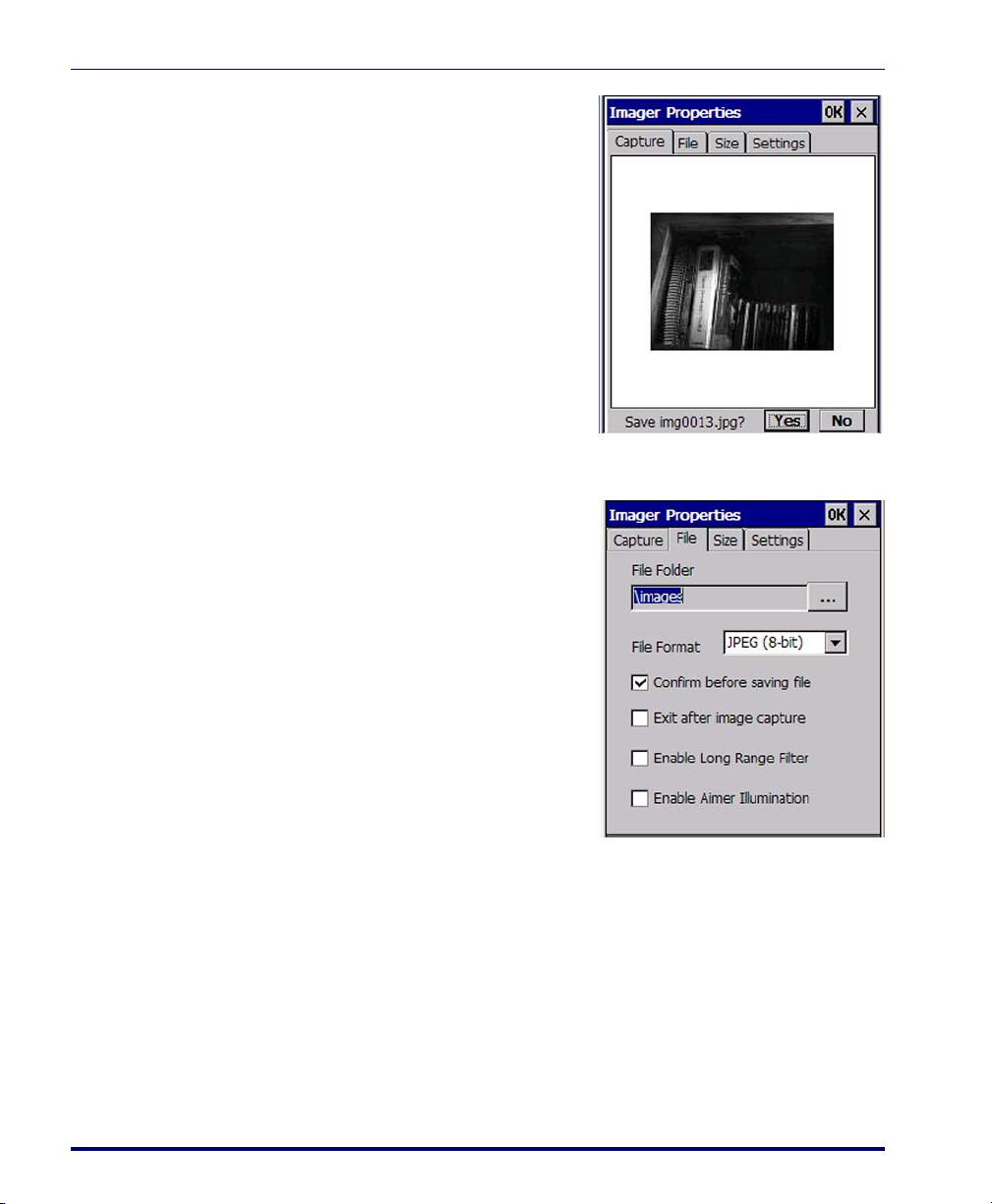
Image File
4. A File Save message showing the
image file name will appear,
unless that option has been previously deselected in the
File set-
tings (in that case, the file will
automatically save without
prompting). See "Image File" on
page 2-18, to change settings.
5. Tap
Yes to save the image, or No
to discard it.
1. Specify where you want images to
be saved in the
File Folder field. If
you do not select a folder, images
will be saved to the default folder
“\Images.” Use
… (browse) to
browse to a different folder.
2. Use
File Format to select the image
format you want. You can choose
between the following graphics
formats:
• TIFF (1-bit monochrome)
• TIFF (8-bit grayscale)
• JPEG (8-bit grayscale)
• BMP (1-bit monochrome)
• BMP (8-bit grayscale)
3. Check
Confirm before Saving File to automatically get a File Save mes-
sage when saving images (see Figure 2-12B). If unchecked, the file will
automatically save to the specified file folder (at the root of the Falcon’s drive) without prompting.
2-18
4. Check
Exit after Image Capture to cause the Imaging Control Panel to
close automatically after saving the image to a file.
Falcon® 4400 Series with Windows® CE
Page 35

Image Size
5. Enable Long Range Filter enhances pictures taken from very long dis-
tances (greater than 10 feet or 3 meters).
6.
Enable Aimer Illumination turns on the aimer LEDs to provide more
light for an image capture.
On the Size tab, modify the image property settings as desired. Both keyboard and
stylus input are supported.
1. Use the
Width and Height controls
to adjust the image.
• Width can be as much as 640
pixels.
• Height can be as much as 480
pixels.
Reducing the height and width
results in cropping of the image to
the center.
Imager
2. Use
Scale to scale the image. Scal-
ing changes the x,y dimensions of the image. For example, scaling a
640 x 480 image to 50% results in an image size of 320 x 240. See
"Imaging Controls" on page F-32, for further information.
Reducing the scale of an image results in reduced image size, which decreases
the time needed to capture an image.
3.
Rotate allows you to change the orientation of the image, in 90° incre-
ments.
Product Reference Guide 2-19
Page 36
Configuring the Falcon
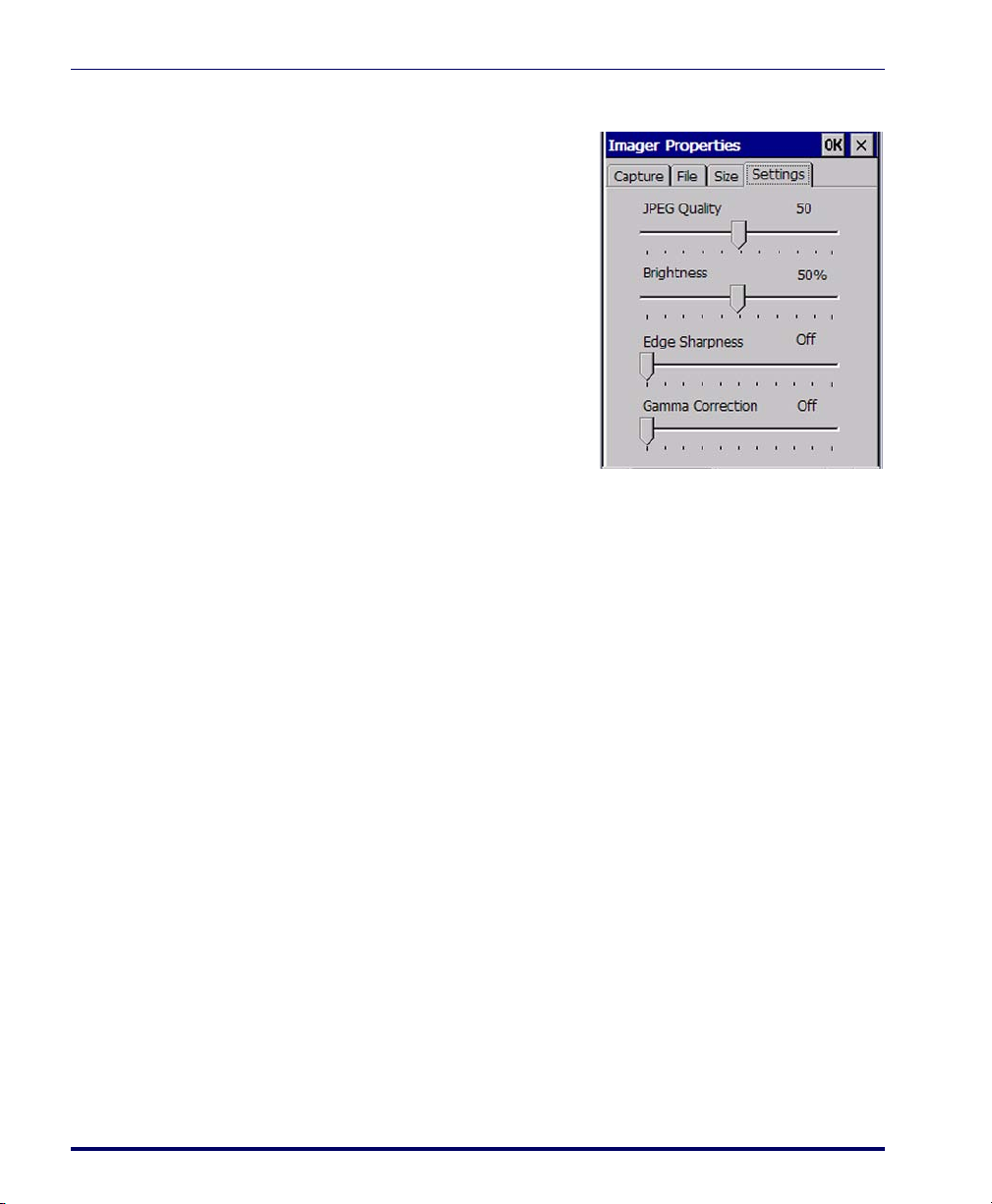
Image Settings
1. JPEG Quality sets the desired qual-
2.
3.
4.
ity when the JPEG image format
is selected. Selecting a higher
quality results in a higher quality
image, but a larger file.
Brightness allows you to set the
brightness level the imager will
use when taking images.
Edge Sharpness specifies how
much the imager will attempt to
sharpen edges in images it takes.
Selecting the highest position on
the slider gives the sharpest edges,
but also increases noise in the
image.
Gamma Correction measures the brightness of midtone values pro-
duced by the image. You can brighten or darken an image using
gamma correction. A higher gamma correction yields an overall
brighter image. The lower the setting, the darker the image. Move the
slider to change the amount of correction the imager applies when
taking images.
Sample Imager Settings
To obtain the best possible results, you can modify the settings to suit specific
conditions or purposes. Ta b le 2 - 3 shows samples of recommended settings for
common usages. These settings are suggested only, you will need to take into
account your particular environment and conditions to determine optimal settings for your specific situation.
2-20
Falcon® 4400 Series with Windows® CE
Page 37
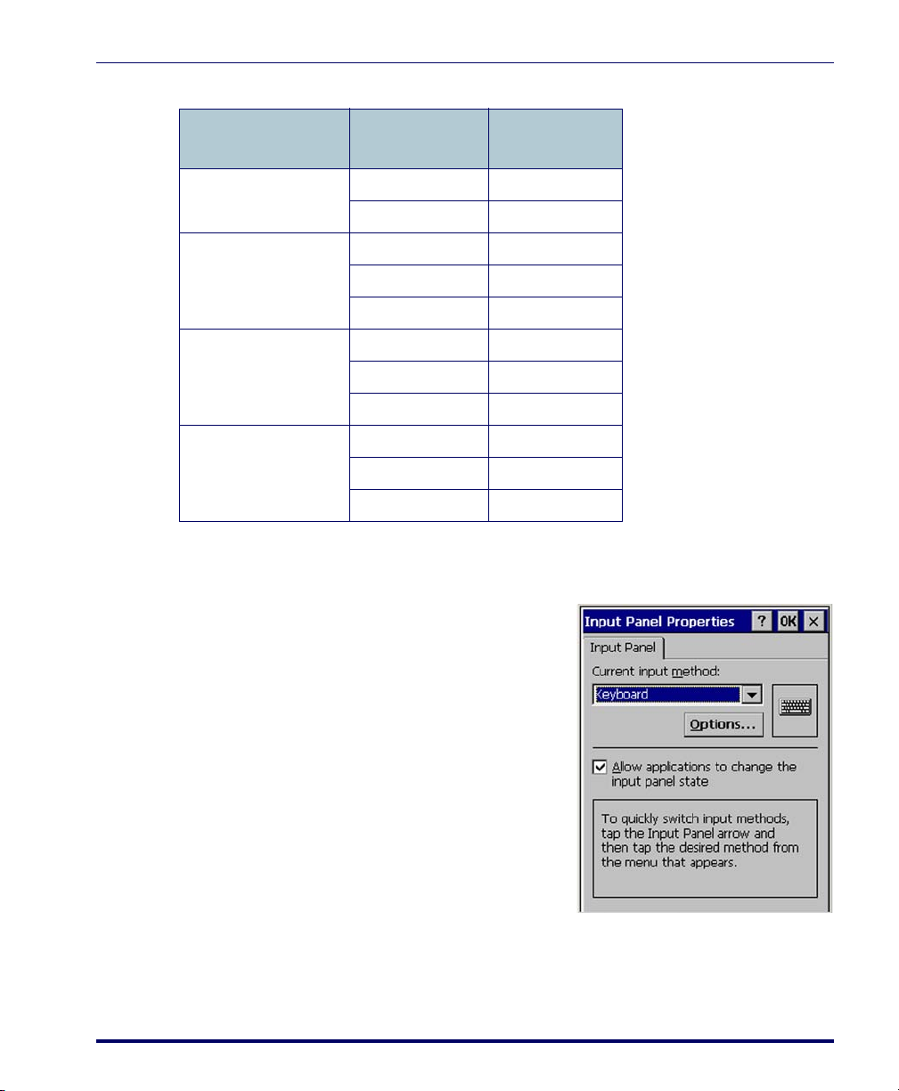
Table 2-3. Sample Imager Settings
Input Panel Properties
Condition Item
Distance >10 ft (3 m)
Low light
Printed Text
Signature
Long Range filter On
Illumination Off
Illumination On
Brightness 100%
Gamma Correction 20
Illumination On
Sharpness 100%
File format 8-bit
Illumination On
Sharpness 100%
File format 1-bit
Input Panel Properties
To c h an g e t h e Soft Input Panel settings:
1. Select
Start > Settings > Control
Panel > Input Panel
.
Recommended
Setting
2. Change the desired settings.
3. To change the
Options
, tap Options.
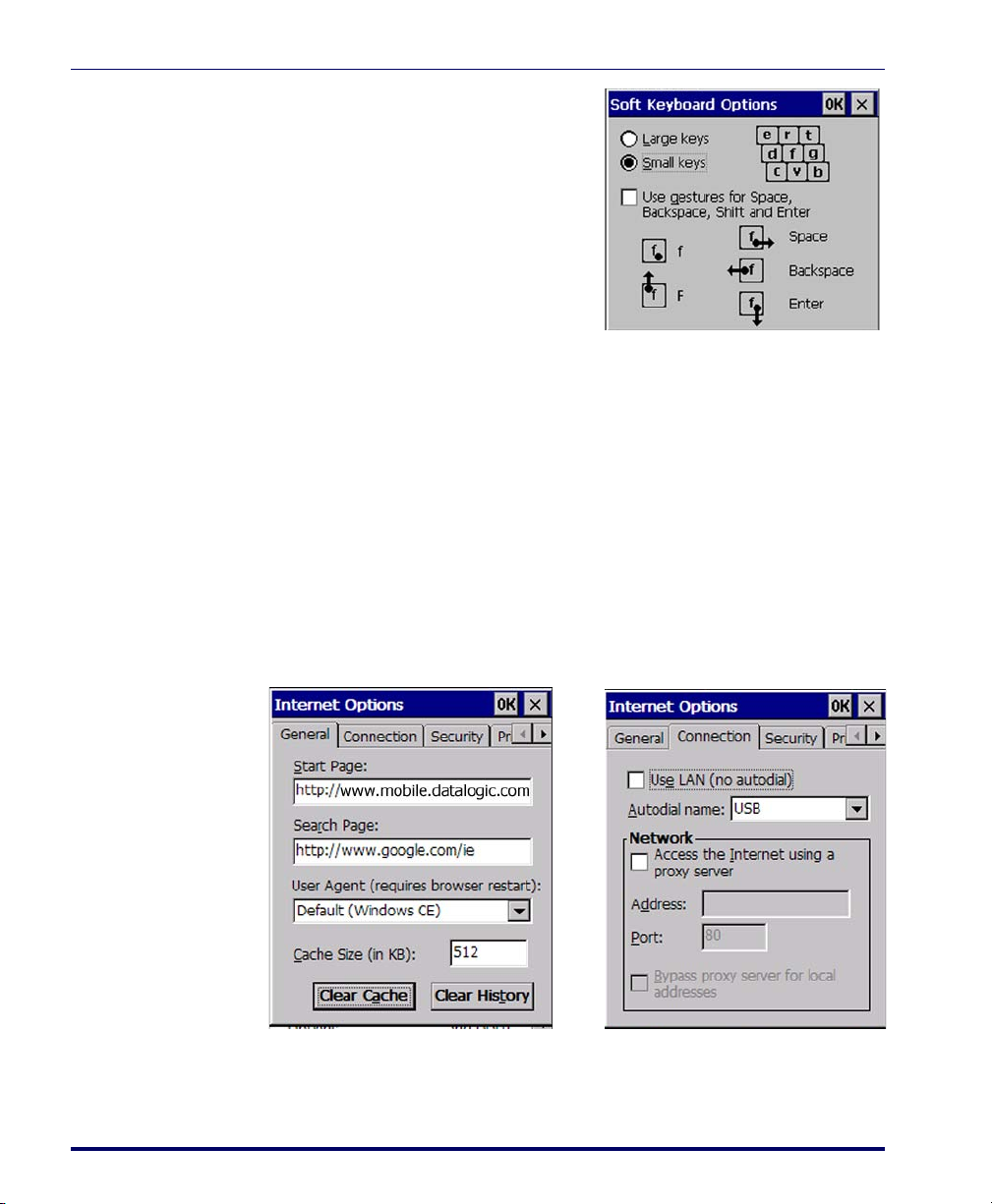
Soft Keyboard
4. Change the soft keyboard
options as desired, selecting
from:
• Large or small keys.
• Using gestures for space,
backspace, shift, and enter.
Product Reference Guide 2-21
Page 38
Configuring the Falcon
B
A
5. To exit the Soft Keyboard
Options
bar, or press
pad.
6. To exit
OK on the control bar, or press
<Enter> on the keypad.
Internet Options
To c h an g e t h e Internet default settings:
1. Select
, tap OK on the control
<Enter> on the key-
Input Panel settings, tap
Start > Settings > Control Panel > Internet Settings.
2. On the
General tab (refer to Figure 2-13A), type in the URL of the
desired start page and the desired search engine. You can also select a
User Agent, change the
Cache Size, clear the Cache, and clear the His-
tory.
3. On the
Connection tab (refer to Figure 2-13B) modify the network
access settings as desired.
Figure 2-13. Internet Settings
2-22
Falcon® 4400 Series with Windows® CE
Page 39

Internet Options
B
A
4. On the Security tab (refer to Figure 2-14A) add sites or modify the
security settings for Internet, Local intranet, Trusted Sites, and
Restricted Sites.
Figure 2-14. Internet Settings
5. The Privacy tab (refer to Figure 2-15) allows you to modify the set-
tings by tapping the radio buttons. You can Accept, Block or receive a
Prompt for First-party and Third-party Cookies. You can also Enable/
disable session cookies by selecting the check box.
Figure 2-15. Internet Privacy Settings
Product Reference Guide 2-23
Page 40
Configuring the Falcon
B
A
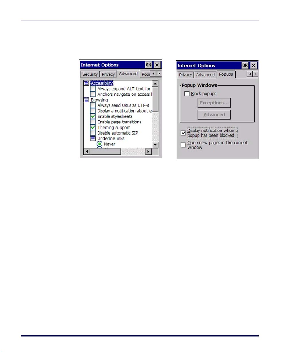
Figure 2-16. Advanced Internet and Popup Settings
6. On the Advanced tab (refer to Figure 2-16A) modify the advanced set-
tings for Accessibility, Browsing, Multimedia, and Security by tapping
the check boxes.
7. The Popups tab provides options for blocking popups, to display notification when popups have been blocked, and to open new pages in
the current window.
2-24
8. To exit
the keypad.
Internet Settings, tap OK on the control bar or press <Enter> on
Falcon® 4400 Series with Windows® CE
Page 41

Keyboard Configuration
The keyboard control panel will appear different, depending upon which keypad your Falcon has.
26-Key Keypad
1. Select Start > Settings > Control Panel
> Keyboard Options
Keyboard control panel.
2. Adjust the slider for
out
to match your personal prefer-
ences.
3. Use the box provided to test the
time-out delay.
4. Tap
OK to exit the Keyboard Options
control panel.
to open the
Keyboard Configuration
Multi-Tap Time-
48, 52 and 52-Key NU Keypads
The control panels for the 48, 52 and 52-key NU keypads have some additional options and an additional tab for key mapping.
1. Select
2. On the
Product Reference Guide 2-25
Start > Settings > Control Panel > Keyboard to open the Keyboard
control panel for your keypad.
Options tab, adjust the slider for Initial Delay. This configures
the time to hold down a key before it repeats.
Page 42

Configuring the Falcon
Figure 2-17. 48-Key or 52-Key Keypad Control Panels
3. You can also adjust the slider for Repeat Rate. This configures how fast
the keys repeat.
4. Use the box provided to test the selected repeat rate setting.
5. On the
or change to the
Load Map tab, you can select a keyboard key-map by browsing,
Default Map.
6. Use the box provided to test the current keyboard mapping.
2-26
7. Tap
panel.
OK to save your changes and exit the Keyboard Options control
Falcon® 4400 Series with Windows® CE
Page 43

Network and Dialup
To change the Network and Dialup connection settings, complete these
steps:
1. Select Start > Settings > Network and Dialup Connections.
Figure 2-18. Changing Network & Dialup Settings.
Network and Dialup
2. Double-tap the connection to view or change the settings. The
SDCCF10G1 item shown in the example above can vary, depending
on the radio installed and the number of connections.
3. Complete the two tabs as shown in Figure 2-18:
• IP Address: Select DHCP or set static IP settings.
• Name Servers: If using static IP, set DNS and WINS servers.
Product Reference Guide 2-27
Page 44

Configuring the Falcon
Owner
To c h an g e t h e Owner default settings:
1. Select
Start > Settings > Control
Panel > Owner Properties
Input Panel opens to facilitate
. The
entering data.
2. Enter data using the input
panel or the keypad on the
PDA.
3. To exit the
control panel, tap
control bar, or press
Owner Properties
OK on the
<Enter> on
the keypad.
Password
For more information on using the
work ID
tab, refer to "Setting Up the
Network ID" on page 4-8.
To c h an g e t h e Password default settings:
1. Select
Start > Settings > Control
Panel > Password Properties
2. Enter the desired password
twice as indicated in the two
fields.
3. Select to enable password protection at power-on and/or
enabling password protection
for the screen-saver.
4. To exit the
panel, tap
bar, or press
Password control
OK on the control
<Enter> on the
keypad.
Net-
.
2-28
Falcon® 4400 Series with Windows® CE
Page 45

PC Connection
The PC Connection control panel determines how ActiveSync works with the
PDA. To modify the default settings:
PC Connection
1. Select
Start > Settings > Control
Panel > PC Connection
2. Select the first checkbox to
enable direct connections to
the desktop computer.
3. Tap
Change Connection to
modify the connection method
from USB or Serial.
4. To exit the
dialog, tap
bar, or press
keypad.
5. To exit the
erties
control panel, tap OK on
the control bar, or press
<Enter> on the keypad.
Persistent Registry
Persistent Registry saves the RAM-based
registry to persistent storage.
.
Change Connection
OK on the control
<Enter> on the
PC Connection Prop-
1. Tap
2. Tap
Persist to persist the registry.
Persist registry settings to
automatically persist the settings
at the time specified in the dropdown box
3. Tap
Clear to delete all persistent
registry files from the Flash FX
disk.
Product Reference Guide 2-29
Page 46

Configuring the Falcon
Automatically persisting the registry at frequent intervals may slow system performance.
Power Configuration
To a d ju s t p o we r m a n a g e ment settings, select Start > Settings > Control Panel >
Power
. Use this control panel to check the charge on the battery or to change the
Power settings.
Battery Tab
The Battery tab provides power indicators for External power, Main battery, and
Backup battery as shown in Figure 2-19 on page 2-30. To save your settings, tap
OK on the command bar, or press <Enter> on the keypad.
Power Off Tab
The Power Off tab allows you to determine the idle duration and suspend mode
initiation to save battery power
your settings, tap
OK on the command bar, or press <Enter> on the keypad.
as shown in Figure 2-19 on page 2-30. To save
2-30
Figure 2-19. Battery and Power Tabs
Falcon® 4400 Series with Windows® CE
Page 47

Regional Settings
To c h an g e t h e Regional Settings defaults, select Start > Settings > Control Panel >
Regional Settings
1. Select your locale from the dropdown box. See Figure 2-20 on page
2-31.
Regional Settings
.
2. Review the
Customize to change the appearance of
Date.
Figure 2-20. Region and Custom Settings
Appearance Samples in the bottom half of the screen. Click
Number, Currency, Time, and
3. The options on the Language tab are disabled because the Falcon will
display only in English.
4. The Input Panel will open to facilitate data input.
Product Reference Guide 2-31
Page 48

Configuring the Falcon
Figure 2-21. Language and Input Tabs
5. To exit Regional Settings, tap OK on the control bar, or press <Enter>
on the keypad.
Remove Programs
See "Removing Programs" on page 3-7.
Storage Properties
To c h an g e t h e Storage Properties control panel default settings:
2-32
Falcon® 4400 Series with Windows® CE
Page 49
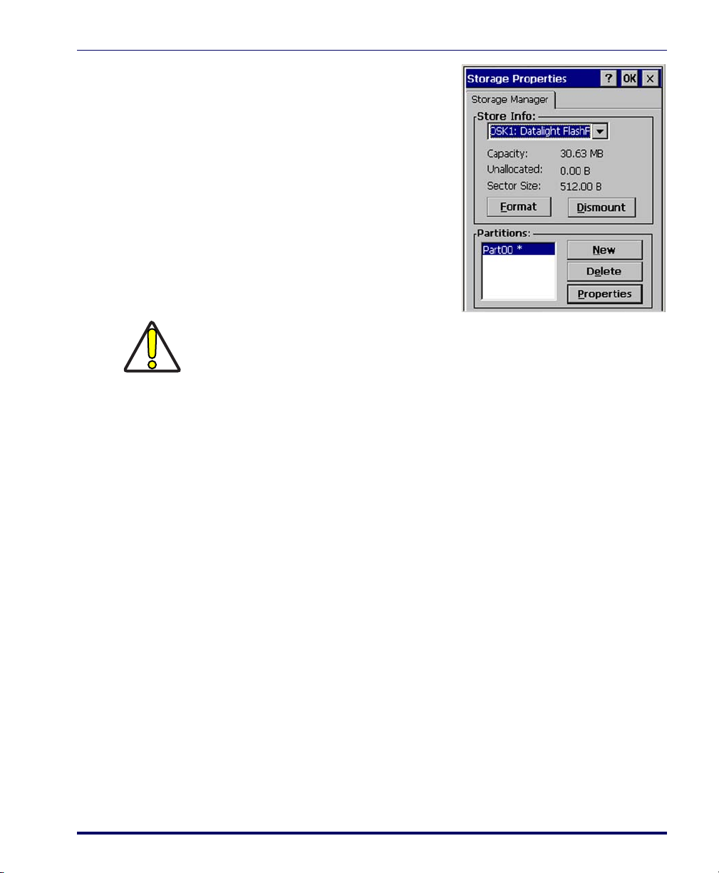
1. Select Start > Settings > Control
Panel > Storage Properties
2. From the
list, select the desired storage
device.
3. You can also format, dismount,
and create partitions on storage
devices using this control panel.
4. To save and exit the
Properties
on the control bar, or press
<Enter> on the keypad.
Dismounting or formatting the FlashFX drive will erase all files and program stored in
the drive.
CAUTION
Stylus Calibration
Stylus Calibration
.
Store Info pull-down
Storage
control panel, tap OK
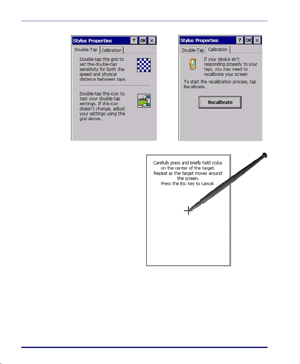
You might need to recalibrate the touch screen (i.e. when you attempt to select
one item with the stylus, another item is erroneously selected).
To recalibrate the touch screen, complete the following steps:
1. Select
2. Adjust
3. Select the
Product Reference Guide 2-33
Start menu > Settings > Control Panel > Stylus to open the Stylus
Properties
dialog as shown in Figure 2-22 on page 2-34.
Double-Tap sensitivity if needed or desired.
Calibration tab to open the Calibration application.
Page 50
Configuring the Falcon
Figure 2-22. Stylus Properties Control Panel
4. Tap Recalibrate to
open the
tion
Calibra-
screen shown
to the right
5. Carefully press and
briefly hold stylus
on the center of the
target as the target
moves around the
screen or press
<ESC> to cancel the
stylus calibration.
2-34
For more information about the touch-sensitive display, refer to “Using the
Stylus” and “Navigating the Display” in the Quick Reference Guide (QRG).
Falcon® 4400 Series with Windows® CE
Page 51
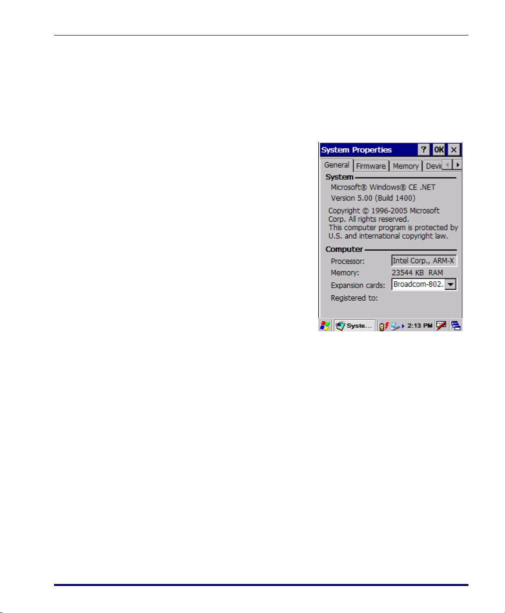
System Properties
Refer to the System control panel for information related to the system.To
view the System properties, select
erties.
General Tab
To view the expansion card settings,
select
Start > Settings > Control Panel >
System
Properties > General tab.
System Properties
Start > Settings > Control Panel > System Prop-
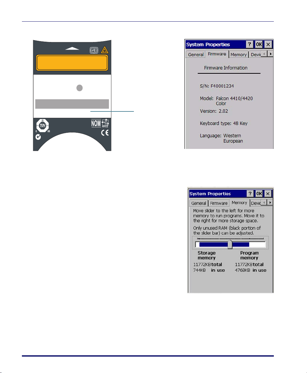
Firmware Tab
Select Start > Settings > Control Panel > System Properties > Firmware tab to view
the device serial number, model number, firmware version, and keyboard type.
The serial number is also displayed on the safety label on the scanning pod.
Product Reference Guide 2-35
Page 52
Configuring the Falcon
Serial Number
SERIAL #FLYYDDDXXX
Figure 2-23. Serial Number Locations
A
V
O
I
D
E
X
P
O
S
U
R
E
Datalogic Mobile
1505 Westec Dr.
Eugene, OR 97402
— LASER LIGHT IS EMITTED FRO
PRODUCT OF USA
Complies with 21CFR and Part 15 of FCC rules.
Item # 345-4201-005
M
DATE OF MANUF
E
R
U
T
R
E
P
A
S
I
H
T
EUR: CE0560RADIO: BREEZECOM
CAN: 24611032079A
FCC: M52PCRNZZ-00
SERIAL # FLYYDDDXXX
Production
monitored
BACKUP BATTERY: 3.1 V Lithium
Safety
tested
Approved RLAN Module inside
N263
PRODUCT SERVICE
NRTL
9
2
,
7
8
3
,
4
:
T
A
P
6
4
,
0
4
,
1
-
2
6
0
8
-
1
,
3
9
5
,
4
-
7
4
,
7
5
8
,
7
1
7
-
5
,
1
3
0
,
5
2
0
Memory Configuration
RAM Memory Allocation and Usage
Complete the following steps to adjust
the
Memory Allocation (RAM Memory):
1. Select
Start > Settings > Control
Panel > System Properties
.
2-36
2. Select the
Memory tab.
3. Move the slider to adjust memory allocation.
4. Tap
OK, or <Enter> on the Falcon
Falcon® 4400 Series with Windows® CE
Page 53

Device Name
Your device uses this information to
identify itself to other computers.
Copyrights
Refer to this tab for specific copyright
data. As a user, you are responsible to
read this statement.
System Properties
Product Reference Guide 2-37
Page 54
Configuring the Falcon
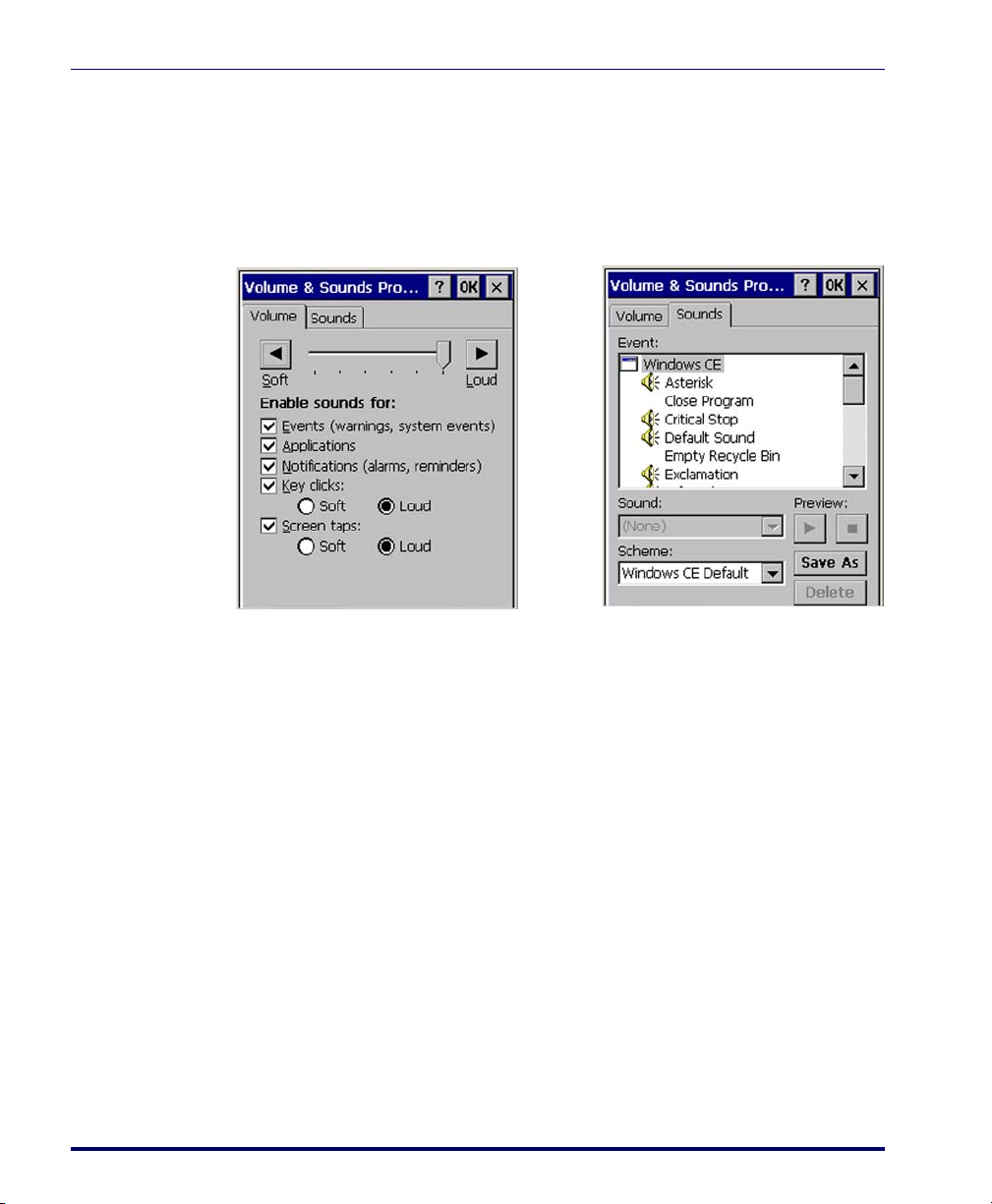
Volume and Sounds
To c h an g e t h e Volume and Sound settings, complete the following steps:
1. Select
Figure 2-24. Volume and Sounds Control Panels
Start > Settings > Control Panel > Volume & Sounds Properties to
open the
Volume settings.
2-38
2. Set the volume by adjusting the slider from Soft to Loud.
3. Enable the desired sounds for key clicks, screen taps, notifications,
and applications.
4. Select the
5. You can listen to the sound by selecting
6. Save your new sound scheme by selecting
Sounds tab to choose from various wave files in the menu.
Preview.
Save As and entering a
name for your new Sound Scheme in the field. Delete a sound scheme
by tapping
7. Tap
Delete.
OK when finished modifying your volume and sounds properties.
Falcon® 4400 Series with Windows® CE
Page 55

Wi-FI
About the Summit Client Utility
The Summit Client Utility (SCU) is an application designed for end users and
administrators of mobile devices that use a Summit radio module. For further
information beyond the scope of this manual, you can download the complete
Summit User’s Guide from www.summitdatacom.com.
Reference the QRG for details about the basic functions of this utility. After
completing an administrator login to the utility, you can perform these additional tasks:
• Create, rename, edit, and delete profiles
• Alter global settings, which apply to every profile
SCU provides a graphical user interface (GUI) for access to all of its functions.
Access to these functions also is available through an application programming
interface (API), which an application programmer can use to enable another
utility to manage the radio.
To initialize SCU:
Wi-FI
1. Go to Start> Settings > Control Panel.
2. Tap on the Wi-fi icon.
SCU Windows
SCU has five tabs: Main, Profile, Status, Diags (Troubleshooting), and Global
Settings. Tabs enable easy navigation. Each tab is described in more detail in
this section.
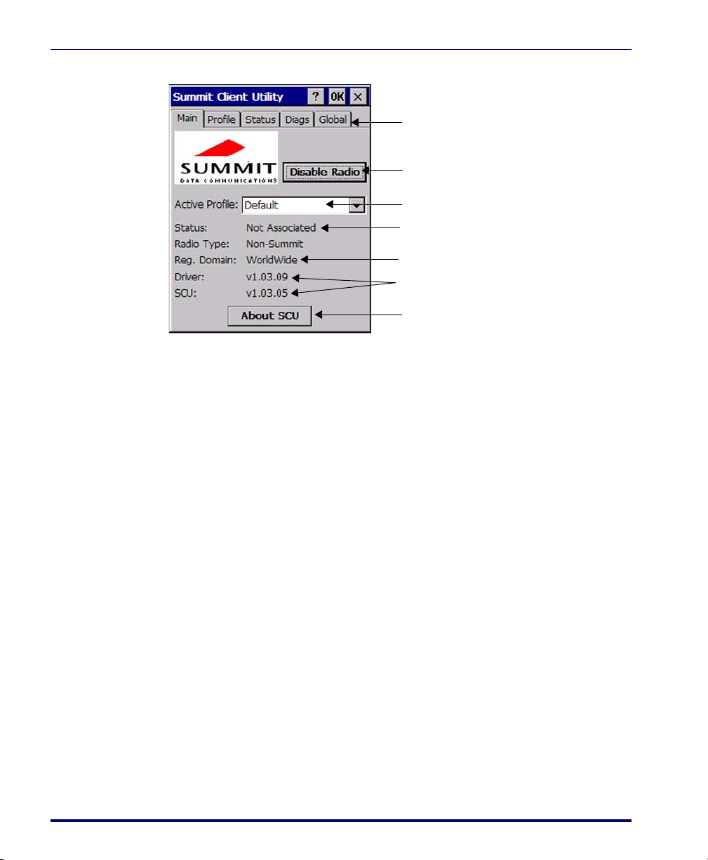
Main Tab
Reference Figure 2-25 on page 2-40 to view the features of the Main tab.
•
Enable/Disable Radio: Select or deselect to enable or disable the radio.
•
Active Profile: Displays the name of the active configuration profile.
An administrator can use the selection list to select a different profile.
•
Association Status: Indicates if the radio is associated to an access point
and, if not, what the radio’s status is.
Product Reference Guide 2-39
Page 56
Configuring the Falcon
Enable/Disable Radio
Active Profile
Association Status
Regulatory Domain
Software Versions
About SCU
Tabs
Figure 2-25. Main tab
• Regulatory Domain: Indicates the regulatory domain or domains for
which the radio is configured. “Worldwide” means that the radio can
be used in any domain. The domain cannot be configured by an
administrator or user.
2-40
Software Versions: Indicates the version of the device driver and the
•
version of SCU that are running on the device.
•
About SCU: Supplies information on SCU.
Profile Tab
Profile settings are radio and security settings that are stored in the registry as
part of a configuration profile. When a profile is selected, its settings become
active. An administrator can define, edit, or delete up to 20 profiles in the Profile tab in SCU. Profile changes made are saved only when the
is pressed.
Figure 2-26 on page 2-41 is an example of a Profile tab. Here are the highlights:
•
Profile: Use to select the profile to be viewed or edited. If “ThirdParty-
Config” is selected then, after the device goes through a power cycle,
WZC is used for configuration of the radio.
•
Actions: Four actions are available to an administrator:
- Rename: Give the profile a new name, one that is not assigned to
another profile
Falcon® 4400 Series with Windows® CE
Commit button
Page 57
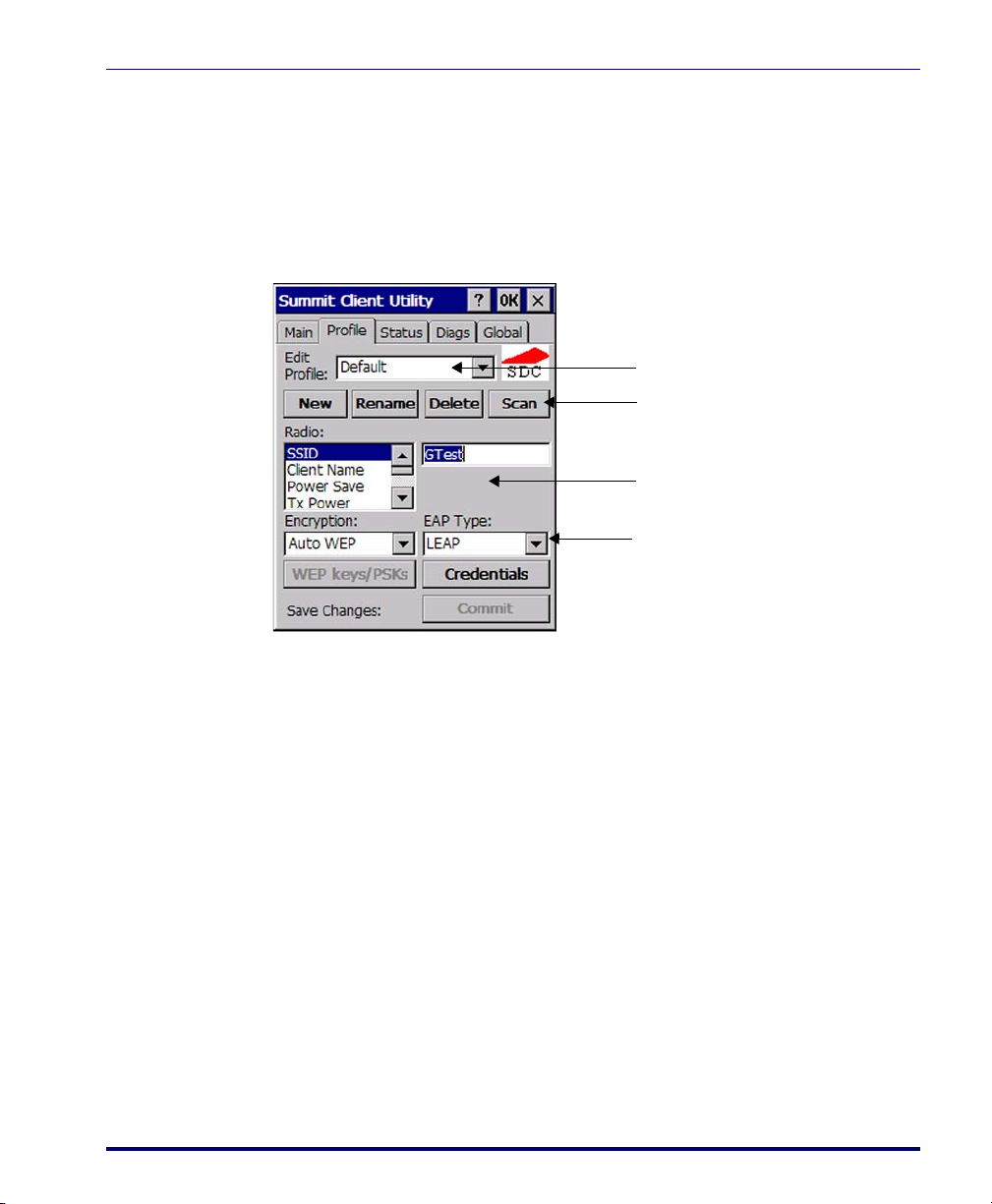
- Delete: Delete the profile, provided that it is not the active profile
Profile
Actions
Radio Attributes & Settings
Security Settings
- New: Create a new profile with default settings and give it a name
(and then change settings using other selections on the tab)
- Commit: Ensure that changes to profile settings made on the tab are
saved in the profile
Figure 2-26. Profile tab
Wi-FI
3. Radio attribute and setting: Attributes in the list box can be selected
individually. When an attribute is selected, the current setting or an
appropriate selection box with the current setting highlighted appears
on the right. For example, selecting SSID causes an edit box to
appear; selecting transmit power causes SCU to display a drop-down
list box with available settings.
Security settings: The items at the bottom of the tab enable the admin-
4.
istrator to configure the settings for EAP Type (used for 802.1X
authentication) and Encryption.
To connect a Summit radio to a typical business WLAN, you must select a
profile that specifies the SSID, EAP type, and encryption type supported by
the WLAN:
• SSID: The name or identification of the WLAN.
• EAP type: The protocol used to authenticate the device and its user if
the WLAN uses the Enterprise version of Wi-Fi Protected Access
(WPA) and WPA2. SCU supports four EAP types: PEAP with EAP-
Product Reference Guide 2-41
Page 58

Configuring the Falcon
Consult the Summit User’s Guide for details on all profile settings, including
security settings.
Status Tab
The Status tab shown in Figure 2-27 on page 2-43 provides status information
on the radio. Status items include IP address and MAC address for the client
radio, IP address and MAC address for the AP, signal strength, channel, transmit power, and data rate. A sample Status tab is shown in Figure 2-27 on page
2-43.
MSCHAP (PEAP-MSCHAP), PEAP with EAP-GTC (PEAP-GTC),
LEAP, and EAP-FAST
• Encryption: Specifies the type of key used to encrypt and decrypt
transmitted data and how that key is specified or derived. Encryption
options include:
- WPA2 or WPA with dynamic keys (derived from the EAP authenti-
cation process)
- WPA2 or WPA with pre-shared keys
- Static WEP keys
•
Client info: Name of active profile, client name, client IP address, and
client MAC address
•
AP info: AP name, AP IP address, and AP MAC address
•
Connection info: Channel, transmit power, and bit rate
2-42
One status item, the radio association state, is shown on both the Status tab
and the Main tab. Potential values are: Down (not recognized), Not Associated, Associated, or [EAP type] Authenticated.
Falcon® 4400 Series with Windows® CE
Page 59

Wi-FI
Client info
AP info
Connection info
Ping address
Ping results
Figure 2-27. Status tab
Diags Tab
A sample Diags, or troubleshooting, tab is shown in Figure 2-28 on page 2-43.
Figure 2-28. Diags tab, with ping active
Here are the functions available on the Diags tab:
•
(Re)connect: Disable and enable the radio, apply or reapply the
current profile, and attempt to associate and authenticate to the
wireless LAN, logging all activity in the output area at the bottom.
Product Reference Guide 2-43
Page 60

Configuring the Falcon
Global Settings Tab
Global settings include:
An administrator can define and change most global settings on the Global
Settings tab in SCU. Figure 2-29 shows a sample Global Settings tab.
Figure 2-29. Global Settings
• Release/Renew: Obtain a new IP address through DHCP release/
renew, and log all activity in the output area at the bottom.
Start Ping: Start a continuous ping to the address in the edit box
•
next to it. Once the button is clicked, its name and function will
change to Stop Ping. Leaving the Diags tab also will stop the ping,
as will pressing any other button on the screen.
•
Diagnostics: Attempt to (re)connect to an AP, and provide a more
thorough dump of data than is obtained with (Re)connect. The
dump will include radio state, profile settings, global settings, and
a BSSID list of APs in the area.
• Radio and security settings that apply to all profiles
• Settings that apply to SCU itself
2-44
The default setting for each global setting ensures reliable operation in most
environments. Consult the user’s guide for details on all global settings.
Falcon® 4400 Series with Windows® CE
Page 61

Overview
Chapter 3
Software Applications
This section contains the following topics:
•"Inbox" starting on page3-2.
• "Internet Explorer" starting on page 3-3.
• "Media Player" on page 3-4.
• "WordPad" starting on page 3-4.
• "Installing Programs" starting on page 3-5.
• "Using an Installation Wizard" starting on page 3-5.
• "Installing Programs Manually" on page 3-5.
• "Using Windows Explorer to Add to the Start Menu" on
page 3-6.
• "Using ActiveSync to Add to the Start Menu" on page 3-7.
• "Removing Programs" starting on page 3-7.
• "Firmware Update Utility" on page 3-7.
• "Retrieving a Firmware Image Update" on page 3-8.
• "Installing FUU on the Host PC" on page 3-8.
• "Updating the Falcon Firmware" on page 3-9.
• "Restoring Falcon Firmware" on page 3-10.
•"AutoStart" on page3-12.
Product Reference Guide 3-1
Page 62

Software Applications
Inbox
The Falcon comes with Inbox for Windows CE installed from the factory. Inbox
is a familiar Microsoft email interface. To set up your
Inbox:
1. Open
2. Select
Inbox by selecting Start > Programs > Inbox.
Services > Options from the
command bar to configure email.
3. Drag the screen to show
Add....
Select
4. Select the
Service Type and type
the email service name in the
vice Name
text box. Select OK.
Add....
Ser-
5. Enter the server and user information in the
tion
.
Mail Service Defini-
6. Configure your inbox using the
Mail General Preferences dialog.
7. Configure your mail retrieval settings in the
8. Tap
OK to complete the Inbox configuration.
9. Select
10. Select
Mail Inbox Preferences.
Services > Connect from the command bar.
Services > Send/Receive Mail from the command bar to manually
retrieve mail. Pending email appears in the inbox after connecting.
3-2
Falcon® 4400 Series with Windows® CE
Page 63

Internet Explorer
Internet Explorer window with the
Status bar and View menu.
Internet Explorer window with the
Status bar and View menu hidden.
The Falcon comes with Internet Explorer
for Windows CE installed.
Internet Explorer
1. Open
Internet Explorer by select-
ing
Start > Programs > Internet
Explorer
.
2. To set a default home page,
navigate to the desired default
web page.
3. Select
View > Internet Options
from the command bar.
4. Enter the desired URL in the
Start Page field.
5. Tap
OK.
Internet Explorer uses sliding menus for
application and navigation control. Tap
and drag the sliding menus to the left or right to see the hidden menu items
and toolbars.
To achieve more screen real estate in
Internet Explorer, you can hide the
tus
bar and View menu. From the top
menubar, go to
View > Hide Toolbars.
Sta-
Once it is hidden, you must cold reset
to access these features again. Refer to
the Falcon 4400 Series Quick Reference
Guide (QRG) for reset instructions.
Product Reference Guide 3-3
For more fine grained control over the
way Internet Explorer is displayed, refer
to Falcon® Desktop Utility for Windows® CE, starting on page B-1
Page 64

Software Applications
Media Player
The Falcon comes with Media Player for
Windows CE installed.
WordPad
1. Open
2. Select
Media Player by selecting
Start > Programs > Media Player.
File > Open to open an
available existing media file.
3. Please refer to
www.microsoft.com
for addi-
tional information and help with
your Microsoft Windows
Player.
Media
The Falcon comes with WordPad for Windows CE installed from the factory. The
following text and document file types are
compatible with
WordPad:
•Text (*.txt)
•Word Document (*.doc)
• Rich Text File (*.rtf)
•WordPad (*.pwd)
3-4
When file types other than *.pwd are
transferred to the device, Windows CE
translates the files into a compressed file
type.
To s t ar t
Microsoft WordPad
WordPad, select Start > Programs >
.
Falcon® 4400 Series with Windows® CE
Page 65

Installing Programs
Programs pre-installed on the Falcon are stored in ROM (read-only memory).
You cannot remove or modify this software.
You may add programs and data files to RAM (random access memory) or
into Flash memory via the FlashFX Disk. You can install *.cab, *.exe
*.zip files, or other files designed for the Falcon.
Please follow the directions provided with the software to install it.
Using an Installation Wizard
If the file has an installer, the installation wizard begins automatically if you
have ActiveSync installed. Most installation programs require an ActiveSync
connection. (Refer to "Installing & Setting Up Microsoft ActiveSync" on
page 4-1.)
Follow the directions on the screen. Once the software is installed on your
desktop computer, the installer transfers the software to your Falcon.
Installing Programs Manually
To quickly install programs on multiple Falcons, use the Falcon Management
Utility (
FMU). For more information, refer to page 2-16.
Installing Programs
If the file does not contain an installer, an error message indicates the program
is valid but is designed for a different type of computer.
• Install *.cab, *.exe *.zip, setup.exe files, or other files
designed for the Falcon.
• Windows CE applications will also work on the Falcon.
Start by downloading the program to your desktop computer (or insert the
CD or disk that contains the program into your desktop computer).
Product Reference Guide 3-5
Page 66

Software Applications
1. Select Start > Settings > Control
Panel > System > General
on the
Falcon. Make a note of the
information in the
Processor
field as shown at right. The
processor type is required to
determine file type compatibility.
2. Read the installation instructions, ReadMe files, or manual that comes with the
program. Many programs provide installation instructions.
• If you cannot find installation instructions for the program in the
ReadMe file or manual, use
ActiveSync Explore to copy the pro-
gram file to the Program Files folder on your Falcon.
• For more information on copying files using
ActiveSync online Help.
the
ActiveSync, refer to
3. Connect your Falcon and desktop computer. Refer to Networks,
Communications, and Connections, starting on page 4-1 to connect
your Falcon with your PC.
4. Double-click the *.exe or *.cab file.
5. Once the installation is complete, double-tap the program icon from
the desktop, or select
Programs > program icon to select it.
Refer to "Using ActiveSync to Add to the Start Menu" on page 3-7.
Using Windows Explorer to Add to the Start Menu
1. Select Start > Programs > Windows Explorer, and select the directory
where the application or program is stored.
2. Select
3. Open the Programs folder located in the Windows folder, select
The program appears on the menu.
3-6
Cut from the Edit menu.
Paste from the pop-up menu.
Falcon® 4400 Series with Windows® CE
Page 67
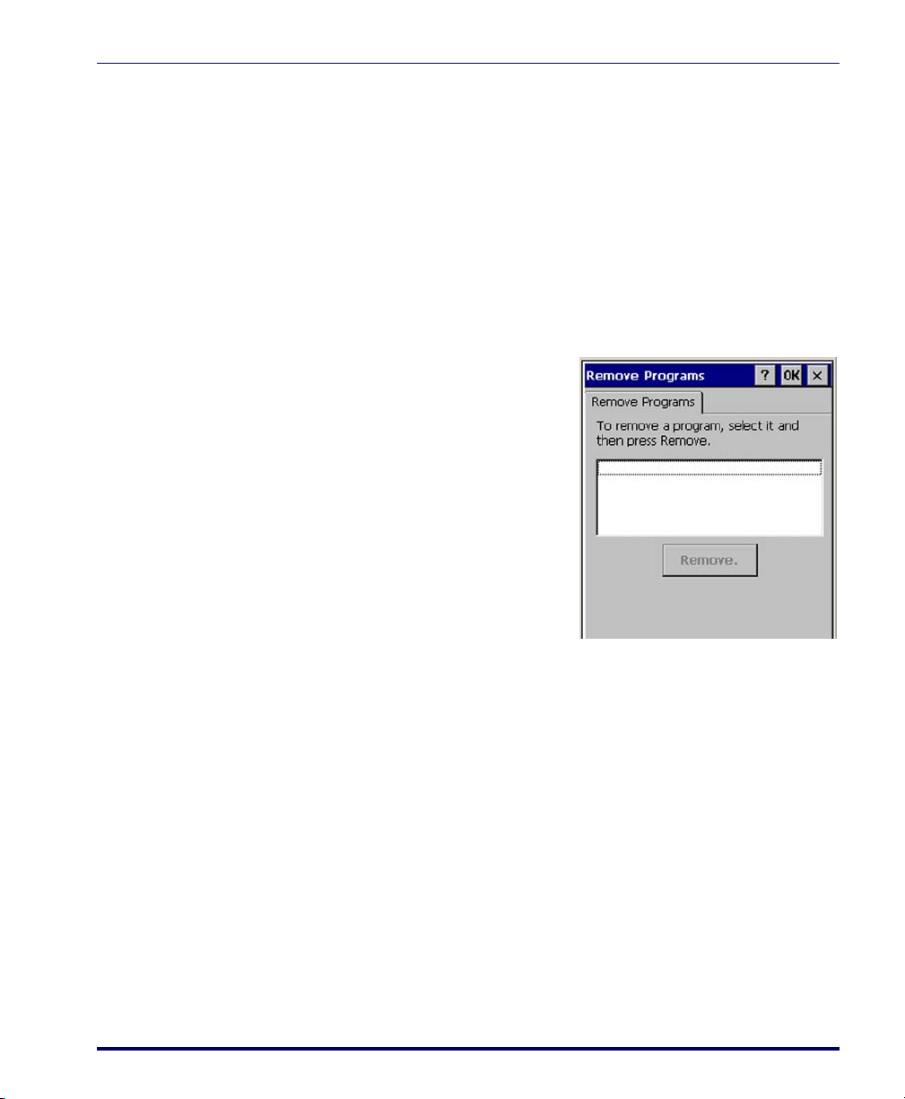
Using ActiveSync to Add to the Start Menu
1. Use the Explorer in ActiveSync on your desktop computer to explore
the files on your Falcon and locate the program. For more information on using
ActiveSync, refer to the ActiveSync online Help.
Removing Programs
2. Right-click on the program, then select
Move the shortcut to the Programs folder in the Windows folder. The
shortcut appears on the menu.
Removing Programs
Only user-installed programs can be
removed.
1. To remove a program, select
> Settings > Control Panel > Remove
Programs
2. Select the program you wish to
remove from the list and tap
Remove.
.
Firmware Update Utility
Create Shortcut.
Start
The Falcon is equipped with a field upgradeable firmware mechanism. Firmware updates for the Falcon are available on the Datalogic Mobile website
(www.mobile.datalogic.com). After you have downloaded the desired update,
there are several ways you can update the firmware on the Falcon.
• Use the Falcon Management Utility (FMU) if you have multiple Fal-
cons to update. Refer to the FMU User’s Guide on the Product CD
included with your Falcon for more information.
• If FMU is not available or you have only a few Falcons to update, use
the Firmware Update Utility (FUU), described below, to install or
update the firmware using an ActiveSync connection. Refer to
"Installing & Setting Up Microsoft ActiveSync" on page 4-1 for more
information.
Product Reference Guide 3-7
Page 68

Software Applications
FUU can also be used to restore the firmware onto a Falcon that has become
corrupted, such as would happen if the Falcon were powered down during an
ActiveSync firmware update. See "Restoring Falcon Firmware" on page 3-10.
The following sections provide procedures for the retrieval and installation of
the most current firmware image onto a Falcon.
Retrieving a Firmware Image Update
The following instructions use Internet Explorer to retrieve the most current
firmware image.
1. Launch Internet Explorer on your PC and navigate to the Datalogic
Mobile website.
2. Navigate to the Downloads section of the website.
3. Select the file you want to download, then click Save to begin copying
the files to your local machine (or local network location).
Installing FUU on the Host PC
The Firmware Update Utility (FUU) provides administrators with a field
®
upgrade mechanism. You must have Microsoft
ActiveSync already loaded
and running on the host PC to use FUU. Refer to "Installing & Setting Up
Microsoft ActiveSync" on page 4-1 and "Using ActiveSync" on page 4-6 for
more information about ActiveSync.
Prior to installing FUU, you must remove any previous versions of FUU installed
on the host PC.
To install Datalogic Mobile’s Falcon
®
Firmware Update Utility, complete the
following steps on the PC:
1. Insert the CD ROM shipped with your Falcon and click on the link
to
Firmware Update Utility.
OR
Go to the Datalogic Mobile website and download the most current version of the Firmware Update Utility. Unzip the file, then double-click to
run FUU_Setup.exe
Click
OK to continue once you have removed previous versions of FUU.
2. The
Welcome to FUU Setup Program screen opens.
• Please exit all Windows applications before running this setup.
3-8
Falcon® 4400 Series with Windows® CE
Page 69
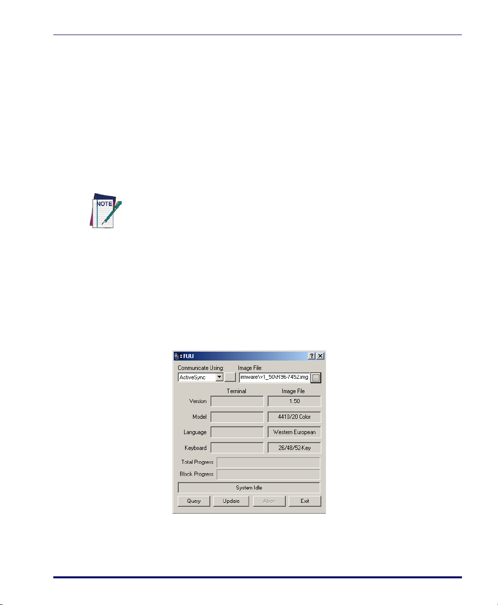
•Click Cancel to quit Setup and close any programs you have run-
ning.
•Click
Next to continue the Setup.
3. Follow the onscreen instructions to complete the installation.
Updating the Falcon Firmware
After copying the firmware image to the host PC ("Retrieving a Firmware
Image Update" on page 3-8) and installing
PC" on page 3-8), you can upgrade the firmware on your Falcon.
The following steps require that you have already established an ActiveSync connection between the host computer and the Falcon. To establish an ActiveSync
connection with the Falcon, refer to "Installing & Setting Up Microsoft ActiveSync" on page 4-1 and "Using ActiveSync" on page 4-6, for more information on
ActiveSync.
Firmware Update Utility
FUU ("Installing FUU on the Host
1. Go to
Start > Programs > Firmware Update Utility > Firmware Update Utility.
2. Verify that ActiveSync is selected from the
down list.
3. Click browse (
...) and navigate to the location where you saved the
firmware file for your terminal.
4. Select the current *.img file and click
Open.
Communicate Using pull-
Product Reference Guide 3-9
Page 70
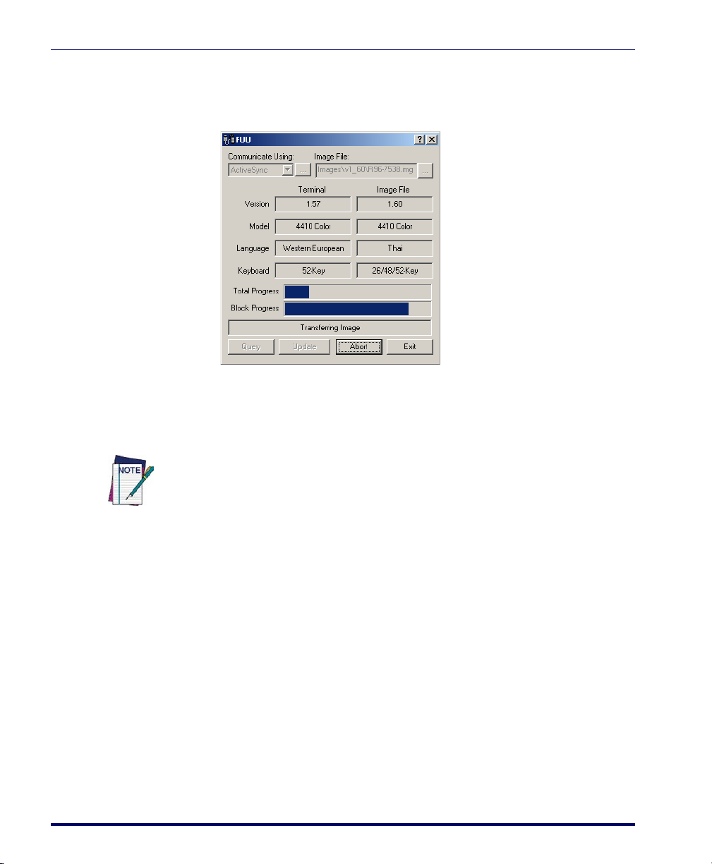
Software Applications
5. Verify that the Falcon is turned on. Insert the device into a powered
dock connected to the host computer.
6. Click
7.
Update Terminal on FUU on the host PC.
FUU will compare the selected firmware image with the firmware
already loaded on the Falcon; if the images are different,
FUU will pro-
ceed to update the firmware image on your Falcon.
Please be patient and do not remove the Falcon from the Dock during this procedure. The firmware image of the Falcon can take as long as:
• 12 minutes to download using a USB connection.
• 22 minutes to download using a serial connection with 115K baud rate.
• 130 minutes to download using a serial connection with 19.2K baud rate.
8. After the firmware of your Falcon has been updated, you must perform a warm reset of the Falcon. Refer to the Falcon 4400 Series Quick
Reference Guide (QRG) for reset instructions.
Restoring Falcon Firmware
If the firmware image on the Falcon becomes corrupted, the Falcon will beep
twice and show a blank screen when powered on. This can happen if a firmware update is aborted, such as during a power loss or if the Falcon is removed
from the Dock before completion of the procedure.
To reinstall the firmware, complete the following steps:
3-10
Falcon® 4400 Series with Windows® CE
Page 71
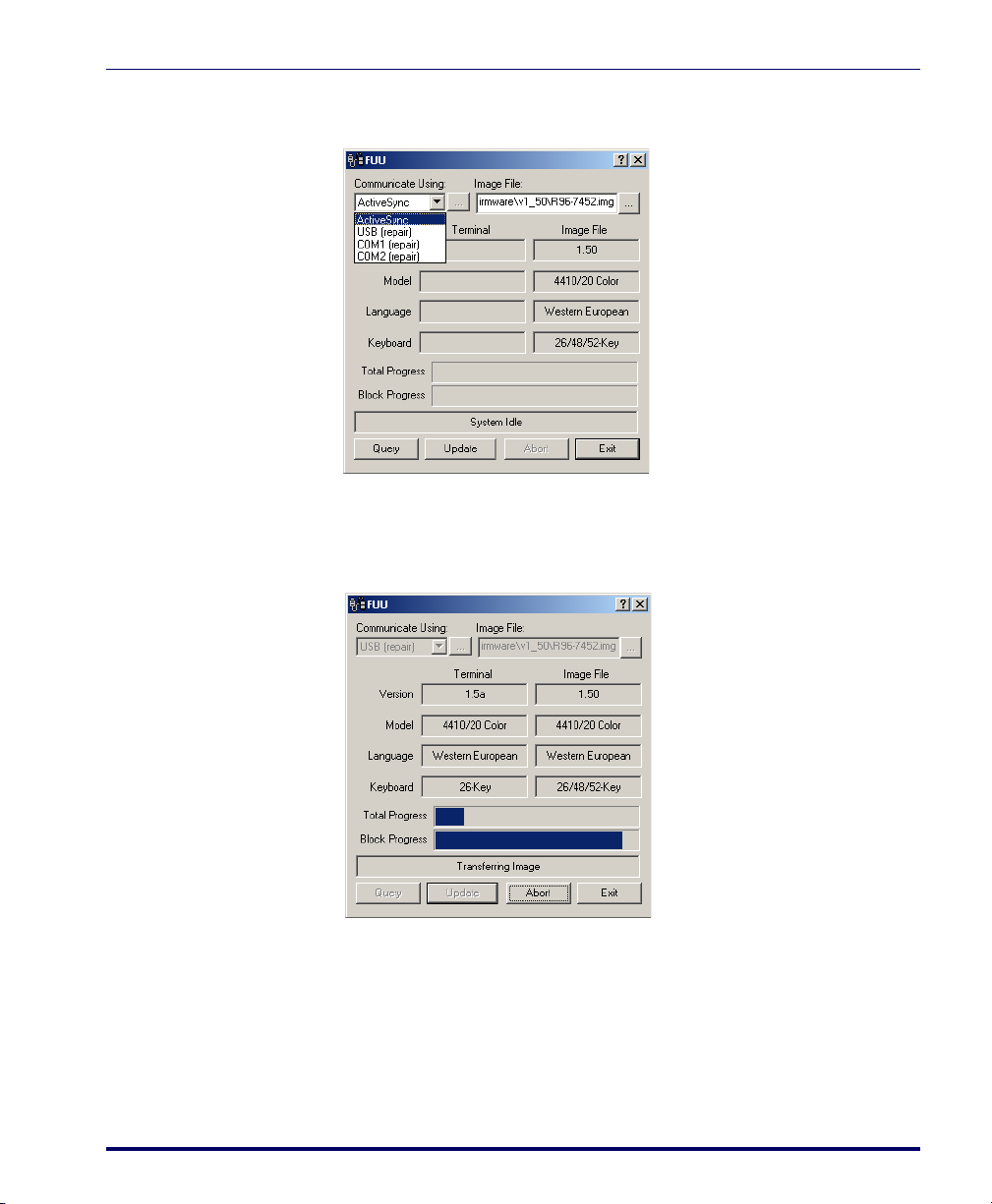
Firmware Update Utility
1. On the PC, click Start > Programs > Firmware Update Utility > Firmware
Update Utility
.
2. Set
Communicate Using to the communications port to which the dock
is attached to (ActiveSync, USB, COM1 or COM2.)
3. Click browse (
4. Select the current *.img file and click
...) and navigate to the file location.
Open.
5. Verify that the Falcon is turned on. Insert the Falcon into a powered
dock connected to the host computer.
6. Click
7.
Update Terminal on FUU on the host PC.
FUU will restore the firmware on the Falcon as shown on page 3-9.
Product Reference Guide 3-11
Page 72

Software Applications
Please be patient and do not remove the Falcon from the Dock during this procedure. The firmware image of the Falcon can take as long as:
• 12 minutes to download using a USB connection.
• 22 minutes to download using a serial connection with 115K baud rate.
• 130 minutes to download using a serial connection with 19.2K baud rate.
AutoStart
The AutoStart program provides three functions:
AutoStart launches each time the Falcon is rebooted. AutoStart first runs
PreAuto.ini (reference Tab l e 3 -2 for the location), executing each line
with the specified command line arguments. It will take into account any
AutoStart options at the begining of the line.
8. After the firmware has been restored, the Falcon will automatically
reset.
• Allows you to create a list of applications (with optional command
line arguments) to run automatically prior to loading CAB files.
• Automatically reinstalls specified CAB files when the Falcon is Hard
Reset.
• Allows you to create a list of applications (with optional command
line arguments) to run automatically after loading CAB files.
3-12
Upon a Cold Reset, AutoStart installs all the CAB files located in the
AutoStart CAB folder. If the AutoStart CAB folder does not exist, no CAB
files will be installed.
Table 3-1. AutoStart CAB folder location
Product Operating System Location
F4400
Windows CE
Windows Mobile
\FlashFX Disk
\FlashDisk
AutoStart will then run the Autostart.ini (reference Tab le 3 - 2 for the
location), executing each line with the specified command line arguments. It
will take into account any AutoStart options at the beginning of the line.
Falcon® 4400 Series with Windows® CE
Page 73

Table 3-2. PreAuto.ini and Autostart.ini location
F4400
Installing CAB files
Copy any CAB files you want to install into the AutoStart CAB folder. These
CAB files will then be automatically installed in alphabetical order the next
time you start the device.
How AutoStart Uses Wceload
If you intend to create highly interactive installers, you should either install the CABs manually or
review the section on “Interactive CAB Install” in this chapter.
In certain environments, CAB files will be deleted after execution. To prevent the CAB file from
being deleted, write protect the file before copying the file onto the device.
CAUTION
Product Operating System Location
Windows CE
Windows Mobile
\FlashFX Disk
\FlashDisk
AutoStart
CAB files are installed by AutoStart using the Wceload.exe application.
Table 3-3 on page 3-13 shows available command line options:
Table 3-3. AutoStart command line options
Option Description
Specifies that you will not be prompted for any input during the installation. If
/noui
/silent Suppresses dialog boxes during the installation.
the CAB file is signed, any responses will automatically be answered ‘Yes.’ If
the CAB is unsigned, then any responses will be answered ‘No.’
Please refer to the Microsoft documentation on your device for further details
on Wceload.exe.
Sample:
\Windows\Wceload.exe /delete 1 /noui /silent
“\FlashDisk\CAB\<cab file>”
Product Reference Guide 3-13
Page 74

Software Applications
Interactive CAB Install
If the CAB installer requires user interaction that must be performed during
the AutoStart CAB installation process, you can specify a special file name to
disable the silent mode installation. If this mode is specified, the CAB file will
be installed with Wceload without any command line arguments specified.
An example of what AutoStart would execute is:
\Windows\Wceload.exe <cab file>
To force this mode of installation via AutoStart, rename the CAB file to
include a ‘_’ character before the “.cab” extension of the file.
Example:
“File.cab” should be renamed “File_.cab” to force AutoStart to not
install the CAB in silent mode. This specially-named CAB file should be
placed in the AutoStart folder with other CAB files intended for installation
on the next reboot.
Autostart.ini
Autoexec.ini, which uses AutoCE on some older models, has been deprecated. These files should
be renamed to Autostart.ini and reformatted as described in "AutoStart" on page 3-12.
In the following section, all references to AutoStart.ini also pertain to PreAuto.ini.
Autostart.ini and PreAuto.ini are text files that AutoStart will run
upon startup of the Falcon, and after any CAB files are installed. This file
should be placed in the AutoStart folder. AutoStart will run the
Autostart.ini file on each reboot of the device.
Line Formatting
Each line of the Autostart.ini can consist of Autostart options, an executable, and any command line arguments.
< Autostart option(s)> <full path to executable>
<command line arguments>
Sample:
- \windows\pword.exe \file.doc
Ta bl e 3 - 4 breaks down the sample Autostart.ini line.
3-14
Falcon® 4400 Series with Windows® CE
Page 75

AutoStart
Table 3-4. Autostart.ini line formatting
Autostart
option(s)
- \windows\pword.exe \file.doc
Full path to executable Command line arguments
Spaces must be placed between each component of the line in the
Autostart.ini.
If the executable path is in a folder that contains spaces in the name, quotes are
required to distinguish what the actual executable name is. The following is an
example of this:
“\Program Files\ScannerApp.exe” /run (valid)
\Program Files\ScannerApp.exe /run (invalid)
The second line is an invalid line because there is no way to distinguish the
executable from the argument.
AutoStart Options
Ta bl e 3 - 5 shows options you can use when writing a line in the
Autostart.ini or PreAuto.ini file.
Table 3-5. Options for Autostart.ini and PreAuto.ini
Description Character Comments
This may only be used as the first
Comment: This line will not be executed.
Do not wait on line completion:
This will cause the line to execute
and immediately move onto the
next line.
Query: Request user confirmation
when running the executable.
Execute only on Cold Reset ‘!’
Product Reference Guide 3-15
‘#’ OR ‘ ‘
(space)
‘-’
‘?’
character of the line. If the comment
option is specified in the options
elsewhere, it is ignored.
This will halt parsing the
Autostart.ini until the confirmation is
answered. This is intended for
debugging the Autostart.ini file.
Page 76

Software Applications
Cold Reset Only: This will cause the line to execute only after a Cold
Reset.
An empty line will be treated as a comment line.
Combining Options
Autostart options can be combined together as shown in the following sample:
?- \Windows\Pword.exe
This line would:
• Request confirmation before executing the line. The next line would
not be processed before the confirmation is answered.
• Run the next line without waiting on the current line to complete
execution.
Query Option
The query option is intended for use when debugging the
autostart.ini. When a line with this option is executed, the following
dialog will appear with the specified executable and command line arguments.
The populated fields shown in the AutoStart Execute Query are described in
Table 3-6 on page 3-17.
3-16
Falcon® 4400 Series with Windows® CE
Page 77

AutoStart
AutoStart Execute Query
.
Table 3-6
Line Number This is the line number in the script being executed.
Exe The executable as parsed by AutoStart.
Args The argument as parsed by AutoStart.
The fields may be broken up into multiple lines (as shown in the example) due to limited space in
the dialog.
AutoStart Query options
Field Description
Parentheses are used to surround the given field and make it very clear what
the value of the field is.
Ta bl e 3 - 7 describes the results of each choice:
Table 3-7. AutoStart Query actions
Button Action
Yes The current line will execute.
No
Cancel
Autostart.ini Samples
The current line will not execute. AutoStart will continue parsing the
Autostart.ini.
The current line will not execute and AutoStart will discontinue
parsing the Autostart.ini.
Table 3-8 on page 3-18 is a collection of sample Autostart.ini lines.
Product Reference Guide 3-17
Page 78

Software Applications
Table 3-8. Sample Autostart.ini lines
Line Description
? \windows\wceload.exe “\My
Documents\FDU.cab”
\Program Files\App.exe
\Program Files\App.exe /run
“\Program Files\App.exe” /run
?- \Windows\Pword.exe
!”\Program Files\App.exe” /run
This will confirm the execution of \Windows\wce-
load.exe
with specified argument “\My Docu-
ments\FDU.cab”
(invalid) This will execute \Program with the argu-
ment
Files\App.exe.
(invalid) This will execute \Program with the argu-
ment
Files\App.exe /run.
This will execute the program \Program
Files\App.exe
This will confirm the execution of \Win-
dows\Pword.exe
AutoStart will immediately process the next line.
This will execute the program \Program
Files\App.exe
after a Cold Reset.
with the argument /run.
. If the execution is confirmed,
with the argument /run ONLY
3-18
Falcon® 4400 Series with Windows® CE
Page 79

Networks, Communications,
Overview
Chapter 4
and Connections
This section contains the following topics:
• "Installing & Setting Up Microsoft ActiveSync" starting on page 4-1.
• "Installing Microsoft ActiveSync" on page 4-2.
• "Setting Up ActiveSync" on page 4-4.
• "Installing the USB Driver" on page 4-5.
• "Using ActiveSync" starting on page 4-6.
• "Networking" starting on page 4-8.
• "Setting Up the Network ID" starting on page 4-8.
• "Network and Dialup Connections" starting on page 4-9.
• "SNMP" starting on page 4-9.
Installing & Setting Up Microsoft ActiveSync
This section provides instructions on setting up the Host PC so that the PC
can communicate with the Falcon and the dock.
The screen shots in the manual were taken and the procedures were written using
®
Windows
and procedures may be slightly different.
Important! You must disconnect any other PDAs, PDTs, or Falcons using USB
ActiveSync from the Host PC prior to connecting the Falcon or the Host PC and
Microsoft ActiveSync may not recognize the new device.
Product Reference Guide 4-1
XP. If you are using Windows® 2000 or Windows® NT, appearances
Page 80

Networks, Communications, and Connections
Installing Microsoft ActiveSync
Microsoft® ActiveSync is a file transfer tool used to synchronize the files on a
PC with the files on your Falcon. The device comes from the factory with
ActiveSync loaded. If you have ActiveSync already installed on your PC, make
sure that you have v3.7.1 or higher.
To install Microsoft
1. Go to the Microsoft
http://www.microsoft.com/downloads/.
®
ActiveSync on the PC, complete the following steps:
®
Windows CE website at
2. Use the
Product/Technology pull-down list to search on “ActiveSync”
for the most current version.
3. Download the current version of ActiveSync from the Microsoft website.
Figure 4-1. Microsoft ActiveSync Installer
4. Install the most current version of Microsoft® ActiveSync (v3.7.1 or
higher) on the host PC (refer to Figure 4-1 on page 4-2).
4-2
Falcon® 4400 Series with Windows® CE
Page 81

Installing & Setting Up Microsoft ActiveSync
Figure 4-2. Microsoft ActiveSync Installer
5. Click Next to continue the installation. Click Cancel to cancel the
installation of ActiveSync.
Figure 4-3. Microsoft ActiveSync Installer
6. Reboot your PC.
7. You have completed installing ActiveSync.
Product Reference Guide 4-3
Page 82
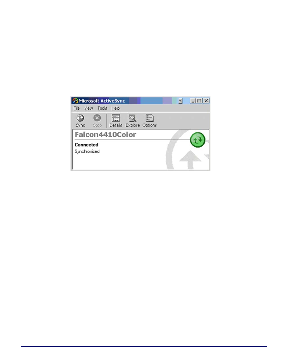
Networks, Communications, and Connections
Setting Up ActiveSync
1. Open ActiveSync from the System Tray of the Host PC.
2. Connect the Falcon to the Host PC via a dock or USB/Serial cable.
3. Verify that the Falcon is turned on.
4. Within a minute, the ActiveSync window should appear, attempting
to connect to a new device.
Figure 4-4. Microsoft ActiveSync dialog
5. If ActiveSync does not connect within two minutes, try the following:
• Double-click and open
Tray if it is not already open.
• Remove the Falcon from the dock and then reinsert it into the
dock or disconnect the cable from the Host PC and reconnect it.
• Select
•Go to
File > Get Connected for ActiveSync to look for a mobile
device.
File > Connection Settings and make sure that your Connec-
tion Settings dialog show the same selections as that in Figure 4-5
below if you have a USB connection. If you have a serial connection, select the correct COM port from the pull-down list.
ActiveSync from the Host PC’s System
4-4
Falcon® 4400 Series with Windows® CE
Page 83
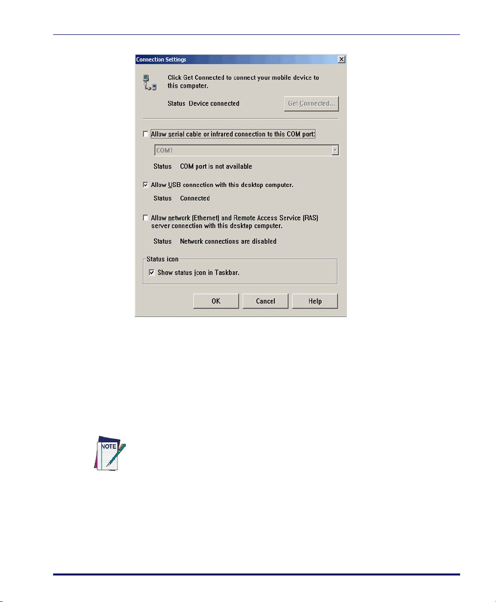
Figure 4-5. Connection Settings
Installing the USB Driver
6. You have completed setting up ActiveSync. Proceed to Installing the
USB Driver, below, to install the USB driver.
Installing the USB Driver
In order for the Host PC to communicate with the Falcon, you must install
the USB driver file from the CD that came with the Falcon.
Microsoft ActiveSync must be installed on your computer before proceeding. See
"Setting Up ActiveSync" on page
Important! Install the USB driver PRIOR to connecting the Falcon to the host PC.
1. Copy the current USB driver file from your Falcon CD or the Data-
logic Mobile website to the following location on your computer:
C:\Program Files\Microsoft ActiveSync\Drivers.
Product Reference Guide 4-5
4-4.
Page 84

Networks, Communications, and Connections
2. Connect the USB or Serial cable to Falcon or place the Falcon in the
dock.
3. Connect the USB or Serial cable to a Host PC.
4. Follow the directions onscreen. The specified source directory will be
the one identified in step 1.
You are now ready to use ActiveSync.
Using ActiveSync
Use ActiveSync to transfer and synchronize (share) files between the Falcon
and the Host PC.
File Synchronizing using ActiveSync
ActiveSync file synchronization requires an ActiveSync partnership between
the Falcon and the Host PC. Refer to the ActiveSync online help for more
information.
1. Select the controls in the synchronization configuration for the Falcon
partnership. Refer to Figure 4-6 on page 4-7.
2. Select
Tool s > O p tions from the ActiveSync command bar to configure
the synchronization options.
4-6
Falcon® 4400 Series with Windows® CE
Page 85
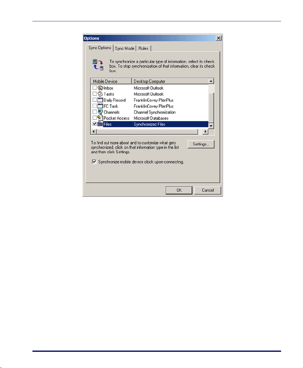
Figure 4-6. File Synchronization Options
Using ActiveSync
3. Place the file to be synchronized in the Synchronization folder
created in your My Documents directory (defaults to the desktop).
Refer to Figure 4-7 on page 4-8.
During the ActiveSync connection, all files in the Synchronization
folder will be synchronized with (copied to) the \My Documents directory
on the Falcon.
Product Reference Guide 4-7
Page 86
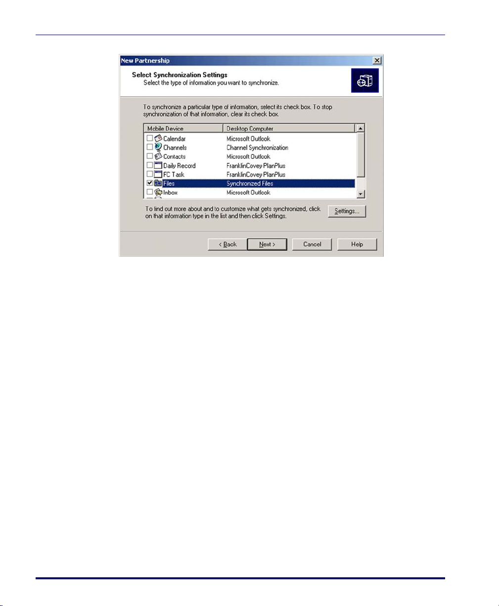
Networks, Communications, and Connections
Figure 4-7. Select Synchronization Settings
Networking
Setting Up the Network ID
To set up your Network ID (configure the Windows user settings, such as the
user name, password, and domain), complete the following steps on the Falcon:
1. Go to
2. Select the
3. Enter your
4. Select
Start > Settings > Control Panel > Owner.
Network ID tab on the Owner Properties dialog box.
User Name, Password, and Domain on the Network ID tab.
OK on the command bar to save your network ID information.
Access basic network connection information by double-tapping on the
work
icon in the system tray. Tap Details to show more information.
The Network Icon
The network icon in the system tray indicates if the network is currently connected or not.
4-8
Net-
Falcon® 4400 Series with Windows® CE
Page 87
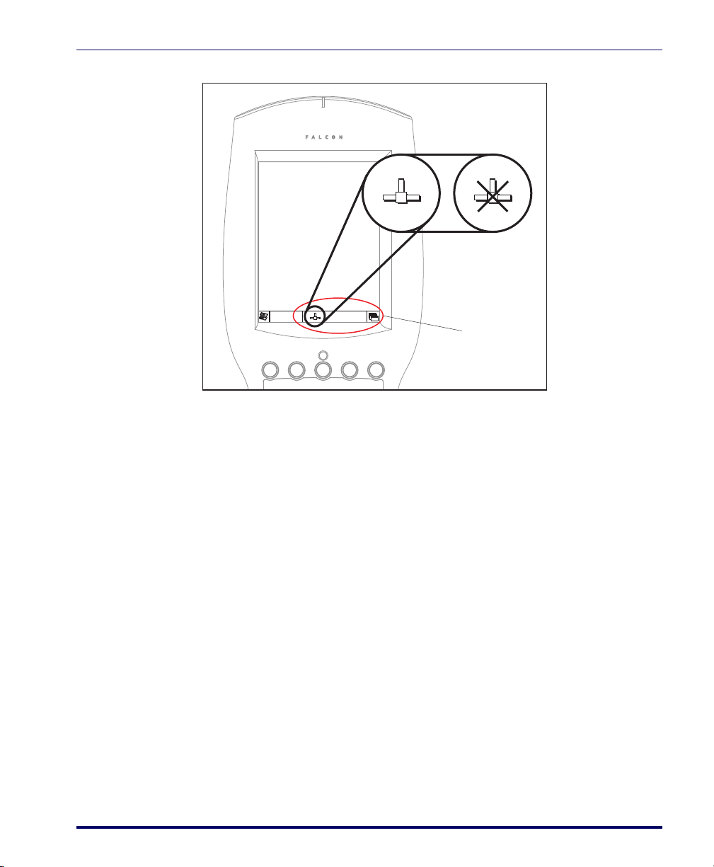
Figure 4-8. The Network Icon
11:57 AM
System Tray
Network
Connection Icon
Connected Not Connected
Network and Dialup Connections
SNMP
Use Network and Dialup setup to administer the IP network settings for specific connections. The system defaults to Summit Client Utility (SCU) for
wireless communications, and normal Windows Dialup and Networking for
all other network connections. See About the Summit Client Utility on
page 2-39 for more information on SCU.
Windows Zero Config
The Falcon can optionally be set to use Windows Zero Config, if preferred.
Refer to Microsoft online help for further information.
SNMP
SNMP (Simple Network Management Protocol) is the standard protocol for
managing devices on a network. The Falcon Management Utility (FMU)
makes use of SNMP to send and receive configuration information to the Datalogic Mobile terminals. Since the networked terminals are constantly running
SNMP, this allows FMU to interface with the terminal at any time, without
Product Reference Guide 4-9
requiring user intervention on the terminal.
Page 88

Networks, Communications, and Connections
With SNMP running on the terminal, other SNMP based network manage-
®
ment tools such as HP Openview
and CastleRock SNMPpc® may also be
used to interface with the terminals. To support this capability, Datalogic
Mobile has released the Management Information Base (MIB) for the Datalogic Mobile Windows-based terminals. The MIB is used by the management
tools to allow them to better support the configuration values provided on the
terminals, such as scanner controls and terminal type information.
The MIB is available at www.mobile.datalogic.com.
For more information on SNMP, refer to
SNMP Interface, or go to:
www.microsoft.com.
4-10
Falcon® 4400 Series with Windows® CE
Page 89

Overview
Appendix A
Accessories
This appendix covers the following topics:
• "Power Supplies" on page A-2.
• "Battery Pack" on page A-2.
• "Single-Slot Dock" on page A-2.
• "Four-Slot Dock" on page A-3.
•"Battery Charger" on pageA-3.
• "Serial Charging Cable" on page A-4.
•"USB Cable" on pageA-4.
•"Printer Cable" on pageA-4.
• "Serial Printer Adapter" on page A-4
• "Holsters and Softcases" starting on page A-6.
• "Holsters" starting on page A-6.
• "Softcases" starting on page A-7.
• "Installing the Handle or Handstrap" starting on page A-8.
• "Installing a Handle on the Falcon 4410" on page A-9.
• "Installing the Handstrap on the Falcon 4420" on page A-8.
•"Tethered Stylus" on pageA-10.
Contact your Datalogic Mobile reseller for accessories and supplies for the Falcon; you can see the options in this appendix or check the Datalogic Mobile website.
Product Reference Guide A-1
Page 90

Accessories
Power LED
USB/Serial Connector
Spare Battery
LED
Battery Pack in
Spare Battery
Charging Slot
Power Supplies
Use only the correct battery chargers and docks with this Windows CE color Falcon. This technology used for these models is incompatible with other Datalogic
Mobile Falcon chargers and docks.
Battery Pack
Figure A-1. 4-Battery Pack
Single-Slot Dock
Figure A-2. Single Slot Dock
A-2
Falcon® 4400 Series with Windows® CE
Page 91

Four-Slot Dock
Four-Slot Battery Charger
Figure A-3. Four-Slot Dock
Battery Charger
Power Supplies
Figure A-4. Li-Ion Battery Charger
Product Reference Guide A-3
Page 92

Accessories
USB Cable
See Figure E-1 on page E-1.
Serial Charging Cable
See Figure E-2 on page E-2.
Printer Cable
See Figure E-3 on page E-2.
Serial Printer Adapter
The Serial Printer Adapter attaches to the bottom of a Falcon unit and allows
you to print directly to a printer.
Figure A-5. Serial Printer Adapter
A-4
To attach the printer adapter to a Falcon, you must remove the strap studs, as
well as the optional strap stud bumpers, if present. Use the procedure that follows.
Falcon® 4400 Series with Windows® CE
Page 93

Power Supplies
Removing Strap Studs/Bumpers
Figure A-6. Strap Studs
Strap Stud
Bumpers
Strap Studs
1. Loosen and pull off the strap stud bumpers (if present). If necessary,
pry off using a screwdriver.
2. Use a 5/64” Allen wrench (included with the printer adapter) to
loosen and remove each Strap Stud.
Once you have removed the strap studs, attach the adapter to the Falcon by
tightening the thumbscrews on the adapter.
Figure A-7. Attaching the Serial Printer Adapter
Product Reference Guide A-5
Page 94

Accessories
• Quick release swivel belt
mount (clip on both sides for
left or right mount)
•Heavy duty nylon
Holsters and Softcases
A holster and a softcase are available that will work with both the Falcon 4410
and the handled Falcon 4420 models.
Holsters
Figure A-8. Three Holster Views
A-6
Falcon® 4400 Series with Windows® CE
Page 95

Softcases
Holsters and Softcases
Figure A-9. Softcase for Handled Falcon 4420
• Belt clip option
•Stylus holder
•Open cover
•Heavy duty nylon
• Scanner window
Product Reference Guide A-7
Page 96

Accessories
Cover
Plate
Retaining
Pin
Retaining Pin
is threaded
through loop
in strap and
seated in sockets
Handstrap
Handstrap
PDT
Cover
Plate
Installing the Handle or Handstrap
The Falcon 4420 comes from the factory with the handle installed. The Falcon
4410 comes with a handstrap. These can be exchanged with a change-out kit.
The handle is removable and can be replaced with a handstrap. When you
replace the handle with the handstrap, you lose the ability to press the trigger
on the handle and must use the
To remove the handle and replace it with the handstrap refer to the following
sections. Reverse the same directions to replace the handstrap with the handle.
Installing the Handstrap on the Falcon 4420
To install a handstrap on the Falcon 4420, complete the following steps:
1. Remove the handle as shown in Figure A-11 by removing the screws
located just above the battery cover’s latch dials.
2. Insert the top tab of the handstrap cover into the slot at the top of the
handle recess. (refer to Figure A-10)
Figure A-10. Removing/Replacing a Handstrap
<Scan> key on the Falcon keypad instead.
A-8
Falcon® 4400 Series with Windows® CE
Page 97

Installing the Handle or Handstrap
Handle
PDT
3. Replace the screws located just above the battery cover’s latch dials.
4. Connect the handstrap hook onto one of the strap studs at the base of
the Falcon.
5. The process is complete upon successful test of the scanning function.
Installing a Handle on the Falcon 4410
To install the handle on the Falcon 4410, complete the following steps:
1. Remove the handstrap as shown in Figure A-10 by removing the
screws located just above the battery cover’s latch dials.
Figure A-11. Removing/Replacing the Handle
Product Reference Guide A-9
Page 98

Accessories
Tet her
2. Insert the top tab of the handle into the slot at the top of the handle
recess (refer to Figure A-11).
3. Replace the screws located just above the battery cover’s latch dials.
4. The process is complete upon successful test of the trigger function.
Tethered Stylus
An optional Tethered Stylus is available
for use on any of the Falcon 4400
series models. The Tether attaches the
stylus to the Falcon unit, preventing
the stylus from accidentally becoming
lost or misplaced.
Installing a Tethered Stylus
If your Falcon did not come with a Tethered Stylus, it can be easily installed.
To install a Tethered Stylus on the Falcon 44xx complete the following steps:
1. Turn the Falcon face-down. Ensure that power is OFF.
2. Using a Phillips screwdriver, remove the 6 mm screw at the bottom of
the Stylus holder.
3. Use the longer 16 mm screw included with the Tethered Stylus kit to
attach the Tethered Stylus to the Falcon.
Do not use the 16mm long screw that came with the Tethered Stylus without the
Tether. Damage to internal components could occur if the screw is used without
the Tether, since the screw is longer than the standard 6 mm screw used without
CAUTION
A-10
the Tether.
4. Slide the other end of the Tether through the Stylus.
Falcon® 4400 Series with Windows® CE
Page 99

This completes Installation of the Tethered Stylus.
Tether
Screw
Figure A-12. Installing/Removing a Tethered Stylus
Tethered Stylus
Removing a Tethered Stylus
If you want to remove the Tether from your Falcon 44xx, complete the following steps:
1. Turn the Falcon face down. Ensure that power is OFF.
2. Using a Phillips screwdriver, remove the 16 mm screw at the bottom
of the Stylus holder that attaches the Tether to the PDT.
3. Use the shorter 6 mm screw included with your Falcon to reattach the
Stylus Holder to the Falcon.
Do not use the 16 mm long screw that came with the Tethered Stylus without the
Tether. Damage to internal components could occur if the screw is used without
the Tether, since the screw is longer than the standard 6 mm screw used without
CAUTION
Product Reference Guide A-11
the Tether.
Removal of the Tethered Stylus is complete.
Page 100

Accessories
NOTES
A-12
Falcon® 4400 Series with Windows® CE
 Loading...