

Page 1
SC6000 Controller
QUICK REFERENCE GUIDE
Page 2
CONTENTS
SC6000-1200 STANDARD MODEL ........................................................................................................................1
SC6000-1211 PROFIBUS MODEL ..........................................................................................................................4
SC6000-1215 DEVICENET MODEL ........................................................................................................................5
SC6000-1230 DUAL ETHERNET MODEL ..............................................................................................................6
COMMON FEATURES ............................................................................................................................................7
For further details on product installation, see the complete Reference Manual available on the
configuration CD-ROM included with this product.
NOTE
Page 3
A
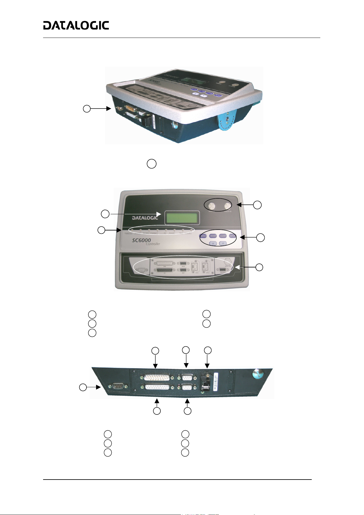
SC6000-1200 STANDARD MODEL
1
Connector Panel
1
SC6000 STANDARD MODEL
Figure A
2
1
Figure B
Power ON and Communication LEDs
1
LCD Display
2
Status LEDs
3
2
3
4
5
Programming Keypad
4
Connector Panel Legend
5
3
4
1
5
Figure C
Ethernet Connector
4
uxiliary Interface Connector
5
Extended I/O Connector
6
Modem Connector
1
Power/Net Connector
2
Main Interface Connector
3
6
1
Page 4
SC6000 STANDARD MODEL
Electrical Connections
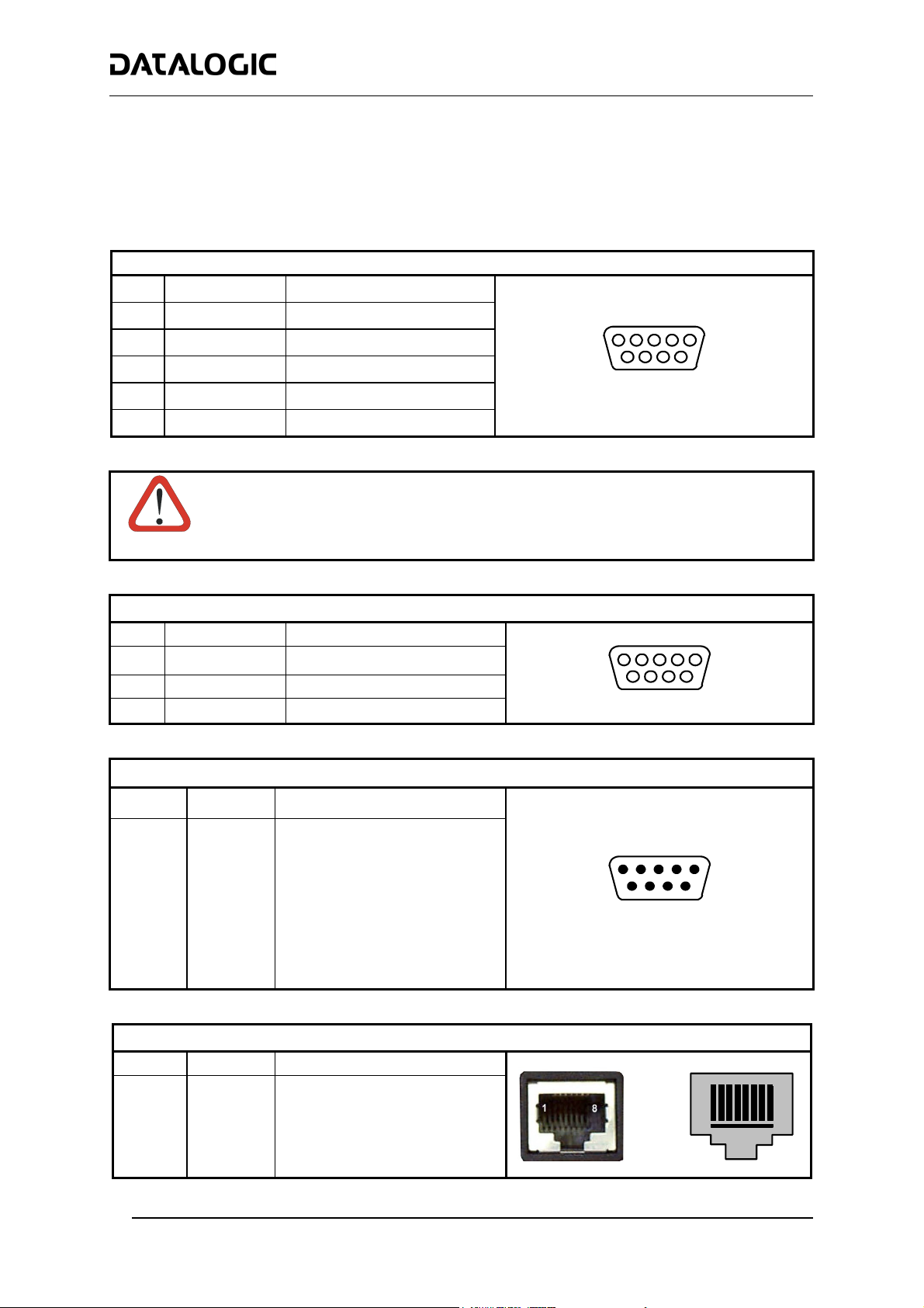
The SC6000 is designed to easily connect to the PWO power supply through two standard accessory cables. All
system cabling is concentrated at the PWO except for some Host connections and the Auxiliary interface for
SC6000 configuration using a laptop PC.
The following connector pinouts are given for reference.
MAIN INTERFACE
Pin RS232 RS485 Full Duplex
2 TX TX485 +
3 RX RX485 +
5
1
5 GND_ISO GND_ISO
7 CTS RX485 -
8 RTS TX485 -
Do not connect GND and GND_ISO to different (external) ground references. GND and
GND_ISO are internally connected through filtering circuitry which can be permanently
damaged if subjected to voltage drops over 0.8 Vdc.
CAUTION
AUXILIARY INTERFACE
Pin Name Function
2 TX Transmit
3 RX Receive
5 GND Ground
MODEM CONNECTOR
Pin Name Function
1 CD Carrier detect
2 RX Receive
3 TX Transmit
4 DTR Data terminal ready
5 GND Ground
6 DSR Data set ready
7 RTS Request to send
8 CTS Clear to send
9 RI Ring indicator
ETHERNET CONNECTOR
Pin Name Function
1 TX + Transmitted data (+)
2 TX - Transmitted data (-)
3 RX + Received data (+)
6 RX - Received data (-)
4, 5, 7, 8 N.C. Not connected
9
9-pin D-sub Female Connector
5
9
9-pin D-sub Female Connector
1
6
9-pin D-sub Male Connector
6
1
6
5
9
1
RJ45 Modular Connector
8
2
Page 5
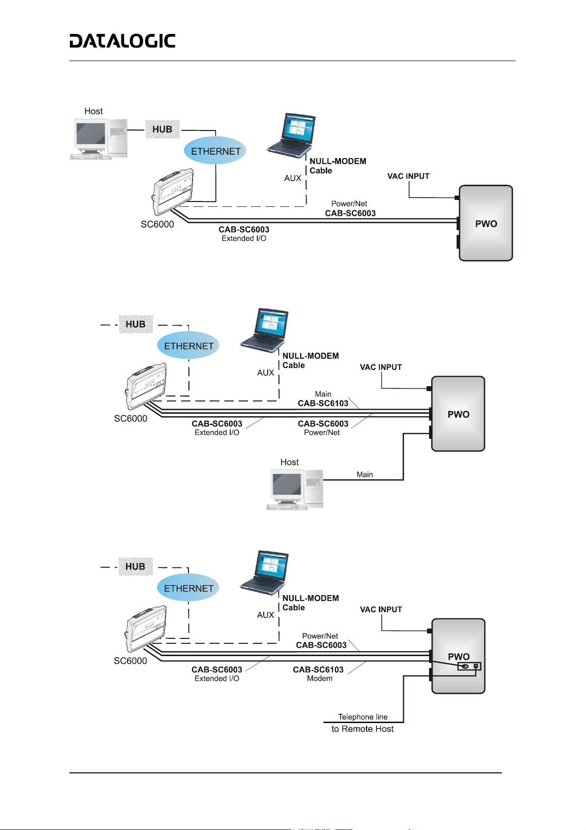
Typical Layouts
SC6000 STANDARD MODEL
Ethernet Connection
Main Connection
Modem Connection
3
Page 6
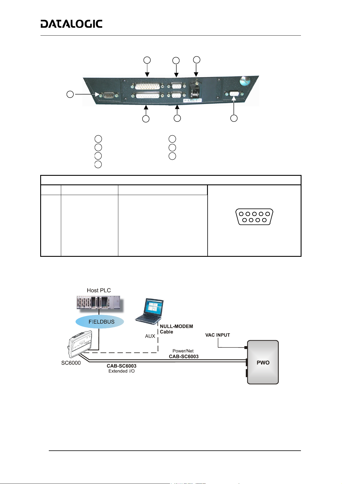
A
SC6000-1211 PROFIBUS MODEL
1
2
SC6000 PROFIBUS MODEL
3
4
Pin Name Function
1 Shield* Shield, protective ground resp.
2 N.C. Not connected
3 B-LINE (RxD/TxD-P) Received/Transmitted data-P
4 CNTR-P** Repeater control signal
5 DGND Data ground (M5V)
6 +5 V Voltage plus (P5V)
7 N.C. Not connected
8 A-LINE (RxD/TxD-N) Received/Transmitted data
9 CNTR-N** Repeater control signal
* signal is optional
** signal is optional; RS485 level
Modem Connector
1
Power/Net Connector
2
Main Interface Connector
3
Ethernet Connector
4
7
SC6000 Profibus Connector Panel
PROFIBUS CONNECTOR
6
Profibus Connector
5
uxiliary Interface Connector
6
Extended I/O Connector
7
5
5
9
9-pin D-sub Female Connector
1
6
Fieldbus Network
4
Page 7
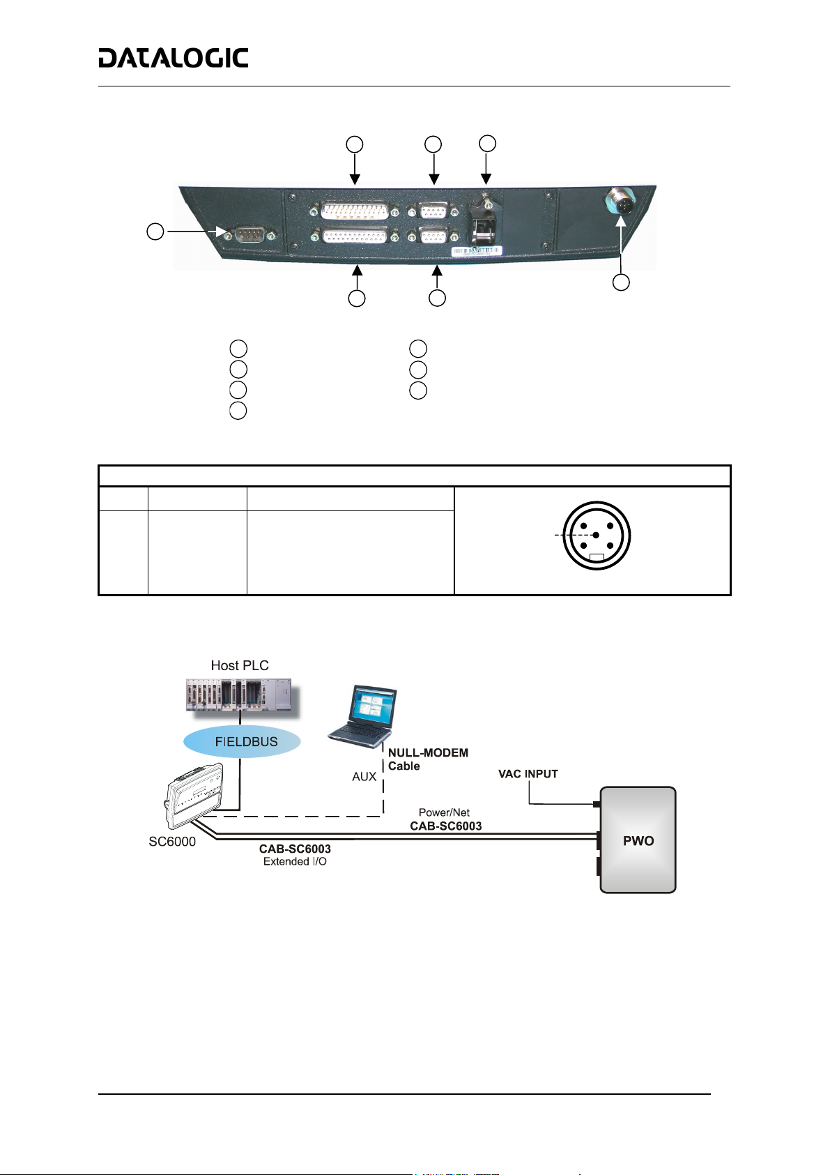
A
SC6000-1215 DEVICENET MODEL
1
2
SC6000 DEVICENET MODEL
3
4
Pin Name Function
2 V+ Supply voltage – positive pin
5 CAN_L CAN bus data line – L
1 SHIELD Shield
4 CAN_H CAN bus data line – H
3 V- Supply voltage – negative pin
Modem Connector
1
Power/Net Connector
2
Main Interface Connector
3
Ethernet Connector
4
7
SC6000 DeviceNet Connector Panel
DEVICENET CONNECTOR
6
DeviceNet Connector
5
uxiliary Interface Connector
6
Extended I/O Connector
7
5-pin male DeviceNet Connector
5
4
5
1
3
2
Fieldbus Network
5
Page 8
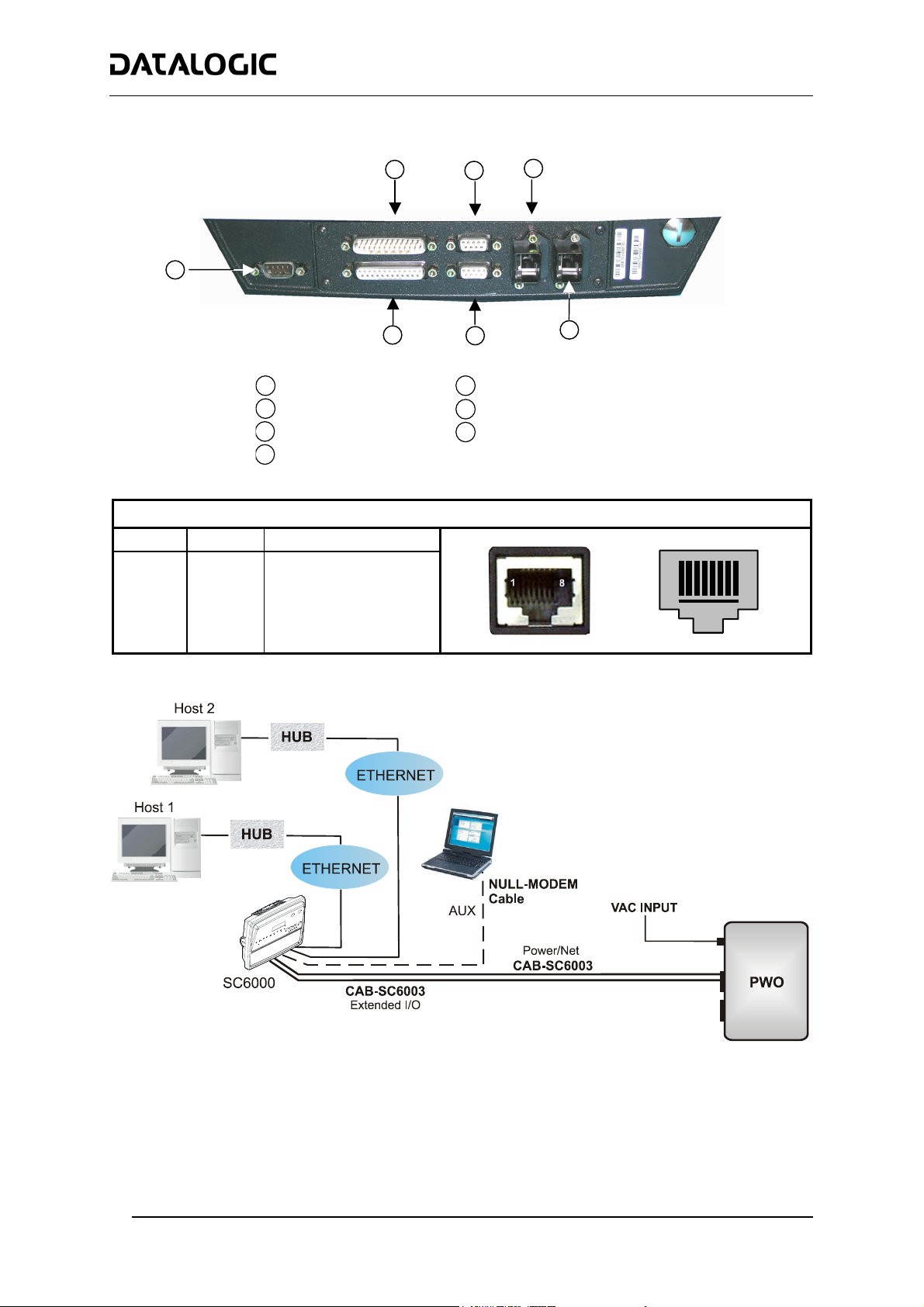
A
SC6000-1230 DUAL ETHERNET MODEL
1
2
3
SC6000 DUAL ETHERNET MODEL
4
Modem Connector
1
Power/Net Connector
2
Main Interface Connector
3
Ethernet Connector
4
Pin Name Function
1 TX + Transmitted data (+)
2 TX - Transmitted data (-)
3 RX + Received data (+)
6 RX - Received data (-)
4, 5, 7, 8 N.C. Not connected
7
SC6000 Dual Ethernet Connector Panel
6
Second Ethernet Connector
5
uxiliary Interface Connector
6
Extended I/O Connector
7
5
ETHERNET CONNECTOR
RJ45 Modular Connector
1
8
Dual Ethernet Connection
6
Page 9
COMMON FEATURES
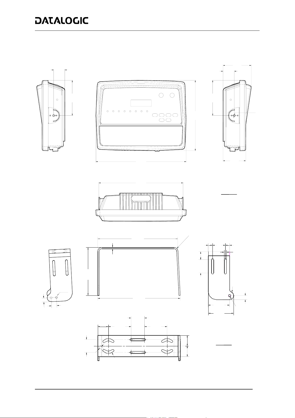
Overall Dimensions
39.7
[1.56]
COMMON FEATURES
99.7
[3.93]
39.7
[1.56]
124.4
[4.90]
248.7
319.5
[12.58]
298
[11.73]
124.4
[4.90]
MØ8
[9.79]
80.2
[3.16]
mm
inch
SC6000 Overall Dimensions
300
[11.80]
5
[0.20]
180
[7.09]
M8
309
[12.17]
0
2
[
0
.
5
9
]
1
9
7
.
0
[
5
]
40
[1.57]85 [3.35]
50
[1.97]
85
[3.35]
5
1
R
]
9
2
5
°
.
0
N
R
[
30
[1.18]
50
[1.97]
16
[0.63]
48
[1.89]
80
[3.15]
95
[3.74]
16
[0.63]
0
1
R
2
°
N
N°6 8
[0.32]
]
9
3
.
0
R
[
N
[
Ø
0
.
3
3
15
[0.59]
°
2
Ø
8
]
48
[1.89]
8
[0.
40
[1.57]
40
33]
N
°
[
2
Ø
2
Ø
.
2
5
2
6
]
[1.57]
ST-222 Bracket Overall Dimensions
mm
inch
7
Page 10

COMMON FEATURES
Mechanical Installation
To mount the SC6000 Controller on the reading station frame proceed as follows:
1 Mount the bracket on the reading station frame: the slots on the bracket will help obtain the best positioning.
When working in environments characterized by strong vibrations, set the screws as close as possible to the
bracket edges, see the figure below.
2 Tighten the ST-222 bracket to the reading station frame using the screws and washers.
Mounting the bracket on the conveyor
3 Position the SC6000 Controller at the top of the bracket: make sure the two large round openings coincide to
the ones located at the edges of the SC6000 Controller.
4 While supporting the SC6000 Controller, rotate the whole device until it is aligned for the best viewing
position, then insert the set pin screw with locking washer until it inserts into one of the small positioning
holes located on the terminal bracket.
Set pin screw
SC6000 Controller Side View with Punched Steel Ring and Relative Set Pin Screw
The specially punched steel ring has been designed to obtain the most precise rotation possible in terms of
angle calibration, steadiness and consequent absence of torque between both sides of device.
8
Page 11
COMMON FEATURES
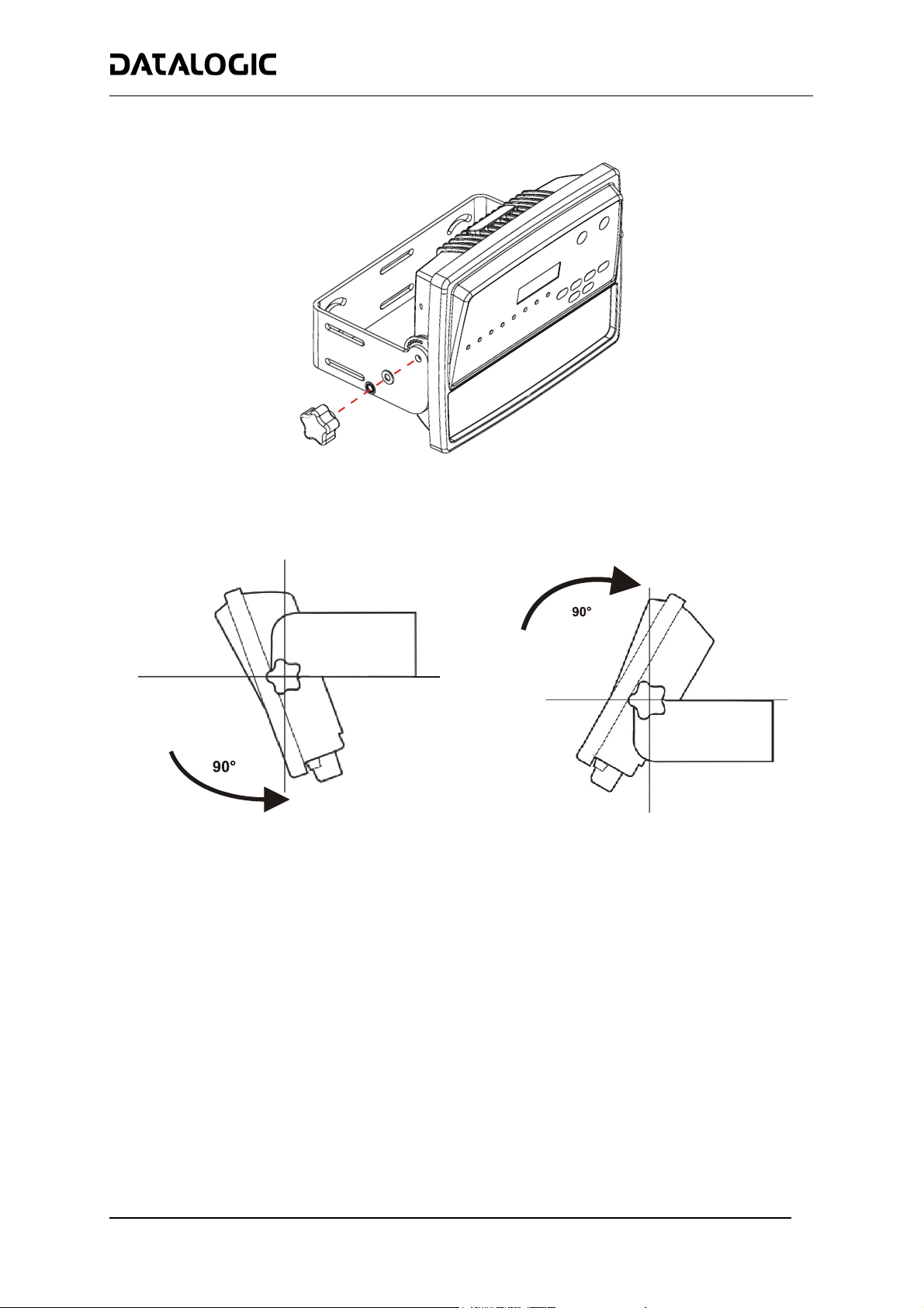
5 Place a locking washer and then a flat washer onto each knob. Tighten the SC6000 Controller to its bracket
by screwing the knobs into their holes - one on each side.
Mounting the SC6000 Controller on the bracket
The SC6000 Controller can rotate on its mounting bracket up to 90° with respect to the mounting bracket position.
See figure below for suggested positions:
Suggested Mounting Positions
9
Page 12
COMMON FEATURES
Electrical Installation
To make electrical connections to your SC6000 controller proceed as follows:
1. Connect the SC6000 controller to the PWO by means of the appropriate accessory cables for your
application.
2. Provide correct and complete system cabling through the PWO according to the signals (Lonworks,
encoder P.S., etc.) necessary for the layout of your application. Refer to the PWO Installation Manual for
details.
Software Installation
To install Genius™, proceed as follows:
1) Turn on the PC that will be used for configuration (Windows 98, NT or XP);
2) Insert the Genius™ CD-ROM;
3) Wait for the CD to autorun and follow the installation procedure.
4) See the Reference Manual for Software Configuration procedures.
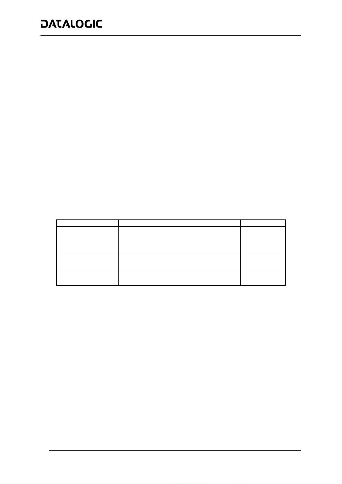
Accessories
The following accessories are used to build up a reading station based on SC6000 (the scanner-related
accessories are not included):
Name Description Part Number
CAB-SC6003 25p cable SC6000 to PWO, 3 m
(for Power/Net & Extended I/O connections)
CAB-SC6103 9p cable SC6000 to PWO, 3 m
(for Main and Modem connections)
CAB-PWO 03 17p cable PWO to PWO, 3 m
(for redundancy)
PWO-480 Power&Connect system, 480W 93ACC1767
Modem INSYS Modem 56K 93A051294
93A051293
93A051294
93A051295
10
Page 13
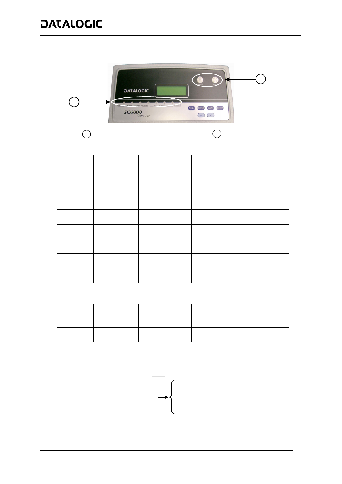
LED Indicators
1
COMMON FEATURES
2
1
Power ON and Communication LEDs
Name Color State Function
Power ON
Tx Data
Rx Data
Ethernet
PS
PS Aux
Tach
Network
Name Color State Function
Warning
Status OK
Green
Green Blinking
Green Blinking
Red
Yellow
Yellow
Yellow
Red
Red
Green
Available Models
Figure 1 - LEDs Description
SYSTEM SIGNAL LEDS
ON
OFF
OFF
OFF
ON
OFF
ON
OFF
ON
OFF
Blinking
OFF
ON
OFF
SYSTEM EVENT STATUS LEDS
ON
OFF
ON
OFF
SC6000 - 1XXX
2
Status LEDs
SC6000 Powered
No Power
Transmitting Data on MAIN
No Data Transmission
Receiving Data on MAIN
No Data Reception
Ethernet Line Connected
No Ethernet Line Connected
Presence Sensor Active
Presence Sensor Not Active
Presence Sensor Active
Presence Sensor Not Active
Encoder Active
Encoder Not Active
Lonworks OK
Lonworks Error
Scanner Cluster Failure
Scanner Cluster OK
Controller Status OK
Controller Failure
200 = Standard
211 = Profibus
215 = DeviceNet
230 = Dual Ethernet
11
Page 14

COMMON FEATURES
Keypad and Display
The SC6000 keypad allows entering a menu to select one of the functions described in the following paragraphs.
STANDARD MODE
Upon startup, the diagnostic mask window is visualized by default. Using the UP and DOWN keys it is possible to
scroll the other windows following this order:
1) Diagnostic Mask Window
2) Reading Performance Window
3) Reading Mask Window
4) I/O Status Window
5) System Info Window
6) Last Codes & Read Mask
7) Alarms
Diagnostic Mask Window (Default Window)
This window illustrates the status of each node (of each scanner of the cluster) according to the following
convention:
" - "
" ? "
" * "
" ! "
" & "
" % "
"Scan A B C"
"Status ***"
"Empty scan cluster"
"No slave expected"
“Energy Saving”
Reading Performance Window
This window displays the following data:
• Number of the processed parcels
• Good Read Rate
• No Read Rate
• Multiple Read Rate
Reading Mask Window
This window indicates the node that performed a reading of the codes enabled on the master.
The following indicators are used:
" * "
" - "
I/O Status Window
This window provides data concerning the conveyor speed and the digital input/output status.
System Info Window
This window provides information about the software release.
Last Codes & Read Mask
This window is available only when enabling the “Last Code & Reading Mask Window” parameter from the
Genius™ configuration program.
The following data are shown:
The node read a barcode enabled on the master.
The node read no barcode.
• Window title
• Last read code
• List of nodes that performed a reading of the codes enabled on the master
• Statistics (No Read rate, Partial Read rate, Multiple Read rate) calculated on the last 100 codes or in
continuous mode depending on the parameter selection.
From the startup the node NID has not been discovered.
At the startup of the system the NID has been discovered but the node does not
answer to the master.
The node status is OK.
The node returns an error code to the diagnostic Laser Off.
The node returns an error code to the diagnostic Motor Off.
The node is in monitor mode.
The specific scanners (indicated by each letter) have been discovered.
The scanner status is ok.
No scanner has been discovered within the cluster.
A scanner not expected by the system configuration has been discovered.
The Energy Saving feature (see Genius™ program Help On-Line) has been
activated.
12
Page 15

COMMON FEATURES
Alarms
This window is available only when enabling the related parameters from the Genius™ configuration program.
It shows four alarms generated by the SC6000 or by the network. All alarms are ordered according to their priority
(failure messages have priority over warning messages).
A failure message causes the Warning LED to be always on, while a warning message causes the LED blinking.
REDUNDANCY MODE
When working in a redundant system, the SC6000 displays different windows according to its redundancy role
(refer to the SC6000 help on-line for further details).
SC6000 Active Controller Window
The SC6000 working as active controller displays the diagnostic mask window, as if it is working in a single
master network.
SC6000 Stand-By Controller Window
This window is displayed on the SC6000 working as stand-by controller. It illustrates the topology redundancy role
of the controller:
• "Protecting/Stand-by" or "Working/Stand-by"
MENU MODE
For security purposes, the menu mode is entered by pressing the ENTER and MENU keys at the same time.
Through this menu, it is possible to perform the following:
• Main Parameter Setting: IP address, Netmask, Gateway address (for all models), Profibus address
(for Profibus models), DeviceNet address (for DeviceNet models), supplementary IP address,
supplementary Netmask, supplementary Gateway address (for Dual Ethernet models).
These parameters may be set through the Genius™ program.
• Date&Time setting;
• DARP™ (Datalogic Automatic Replacement Procedure);
• CASP™ (Cluster AutoSetup Procedure): this procedure allows automatic address assignment to the
scanner cluster nodes. This operation can also be performed by starting up the system while pressing
the SETUP key.
• Last Codes: this window is available only when enabling the “Show Last Code Window” parameter
from the Genius™ configuration program. It displays the last 10 read codes. Each code can be
visualized through the UP and DOWN keys.
Datalogic Automatic Replacement Procedure (DARP™)
When SC6000 is used as a SYNCHRONIZED or MULTIDATA Master (Topology Role parameter)
backup procedure must be performed to automatically manage scanners and SC6000 replacement in case of
failure (DARP™ Restore). Once the system configuration has been completed as described in par. 3.2 of the
SC6000 Reference Manual, launch the DARP™ backup by one of the following methods:
Using Genius:
Click on the DARP™ backup icon in the Device Network area. You will be prompted to select the desired backup
option (complete, all slaves, controller, or each single scanner).
Using the SC6000 keypad:
1. Press the <Ent> and <Menu> keys simultaneously to enter the Menu;
2. Use the <arrow> keys to move within the menu items;
3. In the <System> menu choose <Backup> and select the desired backup option (complete, all scanners,
controller, or each single scanner).
The SC6000 Controller will store the complete system configuration on the Compact Flash card.
, a DARP™
13
Page 16
COMMON FEATURES
If a slave scanner has to be replaced, the corresponding configuration (node address, code configuration,
PackTrack™ configuration, etc.) is automatically downloaded by the SC6000 into the new scanner at the next
system startup.
All replacement scanners must be set to the factory default values BEFORE installing.
NOTE
In case of SC6000 failure, the complete system configuration can be recovered from the damaged SC6000
Compact Flash: by simply installing the old Compact Flash in the new SC6000, the system configuration is
automatically restored and the reading station is ready to start working again.
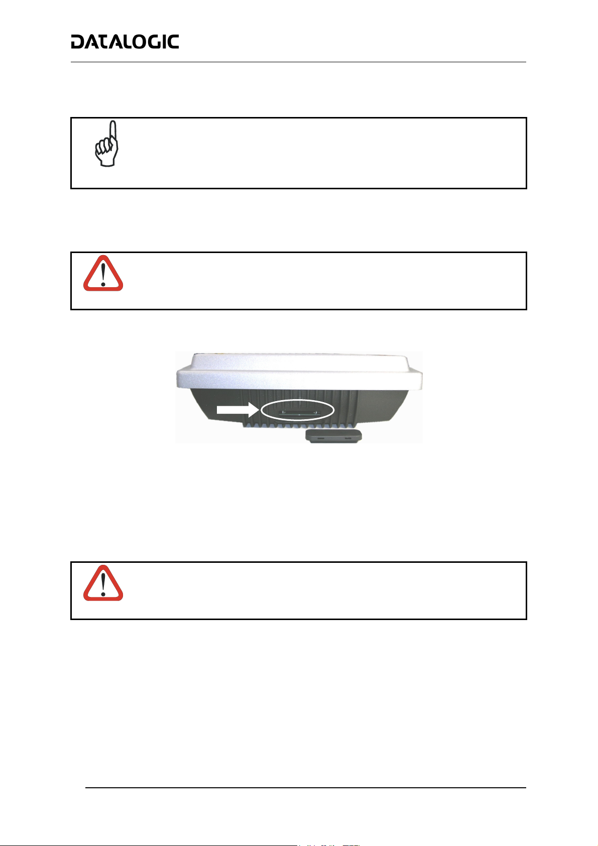
Before removing the Compact Flash card, switch the SC6000 Controller off.
CAUTION
In case of SC6000 failure proceed as follows:
Figure 2 - Removing the Compact Flash
1. Disconnect the device.
2. Remove the rubber cover of the Compact Flash slot using a screwdriver.
3. Remove the Compact Flash.
4. Connect a new SC6000 to the system.
5. Insert the Compact Flash card.
Make sure not to insert the Compact Flash card upside down. Carefully insert it in the
guides, so that it will not fall inside the device. Gently push it into the slot.
CAUTION
6. Start up the system.
The system configuration is automatically restored and the reading station is ready to start working again.
14
Page 17
COMMON FEATURES
Automatic Scanner Replacement (ASR)
When SC6000 is used in a network of DS8100 or DX8200 scanners, (Topology Role parameter = Other; Device
Assignment parameter = Controller Lon Old8K), an ASR backup procedure must be performed to automatically
manage scanners and SC6000 replacement in case of failure (ASR Restore).
In order for the ASR procedure to work, all slave scanners must have been installed
NOTE
Once the system configuration has been completed, launch the ASR backup by one of the following methods:
Using Genius:
Click on the ASR backup item in the Device Menu. You will be prompted to select the desired backup option
(complete, all slaves, controller).
Using the SC6000 keypad:
4. Press the <Ent> and <Menu> keys simultaneously to enter the Menu;
5. Use the <arrow> keys to move within the menu items;
6. In the <System> menu choose <Backup> and select the desired backup option (complete, all scanners,
controller).
The SC6000 Controller will store the complete system configuration on the Compact Flash card.
If a slave scanner has to be replaced, the corresponding configuration (node address, code configuration,
PackTrack™ configuration, etc.) is automatically downloaded by the SC6000 into the new scanner at the next
system startup.
according to the procedure in par. 3.3 of the SC6000 Reference Manual.
All replacement scanners must be set to the factory default values BEFORE installing.
NOTE
If the SC6000 controller replaces an SC8000 controller within the network, (Topology Role
parameter = Other; Device Assignment parameter = Controller Lon SC8000), refer to the
“Replacing SC8000 with SC6000-PWO.pdf” document for details.
NOTE
Compliance
Power Supply
This product is intended to be installed by Qualified Personnel only.
This device is intended to be supplied by either a UL Listed or CSA Certified Power Unit marked 'Class 2' or
'LPS', output rated 15 - 30 V dc , minimum 0.6 A.
WEEE Compliance
15
Page 18
COMMON FEATURES
Technical Features
ELECTRICAL FEATURES
Supply voltage 15 to 30 Vdc
Power consumption 6.5 W typical
9 W Max. (including startup current)
Communication Interfaces
Inputs (optocoupled NPN or PNP) Encoder, PS, PS Aux, 3 polarity insensitive optocoupled inputs
Outputs (optocoupled) 6 optocoupled outputs, 3 relay control inputs
USER INTERFACE
LCD Display 4 lines by 20 characters LCD
Keypad 6 keys
LED indicators Power ON
SOFTWARE FEATURES
Configuration modes
Parameter storage
ENVIRONMENTAL FEATURES
Operating temperature 0° to +50 °C (+32° to +122 °F)
Storage temperature -20° to +70 °C (-4° to +158 °F)
Humidity 90% non condensing
Vibration resistance IEC 68-2-6 test FC
14 mm @ 2 to 10 Hz; 1.5 mm @ 13 to 55 Hz;
2 g @ 70-200 Hz; 2 hours on each axis
Shock resistance IEC 68-2-27 test EA
30 g; 11 ms;
3 shocks on each axis
Protection class IP64*
PHYSICAL FEATURES
Mechanical dimensions 320 x 250 x 90 mm (12.6 x 9.84 x 3.54 in)
Weight 3.3 kg. (7.26 lb)
*with Harting RJ Industrial push pull Ethernet connector.
Main (isolated) Auxiliary Modem
RS232, RS485 full-duplex RS232 RS232
Other
Lonworks 1,25 Mb/s
Ethernet 10 or 100 Mb/s
DeviceNet 125 or 250 Kb/s
Profibus 12 Mb/s
PS
TX data
RX data
Ethernet
Genius™ utility program
Non-volatile extractable FLASH card
PS Aux
TACH
Networks
Controller
Scanners
16
Page 19

DATALOGIC S.p.A., DATALOGIC S.p.A.,
Via Candini, 2 Via Candini, 2
40012 - Lippo di Calderara 40012 - Lippo di Calderara
Bologna - Italy Bologna - Italy
dichiara che dichiara che
declares that the declares that the
déclare que le déclare que le
bescheinigt, daß das Gerät bescheinigt, daß das Gerät
declare que el declare que el
SC6000-XXXXSC6000-XXXX
and all its models
et tous ses modèles
und seine modelle
y todos sus modelos
sono conformi alle Direttive del Consiglio Europeo sottoelencate:
are in conformity with the requirements of the European Council Directives listed below:
sont conformes aux spécifications des Directives de l'Union Européenne ci-dessous:
der nachstehend angeführten Direktiven des Europäischen Rats:
cumple con los requisitos de las Directivas del Consejo Europeo, según la lista siguiente:
89/336/EEC EMC Directive e 92/31/EEC, 93/68/EEC emendamenti successivi
and further amendments
et ses successifs amendements
und späteren Abänderungen
y succesivas enmiendas
Basate sulle legislazioni degli Stati membri in relazione alla compatibilità elettromagnetica ed alla sicurezza dei prodotti.
On the approximation of the laws of Member States relating to electromagnetic compatibility and product safety.
Basées sur la législation des Etats membres relative à la compatibilité électromagnétique et à la sécurité des produits.
Über die Annäherung der Gesetze der Mitgliedsstaaten in bezug auf elektromagnetische Verträglichkeit und Produktsicherheit
entsprechen.
Basado en la aproximación de las leyes de los Países Miembros respecto a la compatibilidad electromagnética y las Medidas
de seguridad relativas al producto.
Questa dichiarazione è basata sulla conformità dei prodotti alle norme seguenti:
This declaration is based upon compliance of the products to the following standards:
Cette déclaration repose sur la conformité des produits aux normes suivantes:
Diese Erklärung basiert darauf, daß das Produkt den folgenden Normen entspricht:
Esta declaración se basa en el cumplimiento de los productos con las siguientes normas:
EN 55022 (Class A ITE), August 1994:
Amendment A1 (Class A ITE), October 2000:
EN 61000-6-2, October 2001: E
Universal Controller e tutti i suoi modelli
IMITS AND METHODS OF MEASUREMENTS OF RADIO DISTURBANCE
L
CHARACTERISTICS OF INFORMATION TECHNOLOGY EQUIPMENT
LECTROMAGNETIC COMPATIBILITY (EMC)
P
ART 6-2: GENERIC STANDARDS - IMMUNITY FOR INDUSTRIAL ENVIRONMENTS
05
Lippo di Calderara, 08.09.05
Ruggero Cacioppo
Quality Assurance Laboratory Manager
821001133 (Rev. D)
 Loading...