

Datalogic QLM700 Installation Manual

QLM700
INSTALLATION MANUAL
Figure A
1 Power In Connector and LED 6 Profinet IO Port 2 Connector and LED
2 ID-NET Connector and LED 7 Auxiliary Port Connector
3 Trigger Connector and LED 8 IP Address Selectors (last octet)
4 I/O Connector and LED 9 Reading Device Connector
5 Profinet IO Port 1 Connector and LED 10 Mounting slots (6)
821002140
1
9
7
3
4
8
10
2
5
6

QLM700 INSTALLATION MANUAL
2
UPDATES AVAILABILITY
UK/US
The latest documentation updates for this product are available on Internet.
Log on to: www.automation.datalogic.com
I
Su Internet sono disponibili le versioni aggiornate di documentazione di questo prodotto.
Collegarsi a: www.automation.datalogic.com
F
Les versions mises à jour de documentation de ce produit sont disponibles sur Internet.
Cliquez sur : www.automation.datalogic.com
D
Im Internet finden Sie die aktuellsten Versionen der Dokumentation von diesem Produkt.
Adresse : www.automation.datalogic.com
E
En Internet están disponibles las versiones actualizadas de la documentación de este
producto.
Dirección Internet : www.automation.datalogic.com
SERVICES AND SUPPORT
Datalogic provides several services as well as technical support through its website. Log on to
www.automation.datalogic.com and click on the links indicated for further information including:
PRODUCTS
Search through the links to arrive at your product page which describes specific Info, Features,
Applications, Models, Accessories, and Downloads including the Genius™
utility program, which
allows device configuration using a PC. It provides RS232 and Ethernet interface configuration.
SERVICE
- Overview
- Warranty Extensions and Maintenance Agreements
- Sales Network
- Listing of Subsidiaries, Repair Centers, Partners
- Helpdesk
- Material Return Authorization
LEGAL NOTICES
© 2012 Datalogic Automation S.r.l. ALL RIGHTS RESERVED. Protected to the fullest extent under
U.S. and international laws. Copying, or altering of this document is prohibited without express written
consent from Datalogic Automation S.r.l.
Datalogic and the Datalogic logo are registered trademarks of Datalogic S.p.A. in many countries,
including the U.S.A. and the E.U.
ID-NET, and Genius are trademarks of Datalogic Automation S.r.l. All other brand and product names
mentioned herein are for identification purposes only and may be trademarks or registered trademarks
of their respective owners.
Datalogic shall not be liable for technical or editorial errors or omissions contained herein, nor for
incidental or consequential damages resulting from the use of this material.

QLM700 INSTALLATION MANUAL
3
DESCRIPTION
The QLM700 Profinet IO Gateway is an active connection module which can be used in
Standalone or ID-NET™ Master Multidata, or Master Synchronized layouts. It provides a fast
and efficient way to cable both an Profinet IO network and an ID-NET™ network using
standard cables.
It provides separate M12 connectors for Power Supply, Profinet Communication, ID-NET™
Network, External Trigger, Digital I/O and Aux RS232 Communication for configuration of the
reading device.
The QLM700 Gateway provides an easy way to connect many Datalogic reading devices to
any PLC with Profinet IO support. It allows Profinet IO real-time communication with bus
topologies, and due to its two Profinet ports, it eliminates the need for expensive external
switches.
Host communication is provided through the integrated Profinet IO circuitry which connects
internally to the reader's Main serial interface (RS232).
ID-NET™ network and power supply signals are provided to the next connected device (IDNET™ Slave), by means of a dedicated M12 connector. However there is not a second
ID-NET™ network connector for bus propagation and therefore the QLM700 cannot be used
as an ID-NET™ Slave.
The reading device is connected to the QLM700 through a standard 25-pin D-sub connector.
Three rotary switches allow easy manual Network Addressing selection.
The following accessories make system cabling easy:
CBL-1487 connector or CS-A2-02-G-xx cable, to build the Power Supply connection.
FMC600 connector, to build the I/O connections.
CAB-AUX03 cable, to connect the Gateway to a PC to configure the connected reading
device.
CBL-1480-xx cable, to build the ID-NET network connections.
If necessary, commercial cables are available for trigger connections to a PNP photocell (see
TRG Connector paragraph).
QLM700 has integrated on-board backup memory and therefore supports Backup and
Restore procedures for the connected device and relative ID-NET™ network (if used). See
the device's Backup and Restore procedure in the Help On Line.
For the 2KN-4K Family Scanners, Backup and Restore can also be performed using
programming barcodes, see the Setup Procedure Using Programming Barcodes document
on the reader's CD-ROM.
NOTE
For full compatibility with QLM700, the 2KN-4K Family Scanner must have
software package 007_3 or later.
QLM700 INSTALLATION MANUAL
4
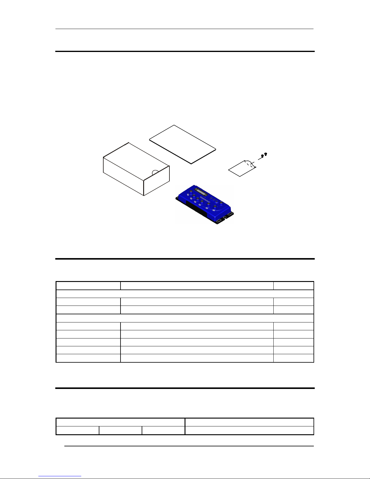
PACKAGE CONTENTS
Verify that the QLM700 and all the parts supplied with the equipment are present and intact
when opening the packaging; the list of parts includes:
QLM700 Gateway
This Installation Manual
Mounting screws and washers (2)
M12 protection caps (5) pre-mounted
Figure 1 - Package Contents
ACCESSORIES
The following accessories are available on request for the QLM700:
Name Description Part Number
Field Mountable Connectors
CBL-1487 PWR-IN CONNECTOR M12 5P F. A-Coded 93A050045
FMC600 QLM-I/O CONNECTOR M12 8P M. A-Coded 93ACC0040
Cables
CS-A2-02-G-03 PWR-IN Cable M12/5P FEMALE 90°/4 WIRES 3M 95A251360
CS-A2-02-G-10 PWR-IN Cable M12/5P FEMALE 90°/4 WIRES 10M 95A251260
CAB-AUX03 SERIAL CABLE M12/3P MALE/DB9 3M 93A051385
CBL-1480-01 ID-NET Out/In M12/5P MALE/FEMALE 1M IDNET 93A050049
CBL-1480-02 ID-NET Out/In M12/5P MALE/FEMALE 2M IDNET 93A050050
SUPPORTED READING DEVICES
The QLM700 can be directly connected to all of the following readers through the 25-pin
connector illustrated in Figure A.
Linear Scanners 2D Readers
DS2100N DS2400N DS4800 (future release)

QLM700 INSTALLATION MANUAL
5
MECHANICAL INSTALLATION
QLM700 can be mounted to various surfaces using the two M5x20 screw and washers
included in the package:
The M5x20 screws can be used to mount the QLM700 to metallic/plastic surfaces already
prepared with M5 threaded holes.
QLM700 can also be mounted to a Bosch Frame using the two M5x20 screws included in
the package, plus two specific commercial T-nuts (for example the Bosch Rexroth T-nut 10
M5, cod. 3 842 530 283).
Mounting to other surfaces, such as concrete walls or metallic panels, requires
appropriate user-supplied parts (screws, screw anchors, nuts, etc).
The diagram below gives the overall dimensions of the QLM700 and shows the mounting
through-holes.
39
[1.55]
9.5
[0.37]
5.5
[0.22]
n° 2
5.5
[0.22]
n° 4
188
[7.40]
200
[7.88]
53.5
[2.11]
81
[3.18]
= =
= =
Figure 2 - Overall Dimensions
Mounting
Slots (6)
mm
[in]
 Loading...