

Page 1

MX-E Series Hardware Guide
for Processor and Cameras
Revision Date: July 19, 2018
Page 2

Compliance
Datalogic S.r.l. makes no representations or warranties for merchantability or fitness for any particular purpose, regarding
Datalogic’s software or hardware. Datalogic S.r.l. shall not be liable for errors contained herein or for incidental or consequential damages in connection with the furnishing, performance, or use of this publication or its contents.
Datalogic S.r.l. reserves the right to revise this publication from time to time and to make changes in the content hereof
without obligation to notify any person of such revision or changes.
Datalogic S.r.l.
Via S. Vitalino 13
40012 Calderara di Reno - Italy
www.datalogic.com
©2015 - 2018 Datalogic S.p.A. and/or its affiliates
part of this documentation may be reproduced, stored in or introduced into a retrieval system, or transmitted in any form
or by any means, or for any purpose, without the express written permission of Datalogic S.p.A. and/or its affiliates.
Datalogic and the Datalogic logo are registered trademarks of Datalogic S.p.A. in many countries, including the U.S. and
the E.U. Impact, P-Series, MX-U Series, MX-E Series, Vision Program Manager (VPM), Pinpoint Pattern Find, and
Control Panel Manager (CPM) are trademarks of Datalogic S.p.A. and/or its affiliates. All other trademarks and brands
are property of their respective owners.
All rights reserved. Without limiting the rights under copyright, no
CE Compliance
CE marking states the compliance of the product with essential requirements listed in the applicable European directive.
Since the directives and applicable standards are subject to continuous updates, and since Datalogic promptly adopts these
updates, therefore the EU declaration of conformity is a living document. The EU declaration of conformity is available
for competent authorities and customers through Datalogic commercial reference contacts. Since April 20th, 2016 the
main European directives applicable to Datalogic products require inclusion of an adequate analysis and assessment of the
risk(s). This evaluation was carried out in relation to the applicable points of the standards listed in the Declaration of
Conformity. Datalogic S.r.l. products are mainly designed for integration purposes into more complex systems. For this
reason it is under the responsibility of the system integrator to do a new risk assessment regarding the final installation.
Warning
This is a Class A product. In a domestic environment this product may cause radio interference in which case the user may
be required to take adequate measures.
EAC Compliance
Customs Union
The CU Conformity certification has been achieved; this allows the Product to bear the Eurasian mark of conformity.
Support Through the Website
Datalogic provides several services as well as technical support through its website. Log on to www.datalogic.com and
click on the SUPPORT link which gives you access to:
• Downloads by selecting your product model from the dropdown list in the Search by Product field for specific Data
Sheets, Manuals, Software & Utilities, and Drawings;
Page 3

• Repair Program for On-Line Return Material Authorizations (RMAs) plus Repair Center contact information;
• Customer Service containing details about Maintenance Agreements;
• Technical Support through email or phone.
Page 4

Page 5

MX-E Series Hardware Guide Table of Contents
TABLE OF CONTENTS
Chapter 1: When Your System Arrives
System Factory Setup........................................................................................... 1
Hardware Components .................................................................................. 2
Safety Precautions......................................................................................... 2
Turning Off the System .................................................................................. 3
Processor Specifications....................................................................................... 4
Setting Up the System .......................................................................................... 5
Top Panel Connections.................................................................................. 7
Front Panel Connections ............................................................................... 8
Rear View ...................................................................................................... 9
Status Lights ....................................................................................................... 10
Preventive Maintenance...................................................................................... 11
Before You Call............................................................................................ 11
Chapter 2: Basic Hardware Components
Processor Views and Dimensions....................................................................... 13
Processor Installation.......................................................................................... 15
Safety Instructions ....................................................................................... 15
Flat Surface Mounting.................................................................................. 15
Power Supply Connection................................................................................... 17
Grounding Concepts .................................................................................... 18
USB Hardware Key ............................................................................................. 19
CFast Card.......................................................................................................... 20
Battery................................................................................................................. 21
Chapter 3: M-Series and E-Series Cameras
Introduction ......................................................................................................... 23
Safety Precautions .............................................................................................. 23
M1xx and E1xx Camera Dimensions .................................................................. 25
M2xx Camera Dimensions........................................................................... 26
M3xx Camera Dimensions........................................................................... 27
M565/M570/M575/M580 Camera Dimensions ............................................ 28
M6xx Camera Dimensions........................................................................... 29
Mounting the Camera.......................................................................................... 29
Connecting the Camera ...................................................................................... 32
M1xx and E1xx Camera Connection ........................................................... 32
M2xx and M3xx Camera Connection........................................................... 36
M565/M570/M575/M580 Camera Connection ............................................. 39
M6xx Camera Connection ........................................................................... 44
Third-party Cameras ........................................................................................... 46
JAI Cameras ................................................................................................ 47
Basler Cameras ........................................................................................... 55
Basler Line Scan Camera ............................................................................ 60
Basler Line Scan Camera Connection......................................................... 60
Baumer Cameras......................................................................................... 65
Smartek Cameras ........................................................................................ 66
SVS-Vistek Cameras (non-IP67 rated) ........................................................ 70
SVS-Vistek Cameras (IP67 rated) ............................................................... 73
Camera Specifications ........................................................................................ 75
E-Series ....................................................................................................... 75
E1xx, E1xxC ................................................................................................ 75
E101, E101C................................................................................................ 75
E151, E151C................................................................................................ 76
E181, E181C................................................................................................ 77
E182, E182C................................................................................................ 78
E193, E193C................................................................................................ 79
E198, E198C................................................................................................ 80
M-Series....................................................................................................... 81
i Datalogic S.r.l.
Page 6

Table of Contents MX-E Series Hardware Guide
M1xx, M1xxC ............................................................................................... 81
M110, M110C............................................................................................... 81
M150, M150C............................................................................................... 82
M180, M180C............................................................................................... 83
M190, M190C............................................................................................... 84
M195, M195C............................................................................................... 85
M197, M197C............................................................................................... 86
M2xx, M2xx-RA, M2xxC, M2xxC-RA ........................................................... 87
M205 line...................................................................................................... 87
M210 line...................................................................................................... 88
M230 line...................................................................................................... 89
M270 line...................................................................................................... 90
M290 line...................................................................................................... 91
M565/M570/M575/M580 Camera ................................................................ 92
M565 camera ............................................................................................... 92
M570 camera ............................................................................................... 93
M575 camera ............................................................................................... 93
M580 camera ............................................................................................... 93
M6xx, M6xxC ............................................................................................... 94
M610 and M610C......................................................................................... 95
M650 and M650C......................................................................................... 96
M680 and M680C......................................................................................... 97
Chapter 4: Processor I/O
Processor I/O Connection ................................................................................... 99
Processor Inputs ............................................................................................... 102
Input Wiring ................................................................................................ 102
Processor Outputs............................................................................................. 104
Output Wiring ............................................................................................. 105
Chapter 5: Cable Reference
Processor Cables .............................................................................................. 107
Ethernet...................................................................................................... 107
Input/Output ............................................................................................... 107
Power Supply ............................................................................................. 107
Serial Port .................................................................................................. 108
Monitor/Panel ............................................................................................. 108
Display Port................................................................................................ 108
USB Ports .................................................................................................. 108
Camera Cable ................................................................................................... 109
M1xx and E1xx........................................................................................... 109
ii Datalogic S.r.l.
Page 7

CHAPTER 1
When Your System Arrives
Thank you for purchasing an MX-E Series embedded machine vision system (MX-E Series Processor). Please read the
instructions in this document before starting your system setup.
This manual explains the various parts of the MX-E Series system hardware, including the system inputs and outputs
available to integrate your system into a production line. This manual covers the entire line of MX-E Series processors.
Sections that apply to a specific model number are indicated.
When your system arrives, check the shipping cartons for wrinkled or damaged corners, holes through the cardboard, or
other signs of rough handling or abuse. If you find any signs of damage, ask the delivery service to make a note on the
delivery receipt describing the damage.
Carefully remove the system unit, cameras, cabling, and accessories from the shipping package. Place all equipment you
unpack on a table and inspect each item. Report any damage to the carrier immediately. Save all packing materials so you
can repack the shipment in case you need to move or ship it.
Temperature precautions: If your system arrives in very cold or hot weather, allow all the equipment to reach room temperature before plugging it in. Exposing a cold device to a warm room causes condensation that could damage the system
if power is applied too soon. If condensation forms, wait for it to dry completely.
System Factory Setup
Before we shipped your MX-E Series vision system, we ran the installation and setup program and specified a default
software and hardware configuration. See page 5 for more information about setting up the hardware. Refer to the Impact
Reference Guide for software configuration information.
IMPORTANT NOTE:
A USB Hardware key is ordered and shipped separately from the processor. It must be present in the USB port labeled
USB5 on the processor front before the processor is powered on. (See “Front Panel Connections” on page 8 and “USB
Hardware Key” on page 19.)
Processor Front View
A USB Hardware key is ordered and
shipped separately from the processor. It
must be present in the USB port labeled
USB5 on the processor front before the
processor is powered on.
1 Datalogic S.r.l.
Page 8

Hardware Components MX-E Series Hardware Guide
Hardware Components
The major hardware components of the system are the MX-E Series Processor, camera, and cables.
NOTE: All descriptions and specifications apply to all models unless otherwise noted.
• MX-E20-2-P-1, 2-camera capable, PNP outputs
• MX-E20-2-N-1, 2-camera capable, NPN outputs
• MX-E40-2-P-1, 2-camera capable, PNP outputs
• MX-E40-2-N-1, 2-camera capable, NPN outputs
• MX-E40-4-P-1, 4-camera capable, PNP outputs
• MX-E40-4-N-1, 4-camera capable, NPN outputs
• MX-E80-2-P-1, 2-camera capable, PNP outputs
• MX-E80-2-N-1, 2-camera capable, NPN outputs
• MX-E80-4-P-1, 4-camera capable, PNP outputs
• MX-E80-4-N-1, 4-camera capable, NPN outputs
• For details about MX-E Series cables, see “Processor Cables” on page 107.
• For details about MX-E Series cameras, see “Camera Specifications” on page 75.
Safety Precautions
Warning: There are no user-serviceable parts inside the hardware. To avoid electrical shock, never open the case.
Modifying or tampering with internal components will void the product warranty.
Attention: Il n'y a aucune pièce réparable par l'utilisateur à l'intérieur du dispositif. Pour éviter un choc électrique,
n'ouvrez jamais le cas. Modification ou manipulation des composants internes annulera la garantie du produit.
1. Read all of the following instructions before setting up your system. Save this document for later use.
2. Follow all warnings and instructions in this manual and in other user guides shipped with your hardware components.
3. To avoid damage to the vision system and its components, never plug in or unplug a cable when the power is on.
Always shut down the processor and turn off the power supply before you make cable changes (see “Turning Off
the System” on page 3).
Datalogic S.r.l. 2
Page 9
MX-E Series Hardware Guide Turning Off the System
4. Never use the system if a power cable has been damaged. Do not allow anything to rest on a power cable and keep
them away from traffic.
5. The air inlets and exhausts on the unit are for ventilation. Do not block or cover these openings or insert anything
into these openings.
6. Do not expose the vision system to moisture, rain, or snow, and do not use it near water. If a component gets wet
unplug it immediately.
7. To avoid injury, never open the case. Modifying or tampering with internal components will void the product warranty.
Service Personnel Only - Caution: Risk of explosion if battery is replaced by an incorrect type. Dispose of used
batteries according to battery maker’s instructions.
Turning Off the System
Warning: Turning off the processor power before stopping VPM and the Windows operating system can damage
the processor and corrupt vision programs and other system files.
Processor Turn Off Procedure
1. If any cameras are online, turn them offline.
2. Close all open vision programs.
3. Disconnect VPM from any connected cameras.
4. Close VPM.
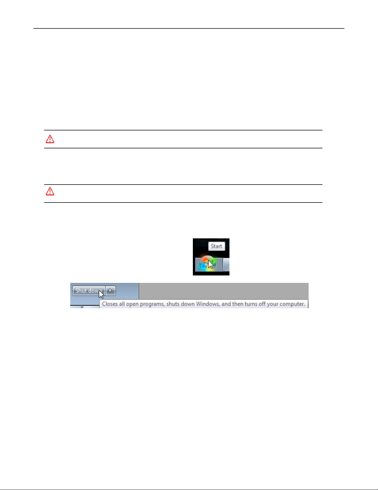
5. Click the Windows Start menu.
6. Click Shut down.
7. Wait approximately 30 seconds for the disk access and other processor functions to stop.
8. If the processor does not power off automatically, press and release the power button on the front of the processor
(see “Front Panel Connections” on page 8).
3 Datalogic S.r.l..
Page 10

Processor Specifications MX-E Series Hardware Guide
Processor Specifications
This section lists the general operating specifications for all MX-E Series Processors as well as individual processor
model hardware. Only Datalogic GigE cameras will operate with MX-E Series Processors. USB cameras cannot be used.
Each of the M-Series cameras has different operating specifications. See “M-Series and E-Series Cameras” on page 23 for
details.
Technical Data
Supply voltage (Vs) 24 VDC ±10%
Nominal Current Draw 5.5 A at 24 VDC
Digital Inputs 16 opto-isolated
Input Current On: 2.0 mA or more
Off: 0.16 mA or less
Digital Outputs 16 opto-isolated current sinking (NPN) or sourcing (PNP)
Output Voltage 35 VDC (max)
Output Current 100 mA max per output
Output saturation voltage < 1V
Dimensions 5.12 w x 10.63 h x 10.03 d (in)
130 w x 270 h x 255 d (mm)
Temperature Operating: 0° to +55° C (+32° to +131° F)
Storage: -20° to +60° C (-4° to +140° F)
Relative Humidity (30 °C) Operating: 10% to 90% (non-condensing)
Storage: 5% to 95% (non-condensing)
Vibrations
(EN60068-2-6)
Shock resistance
(EN60068-2-27)
Housing material Galvanized plate, plastic
Mechanical protection (EN
60529)
Weight 4.52 lb. (2.05 kg)
Minimum Impact Software
Version Required
CPU MX-E20: Intel® Celeron 1047UE 1.4 Ghz – dual core
2 to 8 Hz: 1.75 mm amplitude /
9 to 200 Hz: 0.5 g
11 MS (15 G)
IP20
11.5.0
MX-E40: Intel® Celeron G3900E 2.4 Ghz – dual core
MX-E80: Intel® QM170 i5 6440EQ 2.7 Ghz – quad core
System Memory MX-E20: 4 GB DDR3 RAM
MX-E40: 8 GB DDR3 RAM
MX-E80: 16 GB DDR3 RAM
Datalogic S.r.l. 4
Page 11

MX-E Series Hardware Guide Setting Up the System
Technical Data
Storage MX-E20 and MX-E40: 60 GB SATA SSD (MLC)
MX-E80: 128 GB SATA SSD (MLC)
Graphics Intel® HD (1920x1200 resolution) - DVI
PCIe 1 x PCIe x8
Camera Interface MX-E20: 2 x GigE Ethernet ports (PoE capable; enable/disable in VPM-
Settings)
MX-E40 and MX-E80: 2 or 4 x GigE Ethernet ports (PoE capable; enable/
disable in VPM-Settings)
Keyboard/Mouse
USB Ports
Serial Communication 1 x RS-232 Serial port
Communication Connectivity Supports Ethernet/IP, Modbus, TCP, PROFINET, and OPC
Network interface 2 x LAN ports 10/100/1000 Mbps Base-T
4 x USB 3.0 ports
MX-E40 and MX-E80: optional USB 2.0 port
Cable 606-0677-xx
Setting Up the System
WARNING: To avoid damage to your unit, never plug in or unplug any cables when the unit power is on. Always shut
down the processor and turn off the power supply first before making any cable changes (see “Turning Off the System” on
page 3).
NOTE: When a new processor is powered on the first time, a monitor, keyboard, and mouse must be connected to the processor to approve the license agreement.
1. Familiarize yourself with the major system components as shown in this manual.
2. Unpack and check all the equipment.
3. Mount the MX-E Series Processor and power supply in their desired positions as indicated in the mounting instructions (see “Processor Installation” on page 15). Make sure all vents have at least 1.5 inches (38.1 mm) of clearance
for sufficient ventilation.
4. Connect the I/O cable, optional monitor, and optional keyboard to the MX-E Series Processor. Connect the I/O
cable to the terminal block. When a new processor is powered on the first time, a monitor, keyboard, and mouse
must be connected to the processor to approve the license agreement.
5. Attach the appropriate lens for the application to the camera. Mount the MX-E Series camera, lighting, and
optional power supply. See “Mounting the Camera” on page 29.
NOTE: Do not leave the camera imager uncovered. When you remove the lens cap, you must replace it with a lens.
6. Connect the camera to a Processor GigE port using a Datalogic cable. See “Top Panel Connections” on page 7.
7. You are ready to wire the hardware. See “Processor I/O” on page 99 for details about input/output schematics for
your MX-E Series system. Wiring specifications for all cables are described in “Cable Reference” on page 107.
5 Datalogic S.r.l..
Page 12

Setting Up the System MX-E Series Hardware Guide
8. Wire the MX-E Series camera’s strobe and trigger connections to the camera’s terminal blocks. See “Connecting
the Camera” on page 32.
9. Wire the MX-E Series Processor power connector to the optional power supply. Wire AC power to the power supply. Connect the power supply plug to the processor connector. See “Power Supply Connection” on page 17.
10.Connect the cables from the MX-E Series terminal blocks to their cameras.
11.IMPORTANT: A USB Hardware key is ordered and shipped separately from the processor. It must be present in
the USB port labeled USB5 on the processor front before the processor is powered on. (See “System Factory
Setup” on page 1 and “USB Hardware Key” on page 19.)
12.Plug the power supplies into an appropriate grounded power source. To protect your system, we recommend using
a surge protector.
13.Turn on the MX-E Series Processor power switch. Turn on the camera power supply.
NOTE: Default network IP addresses were assigned to the MX-E Series Processor and Cameras at the factory. You will
probably not need to change them unless there is a conflict with other devices on your network.
14.Start the Impact Software program Vision Program Manager and click on the Settings tab. Check your camera and
lighting setup, calibrate the camera, configure your inspection parameters, then put the camera online. For more
information about using Impact software, refer to the Impact Reference Guide.
If your system does not work when you are finished with the setup, review the instructions and diagrams to make sure you
made all connections properly.
Please note that Datalogic cannot guarantee the performance of MX-E Series systems which have additional software
installed on them, including, but not limited to, anti-virus and firewall software. Datalogic recommends that MX-E Series
systems remain disconnected from networks that access the Internet in order to minimize security risks. Datalogic will
attempt to support systems with antivirus software installed, but we cannot guarantee system performance.
Datalogic S.r.l. 6
Page 13
MX-E Series Hardware Guide Top Panel Connections
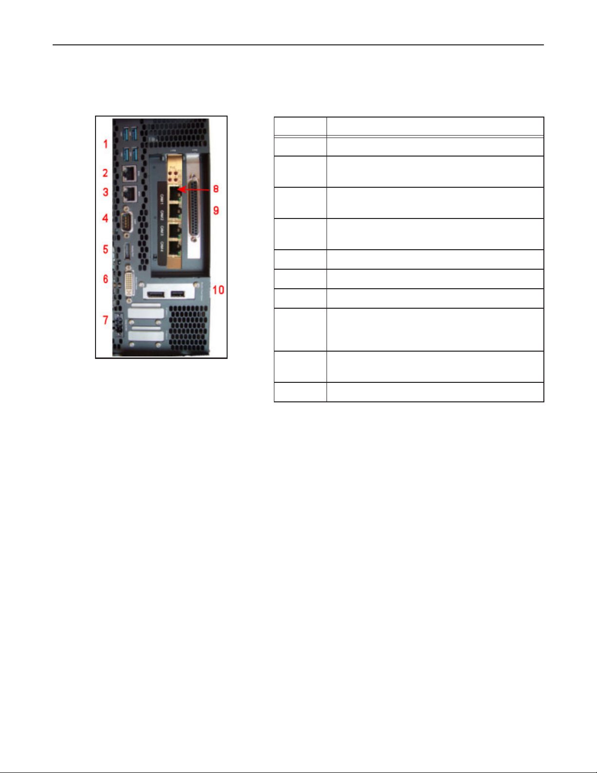
Top Panel Connections
This illustration shows the connections on the Processor’s top panel.
Symbol Function
1 USB 3.0 (x 4)
2 ETH2 - Ethernet 2 (See “Status Lights” on
page 10)
3 ETH1 - Ethernet 1 (See “Status Lights” on
page 10)
4 RS232 Serial Port (COM 1) - See “Serial Port”
on page 108
5 Display Port connection
6 Monitor/Panel connection for smart monitor
7 Supply Voltage
8 Camera Connectors Cam1 through Cam4
Cable 606-0677-xx (Also see “Status Lights” on
page 10)
9 37-pin D-Sub Digital I/O (See “Processor I/O
Connection” on page 99)
10 (optional) USB 2.0 and Display Port
7 Datalogic S.r.l..
Page 14
Front Panel Connections MX-E Series Hardware Guide
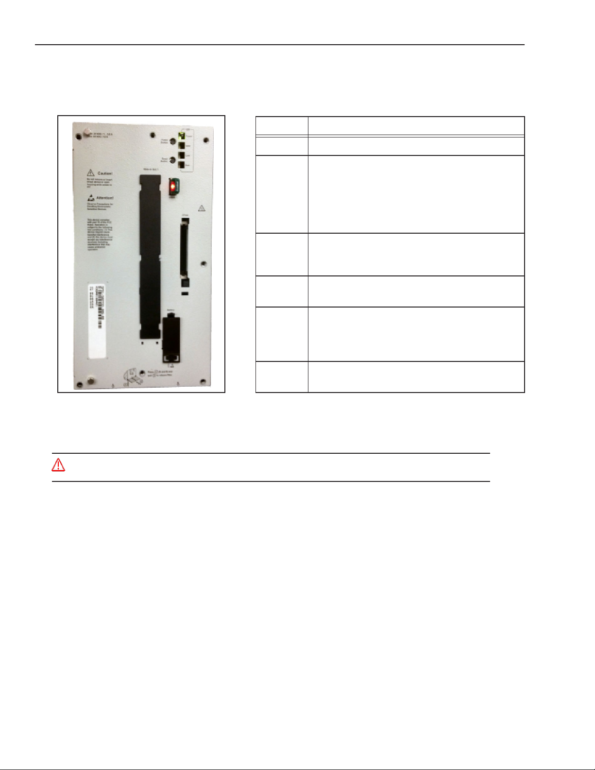
Front Panel Connections
This illustration shows the connections on the Processor’s front panel.
Symbol Function
B
A
C
D
E
F
A Status Lights (see “Status Lights” on page 10)
B Power Button: Press and release to turn the unit
on or off. If the unit is on, press and release to
shut down the OS and switch off the unit (see
“Turning Off the System” on page 3).
Press and hold to switch off without OS shut
down. (Warning: Data could be lost.)
C Reset Button: Resets the processor which trig-
gers a hardware and PCI reset. The processor
is restarted. (Warning: Data could be lost.)
D USB 2.0 Port for USB Hardware key only. See
“USB Hardware Key” on page 19.
E CFast Slot. A CFast card can be used for
extended storage. Note: Do NOT insert or
remove the card while the unit is powered on.
(See “CFast Card” on page 20)
F Battery Compartment (see “Battery” on
page 21)
Service Personnel Only - Caution: Risk of explosion if battery is replaced by an incorrect type. Dispose of used
batteries according to battery maker’s instructions.
Datalogic S.r.l. 8
Page 15

MX-E Series Hardware Guide Rear View
Rear View
This illustration shows the Processor’s rear panel.
9 Datalogic S.r.l..
Page 16

Status Lights MX-E Series Hardware Guide
Status Lights
This illustration shows the status lights on the front of the Processor.
Symbol Name When lit indicates:
1 Power Power is On
2 HDD Solid-state hard drive or Cfast access is active
3 Link On: An active Smart Display Link connection is estab-
lished
Blinking: Connection is interrupted due to power loss
to display unit
4 Run An application is running
This illustration shows the status lights for the two Ethernet connections on the top of the Processor and the Cam1 through
Cam4 GigE camera connections.
Symbol Name When lit indicates:
1 Speed Off: 10 Mbps
Green: 100 Mbps
Orange: 1000 Mbps (Gigabit)
12
2 Activity/Link On: Link is established
Blinking: Data is being transferred
This illustration shows the status lights for the Power Over Ethernet (PoE) indicators on the Ethernet card. Power is
enabled/disabled in VPM - Settings - General.
Name What light indicates:
PoE (Number corresponds to
Cam Connector number)
On: Power is supplied to the camera over the Ethernet cable
Off: Power must be supplied to the camera directly
through a power cable
Datalogic S.r.l. 10
Page 17

MX-E Series Hardware Guide Preventive Maintenance
Preventive Maintenance
Warning: There are no user-serviceable parts inside the device. To avoid electrical shock, never open the case.
Modifying or tampering with internal components will void the product warranty.
Attention: Il n'y a aucune pièce réparable par l'utilisateur à l'intérieur du dispositif. Pour éviter un choc électrique,
n'ouvrez jamais le cas. Modification ou manipulation des composants internes annulera la garantie du produit.
This section contains tips to keep your system trouble-free and operating smoothly.
• Insure at least 1.5 inches (38.1 mm) of clearance on the sides and top of the MX-E Series Processor.
• Periodically check mounting bolts for tightness and wear. The MX-E Series Processor should be mounted securely in a
vibration-free location.
• Keep the outside of the unit clean and free of oil and dust. You can clean the unit with a mild cleanser. Do not use an
abrasive cleaner and never immerse the unit in water.
• Periodic cleaning of the air inlets, filters, and exhausts is highly recommended.
• Verify that all cable connections are correct and tight. Secure the cables to prevent accidents or damage to the device
connectors.
• When you move the system, be careful that the movement does not loosen connections. After the system is moved, ver-
ify cable and power cord connections.
• Repair or replace frayed or damaged cables immediately.
• Do NOT attempt to clean the camera imager or imager cover. Do NOT spray the imager or imager cover with com-
pressed air as this may leave spots.
Before You Call
If you have a problem with your system, contact your distributor or call Datalogic S.r.l. Before calling, however, review
the installation to ensure you are not overlooking an obvious reason for the problem.
When you call for support, be prepared to answer to the following questions:
• What are the model and serial numbers of the device you are using? The model, serial, and part numbers are located on
the rear panel of the processor.
• Have you added, replaced, or reconfigured your hardware recently? This includes any changes to the camera or other
components.
• What version of Impact Software you are running? Look on the title bar of one of the Impact Software components.
• Have you updated or replaced any software on your client computer lately?
11 Datalogic S.r.l..
Page 18

Before You Call MX-E Series Hardware Guide
Datalogic S.r.l. 12
Page 19
CHAPTER 2
Basic Hardware Components
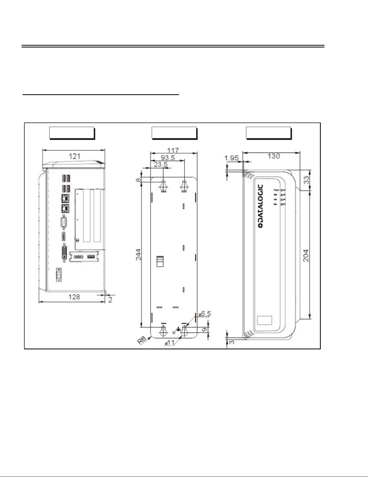
Processor Views and Dimensions
This section shows specifications for the Processor, including various views and dimensions.
Top View
Rear View Front View
UNITS: mm
13 Datalogic S.r.l.
Page 20

Processor Views and Dimensions MX-E Series Hardware Guide
Side View
UNITS: mm
Air Inlet
Filter Inside
Datalogic S.r.l. 14
Page 21

MX-E Series Hardware Guide Processor Installation
Processor Installation
Safety Instructions
Warning: There are no user-serviceable parts inside the device. To avoid electrical shock, never open the case.
Modifying or tampering with internal components will void the product warranty.
Attention: Il n'ya pas de pièces réparables par l'utilisateur à l'intérieur du matériel. Pour éviter un choc électrique,
n'ouvrez jamais le boîtier. L'ouverture du boîtier ou de retirer l'étiquette inviolable annulera la garantie du produit.
• Make sure heavy equipment is loaded evenly in the rack to avoid a hazardous condition. The rack should safely support
the combined weight of all the equipment it supports.
• Before the system is connected to the supply circuit, be sure to check equipment nameplate ratings to avoid overloading
circuits. Overloading may damage over-current protection devices and supply wiring.
• Slots and openings in the cabinet are provided for ventilation. To ensure sufficient air circulation for reliable system
operation, and to prevent overheating, maintain a minimum of 1.5 inches (38.1 mm) of clearance on the top and sides
of the cabinet and between MX-E Series Processors.
An optional power supply is available for MX-E Series Processors. If you provide your own, it must supply 24VDC at 5.5
A (nominal) with a safe operating ambient temperature range of 0° to +55° C (+32° to +131° F).
This equipment is to be powered by a Listed power supply for the U.S. and Canada, or a power supply that meets the
requirements for use where either IEC 60950 or EN60950 is applicable.
• To ensure safe operation, the system power must be properly grounded. If the unit is mounted within a rack, verify that
it is reliably connected to electrical ground. The ground terminal on the power input must be connected to the grounded
chassis/enclosure of the power supply. This insures electromagnetic compliance and proper operation. See “Grounding
Concepts” on page 18.
• The Processor is to be connected only to networks that do not route outside the plant.
Flat Surface Mounting
When mounting the MX-E Series Processor:
• Take environmental conditions into consideration.
• Mount the processor to a flat, stable, vibration-free surface.
• This processor is only certified for operation in closed rooms.
• Do not subject the processor to direct sunlight.
• Do not cover the ventilation holes.
• Mount the processor only in an upright position as shown in “Processor Views and Dimensions” on page 13.
• The wall or control cabinet must be able to withstand four times the total weight of the processor.
15 Datalogic S.r.l.
Page 22

Flat Surface Mounting MX-E Series Hardware Guide
• Do not exceed the flex radius of any connected cables.
Drilling Template
Mounting Hole
Dimensions
UNITS: mm.
NOTE: If the Processor uses a Compact Flash card, mount with the Processor top facing upward so the CF card
does not fall out due to vibration.
To mount the Processor:
1. Mark the surface mounting holes in the desired location using the drilling template dimensions.
2. Drill four surface mounting holes in the mounting surface. Use suitable anchors if necessary.
3. Insert four M5 mounting screws in the mounting holes and tighten them until approximately 0.2 inches (5 mm)
is left exposed. The mounting screws must be long enough to provide sufficient support.
4. Maneuver the Processor so mounting bracket slots align with the mounting screws.
5. Place the slots over the screws and slide the Processor down until the screws fit snugly into the mounting
bracket slots.
6. If necessary, tighten the mounting screws until snug.
Datalogic S.r.l. 16
Page 23

MX-E Series Hardware Guide Power Supply Connection
Power Supply Connection
Warning: To avoid electrical shock, disconnect all power to the power supply before working on it.
Avertissement: Pour éviter le choc électrique, débranchez toute la puissance à l'alimentation d'énergie avant de tra-
vailler à lui.
This equipment is to be powered by a Listed power supply for the U.S. and Canada, or a power supply that meets the
requirements for use where either IEC 60950 or EN60950 is applicable.
Wire the supplied power plug according to the chart shown below, then plug it into the power connector on the top of the
processor. The ground terminal (pin 2) on the +24V power input must be connected to the power supply’s grounded chassis/enclosure. This connection is needed to insure electromagnetic compliance and proper operation. See “Grounding
Concepts” on page 18.
Slot Number Signal Name
1 24 VDC Supply Minus
2 Chassis Ground
3 24 VDC Supply Plus
SUPPLIED POWER PLUG
Insert stripped wire into this hole
To open, insert a small screwdriver
into this slot and push down gently
on the screwdriver handle
Processor Power Connector
on top of processor
1 2 3
POWER 24 VDC*
Connect GND terminal to Power Supply Circuit Ground
Connect V- terminal to Power Supply Minus
Connect V+ terminal to Power Supply Plus*
*Note: The processor requires approximately 5.5 A @ 24VDC. We recommend using a 24 VDC
power supply capable of providing 5.5 A current. This voltage is commonly used in many
manufacturing environments.
17 Datalogic S.r.l.
Page 24

Grounding Concepts MX-E Series Hardware Guide
Grounding Concepts
Functional ground is a low impedance current path between electrical circuits and ground. It is used, for example, to
improve immunity to disturbances, but is not a protective measure. Grounding deflects disturbances, but does not necessarily provide protection against electric shock.
The functional ground on the processor has two connections:
• Supply voltage GND terminal
• Grounding connection on the processor back panel
To guarantee a good functional ground:
• Connect the processor to the central grounding point in the control cabinet using the shortest route possible.
• Use a cable with a minimum cross section of 2.5 mm² per connection. If a cable with wire tip sleeves is connected
to the supplied power plug, then a cable with maximum 1.5 mm² per connection is possible.
• Use shielded cable for all data connections.
Datalogic S.r.l. 18
Page 25
MX-E Series Hardware Guide USB Hardware Key
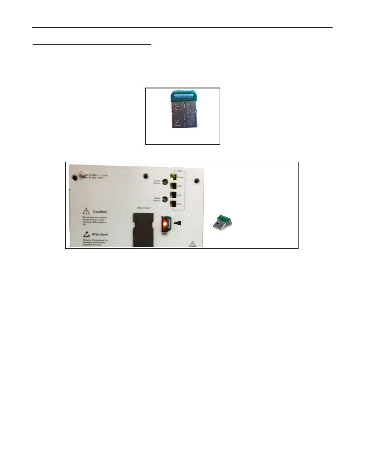
USB Hardware Key
A USB Hardware key, which contains license and processor configuration information, is ordered and shipped separately
from the processor. It must be present in the USB port labeled USB5 on the processor front before the processor is powered on.
The USB Hardware key
18 x 12 x 5 mm.
Processor Front View
A USB Hardware key is ordered and
shipped separately from the processor. It
must be present in the USB port labeled
USB5 on the processor front before the
processor is powered on.
19 Datalogic S.r.l.
Page 26
CFast Card MX-E Series Hardware Guide
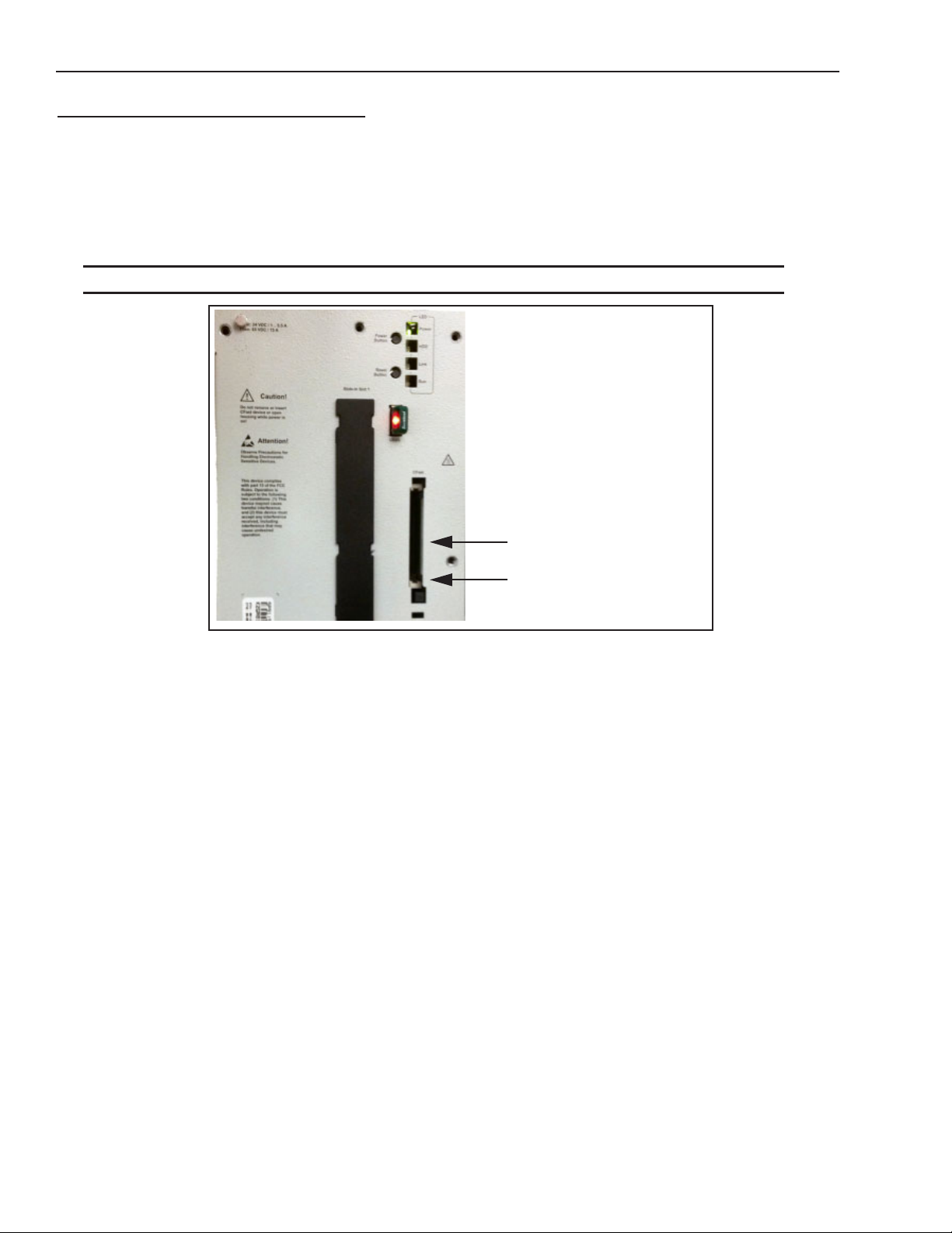
CFast Card
A CFast slot is located in the Processor front. A CFast card can be used as removable media for transferring data, performing upgrades, or for extended storage.
This CFast slot is connected to the chip set internally via SATA 1 with SATA III design (SATA 6 Gbit/s).
WARNING: Power must be disconnected before inserting or removing the CFast card.
Processor Front View
CFast Slot cover
Ejector (behind cover)
To exchange the CFast card
1. Press down on the slot cover’s top clip to open the slot.
2. Press the ejector at the bottom of the slot with a pointed object, such as a pen.
3. Pull the card straight out.
4. Insert the new card straight into the slot.
5. Close the slot cover.
Datalogic S.r.l. 20
Page 27
MX-E Series Hardware Guide Battery
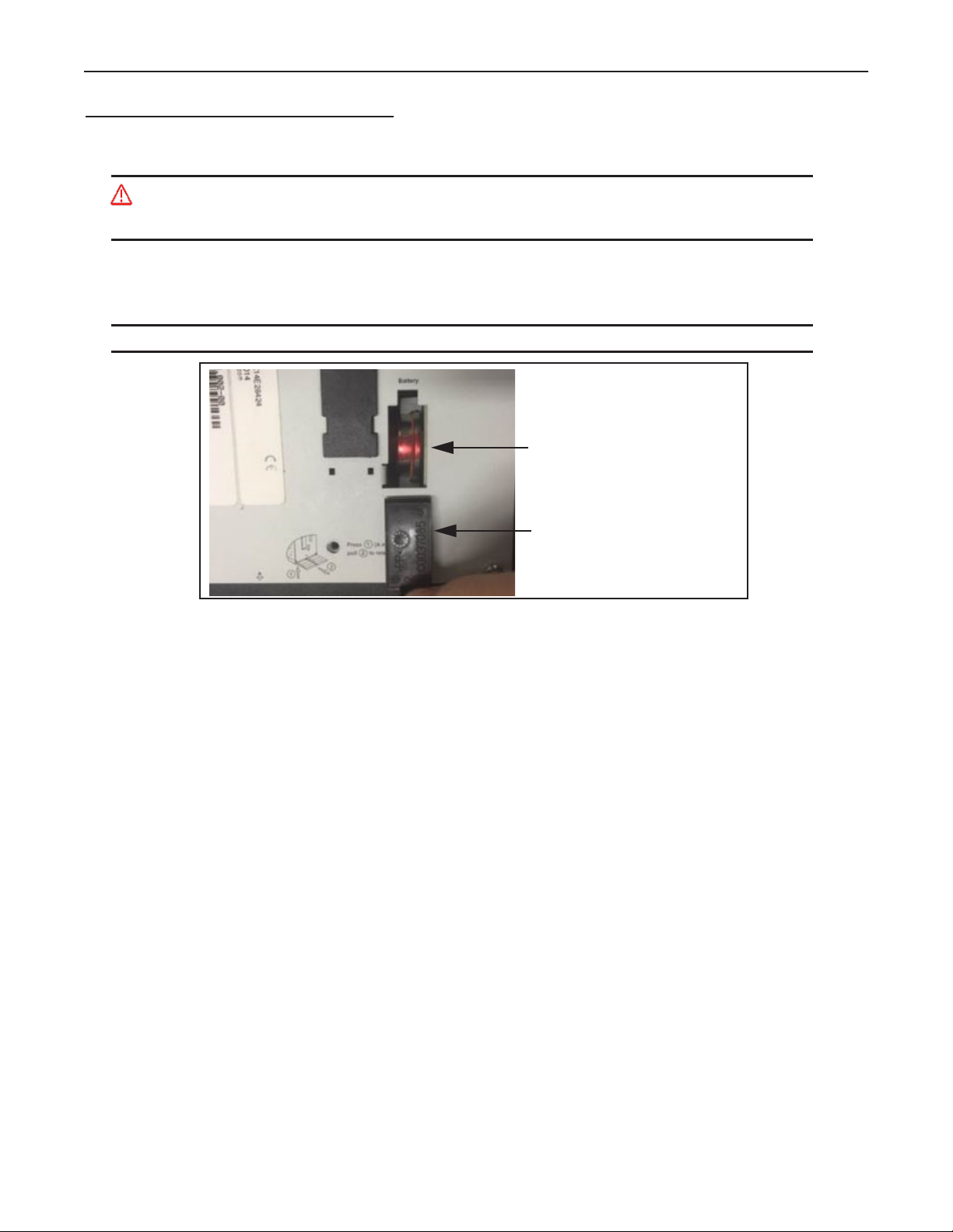
Battery
WARNING: Risk of explosion if battery is handled improperly or replaced by an incorrect type. Do not recharge,
disassemble, or dispose of in fire. Lithium batteries are considered hazardous waste. Dispose of used batteries
according to battery maker’s instructions or in accordance with applicable local regulations.
The lithium battery (CR2477N, 3 V, 950 mAh) powers the internal real-time clock (RTC). It is located behind the processor’s front cover. The battery has a limited service life and should be replaced at least every four years.
WARNING: Power must be disconnected before replacing the battery.
Processor Front View
Battery
Battery Slot cover open
To replace the battery
1. Disconnect the power supply to the processor.
2. Touch the housing or ground connection in order to discharge any electrostatic charge from your body.
3. Press down on the slot cover’s top clip to open the battery slot.
4. Do not hold the battery by its edges. Using the removal strip, carefully pull the battery out of its slot.
5. Insulated tweezers may be used to insert the new battery in the slot. Be sure the removal strip is in place to make
the next battery replacement easier.
6. Reconnect the power supply to the processor.
7. Reset the date and time in the BIOS.
21 Datalogic S.r.l.
Page 28

Battery MX-E Series Hardware Guide
Datalogic S.r.l. 22
Page 29

CHAPTER 3
M-Series and E-Series Cameras
Introduction
This section describes digital cameras provided by Datalogic S.r.l. and other third-party manufacturers. USB cameras will
not operate on an MX-E Series Processor.
Datalogic S.r.l. does not support the use of these cameras in any manner other than described herein.
E-Series cameras acquire an image when a signal is present on the trigger input of the camera trigger/power cable, then
digitize images at the camera source and transmit them directly to the processor over the Ethernet cable. These cameras
provide 8-bit resolution using internal 12-bit A/D converters and some have progressive scan shutter exposure (allowing
individual pixel readings). Third-party cameras may have different specifications. All cameras are capable of Gigabit
transmission rates.
E-Series cameras have a hard-coat finish case that helps eliminate ground loops. All camera settings (shutter, strobe, partial scan, etc.) are configured using Impact software and are maintained in the MX-E Series processors’ memory so there
are no physical switches on the cameras.
All camera settings must be configured using the Settings tab in the Vision Program Manager (VPM) or in the Settings
program. For more detailed information, refer to the Impact Reference Guide (843-0093).
IMPORTANT NOTE: We recommend that the sum of the pixel resolution of all the cameras connected to an MX processor not exceed thirty-two Megapixels. This limit is not enforced by Impact software, but, if the limit is exceeded, the
IMPACT user interface performance will degrade.
NOTE: The MX-E20 processor can accommodate a maximum of two cameras. The maximum image size of each camera
is two Megapixels. (The calculation is: maximum width in pixels * maximum height in pixels < 2,500,000.)
Safety Precautions
Read all of the following instructions before setting up your camera. Save this document for later use.
• Follow all warnings and instructions in this manual and in other user guides shipped with your hardware components.
• Do not attempt to disassemble the camera. Do not remove screws or attachments. There are no user-serviceable parts
inside. Refer servicing to Datalogic S.r.l.
• All E-Series and third-party cameras connect to the MX-E Series Processors using a Cat5E Ethernet cable (606-0677-
xx). Cat6 cable is required for distances greater than 25 meters. Using any other cable may cause intermittent data
transmission. Cameras connect to power and triggering signals using a cable and terminal block. See “Connecting the
Camera” on page 32 for more details.
23 Datalogic S.r.l..
Page 30

Safety Precautions MX-E Series Hardware Guide
NOTE: We recommend that you do not use a switch or a router between the MX-E Series Processor and the camera.
• This camera is designed for indoor use. Do not expose it to moisture, including rain or snow, and avoid operating it in
wet areas. Should the camera become wet, turn off the power immediately. Moisture can damage the camera and create
danger of electric shock. Avoid using the camera when the humidity is above 80%.
• Make sure your camera has enough airflow around it for proper ventilation. The safe case temperature during operation
is from 0° to 50° C (32° to 122° F).
• Mount the camera body in a fixed position where it will not be subject to excessive vibration.
• To reduce stress on the camera connectors and cable, loop the cables and fasten them to the camera's mounting block.
Do not crimp or tie the cables tightly with wire ties as this may damage them internally. The minimum cable bend
radius is fifteen times the cable diameter. It is not intended for continuous flexing or movement. Be sure that cables are
safely routed away from vehicle and pedestrian traffic.
• Check the intended installation area to be sure there is enough room for the camera and any lighting that may be
needed.
• Avoid areas with excessive heat, vibration, and environmental contaminants.
• Mount the camera away from devices that emit large amounts of electromagnetic energy.
• Do NOT attempt to clean the camera imager or imager cover. Do NOT spray the imager or imager cover with com-
pressed air as this may leave spots.
• Do not leave the camera imager uncovered. When you remove the lens cap, you must replace it with a lens.
Datalogic S.r.l. 24
Page 31

MX-E Series Hardware Guide M1xx and E1xx Camera Dimensions
M1xx and E1xx Camera Dimensions
These cameras weighs approximately 4 ounces (112 grams) with a mounting block, but without a lens.
Block Mounting holes
Fasteners provided
UNITS: inch [mm.]
Power/Trigger
Connection
2 x M5
0.31 [8] deep
3 x M3
0.79 [20]
1.0 [25]
0..5 [12]
0.74 [18.7]
Mounting Block (95A903029) and Camera Body
Bottom View
(also see “Mounting Block (95A903029)” on page 30)
1.65 [42]
2 x 1/4-20; 0.31 [8] deep
0.25 [6.3]
1.14 [29]
Ethernet
Connection
0.37 [9.5]
Rear View
1.14 [29]
Front View
25 Datalogic S.r.l.
Page 32

M2xx Camera Dimensions MX-E Series Hardware Guide
M2xx Camera Dimensions
The M2xx series of cameras weighs approximately 6.2 ounces (177 grams) with a mounting block, but without a lens.
Block Mounting bolts
M3; 4.5mm deep (2 ea.)
¼"-20; 8mm deep
(2 ea.)
0.25 [6.45]
UNITS: inch [mm.]
Ethernet
Connection
0.39 [10.0]
0.94 [23.9]
0.69 [17.5]
2.9 [73.7]
Mounting Block and Camera body
Bottom View
Power/Trigger
Connection
0.39 [10.0]
M5 x 0.8; 8mm deep
(2 ea.)
0.21 [5.4]
0.79 [20]
Rear View
1.14 [29]
0.37 [9.5]
1.7 [44]
Front View
Datalogic S.r.l. 26
Page 33

MX-E Series Hardware Guide M3xx Camera Dimensions
M3xx Camera Dimensions
The M3xx series of cameras weighs approximately 8.5 ounces (242 grams) with a mounting block, but without a lens
Block Mounting bolts
M3; 4.5mm deep (2 ea.)
¼"-20; 8mm deep
(2 ea.)
0.25 [6.45]
UNITS: inch [mm.]
Ethernet
Connection
0.39 [10.0]
0.94 [23.9]
0.69 [17.5]
3.41 [86.7]
Mounting Block and Camera body
Bottom View
Power/Trigger
Connection
0.39 [10.0]
M5 x 0.8; 8mm deep
(2 ea.)
0.21 [5.4]
0.79 [20]
Rear View
1.14 [29]
0.37 [9.5]
1.7 [44]
Front View
27 Datalogic S.r.l.
Page 34

M565/M570/M575/M580 Camera Dimensions MX-E Series Hardware Guide
M565/M570/M575/M580 Camera Dimensions
The camera weighs approximately 8 ounces (240 grams) without a lens. With an F-mount lens adapter the weight is
approximately 11.6 ounces (330 grams).
A = I/O Connection
B = Power Connection
C =Ethernet Connection
Green LED = Connection Active
Yellow LED = Data Transfer
C
UNITS: mm.
B
A
Bottom View
Rear View
Front View
Datalogic S.r.l. 28
Page 35

MX-E Series Hardware Guide M6xx Camera Dimensions
M6xx Camera Dimensions
The M6xx series of cameras weighs approximately 1.9 ounces (53 grams) without a lens.
0.788 [20]
Mounting Holes
M2; 4 mm deep (2 ea.)
0.473 [12]
UNITS: inch [mm.]
0.591 [15]
0.5 [12]
0.79 [20]
0.866 [22.0]0.65 [16.5]
0.933 [23.7]
1.575 [40]
Camera body Bottom View
Mounting Holes
M2; 3mm deep (4 ea.)
Mounting Holes
M3; 3 mm deep (3 ea.)
0.25 [6.3]
1.14 [29]
Ethernet/POE
Connection
Trigger Connection
Rear View
0.79 [20]
1.14 [29]
Front View
Mounting the Camera
This section provides instructions for mounting Datalogic cameras. For information about third-party cameras, consult the
manufacturer’s documentation for those cameras.
To mount an M1xx or E1xx camera
1. With the mounting block held tightly against the camera body, insert the mounting bolts through the mounting
bolt holes (see diagram below).
2. Turn the mounting bolt clockwise to tighten the block and secure it to the camera.
29 Datalogic S.r.l.
Page 36

Mounting the Camera MX-E Series Hardware Guide
3. Use appropriately sized fasteners in the pre-threaded holes in the bottom of the mounting bracket to secure the
mounting block to a rigid surface for proper stability and heat transfer. (See “M1xx and E1xx Camera Dimensions” on page 25.)
Mounting Block
(95A903029)
M5 x 0.8; 8mm deep
(2 ea.)
.25 [6.25]
Block Mounting bolts
M3 (3 ea.)
Camera front
0.14 [13.5]
Block Mounting bolts
M3; 4.5mm deep (2 ea.)
Camera front faces
this direction
0.59 [15]
0.24 [6]
.5 [13]
0.39 [10.0]
1.18 [30]
Bottom View
Mounting Block
(381-1355)
0.53 [13.35]
1.06 [27]
UNITS: inch [mm.]
¼"-20; 8mm deep
(2 ea.)
M5 x 0.8; 8mm deep
(2 ea.)
UNITS: inch [mm.]
¼"-20; 8mm deep
(2 ea.)
0.69 [17.4]
Bottom View
0.39 [10.0]
1.65 [42]
Datalogic S.r.l. 30
Page 37

MX-E Series Hardware Guide Mounting the Camera
To mount an M2xx or M3xx camera
1. With the mounting block held tightly against the camera body, insert two mounting bolts through the mounting
bolt holes (see diagram below).
2. Turn the mounting bolt clockwise to tighten the block and secure it to the camera.
3. Use appropriately sized fasteners in the pre-threaded holes in the bottom of the mounting bracket to secure the
mounting block to a rigid surface for proper stability and heat transfer. (See “M2xx Camera Dimensions” on
page 26 and “M3xx Camera Dimensions” on page 27.)
Camera Front
Mounting Bolts M3 (2 ea.)
M2xx and M3xx Mounting Block
(381-1354)
To mount an M565/M570/M575/M580 camera
1. With the camera body held tightly against the desired mounting surface, insert two mounting bolts through the
mounting surface and into the mounting bolt holes (see diagram below).
Mounting Bolt holes M4 (2 ea.)
Bottom View
To mount an M6xx camera
1. With the camera body held tightly against the desired mounting surface, insert appropriately sized mounting bolts
through the mounting surface and into the mounting bolt holes on the bottom of the camera (see “M6xx Camera
Dimensions” on page 29).
31 Datalogic S.r.l.
Page 38

Connecting the Camera MX-E Series Hardware Guide
Connecting the Camera
WARNING: Never wire M1xx or E1xx Camera Strobe Outputs in parallel with M1xx, E1xx, M2xx, or M3xx Camera
Strobe Outputs. This will damage the cameras.
M1xx and E1xx Camera Connection
To connect M1xx and E1xx camera trigger signals and strobe outputs, use cable 606-0674-xx (6
pin Hirose Male to DB9) with terminal block 661-0399.
Terminal Name Signal Notes
Optional Camera
Power
DO NOT USE Do NOT apply power to this terminal if
power is supplied by Power over
Ethernet (PoE
; enable/disable in
VPM-Settings)
Optional Camera
Power Ground
DO NOT USE Not required if ground is supplied by
Power Over Ethernet (PoE
in VPM-Settings)
I/O Ground I/O Ground
Trigger In** Camera Trigger In 0 to +24 VDC recommended
Maximum +30 VDC
As sinking input
Off: 0 to +1.4 VDC
On: +2.2 to +24 VDC; 5 to 15 ma
As sourcing input (see Trigger Pullup +VCC)
Off: +2.2 to +24 VDC; 5 to 15 ma
On: 0 to +1.4 VDC
Trigger Pullup
+VCC**
Strobe Output
Pullup +VCC*
Strobe Trigger
Output*
Trigger In Pullup - use if
Trigger In needs sourcing (see Note 1 below)
Strobe Supply Voltage use if Strobe Trigger
Output needs sourcing
(see Note 2 below)
Trigger Out to Strobe
(see Note 3 below)
+24 VDC recommended
Maximum +30 VDC
(**Block contains 1.6k Ohm 1W resistor between Trigger In and
Trigger Pullup +VCC)
Based on Strobe requirement (optional)
Max: +30 VDC; 50 ma
(*Block contains 1.6k Ohm 1W resistor between Strobe Trigger
Output and Strobe Output Pullup +VCC)
DO NOT APPLY ANY VOLTAGE DIRECTLY TO THIS OUTPUT.
DO NOT WIRE OUTPUTS IN PARALLEL.
; enable/disable
NOTE 1: If Camera Trigger In requires a sinking signal, set the Software Trigger Event to Rising Edge. If it requires a
sourcing signal, set the Software Trigger Event to Falling Edge.
NOTE 2: If Strobe Trigger Output requires a sinking signal, set the Strobe Trigger Output to Falling Edge. If it requires a
sourcing signal, set the Strobe Trigger Output to Rising Edge.
NOTE 3: Disconnecting the camera will turn on some strobe lights.
Datalogic S.r.l. 32
Page 39

MX-E Series Hardware Guide M1xx and E1xx Camera Connection
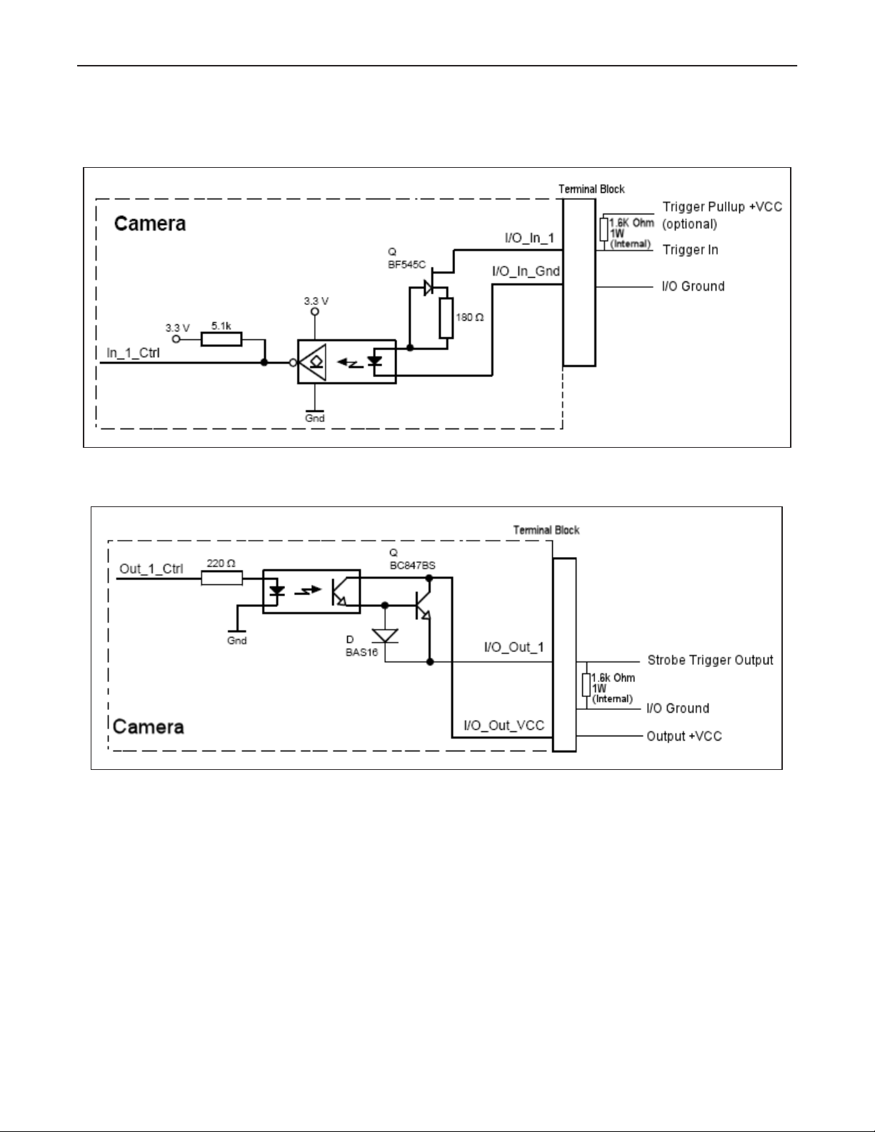
M1xx and E1xx Circuit Diagrams
M1xx Trigger In Circuit
WARNING: Never wire M1xx or E1xx Camera Strobe Outputs in parallel with M1xx, E1xx, M2xx, or M3xx Camera
Strobe Outputs. This will damage the cameras.
M1xx Strobe Trigger Output Circuit
661-0399 Terminal Block Dimensions
33 Datalogic S.r.l.
Page 40

M1xx and E1xx Camera Connection MX-E Series Hardware Guide
M1xx and E1xx Terminal Connections
The response times for the strobe output on the M1xx and E1xx camera will typically fall into the ranges specified below.
The exact response time for your application will depend on the external resistor and the applied voltage you use.The
shutter begins opening simultaneously with the “Camera Strobe Output” in the diagram. Set the strobe time 60 to 110
Datalogic S.r.l. 34
Page 41

MX-E Series Hardware Guide M1xx and E1xx Camera Connection
microseconds longer than you would on a M2xx to account for the delays. The shutter time must then be set a little longer
than the strobe time.
Time Delay Rise (TDR) = 40 us
Rise Time (RT) = 20 us to 70 us
Time Delay Fall (TDF) = 0.6 us
Fall Time (FT) = 0.7 us to 1.4 us
35 Datalogic S.r.l.
Page 42

M2xx and M3xx Camera Connection MX-E Series Hardware Guide
M2xx and M3xx Camera Connection
To connect M2xx and M3xx camera power, trigger signals, and strobe outputs, use cable 6060673-xx (12-pin Hirose Male to HD-15) with terminal block 661-0400.
Terminal Signal Name Notes
Camera Power Ground Camera Ground
I/O Ground I/O Ground
Camera Power +VDC Camera Power +12 to +24 VDC recommended
@ 500 mA Max
Maximum: +30 VDC
Output +VCC Power for Strobe Trigger Out +3.3 to +24 VDC; 50 mA Max
Maximum: +30 VDC
Input 2 Pullup +VCC DO NOT USE Not Currently Supported
Trigger Pullup +VCC Trigger In Pullup - use if
Trigger In needs sourcing
input
Trigger In Camera Trigger In (see Note
1 below)
Input 2 DO NOT USE Not Currently Supported
Strobe Trigger Out Trigger Out to Strobe (see
Note 2 below)
Output 2 DO NOT USE Not Currently Supported
Output 3 DO NOT USE Not Currently Supported
Output 4 DO NOT USE Not Currently Supported
Recommended: +24 VDC
0 to +24 VDC recommended
Maximum +30 VDC
As sinking input
Off: 0 to +1.4 VDC
On: +2.2 to +24 VDC; 5 to 15 ma
As sourcing input (see Trigger Pullup +VCC)
Off: +2.2 to +24 VDC; 5 to 15 ma
On: 0 to +1.4 VDC
DO NOT APPLY GROUND DIRECTLY TO THIS OUTPUT.
NOTE 1: If Camera Trigger In requires a sinking signal, set the Software Trigger Event to Rising Edge. If it requires a
sourcing signal, set the Software Trigger Event to Falling Edge.
NOTE 2: If Strobe Trigger Output requires a sinking signal, set the Strobe Trigger Output to Falling Edge. If it requires a
sourcing signal, set the Strobe Trigger Output to Rising Edge.
Datalogic S.r.l. 36
Page 43

MX-E Series Hardware Guide M2xx and M3xx Camera Connection
M2xx and M3xx Circuit Diagrams
M2xx and M3xx Trigger In Circuit
M2xx and M3xx Strobe Trigger Out Circuit
661-0400 Terminal Block Dimensions
37 Datalogic S.r.l.
Page 44

M2xx and M3xx Camera Connection MX-E Series Hardware Guide
M2xx and M3xx Terminal Connections
Datalogic S.r.l. 38
Page 45

MX-E Series Hardware Guide M565/M570/M575/M580 Camera Connection
The response times for the strobe output on the M2xx and M3xx cameras will typically fall into the ranges specified
below. The exact response time for your application will depend on the external resistor and the applied voltage you use.
Time Delay Rise (TDR) = 1.5 us
Rise Time (RT) = 1.3 - 5.0 us
Time Delay Fall (TDF) = 1 - 20 us
Fall Time (FT) = 1 - 5 us
M565/M570/M575/M580 Camera Connection
To connect one of these cameras, use terminal block 661-0401 with cable 606-0673-xx (12-pin
to HD-15 camera I/O) and cable 606-0674-xx (6 pin to DB9 camera power). For details about
programming the Line Trigger, refer to the Impact Reference Guide (843-0093)
NOTE: Do NOT use the M2xx/M3xx terminal block (661-0400) or M1xx block (661-0399) to
connect this camera. They will NOT provide the correct signal levels.
Terminal Signal Name Notes
Camera Power Ground Camera Ground See Note 1 Below
I/O Ground I/O Ground See Note 1 Below
Camera Power
+12VDC
Input 1 - No Connection DO NOT USE
Input 1 + Frame Start Trigger As sinking input
Camera Power +12 VDC (+-10%) @ 700 mA Max
Off 0 to +0.8 VDC
On: +2.0 to +5 VDC
As sourcing input (see Input 1 Pullup)
Off: +2.0 to +5 VDC
On 0 to +0.8 VDC
Maximum: +5 VDC
Input 2 - No Connection DO NOT USE
39 Datalogic S.r.l.
Page 46

M565/M570/M575/M580 Camera Connection MX-E Series Hardware Guide
Terminal Signal Name Notes
Input 2 + Single Line Trigger
OR
Phase A Line Trigger
(Quadrature Encoder)
Input 3 - No Connection DO NOT USE
Input 3 + Phase B Line Trigger
(Quadrature Encoder)
Output 1 - Not Currently Supported DO NOT USE
Output 1 + Not Currently Supported DO NOT USE
Output 2 - Not Currently Supported DO NOT USE
Output 2 + Not Currently Supported DO NOT USE
Input 1 Pullup +5VDC Frame Start Trigger Pullup -
use if Input 1 needs sourcing
input
Input 2 Pullup +5VDC Line Trigger Pullup - use if
Input 2 needs sourcing input
As sinking input
Off 0 to +0.8 VDC
On: +2.0 to +5 VDC
As sourcing input (see Input 2 Pullup)
Off: +2.0 to +5 VDC
On 0 to +0.8 VDC
Maximum: +5 VDC
As sinking input
Off 0 to +0.8 VDC
On: +2.0 to +5 VDC
As sourcing input (see Input 3 Pullup)
Off: +2.0 to +5 VDC
On 0 to +0.8 VDC
Maximum: +5 VDC
Maximum: +5 VDC
Maximum: +5 VDC
Input 3 Pullup +5VDC Line Trigger Pullup - use if
Input 3 needs sourcing input
Maximum: +5 VDC
NOTE 1: To help prevent ground loops and possible false triggering, we recommend connecting I/O Ground to Camera
Power Ground.
Datalogic S.r.l. 40
Page 47

MX-E Series Hardware Guide M565/M570/M575/M580 Camera Connection
M565/M570/M575/M580 Circuit Diagrams
Frame Trigger Input Circuit
Single Line Trigger Input Circuit
41 Datalogic S.r.l.
Page 48

M565/M570/M575/M580 Camera Connection MX-E Series Hardware Guide
Quadrature Encoder Line Trigger Input Circuit
661-0401 Terminal Block Dimensions
Datalogic S.r.l. 42
Page 49

MX-E Series Hardware Guide M565/M570/M575/M580 Camera Connection
Terminal Connections
Unterminated Cable Connections
43 Datalogic S.r.l.
Page 50

M6xx Camera Connection MX-E Series Hardware Guide
M6xx Camera Connection
To connect M6xx camera trigger signals and strobe outputs, use cable 606-0674-xx (6 pin
Hirose Male to DB9) with terminal block 661-0399.
Terminal Name Signal Notes
Optional Camera
Power
DO NOT USE Do NOT apply power to this terminal if
Power is supplied by Power over
Ethernet (PoE
; enable/disable in
VPM-Settings)
Optional Camera
Power Ground
DO NOT USE Not required if Ground is supplied by
Power Over Ethernet (PoE
; enable/disable
in VPM-Settings)
I/O Ground I/O Ground
Trigger In** Camera Trigger In 0 to +24 VDC (recommended
Maximum +24 VDC
As sinking input
Off: 0 to + 0.5 VDC
On: +3.3 to +24 VDC; 5 to 15 ma
As sourcing input (see Trigger Pullup +VCC)
Off: +3.3 to +24 VDC; 5 to 15 ma
On: 0 to + 0.5 VDC
Trigger Pullup
+VCC**
Strobe Output
Pullup +VCC*
Strobe Trigger
Output*
Trigger In Pullup - use if
Trigger In needs sourcing (see Note 1 below)
Strobe Supply Voltage use if Strobe Trigger
Output needs sourcing
(see Note 2 below)
Trigger Out to Strobe
(see Note 3 below)
+24 VDC recommended
Maximum +24 VDC
(**Block contains 1.6k Ohm 1W resistor between Trigger In and
Trigger Pullup +VCC)
Based on Strobe requirement (optional)
Max: +30 VDC; 50 ma
(*Block contains 1.6k Ohm 1W resistor between Strobe Trigger
Output and Strobe Output Pullup +VCC)
DO NOT APPLY ANY VOLTAGE DIRECTLY TO THIS OUTPUT.
DO NOT WIRE OUTPUTS IN PARALLEL.
NOTE 1: If Camera Trigger In requires a sinking signal, set the Software Trigger Event to Rising Edge. If it requires a
sourcing signal, set the Software Trigger Event to Falling Edge.
NOTE 2: If Strobe Trigger Output requires a sinking signal, set the Strobe Trigger Output to Falling Edge. If it requires a
sourcing signal, set the Strobe Trigger Output to Rising Edge.
NOTE 3: Disconnecting the camera will turn on some strobe lights.
Datalogic S.r.l. 44
Page 51

MX-E Series Hardware Guide M6xx Camera Connection
M6xx Circuit Diagrams
M6xx Trigger In Circuit
WARNING: Never wire M6xx Camera Strobe Outputs in parallel with M1xx, M2xx, or M3xx Camera Strobe Outputs.
This will damage the cameras.
M6xx Strobe Trigger Output Circuit
661-0399 Terminal Block Dimensions
45 Datalogic S.r.l.
Page 52

Third-party Cameras MX-E Series Hardware Guide
M6xx Terminal Connections
Third-party Cameras
The MX-E Series Processor and Impact Software support only the third-party cameras listed in this section. This information, including power and trigger signal connections, are provided by us as a convenience. You must purchase a license
from us to connect a third-party camera to the M-Series processor.
Datalogic assumes no responsibility for the accuracy or timeliness of this third-party camera information.
For complete details and the most accurate specifications for these cameras, consult the manufacturer’s documentation.
Datalogic S.r.l. 46
Page 53

MX-E Series Hardware Guide JAI Cameras
JAI Cameras
NOTE: See “JAI Camera I/O Signals” on page 54 for important information about camera and strobe signals.
Model
(GigE)
AT-200GE* 2 Yes 1624 1236 10.3.0
AM-800GE 8 No 3296 2472 10.3.0
AM-1600-GE 16 No 4872 3248 10.6.0
CM-140GE 1.4 No 1392 1040 11.0.0
AT-140GE* 1.4 Yes
CM-140GE-UV 1.4 Ultraviolet 1392 1040 10.2.0
CM-030GE-RH
(remote head)
Resolution
(Megapixels)
0.3 No 659 494 10.2.0
Color Image
Horizontal
1392 1040 10.5.0
(3 CCD)
Image Vertical Minimum Software Ver-
sion Required
*See “Color shading support” on page 53 for special camera configuration settings.
JAI Camera Connection
To connect JAI camera power, trigger signals, and strobe outputs, use cable 606-0673-xx
(12-pin to HD-15) with terminal block 661-0402.
NOTE: Do NOT use terminal block 248-0141 to connect this camera. It will NOT provide
the correct signal levels.
WARNING: THE POWER AND GROUND CONNECTIONS FOR THIS CAMERA
ARE DIFFERENT FROM OUR CAMERAS AND OTHER THIRD-PARTY CAMERAS. USE CAUTION WHEN CONNECTING POWER TO THESE CAMERAS.
Terminal Signal Name Notes
Camera Power
Ground
Camera Power
+12VDC
Trigger Input - Camera Trigger -
47 Datalogic S.r.l.
Camera Ground
Camera Power CM-140GE-UV and CM-030-GE-RH
+12 VDC @ 350 mA Max (4.1 W)
Maximum: +13.2 VDC
AM-800GE
+12VDC to +24VDC ±10%, 8.16W (at normal, Full resolution, DC+12V)
AT-200GE
+10.8VDC to +26.4VDC, 0.67 A (Typical, Full frame, DC
+12V in)
AM-1600GE
+12.0VDC ±10%, 7.5W (Typical, Continuous Mode)
Page 54

JAI Cameras MX-E Series Hardware Guide
Terminal Signal Name Notes
Trigger Input + Camera Trigger + +0 to +24 VDC
Off: 0 to +2.0 VDC
On: +4.0 to + 24 VDC
Maximum: +24 VDC
Input 2 - Not Currently Supported DO NOT USE
Input 2 + Not Currently Supported DO NOT USE
Strobe Output - Strobe Output Ground
Strobe Output +VCC Power for Strobe Output +5 to +24 VDC
Maximum: +24 VDC; 100 mA
Output 2 - Not Currently Supported DO NOT USE
Output 2 +VCC Not Currently Supported DO NOT USE
Strobe Output
Pull down GND
Output 2 Pull down
GND
Strobe Output Pull down use if Strobe Output needs
sourcing output
Not Currently Supported DO NOT USE
JAI Camera Circuit Diagrams
JAI Camera Trigger Input Circuit (sourcing)
JAI Camera Trigger Input Circuit (sinking)
Datalogic S.r.l. 48
Page 55

MX-E Series Hardware Guide JAI Cameras
JAI Camera Strobe Output Circuit (sinking)
JAI Camera Strobe Output Circuit (sourcing)
JAI Camera Strobe Output Circuits
SinkingSourcing
49 Datalogic S.r.l.
Page 56

JAI Cameras MX-E Series Hardware Guide
661-0402 Terminal Block Dimensions
Datalogic S.r.l. 50
Page 57

MX-E Series Hardware Guide JAI Cameras
JAI Terminal Connections
JAI Terminal Connections (sourcing)
51 Datalogic S.r.l.
Page 58

JAI Cameras MX-E Series Hardware Guide
JAI Terminal Connections (sinking)
Datalogic S.r.l. 52
Page 59

MX-E Series Hardware Guide JAI Cameras
JAI Unterminated Cable Connections
JAI Camera Unterminated Cable Connections
Sourcing Example
Color shading support
The JAI Model AT-200GEcamera has several special features that are not supported by the standard VPM camera setup.
One of these features is color shading. Color shading corrects for image shading, particularly darkening in the corners.
You can use the color shading feature of this camera after you complete the following offline calibration procedure.
To calibrate color shading
1. Using the optics and lighting for the application, place a white or gray target that fills the field-of-view.
2. Using VPM camera settings, set the white balance to factory defaults. You should re-calibrate the white balance
after the shading is corrected.
3. Adjust the exposure and other settings to create a grey level of 50 to 75% at the center of the image. Note the
exposure setting.
4. Close VPM and IMPACTDevice.exe.
5. Start the Pylon Viewer by double-clicking on the following file:
c:\Program Files\Basler\Pylon 2.x\apps\i386\PylonViewerApp.exe
Note that Pylon Viewer and IMPACTDevice.exe cannot run at the same time.
53 Datalogic S.r.l.
Page 60

JAI Cameras MX-E Series Hardware Guide
6. In the Devices window, select the camera to be calibrated.
7. Switch to the Feature window.
8. Set the Transport Layer/Read Timeout and the Write Timeout to 3000.
9. Set the User Set Selector to Default and click the User Set Load button.
10. Set the Acquisition Control/Exposure Mode to Timed.
11. Set the Acquisition Control/Exposure Time to the setting found in Step 3 using VPM.
12. Snap and image using the One Shot button. An image should be displayed.
13. Verify that the image pixel values are medium intensity, not saturated or very dark. Adjust the exposure time and
other settings, if necessary.
14. Move to the JAI Custom Control area of the Feature Window.
15. Select the preferred Shading Correction Mode. You will probably want Flat Shading, which corrects for both
brightness variations and color variations. The other option of Color Shading will only correct for color variation
and leaves brightness variation uncorrected.
16. Set Shading Selector to Red.
17. Turn On Shading Enable.
18. Click the Shading Correct Execute button.
19. Repeat steps 16, 17, and 18 for Green and Blue.
20. In the User Set Control area, set User Set Selector to User Set 1 and click the User Set Save button.
21. Close the Pylon Viewer and restart IMPACTDevice.exe and VPM.
22. The camera will now load the shading correction each time it starts.
23. Recalibrate the White Balance.
JAI Camera I/O Signals
On JAI camera models AT200-GE and AM-800GE, the camera software setup in Vision Program Manager (VPM) provides a camera trigger delay debounce setting, but no holdoff debounce setting. VPM also does not provide a strobe trigger pulse width setting. The strobe trigger pulse width coincides with the camera shutter speed open time setting so that it
turns on when the exposure starts (shutter opens) and turns off when the exposure ends (shutter closes). Refer to “Trigger
Events” and “Strobe Pulse Length” in the Impact Reference Guide (843-0093) for more details.
Datalogic S.r.l. 54
Page 61

MX-E Series Hardware Guide Basler Cameras
Basler Cameras
The MX-E Series Processor and Impact Software can support a wide variety of Basler GigE cameras, in addition to the
models listed below, including all Ace and Scout models. Ace model numbers begin with “acA” and Scout model numbers begin with “scA.” For complete details and the most accurate specifications for these cameras, consult the manufacturer’s documentation.
Datalogic assumes no responsibility for the accuracy or timeliness of this third-party camera information.
You must purchase a license from Datalogic to connect a third-party camera to the MX-E Series processor.
Basler Aviator Cameras
Model
(GigE)
avA1000-100gm
avA1000-100gc
avA1600-50gm
avA1600-50gc
avA1900-50gm
avA1900-50gc
avA2300-25gm
avA2300-25gc
Resolution
(Megapixels)
1No
1No
2No
3No
Color Image
Yes
Yes
Yes
Yes
Image Vertical FPS
Horizontal
1024 1024 101 10.3.0
1600 1200 55 10.3.0
1920 1080 51 10.3.0
2239 1750 26 10.3.0
(approx)
Camera Connection
WARNING: THIRD-PARTY CAMERA REQUIREMENTS ARE DIFFERENT. THESE
CAMERAS REQUIRE +12 VDC POWER. USE CAUTION WHEN CONNECTING
POWER TO THESE CAMERAS.
To connect power, trigger signals, and strobe outputs for these Basler camera models, use
cable 606-0673-xx (12-pin Hirose Male to HD-15) with terminal block 661-0400.
Terminal Signal Name Notes
Camera Power Ground Camera Ground
Minimum Software
Version Required
I/O Ground I/O Ground
Camera Power +VDC Camera Power +12 VDC recommended @ 500 mA Max
Maximum: +13.2 VDC
Output +VCC Power for Strobe Trigger Out +3.3 to +24 VDC; 50 mA Max
Maximum: +30 VDC
Input 2 Pullup +VCC DO NOT USE Not Currently Supported
Trigger Pullup +VCC Trigger In Pullup - use if
Trigger In needs sourcing
input
55 Datalogic S.r.l.
Recommended: +24 VDC
Page 62

Basler Cameras MX-E Series Hardware Guide
Terminal Signal Name Notes
Trigger In Camera Trigger In (see Note
1 below)
Input 2 DO NOT USE Not Currently Supported
Strobe Trigger Out Trigger Out to Strobe (see
Note 2 below)
Output 2 DO NOT USE Not Currently Supported
Output 3 DO NOT USE Not Currently Supported
Output 4 DO NOT USE Not Currently Supported
0 to +24 VDC recommended
Maximum +30 VDC
As sinking input
Off: 0 to +1.4 VDC
On: +2.2 to +24 VDC; 5 to 15 ma
As sourcing input (see Trigger Pullup +VCC)
Off: +2.2 to +24 VDC; 5 to 15 ma
On: 0 to +1.4 VDC
DO NOT APPLY GROUND DIRECTLY TO THIS OUTPUT.
NOTE 1: If Camera Trigger In requires a sinking signal, set the Software Trigger Event to Rising Edge. If it requires a
sourcing signal, set the Software Trigger Event to Falling Edge.
NOTE 2: If Strobe Trigger Output requires a sinking signal, set the Strobe Trigger Output to Falling Edge. If it requires a
sourcing signal, set the Strobe Trigger Output to Rising Edge.
Datalogic S.r.l. 56
Page 63
MX-E Series Hardware Guide Basler Cameras
Circuit Diagrams
Trigger In Circuit
Strobe Trigger Out Circuit
57 Datalogic S.r.l.
Page 64

Basler Cameras MX-E Series Hardware Guide
Terminal Connections
Datalogic S.r.l. 58
Page 65

MX-E Series Hardware Guide Basler Cameras
Aviator Unterminated Cable Connections
Unterminated Cable Connections
59 Datalogic S.r.l.
Page 66

Basler Line Scan Camera MX-E Series Hardware Guide
Basler Line Scan Camera
Model
(GigE)
ruL2098-10gc 2098 pixels
raL8192-12gm 8192 pixels
Sensor Size Color Maximum Line
Rate
Yes 9.2 kHz 14 x 14 μm 1988 pixels 11.5.0
x 3 lines
No 12 kHZ 3.5 x 3.5 μm 12288 pixels 11.7.0
x 1 line
Pixel Size Maximum
Frame
Height
Minimum Software
Version Required
Basler Line Scan Camera Connection
This section includes information for the Basler color line scan camera model ruL2098-10gc
and monochrome model raL8192-12gm.
To connect the camera, use terminal block 661-0401 with cable 606-0673-xx (12-pin to HD15 camera I/O) and cable 606-0674-xx (6 pin to DB9 camera power). For details about programming the Line Trigger, refer to the Impact Reference Guide (843-0093)
NOTE: Do NOT use the M2xx/M3xx terminal block (661-0400) or M1xx block (661-0399) to connect this camera. They
will NOT provide the correct signal levels.
Terminal Signal Name Notes
Camera Power Ground Camera Ground See Note 1 Below
I/O Ground I/O Ground See Note 1 Below
Camera Power
+12VDC
Input 1 - No Connection DO NOT USE
Input 1 + Frame Start Trigger As sinking input
Input 2 - No Connection DO NOT USE
Input 2 + Single Line Trigger
Input 3 - No Connection DO NOT USE
Camera Power +12 VDC (+-10%) @ 500 mA Max
Off 0 to +0.8 VDC
On: +2.0 to +5 VDC
As sourcing input (see Input 1 Pullup)
Off: +2.0 to +5 VDC
On 0 to +0.8 VDC
Maximum: +5 VDC
As sinking input
OR
Phase A Line Trigger
(Quadrature Encoder)
Off 0 to +0.8 VDC
On: +2.0 to +5 VDC
As sourcing input (see Input 2 Pullup)
Off: +2.0 to +5 VDC
On 0 to +0.8 VDC
Maximum: +5 VDC
Datalogic S.r.l. 60
Page 67

MX-E Series Hardware Guide Basler Line Scan Camera Connection
Terminal Signal Name Notes
Input 3 + Phase B Line Trigger
(Quadrature Encoder)
Output 1 - Not Currently Supported DO NOT USE
Output 1 + Not Currently Supported DO NOT USE
Output 2 - Not Currently Supported DO NOT USE
Output 2 + Not Currently Supported DO NOT USE
Input 1 Pullup +5VDC Frame Start Trigger Pullup -
use if Input 1 needs sourcing
input
Input 2 Pullup +5VDC Line Trigger Pullup - use if
Input 2 needs sourcing input
Input 3 Pullup +5VDC Line Trigger Pullup - use if
Input 3 needs sourcing input
As sinking input
Off 0 to +0.8 VDC
On: +2.0 to +5 VDC
As sourcing input (see Input 3 Pullup)
Off: +2.0 to +5 VDC
On 0 to +0.8 VDC
Maximum: +5 VDC
Maximum: +5 VDC
Maximum: +5 VDC
Maximum: +5 VDC
NOTE 1: To help prevent ground loops and possible false triggering, you must connect I/O Ground to Camera Power
Ground.
61 Datalogic S.r.l.
Page 68

Basler Line Scan Camera Connection MX-E Series Hardware Guide
Basler Model ruL2098-10gc/raL8192-12gm Line
Scan Circuit Diagrams
Frame Trigger Input Circuit
Single Line Trigger Input Circuit
Datalogic S.r.l. 62
Page 69

MX-E Series Hardware Guide Basler Line Scan Camera Connection
Quadrature Encoder Line Trigger Input Circuit
661-0401 Terminal Block Dimensions
63 Datalogic S.r.l.
Page 70

Basler Line Scan Camera Connection MX-E Series Hardware Guide
Terminal Connections
Unterminated Cable Connections
Datalogic S.r.l. 64
Page 71

MX-E Series Hardware Guide Baumer Cameras
Baumer Cameras
Model numbers that include a “C” are color cameras.
Model
(GigE)
TXG02 - TXG02c .3 656 494 140 11.5.0
TXG03 - TXG03c .3 656/656 494/490 90 11.5.0
TXG04 - TXG04c .3 656/656 494/490 56 11.5.0
TXG04h .3 640 480 210 11.5.0
TXG06 - TXG06c .4 776/776 582/578 64 11.5.0
TXG08 - TXG08c .8 1032/1032 776/772 28 11.5.0
TXG12 - TXG12c 1.3 1296 996 32 11.5.0
TXG13 - TXG13c 1.4 1392/1384 1040/1036 20 11.5.0
TXG14 - TXG14c 1.4 1392/1384 1040/1036 20 11.5.0
TXG14f - TXG14cf 1.4 1392/1384 1040/1036 30 11.5.0
TXG20 - TXG20c 2.0 1624/1624 1236/1232 16 11.5.0
TXG50 - TXG50c 5.0 2448 2050 15 11.5.0
Resolution
(Megapixels)
Image
Horizontal
Image Vertical FPS
(approx)
Minimum Software
Version Required
Baumer Camera Connection
Refer to the Baumer TXG User's Guide for Gigabit Ethernet Cameras for wiring diagrams and other technical specifications.
65 Datalogic S.r.l.
Page 72

Smartek Cameras MX-E Series Hardware Guide
Smartek Cameras
Model
(GigE)
GC651M .3 No 659 494 120 11.2.0
GC652M .3 No 659 494 90 11.2.0
GC653M .3 No 659 494 90 11.2.0
GC781M .5 No 782 682 64 11.2.0
GC1021M 1 No 1024 1024 60 11.2.1
GC1031M .8 No 1034 770 30 11.2.0
GC1291M 1.2 No 1296 966 30 11.2.0
GC1391M 1.4 No 1392 1040 20 11.2.0
GC1392M 1.4 No 1392 1040 30 11.2.0
GC1601M 1.9 No 1600 1200 30 11.2.1
GC1621M 2 No 1628 1236 25 11.2.0
GC1921M 2 No 1920 1080 32 11.2.1
GC2441M 5 No 2448 2050 15 11.2.0
Resolution Color Image
Horizontal
Image Vertical FPS
(Approx)
Minimum Software
Version Required
Smartek Camera Connection
Camera power, trigger signal, and strobe trigger can be connected to the camera using one of two
methods: a terminal block with a cable or an unterminated cable. Use a terminal block (248-0136)
with the optional Hirose 12-pin to HD-15 camera cable (606-0673-xx). Without a terminal block,
use the optional Hirose 12-pin to unterminated cable (part number 606-0671-xx).
NOTE: Do NOT use terminal block 248-0141 to connect this camera. It will NOT provide the correct signal levels.
WARNING: THE POWER AND GROUND CONNECTIONS FOR THIS CAMERA ARE
DIFFERENT FROM OUR CAMERAS AND OTHER THIRD-PARTY CAMERAS. USE CAUTION WHEN CONNECTING POWER TO THESE CAMERAS.
Terminal Color Signal Name Notes
1 Wht/Blu Camera Power Ground
2 Wht/Org Camera Power VCC +12 VDC @ 300 mA Max (3.6 W)
Minimum: +10 VDC
Maximum: +24 VDC
3 Wht/Brn Strobe Trigger - 270 Ohm 2W resistor between Wht/Brn wire and Strobe
Power Ground
4 Brn/Wht Strobe Trigger + +5 to +24 VDC
Maximum: +24 VDC
5 Wht/Grn DO NOT USE
Datalogic S.r.l. 66
Page 73

MX-E Series Hardware Guide Smartek Cameras
Terminal Color Signal Name Notes
6 Wht/Gry DO NOT USE
7 Gry/Wht DO NOT USE
8 Blu/Wht DO NOT USE
9 Org/Wht DO NOT USE
10 Grn/Wht DO NOT USE
11 Red/Blu Camera Trigger + +0 to +24 VDC
Off: 0 to + 1.4 VDC
On: +2.2 to + 24 VDC
Maximum: +24 VDC
12 Blu/Red Camera Trigger -
Smartek Camera Circuit Diagrams
Smartek Camera Trigger Input Circuit
Smartek Camera Strobe Output Circuit
67 Datalogic S.r.l.
Page 74

Smartek Cameras MX-E Series Hardware Guide
Smartek Camera Strobe Output Circuits
SinkingSourcing
Smartek Terminal Connections
Smartek Terminal Connections (sourcing)
Datalogic S.r.l. 68
Page 75

MX-E Series Hardware Guide Smartek Cameras
Smartek Unterminated Cable Connections
Smartek Camera Unterminated Cable Connections
Sourcing Example
Smartek Camera Notes
Camera performance can be affected by the following conditions:
• There is some additional latency between the trigger and image acquisition in this camera compared to others
because it reads the entire frame into the buffer before it starts sending. This does not affect the frame rate, but it can
slow down cycle times if task timing is critical or other network communication is being done. Typically the
GC651M, GC652M, and GC653M models add ten milliseconds compared to the M1xx. The GC2441M model adds
approximately 77 milliseconds compared to the M390.
• No Power over Ethernet
• No trigger overrun detection.
• Strobe trigger pulse length cannot be set; it is the same as shutter time. This should not be a functional problem, but
it is unlike the M-Series and E-Series cameras.
• The camera is slow to connect the first time it is connected to the Ethernet port. It may take up to 1 minute because
of the camera’s response time to IP address setting.
• The camera does not calculate the frame rate when partial scanning is implemented, so an estimate is listed.
69 Datalogic S.r.l.
Page 76

SVS-Vistek Cameras (non-IP67 rated) MX-E Series Hardware Guide
SVS-Vistek Cameras (non-IP67 rated)
The following SVS-Vistek camera models are supported:
• eco and eco2 series
All monochrome models
All color models up to five Mpixel
• evo and hr series
All Monochrome models up to 16 Mpixel (NOT the 29 Mpixel camera)
All color models up to 5 Mpixel
Dual Ethernet connection NOT SUPPORTED. We only support a single Ethernet connection so our frame rate may
be less than the SVS-Vistek spec.
evo and hr model cameras have dual Ethernet ports to support two Gigabit/sec image rates. The MX processors and
IMPACT software do not support dual Ethernet connections, so the frame rate on these cameras may be lower than the
frame rate published by SVS-Vistek.
MX_frame_rate = min (camera_spec, 125,000,000/(width*height))
Only the camera Ethernet connector furthest from the Hirose connector will work with the MX-E processor. If you connect a camera to the other connector, Impact will connect to the camera, but you cannot capture images and the error message “Image Capture Timeout” will be written in the system log.
IMPORTANT: This section applies only to SVS-Vistek camera without an IP67 rating. For IP67 rated cameras (model
ending in 67), see “SVS-Vistek Cameras (IP67 rated)” on page 73.
Model Resolution
(Megapixels)
eco204MVGE
eco204CVGE
eco267MVGE
eco267CVGE
eco274MVGE
eco274CVGE
eco285MVGE
co285CVGE
eco414MVGE
eco414CVGE
eco415MVGE
eco415CVGE
eco424MVGE
eco424CVGE
eco445MVGE
eco445CVGE
<1 No
1.3 No
1.9 No
1.3 No
<1 No
<1 No
<1 No
1.2 No
Color Image
Horizontal
1024 768 47 10.4.0
Yes
1360 1024 25 10.4.0
Yes
1600 1200 25 10.4.0
Yes
1360 1024 34 10.4.0
Yes
640 480 125 10.4.0
Yes
782 494 86 10.4.0
Yes
640 480 124 10.4.0
Yes
1280 960 30 10.4.0
Yes
Image Vertical FPS
(approx)
Minimum Software
Version Required
10.5.0
10.5.0
10.5.0
10.5.0
10.5.0
10.5.0
10.5.0
10.5.0
eco618MVGE
eco618CVGE
Datalogic S.r.l. 70
<1 No
Yes
640 480 160 10.4.0
10.5.0
Page 77

MX-E Series Hardware Guide SVS-Vistek Cameras (non-IP67 rated)
eco655MVGE
eco655CVGE
eco814MT 9 No 3360 2712 7 11.2.1
eco694MT 6 No 2752 2204 10 11.2.1
5No
Yes
2456 2048 10 10.4.0
SVS-Vistek (non-IP67) Camera Connection
This camera uses two cables, one for Ethernet and one for power and trigger signals. For the Ethernet connection, use cable 606-0677-xx. To connect power and trigger signals, use a terminal block
(248-0136) with the optional Hirose 12-pin to HD-15 camera cable (606-0673-xx).
Terminal Signal Name Notes
1 (Wht/Blu) Camera Ground
2 (Wht/Org) Camera Power Min +10 VDC to Max +25 VDC
3 & 4 DO NOT USE Not Currently Supported
5 (Wht/Grn) Camera Trigger In 0 to +24 VDC
6 DO NOT USE Not Currently Supported
7(Gry/Wht) Trigger Out to Strobe 0 to +24 VDC; 300 mA Max
8, 9, 10, 11, 12 DO NOT USE Not Currently Supported
10.5.0
SVS-Vistek Non-IP67 I/O Circuit
71 Datalogic S.r.l.
Page 78

SVS-Vistek Cameras (non-IP67 rated) MX-E Series Hardware Guide
SVS-Vistek Non-IP67 Terminal Connections
Datalogic S.r.l. 72
Page 79

MX-E Series Hardware Guide SVS-Vistek Cameras (IP67 rated)
SVS-Vistek Cameras (IP67 rated)
Model
(GigE - IP67)
eco204MVGE67
eco204CVGE67
eco267MVGE67
eco267CVGE67
eco274MVGE67
eco274CVGE67
eco285MVGE67
co285CVGE67
eco414MVGE67
eco414CVGE67
eco415MVGE67
eco415CVGE67
eco424MVGE67
eco424CVGE67
eco445MVGE67
eco445CVGE67
eco618MVGE67
eco618CVGE67
Resolution
(Megapixels)
<1 No
1.3 No
1.9 No
1.3 No
<1 No
<1 No
<1 No
1.2 No
<1 No
Color Image
Horizontal
1024 768 47 10.4.0
Yes
1360 1024 25 10.4.0
Yes
1600 1200 25 10.4.0
Yes
1360 1024 34 10.4.0
Yes
640 480 125 10.4.0
Yes
782 494 86 10.4.0
Yes
640 480 124 10.4.0
Yes
1280 960 30 10.4.0
Yes
640 480 160 10.4.0
Yes
Image Vertical FPS
(approx)
Minimum Software
Version Required
10.5.0
10.5.0
10.5.0
10.5.0
10.5.0
10.5.0
10.5.0
10.5.0
10.5.0
eco655MVGE67
eco655CVGE67
eco1050MTLGE
C67
5No
Yes
1 No 1024 1024 56 11.2.0
2456 2048 10 10.4.0
SVS-Vistek (IP67) Camera Connection
This camera uses two cables, one for Ethernet and one for power and trigger signals. For the Ethernet connection, use cable 606-0677-xx.
To connect power and trigger signals, use a terminal block (248-0136) with the optional M12 style
12-pin to HD-15 camera cable (606-0687-xx).
Terminal Signal Name Notes
1 (Brown) Camera Power Min +10 VDC to Max +25 VDC
2 (Blue) Camera Ground
3 & 4 DO NOT USE Not Currently Supported
5 (Pink) Camera Trigger In 0 to +24 VDC
6 DO NOT USE Not Currently Supported
7(Black) Trigger Out to Strobe 0 to +24 VDC; 300 mA Max
8, 9, 10, 11, 12 DO NOT USE Not Currently Supported
10.5.0
73 Datalogic S.r.l.
Page 80

SVS-Vistek Cameras (IP67 rated) MX-E Series Hardware Guide
SVS-Vistek I/O Circuit
SVS-Vistek Terminal Connections
Datalogic S.r.l. 74
Page 81

MX-E Series Hardware Guide Camera Specifications
Camera Specifications
E-Series
E1xx, E1xxC
All E1xx cameras have the following specifications. Model numbers that end in “C” are color cameras.
E1xx Common Specifications
Lens Mount C mount
Cabling Camera cable provides trigger. Ethernet cable transmits video and provides POE.
Operating Environment Temperature: 0 to +50 C (+32 to 122 F)
Humidity: 0 to 90% (non-condensed)
Vibration 5g (11 to 200 Hz)
Power Provided by Power Over Ethernet
Weight 3.2 ounces (~90 g)
E101, E101C
This camera captures a 640 x 480 pixel size image with square pixels. It can partially scan the image horizontally and vertically.
E101 Spectral Response (excludes lens and light source characteristics)
E101 Specifications
Part Number 959933022; 959933023
Pick-up Device Global Shutter CMOS - 640 (H) x 480 (V) pixels
Sensor Size 1/4" (3.8 mm) diag - 3.07mm (H) × 2.3mm (V)
75 Datalogic S.r.l.
Page 82

E151, E151C MX-E Series Hardware Guide
E101 Specifications
Capture Rate 300 full-resolution fps; higher with partial scan
Pixel Size 4.8 x 4.8 micrometers
Gain 100% to 1023%
Shutter Open 112 to 1,000,000 microseconds
Software Version Impact Software Release 11.8.0.97 or greater
E151, E151C
This camera captures a 1280 x 1024 pixel size image with square pixels. It can partially scan the image horizontally and
vertically.
E151 Spectral Response (excludes lens and light source characteristics)
E151 Specifications
Part Number 959933024; 959933025
Pick-up Device Global Shutter CMOS - 1280 (H) x 1024 (V) pixels
Sensor Size 1/2” (8 mm) diag - 6.14mm (H) × 4.92mm (V)
Capture Rate 75 full-resolution fps; higher with partial scan
Pixel Size 4.8 x 4.8 micrometers
Gain 100% to 1023%
Shutter Open 112 to 1,000,000 microseconds
Software Version Impact Software Release 11.8.0.97 or greater
Datalogic S.r.l. 76
Page 83

MX-E Series Hardware Guide E181, E181C
E181, E181C
This camera captures a 1920 x 1200 pixel size image with square pixels. It can partially scan the image horizontally and
vertically.
E181 Spectral Response (excludes lens and light source characteristics)
E181 Specifications
Pick-up Device Global Shutter CMOS - 1920 (H) x 1200 (V) pixels
Sensor Size 2/3” (11 mm) diag - 9.2mm (H) × 5.8mm (V)
Capture Rate 50 full-resolution fps; higher with partial scan
Pixel Size 4.8x 4.8 micrometers
Gain 100% to 1023%
Shutter Open 112 to 1,000,000 microseconds
Software Version Impact Software Release 11.12.0 or greater
77 Datalogic S.r.l.
Page 84

E182, E182C MX-E Series Hardware Guide
E182, E182C
This camera captures a 1600 x 1200 pixel size image with square pixels. It can partially scan the image horizontally and
vertically.
E182 Spectral Response (excludes lens and light source characteristics)
E182 Specifications
Part Number 959933038; 959933039
Pick-up Device Global Shutter CMOS - 1600 (H) x 1200 (V) pixels
Sensor Size 1/1.8” (8 mm) diag - 7.2mm (H) × 5.4mm (V)
Capture Rate 60 full-resolution fps; higher with partial scan
Pixel Size 4.5 x 4.5 micrometers
Gain 1 to 3
Shutter Open 112 to 1,000,000 microseconds
Software Version Impact Software Release 11.8.1 or greater
Datalogic S.r.l. 78
Page 85

MX-E Series Hardware Guide E193, E193C
E193, E193C
This camera captures a 2048 x 1536 pixel size image with square pixels. It can partially scan the image horizontally and
vertically.
E193 Spectral Response (excludes lens and light source characteristics)
E193 Specifications
Part Number 959933042; 959933043
Pick-up Device Global Shutter CMOS - 2048 (H) x 1536 (V) pixels
Sensor Size 1/1.8 (8.9 mm) diag - 7.07mm (H) × 5.30mm (V)
Capture Rate 36 full-resolution fps; higher with partial scan
Pixel Size 3.45 x 3.45 micrometers
Gain 0 to 360
Shutter Open 112 to 1,000,000 microseconds
Software Version Impact Software Release 11.10.0.70 or greater
79 Datalogic S.r.l.
Page 86

E198, E198C MX-E Series Hardware Guide
E198, E198C
This camera captures a 2448 x 2048 pixel size image with square pixels. It can partially scan the image horizontally and
vertically.
E198C Spectral Response (excludes lens and light source characteristics)
E198 Specifications
Part Number 959933044; 959933045
Pick-up Device Global Shutter CMOS - 2448 (H) x 2048 (V) pixels
Sensor Size 2/3” (11.1 mm) diag - 8.4 mm (H) x 7.1 mm (V)
Capture Rate 22.7 full-resolution fps; higher with partial scan
Pixel Size 3.45 x 3.45 micrometers
Gain 100% to 1023%
Shutter Open 112 to 1,000,000 microseconds
Software Version Impact Software Release 11.10 or greater
Datalogic S.r.l. 80
Page 87

MX-E Series Hardware Guide M-Series
M-Series
M1xx, M1xxC
All M1xx cameras have the following specifications. Model numbers that end in “C” are color cameras.
M1xx Common Specifications
Lens Mount C mount
Cabling Camera cable provides trigger. Ethernet cable transmits video and provides POE.
Operating Environment Temperature: 0 to +50 C (+32 to 122 F)
Humidity: 0 to 90% (non-condensed)
Vibration 5g (11 to 200 Hz)
Power Provided by Power Over Ethernet
Weight 3.2 ounces (~90 g)
M110, M110C
This camera captures a 659 by 494 pixel size image with square pixels. It can partially scan the image horizontally and
vertically.
M110 Spectral Response (excludes lens and light source characteristics)
M110 Specifications
Part Number 601-0423; 601-0424
Pick-up Device Progressive Scan CCD - 659 (H) x 494 (V) pixels
Sensor Size 1/3” (6 mm) diagonal - 4.80mm (H) × 3.60mm (V)
Capture Rate 90 full-resolution fps; higher with partial scan
Pixel Size 7.4 x 7.4 micrometers
Gain 350% to 1023%
81 Datalogic S.r.l.
Page 88

M150, M150C MX-E Series Hardware Guide
M110 Specifications
Shutter Open 24 to 1,000,000 microseconds
Exposure Start Delay 31.72 μsec
Software Version Impact Software Release10.3.0 or greater
M150, M150C
This camera captures a 1296 by 966 pixel size image with square pixels. It can partially scan the image horizontally and
vertically.
M150 Spectral Response (excludes lens and light source characteristics)
M150 Specifications
Part Number 601-0352; 601-0379
Pick-up Device Progressive Scan CCD - 1296 (H) x 966 (V) pixels
Sensor Size 1/3” (6 mm) diagonal - 4.80mm (H) × 3.60mm (V)
Capture Rate 30 full-resolution fps; higher with partial scan
Pixel Size 3.75 x 3.75 micrometers
Gain 100% to 1023%
Shutter Open 22 to 1,000,000 microseconds
Exposure Start Delay 34.50 μsec
Software Version Impact Software Release10.0 or greater
Datalogic S.r.l. 82
Page 89

MX-E Series Hardware Guide M180, M180C
M180, M180C
This camera captures a 1628 by 1236 pixel size image with square pixels. It can partially scan the image horizontally and
vertically.
M180 Spectral Response (excludes lens and light source characteristics)
M180 Specifications
Part Number 601-0357; 601-0384
Pick-up Device Progressive Scan CCD - 1628 (H) x 1236 (V) pixels
Sensor Size 1/1.8" (8.992 mm) diag - 7.16mm (H) × 5.44 mm (V)
Capture Rate 20 full-resolution fps; higher with partial scan
Pixel Size 4.4 x 4.4 micrometers
Gain 100% to 1023%
Shutter Open 31 to 1,000,000 microseconds
Exposure Start Delay 34.50 μsec
Software Version Impact Software Release10.0 or greater
83 Datalogic S.r.l.
Page 90

M190, M190C MX-E Series Hardware Guide
M190, M190C
This camera captures a 2048 by 1088 pixel size image with square pixels. It can partially scan the image horizontally and
vertically.
M190 Spectral Response (excludes lens and light source characteristics)
M190 Specifications
Part Number 601-0454; 601-0455
Pick-up Device CMOS - 2048 (H) x 1088 (V) pixels
Sensor Size 2/3" (12.749 mm) diag - 11.26 mm (H) × 5.98mm (V)
Capture Rate 50 full-resolution fps; higher with partial scan
Pixel Size 5.5 x 5.5 micrometers
Gain 100% to 1023%
Shutter Open 31 to 1,000,000 microseconds
Exposure Start Delay 34.50 μsec
Software Version Impact Software Release10.5.0 or greater
Datalogic S.r.l. 84
Page 91

MX-E Series Hardware Guide M195, M195C
M195, M195C
This camera captures a 2048 by 2048 pixel size image with square pixels. It can partially scan the image horizontally and
vertically.
M195 Spectral Response (excludes lens and light source characteristics)
M195 Specifications
Part Number 601-0456; 601-0457
Pick-up Device CMOS - 2048 (H) x 2048 (V) pixels
Sensor Size 1" (15.92mm) diag - 11.26 mm (H) x 11.26 mm (V)
Capture Rate 25 full-resolution fps; higher with partial scan
Pixel Size 5.5 x 5.5 micrometers
Gain 100% to 1023%
Shutter Open 31 to 1,000,000 microseconds
Exposure Start Delay 34.50 μsec
Software Version Impact Software Release10.5.0 or greater
85 Datalogic S.r.l.
Page 92

M197, M197C MX-E Series Hardware Guide
M197, M197C
This camera captures a 2592 by 1944 pixel size image with square pixels.
M197 Spectral Response (excludes lens and light source characteristics)
M197 Specifications
Pick-up Device Progressive Scan CMOS, Rolling Shutter - 2592(H) x 1944 (V) pixels
Sensor Size 1/2.5” 7.13mm diagonal 5.70 mm (H) x 4.28mm (V)
Capture Rate 14 full-resolution fps
Pixel Size 2.2 x 2.2 micrometers
Software Version Impact Software Release11.0.0 or greater
Datalogic S.r.l. 86
Page 93

MX-E Series Hardware Guide M2xx, M2xx-RA, M2xxC, M2xxC-RA
M2xx, M2xx-RA, M2xxC, M2xxC-RA
All M2xx, M2xx-RA, M2xxC, and M2xxC-RA cameras have the following specifications. Model numbers that include a
“C” are color cameras. Model numbers that end in “-RA” are right-angle mount cameras.
M2xx Common Specifications
Lens Mount C mount
Cabling Camera cable provides power and trigger. Ethernet cable transmits video
Operating Environment Temperature: 0 to +50 C (+32 to 122 F)
Humidity: 0 to 90% (non-condensed)
Vibration 5g (11 to 200 Hz)
Weight 5.4 ounces (~150 g)
M205 line
This camera line captures a 752 by 480 pixel size image with square pixels. It can partially scan the image horizontally
and vertically.
M205 Spectral Response (excludes lens and light source characteristics)
M205 Specifications
Part Number 601-0426; 601-0427
Pick-up Device Progressive Scan CMOS - 752 (H) x 480 (V) pixels
Sensor Size 1/3” diag (5.35 mm) diag - 4.51mm (H) x 2.88mm (V)
Capture Rate 64.9 full-resolution fps; higher with partial scan
Pixel Size 6.0 x 6.0 micrometers
Gain 100% to 1023%
Shutter Open 24 to 1,000,000 microseconds
Exposure Start Delay 28.19 μsec
87 Datalogic S.r.l.
Page 94

M210 line MX-E Series Hardware Guide
M205 Specifications
Power 24 VDC provided by camera cable (3 Watts)
Software Version Impact Software Release 10.0.0 or greater
M210 line
This camera line captures a 782 by 582 pixel size image with square pixels. It can partially scan the image horizontally
and vertically.
M210 Spectral Response (excludes lens and light source characteristics)
M210 Specifications
Part Number 601-0360; 601-0360-RA; 601-0387; 601-0387-RA
Pick-up Device Progressive Scan CCD - 782 (H) x 582 (V) pixels
Sensor Size 1/2” (8 mm) diag - 6.49mm (H) × 4.83mm (V)
Capture Rate 55 full-resolution fps; higher with partial scan
Pixel Size 8.3 x 8.3 micrometers
Gain 100% to 1023%
Shutter Open 26 to 1,000,000 microseconds
Exposure Start Delay 33.44 μsec
Power 24 VDC provided by camera cable (3 Watts)
Software Version Impact Software Release 10.0.0 or greater
Datalogic S.r.l. 88
Page 95

MX-E Series Hardware Guide M230 line
M230 line
This camera line captures a 1034 by 779 pixel size image with square pixels. It can partially scan the image horizontally
and vertically.
M230 Spectral Response (excludes lens and light source characteristics)
M230 Specifications
Part Number 601-0361; 601-0361-RA; 601-0388; 601-0388-RA
Pick-up Device Progressive Scan CCD - 1034 (H) x 779 (V) pixels
Sensor Size 1/3” (6 mm) diag - 4.76mm (H) × 3.57mm (V)
Capture Rate 31 full-resolution fps; higher with partial scan
Pixel Size 4.65 x 4.65 micrometers
Gain 360% to 1023%
Shutter Open 32 to 1,000,000 microseconds
Exposure Start Delay 43.87 μsec
Power 24 VDC provided by camera cable (3 Watts)
Software Version Impact Software Release 10.0.0 or greater
89 Datalogic S.r.l.
Page 96

M270 line MX-E Series Hardware Guide
M270 line
This camera line captures a 1392 by 1040 pixel size image with square pixels. It can partially scan the image horizontally
and vertically.
M270 Spectral Response (excludes lens and light source characteristics)
M270 Specifications
Part Number 601-0363; 601-0363-RA; 601-0390; 601-0390-RA
Pick-up Device Progressive Scan CCD - 1392 (H) x 1040 (V) pixels
Sensor Size 2/3”(11 mm) diag - 8.77mm (H) × 6.60mm (V)
Capture Rate 17 full-resolution fps; higher with partial scan
Pixel Size 6.45 x 6.45 micrometers
Gain 100% to 1023%
Shutter Open 28 to 1,000,000 microseconds
Exposure Start Delay 58.08 μsec
Power 24 VDC provided by camera cable (3.5 Watts)
Software Version Impact Software Release 10.0.0 or greater
Datalogic S.r.l. 90
Page 97

MX-E Series Hardware Guide M290 line
M290 line
This camera line captures a 1628 by 1236 pixel size image with square pixels. It can partially scan the image horizontally
and vertically.
M290 Spectral Response (excludes lens and light source characteristics)
M290 Specifications
Part Number 601-0353; 601-0353-RA; 601-0380; 601-0380-RA
Pick-up Device Progressive Scan CCD - 1628 (H) x 1236 (V) pixels
Sensor Size 1/1.8" (8.923 mm) diag - 7.04mm (H) × 5.28mm (V)
Capture Rate 14 full-resolution fps; higher with partial scan
Pixel Size 4.4 x 4.4 micrometers
Gain 100% to 1023%
Shutter Open 31 to 1,000,000 microseconds
Exposure Start Delay 58.92 μsec
Power 24 VDC provided by camera cable (3.4 Watts)
Software Version Impact Software Release 10.0.0 or greater
91 Datalogic S.r.l.
Page 98

M565/M570/M575/M580 Camera MX-E Series Hardware Guide
M565/M570/M575/M580 Camera
These cameras have the following specifications.
Spectral Response (excludes lens and light source characteristics)
M565/M570/M575/M580 Common Specifications
Lens Mount F or C mount; Add -F to part number for F mount
Cabling 6-pin cable provides power. 12-pin cable provides frame and line triggers. Ether-
net cable transmits video
Operating Environment Temperature: 0 to +50 C (+32 to 122 F)
Humidity: 20 to 80% (non-condensed)
Vibration 5g (11 to 200 Hz)
Weight ~8 ounces (240 grams); ~11.6 ounces (330 grams) with F-mount lens adapter
Pick-up Device Linear CMOS
M565 camera
This camera captures a 2048 pixel width image with a maximum line rate of 51khz.It is a monochrome, GigE line scan
camera with the following specifications.
M565 Specifications
Sensor Size 2048 pixels
Capture Rate 51,000 lines per second maximum
Pixel Size 7 x 7 micrometers
Power +12 to +24 VDC provided by 6-pin camera cable (3 Watts maximum)
Maximum Frame Height 12288 Pixels
Software Version Impact Software Release 11.2.1.11 or greater
Datalogic S.r.l. 92
Page 99

MX-E Series Hardware Guide M570 camera
M570 camera
This camera captures a 4096 pixel width image with a maximum line rate of 26khz.It is a monochrome, GigE line scan
camera with the following specifications.
M570 Specifications
Sensor Size 4096 pixels
Capture Rate 26,000 lines per second maximum
Pixel Size 7 x 7 micrometers
Power +12 to +24 VDC provided by 6-pin camera cable (4 Watts maximum)
Maximum Frame Height 7147 Pixels
Software Version Impact Software Release 11.2.1.11 or greater
M575 camera
This camera captures a 6144 pixel width image with a maximum line rate of 17khz.It is a monochrome, GigE line scan
camera with the following specifications.
M575Specifications
Sensor Size 6144 pixels
Capture Rate 17,000 lines per second maximum
Pixel Size 7 x 7 micrometers
Power +12 to +24 VDC provided by 6-pin camera cable (4.5 Watts maximum)
Maximum Frame Height 4765 Pixels
Software Version Impact Software Release 11.8.0.97 or greater
M580 camera
This camera captures a 8192 pixel width image with a maximum line rate of 12khz.It is a monochrome, GigE line scan
camera with the following specifications.
M580 Specifications
Sensor Size 8192 pixels
Capture Rate 12,000 lines per second maximum
Pixel Size 7 x 7 micrometers
Power +12 to +24 VDC provided by 6-pin camera cable (4.5Watts maximum)
Maximum Frame Height 3573 Pixels
Software Version Impact Software Release 11.8.0.97 or greater
93 Datalogic S.r.l.
Page 100

M6xx, M6xxC MX-E Series Hardware Guide
M6xx, M6xxC
All M6xx and M6xxC cameras have the following specifications. Model numbers that include a “C” are color cameras.
M6xx Common Specifications
Lens Mount C mount
Cabling Camera cable provides trigger. Ethernet cable transmits video and provides POE.
Operating Environment Temperature: 0 to ~+40 C (+32 to ~104 F) Housing must be less than 50 C.
Humidity: 10 to 90% (non-condensed)
Power Provided by Power Over Ethernet (3.2W Max) (M650 3.6W Max)
Weight 1.9 ounces (~53 grams)
Datalogic S.r.l. 94
 Loading...