

Page 1

Lynx™ BT
REFERENCE MANUAL
Page 2

DATALOGIC S.p.A.
Via Candini 2
40012 - Lippo di Calderara di Reno
Bologna - Italy
Lynx™ BT
Ed.: 09/2005
This manual refers to software version 1.00 and later.
ALL RIGHTS RESERVED
Datalogic reserves the right to make modifications and improvements without prior notification.
Datalogic shall not be liable for technical or editorial errors or omissions contained herein, nor for incidental or
consequential damages resulting from the use of this material.
Product names mentioned herein are for identification purposes only and may be trademarks and or
registered trademarks of their respective companies.
© Datalogic S.p.A. 2005
Page 3

CONTENTS
GENERAL VIEW ......................................................................................... ix
COMPLIANCE............................................................................................. xi
FCC Compliance..........................................................................................xii
OM-1000 BT ................................................................................................xii
Radio Compliance........................................................................................xii
WEEE Compliance ......................................................................................xii
Laser Safety................................................................................................ xiii
LED Illuminator ...........................................................................................xiii
Aiming System............................................................................................ xiii
OM-1000 BT Power Supply ........................................................................xvi
Bluetooth® Approval....................................................................................xvi
1 INTRODUCTION .......................................................................................... 1
1.1 Lynx™ BT Description .................................................................................. 1
1.2 Lynx™ BT Batteries...................................................................................... 2
1.3 Configuration Methods.................................................................................. 3
1.3.1 Reading Configuration Barcodes .................................................................. 3
1.3.2 Using VisualSetup ......................................................................................... 4
1.4 Bluetooth
2 INSTALLATION............................................................................................ 5
2.1 Operating Lynx™ BT with OM-1000 BT........................................................ 5
2.1.1 OM-1000 BT Interface Cable Connections ................................................... 6
RS232 Connection........................................................................................ 7
Wedge .......................................................................................................... 8
USB Connection ........................................................................................... 9
2.2 Operating Lynx™ BT with Bluetooth® Device ............................................. 10
2.2.1 Lynx™ BT as Slave .................................................................................... 11
2.2.2 Lynx™ BT as Master .................................................................................. 12
2.2.3 Data Transmission ...................................................................................... 13
2.2.4 Wedge Emulation Utility.............................................................................. 13
®
Definitions ...................................................................................4
3 USING LYNX™ BT..................................................................................... 14
3.1 Aiming System............................................................................................ 14
3.2 Normal Operation........................................................................................ 15
3.3 Image Capturing ......................................................................................... 15
3.3.1 Basic Configuration Parameters ................................................................. 16
3.3.2 Advanced Configuration Parameters ..........................................................17
3.4 Autoscanning .............................................................................................. 18
3.4.1 Normal Mode .............................................................................................. 18
3.4.2 Pattern Mode .............................................................................................. 18
iii
Page 4

3.5
Camera Control........................................................................................... 19
3.6 Defining Data Formatting ............................................................................ 20
3.6.1 Concatenation............................................................................................. 21
One Code Per Scan.................................................................................... 21
All Codes Per Scan..................................................................................... 21
4 INITIAL SETUP .......................................................................................... 22
4.1 Setting Up Lynx™ BT with OM-1000 BT..................................................... 22
4.1.1 RS232 Interface Selection ..........................................................................24
4.1.2 Wedge Interface Selection.......................................................................... 24
4.1.3 USB Configuration and Selection................................................................ 25
4.2 Setting Up Lynx™ BT with Bluetooth Device .............................................. 27
4.2.1 Setup for Lynx™ BT Slave.......................................................................... 27
4.2.2 Setup for Lynx™ BT Master........................................................................ 28
5 CONFIGURATION...................................................................................... 29
5.1 Changing Default Settings ..........................................................................30
RS232 INTERFACE ................................................................................... 31
Baud Rate................................................................................................... 31
Parity........................................................................................................... 31
Data Bits .....................................................................................................32
Stop Bits...................................................................................................... 32
ACK/NACK Protocol ................................................................................... 32
Handshake.................................................................................................. 32
iv
USB ............................................................................................................33
USB COM Emulation ..................................................................................33
Handshake.................................................................................................. 33
Ack/Nack Protocol....................................................................................... 33
USB KB Emulation...................................................................................... 34
Keyboard Nationality................................................................................... 34
WEDGE INTERFACE................................................................................. 35
Caps Lock................................................................................................... 35
Caps Lock Auto-Recognition....................................................................... 35
Num Lock.................................................................................................... 35
Keyboard Nationality................................................................................... 36
Keyboard Setting ........................................................................................ 37
Extended Header/Terminator Keys............................................................. 40
Set Custom Extended Header/Terminator Keys .........................................41
DATA FORMAT.......................................................................................... 44
Set Headers................................................................................................ 44
Headers ...................................................................................................... 44
Set Terminators .......................................................................................... 45
Terminators................................................................................................. 45
Page 5

CAMERA CONTROL ................................................................................. 46
Exposure Mode........................................................................................... 46
Camera Calibration ..................................................................................... 46
DATA FORMAT.......................................................................................... 47
Data Format Default.................................................................................... 47
Symbology Independent Parameters.......................................................... 47
Code Identifier............................................................................................. 47
Code Length ............................................................................................... 48
Set Headers................................................................................................ 48
Headers ...................................................................................................... 48
Set Terminators .......................................................................................... 49
Terminators................................................................................................. 49
Address Stamping....................................................................................... 49
Address Delimiter........................................................................................ 50
Symbology Dependent Parameters ............................................................ 50
Custom Code Identifier ...............................................................................50
Symbology Specific Format ........................................................................51
Symbology Headers.................................................................................... 51
Headers ...................................................................................................... 52
Symbology Terminators .............................................................................. 52
Terminators................................................................................................. 52
Symbology Character Substitution.............................................................. 53
Character Substitution ................................................................................ 53
Symbology Character Deletion ...................................................................53
Character Deletion ...................................................................................... 54
Symbology Specific Format Default............................................................ 54
Concatenation............................................................................................. 54
Define Concatenation ................................................................................. 54
Concatenation Enable/Disable.................................................................... 54
Concatenation Options ............................................................................... 55
First Concatenated Code Length ................................................................ 55
Second Concatenated Code Length ........................................................... 55
Third Concatenated Code Length ............................................................... 55
Fourth Concatenated Code Length............................................................. 55
Concatenation with Intercode Delay ........................................................... 56
Concatenation Failure Transmission........................................................... 56
Concatenation Timeout............................................................................... 56
Transmission After Timeout ........................................................................ 56
Concatenation Result Code ID.................................................................... 57
POWER SAVE............................................................................................ 58
Illumination System Power.......................................................................... 58
CODE SELECTION.................................................................................... 59
Linear Symbologies .................................................................................... 59
v
Page 6

Composite Code Selection.......................................................................... 59
Discard Linear Part ..................................................................................... 59
UPC/EAN/JAN Family................................................................................. 60
Code 39 Family........................................................................................... 60
Code 32 Family........................................................................................... 62
Interleaved 2 of 5 Family............................................................................. 62
Codabar Family........................................................................................... 63
Code 128 Family......................................................................................... 64
Code 93 Family........................................................................................... 65
RSS Family................................................................................................. 66
2D Symbologies.......................................................................................... 67
PDF417....................................................................................................... 67
Micro PDF417............................................................................................. 68
DataMatrix Family....................................................................................... 68
QR Family................................................................................................... 69
Postal Codes Family ................................................................................... 69
Maxicode Family......................................................................................... 70
READING PARAMETERS .........................................................................72
Trigger Mode............................................................................................... 72
Trigger Type................................................................................................ 72
Flash Mode ................................................................................................. 72
Beeper Tone ............................................................................................... 73
Beeper Volume ........................................................................................... 73
Beeper Duration.......................................................................................... 73
Read per Cycle ........................................................................................... 74
Scan Timeout.............................................................................................. 74
User Defined Beeper .................................................................................. 74
User Defined Beeper Tone ......................................................................... 74
User Defined Beeper Volume ..................................................................... 75
User Defined Beeper Duration.................................................................... 75
Test User Defined Beeper........................................................................... 75
Code Ordering and Selection...................................................................... 76
Code per Scan............................................................................................ 76
Central Code Transmission......................................................................... 76
Order By Code Length ................................................................................ 76
Order By Code Symbology ......................................................................... 77
Autoscan..................................................................................................... 77
Autoscan Mode........................................................................................... 77
Autoscan Aiming System ............................................................................ 78
Autoscan Hardware Trigger ........................................................................ 78
Autoscan Illumination System..................................................................... 78
Safety Time................................................................................................. 78
Safety Time Duration .................................................................................. 79
vi
CAPTURE IMAGE...................................................................................... 80
Page 7

ADVANCED IMAGE CAPTURE................................................................. 81
Image Preset 1............................................................................................ 81
Image Format – preset 1............................................................................. 81
Resolution – preset 1 .................................................................................. 81
JPEG Quality Factor – preset 1 .................................................................. 82
Window Dimensions – preset 1................................................................... 82
Brightness – preset 1 .................................................................................. 83
Contrast – preset 1 ..................................................................................... 83
Zoom – preset 1.......................................................................................... 84
Color Depth – preset 1................................................................................ 85
Image Preset 2............................................................................................ 86
Image Format – preset 2............................................................................. 86
Resolution – preset 2 .................................................................................. 86
JPEG Quality Factor – preset 2 .................................................................. 86
Window Dimensions – preset 2................................................................... 87
Brightness – preset 2 .................................................................................. 88
Contrast – preset 2 ..................................................................................... 88
Zoom – preset 2.......................................................................................... 89
Color Depth – preset 2................................................................................ 90
Image Preset 3............................................................................................ 91
Image Format – preset 3............................................................................. 91
Resolution – preset 3 .................................................................................. 91
JPEG Quality Factor – preset 3 .................................................................. 91
Window Dimensions – preset 3................................................................... 92
Brightness – preset 3 .................................................................................. 93
Contrast – preset 3 ..................................................................................... 93
Zoom – preset 3.......................................................................................... 94
Color Depth – preset 3................................................................................ 95
Image Preset 4............................................................................................ 96
Image Format – preset 4............................................................................. 96
Resolution – preset 4 .................................................................................. 96
JPEG Quality Factor – preset 4 .................................................................. 96
Window Dimensions – preset 4................................................................... 97
Brightness – preset 4 .................................................................................. 98
Contrast – preset 4 ..................................................................................... 98
Zoom – preset 4.......................................................................................... 99
Color Depth – preset 4.............................................................................. 100
RADIO PARAMETERS ............................................................................ 101
Radio RX Timeout..................................................................................... 101
Radio Ack/Nack Protocol ..........................................................................101
Power Off Timeout when Connected ........................................................ 101
Power Off Timeout when Not Connected.................................................. 101
User-Friendly Name.................................................................................. 102
Restore Factory User-Friendly Name ....................................................... 102
Encryption................................................................................................. 102
vii
Page 8

Batch Mode............................................................................................... 103
ACK/NACK From Host.............................................................................. 103
Radio Protocol Timeout ............................................................................ 103
CONFIGURATION EDITING COMMANDS.............................................. 104
Cradle Enter and Exit Commands............................................................. 104
Gun Enter and Exit Commands ................................................................ 104
Other Editing Commands.......................................................................... 104
5.2 Advanced Data Format ............................................................................. 106
5.2.1 Format Definition....................................................................................... 107
Method 1 - Extracting Information from Barcode....................................... 108
Method 2 - Manipulating the Barcode Data............................................... 113
5.2.2 Match Conditions ...................................................................................... 124
5.2.3 Format Enable/Disable ............................................................................. 126
5.2.4 Mismatch Result ....................................................................................... 127
6 REFERENCES ......................................................................................... 128
6.1 dATA fORMAT.......................................................................................... 128
6.1.1 Headers and Terminators ......................................................................... 128
7 SYSTEM MANAGEMENT COMMANDS.................................................. 129
Power Off.................................................................................................. 129
Unbind ...................................................................................................... 129
Software Reset ......................................................................................... 129
8 TEST BARCODE SYMBOLS................................................................... 130
9 MAINTENANCE ....................................................................................... 133
9.1 Maintenance ............................................................................................. 133
10 TECHNICAL FEATURES......................................................................... 134
10.1 Indicators .................................................................................................. 138
10.1.1 LED Indicators .......................................................................................... 138
10.1.2 Beeper ...................................................................................................... 138
A PROGRAMMING FOR EXPERT USERS................................................. 139
Function Description .................................................................................139
B CODE IDENTIFIER TABLE...................................................................... 144
C HEX AND NUMERIC TABLE ................................................................... 146
viii
Page 9
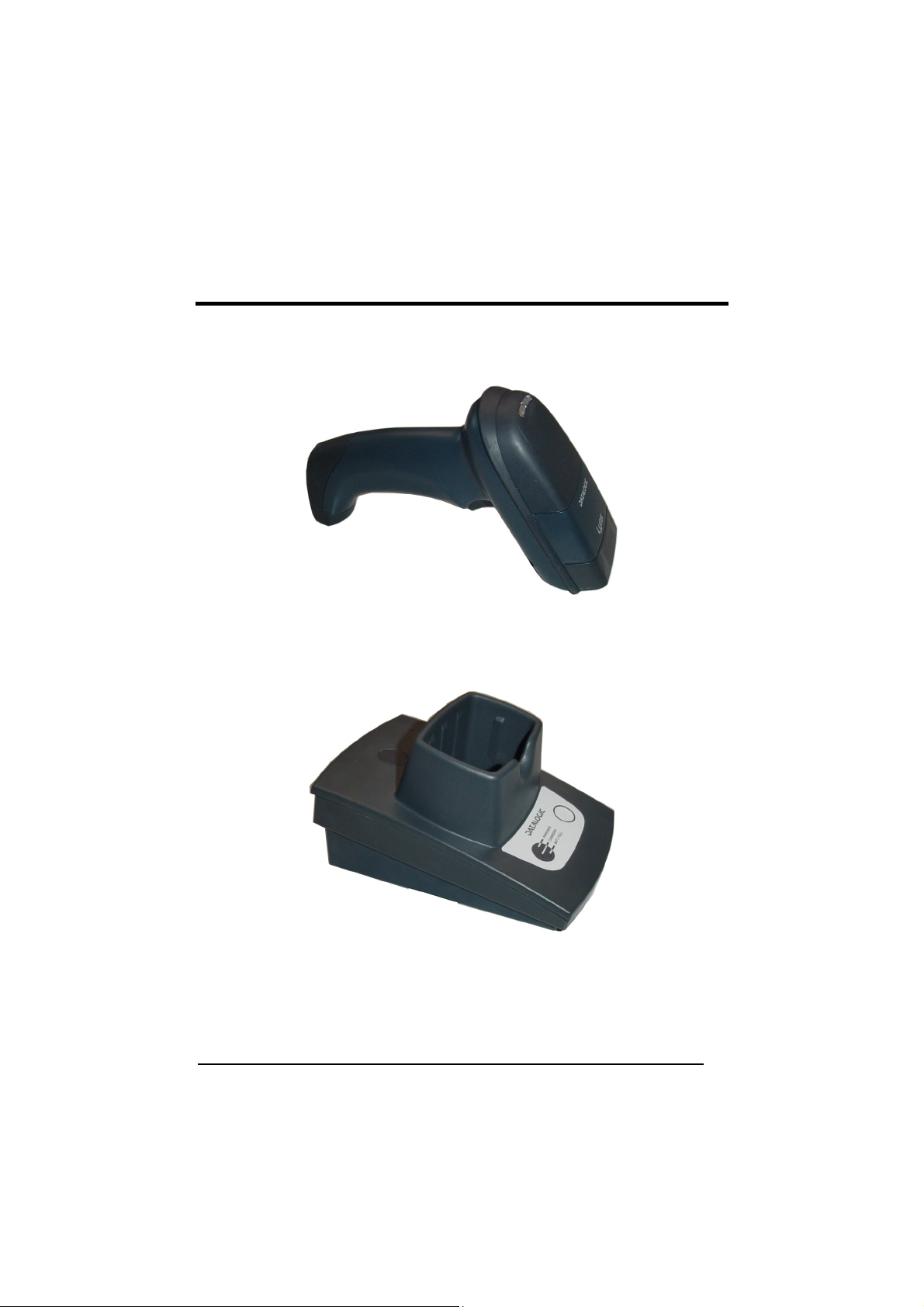
GENERAL VIEW
LYNX™ BT
OM-1000 BT / C-1000
ix
Page 10
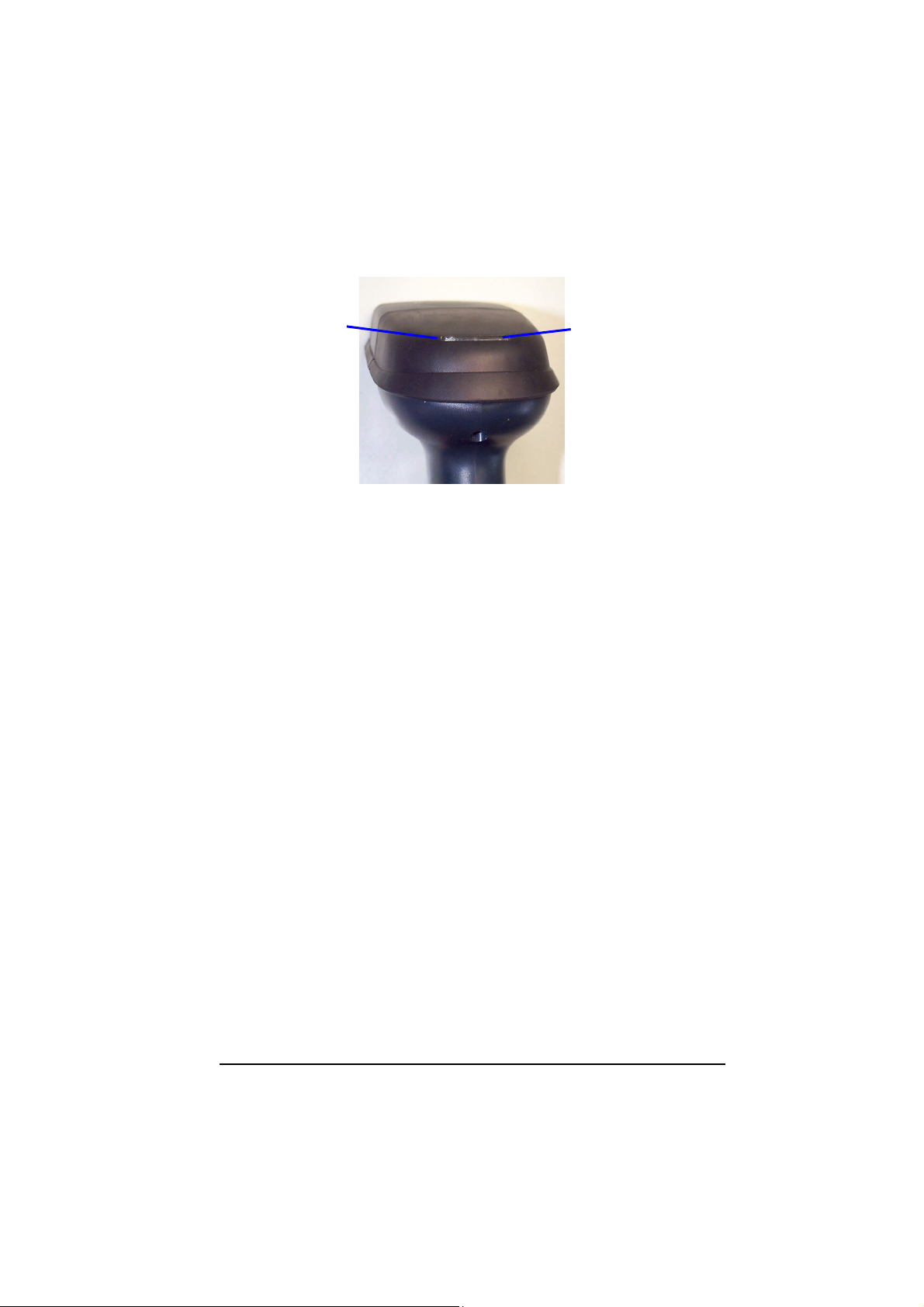
A
iming System ON/
Wrong Read LED
(red)
Good Read LED/
Bluetooth connection
(green)
Lynx™ BT LEDs
x
Page 11
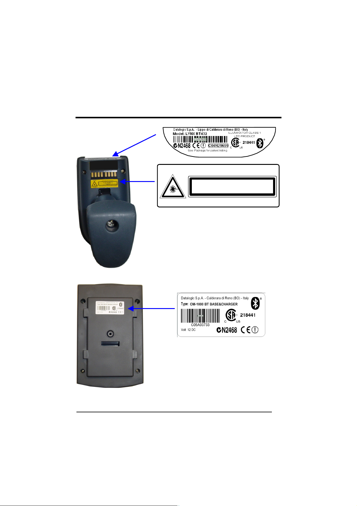
A
COMPLIANCE
DO NOT STARE
INTO BEAM
This product complies with
21 CFR Subchapter J
Lynx™ BT Product Labels
FCC ID: OMJ0012
CAUTION-CLASS 2 LASER LIGHT WHEN OPEN
LASER LIGHT - DO NOT STARE INTO BEAM
MAX. OUTPUT RADIATION 0.25 mW - EMITTED WAVELENGTH 640~660 nm
AVOID EXPOSURE LASER LIGHT IS EMITTED FROM THIS APERTURE
CLASS 2 LASER PRODUCT
TO EN 60825-1:2001
.58
FCC ID: OMJ0011
OM-1000 BT Product Label
xi
Page 12

FCC COMPLIANCE
Modifications or changes to this equipment without the expressed written
approval of Datalogic could void the authority to use the equipment.
This device complies with PART 15 of the FCC Rules. Operation is subject to the
following two conditions: (1) This device may not cause harmful interference, and
(2) this device must accept any interference received, including interference
which may cause undesired operation.
OM-1000 BT
This equipment has been tested and found to comply with the limits for a Class B
digital device, pursuant to part 15 of the FCC Rules. These limits are designed to
provide reasonable protection against harmful interference in a residential
installation. This equipment generates, uses and can radiate radio frequency energy
and, if not installed and used in accordance with the instructions, may cause harmful
interference to radio communications. However, there is no guarantee that
interference will not occur in a particular installation. If this equipment does cause
harmful interference to radio or television reception, which can be determined by
turning the equipment off and on, the user is encouraged to try to correct the
interference by one or more of the following measures:
- Reorient or relocate the receiving antenna.
- Increase the separation between the equipment and receiver.
- Connect the equipment into an outlet on a circuit different from that to which the
receiver is connected.
- Consult the dealer or an experienced radio/TV technician for help.
RADIO COMPLIANCE
Contact the competent authority responsible for the management of radio frequency
devices of your country to verify the eventual necessity of a user license.
Refer to the web site http://europa.eu.int/comm/enterprise/rtte/spectr.htm for further
information.
WEEE COMPLIANCE
xii
Page 13
LASER SAFETY
The Lynx™ BT hand-held reader is a Class 1 LED product regarding its Illuminator
and a Class 2 laser product regarding its Aiming System.
LED Illuminator
The use of an illuminator in the Lynx™ BT hand-held reader is a Class 1 LED
product:
ILLUMINATORE LED CLASSE 1
AUSLEUCHTER LED KLASSE 1
ILLUMINATEUR A LED DE CLASSE 1
ILUMINADOR LED DE CLASE 1
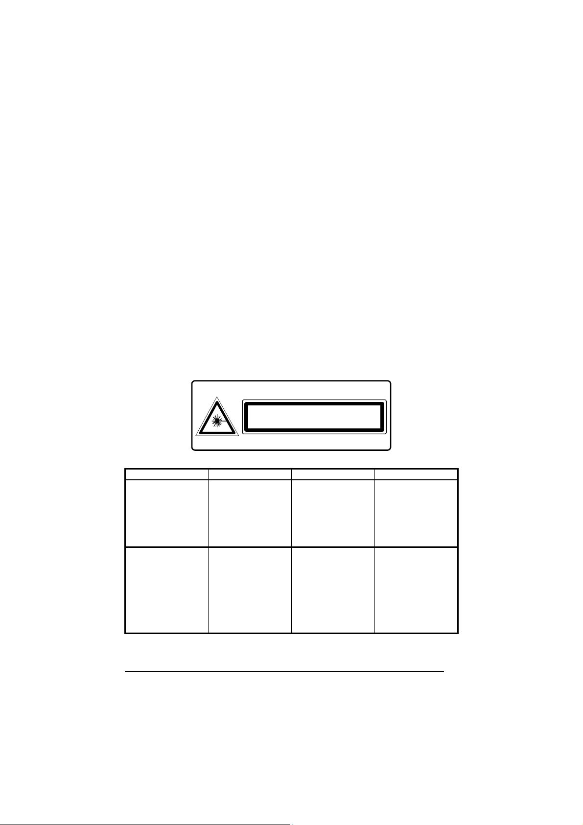
Aiming System
The Lynx aiming system meets the requirements for laser safety.
LA LUCE LASER È
VISIBILE ALL'OCCHIO
UMANO E VIENE
EMESSA DALLA
FINESTRA INDICATA
NELLA FIGURA.
LUCE LASER NON
FISSARE IL FASCIO
APPARECCHIO LASER
DI CLASSE 2 MASSIMA
POTENZA D'USCITA:
LUNGHEZZA D'ONDA
EMESSA:
CONFORME A EN
60825-1 (2001)
DO NOT STARE
INTO BEAM
This product complies with
21 CFR Subchapter J
CAUTION-CLASS 2 LASER LIGHT WHEN OPEN
LASER LIGHT - DO NOT STARE INTO BEAM
MAX. OUTPUT RADIATION 0.25 mW - EMITTED WAVELENGTH 640~660 nm
AVOID EXPOSURE LASER LIGHT IS EMITTED FROM THIS APERTURE
CLASS 2 LASER PRODUCT
TO EN 60825-1:2001
I D F E
DIE LASERSTRAHLUNG IST FÜR
DAS MENSCHLICHE
AUGE SICHTBAR UND
WIRD AM STRAHLAUSTRITTSFENTSTER
AUSGESENDET
(SIEHE BILD)
LASERSTRAHLUNG
NICHT IN DEN STRAHL
BLICKEN PRODUKT
DER LASERKLASSE 2
MAXIMALE
AUSGANGSLEISTUNG:
WELLENLÄGE:
ENTSPR. EN 60825-1
(2001)
LE RAYON LASER EST
VISIBLE À L'OEIL MU
ET IL EST ÉMIS PAR
LA FENÊTRE
DÉSIGNÉE SUR
L'ILLUSTRATION DANS
LA FIGURE
RAYON LASER EVITER
DE REGARDER LE
RAYON APPAREIL
LASER DE CLASSE 2
PUISSANCE DE
SORTIE:
LONGUER D'ONDE
EMISE:
CONFORME A EN
60825-1 (2001)
A LUZ LÁSER ES
VISIBLE AL OJO
HUMANO Y ES
EMITIDA POR LA
VENTANA INDICADA
EN LA FIGURA.
RAYO LÁSER NO
MIRAR FIJO EL RAYO
APARATO LÁSER DE
CLASE 2 MÁXIMA
POTENCIA DE SALIDA:
LONGITUD DE ONDA
EMITIDA:
CONFORME A EN
60825-1 (2001)
xiii
Page 14
ENGLISH
The following information is provided to comply with the rules imposed by
international authorities and refers to the correct use of your terminal.
STANDARD LASER SAFETY REGULATIONS
This product conforms to the applicable requirements of both CDRH 21 CFR 1040
and EN 60825-1 at the date of manufacture.
For installation, use and maintenance, it is not necessary to open the device.
Use of controls or adjustments or performance of procedures other
than those specified herein may result in exposure to hazardous
WARNING
visible laser light.
The product utilizes a low-power laser diode. Although staring directly at the laser beam
momentarily causes no known biological damage, avoid staring at the beam as one
would with any very strong light source, such as the sun. Avoid that the laser beam hits
the eye of an observer, even through reflective surfaces such as mirrors, etc.
ITALIANO
Le seguenti informazioni vengono fornite dietro direttive delle autorità internazionali e
si riferiscono all’uso corretto del terminale.
NORMATIVE STANDARD PER LA SICUREZZA LASER
Questo prodotto risulta conforme alle normative vigenti sulla sicurezza laser alla data
di produzione: CDRH 21 CFR 1040 e EN 60825-1.
Non si rende mai necessario aprire l’appa-recchio per motivi di installazione, utilizzo
o manutenzione.
L'utilizzo di procedure o regolazioni differenti da quelle descritte
nella documentazione può provocare un'esposizione pericolosa
ATTENZIONE
a luce laser visibile.
Il prodotto utilizza un diodo laser a bassa potenza. Sebbene non siano noti danni
riportati dall’occhio umano in seguito ad una esposizione di breve durata, evitare di
fissare il raggio laser così come si eviterebbe qualsiasi altra sorgente di luminosità
intensa, ad esempio il sole. Evitare inoltre di dirigere il raggio laser negli occhi di un
osservatore, anche attraverso superfici riflettenti come gli specchi.
xiv
Page 15
DEUTSCH
Die folgenden Informationen stimmen mit den Sicherheitshinweisen überein, die von
internationalen Behörden auferlegt wurden, und sie beziehen sich auf den korrekten
Gebrauch vom Terminal.
NORM FÜR DIE LASERSICHERHEIT
Dies Produkt entspricht am Tag der Herstellung den gültigen EN 60825-1 und CDRH
21 CFR 1040 Normen für die Lasersicherheit.
Es ist nicht notwendig, das Gerät wegen Betrieb oder Installations-, und Wartungsarbeiten zu öffnen.
Jegliche Änderungen am Gerät sowie Vorgehensweisen, die nicht
in dieser Betriebsanleitung beschreiben werden, können ein
ACHTUNG
gefährliches Laserlicht verursachen.
Der Produkt benutzt eine Laserdiode. Obwohl zur Zeit keine Augenschäden von
kurzen Einstrahlungen bekannt sind, sollten Sie es vermeiden für längere Zeit in den
Laserstrahl zu schauen, genauso wenig wie in starke Lichtquellen (z.B. die Sonne).
Vermeiden Sie es, den Laserstrahl weder gegen die Augen eines Beobachters, noch
gegen reflektierende Oberflächen zu richten.
FRANÇAIS
Les informations suivantes sont fournies selon les règles fixées par les autorités
internationales et se réfèrent à une correcte utilisation du terminal.
NORMES DE SECURITE LASER
Ce produit est conforme aux normes de sécurité laser en vigueur à sa date de
fabrication: CDRH 21 CFR 1040 et EN 60825-1.
Il n’est pas nécessaire d’ouvrir l’appareil pour l’installation, l’utilisation ou l’entretien.
L'utilisation de procédures ou réglages différents de ceux donnés
ici peut entrainer une dangereuse exposition à lumière laser
ATTENTION
visible.
Le produit utilise une diode laser. Aucun dommage aux yeux humains n’a été
constaté à la suite d’une exposition au rayon laser. Eviter de regarder fixement le
rayon, comme toute autre source lumineuse intense telle que le soleil. Eviter aussi
de diriger le rayon vers les yeux d’un observateur, même à travers des surfaces
réfléchissantes (miroirs, par example).
xv
Page 16
ESPAÑOL
Las informaciones siguientes son presentadas en conformidad con las disposiciones
de las autoridades internacionales y se refieren al uso correcto del terminal.
NORMATIVAS ESTÁNDAR PARA LA SEGURIDAD LÁSER
Este aparato resulta conforme a las normativas vigentes de seguridad láser a la
fecha de producción: CDRH 21 CFR 1040 y EN 60825-1.
No es necesario abrir el aparato para la instalación, la utilización o la manutención.
La utilización de procedimientos o regulaciones diferentes de
aquellas describidas en la documentación puede causar una
ATENCIÓN
exposición peligrosa a la luz láser visible.
El aparato utiliza un diodo láser a baja potencia. No son notorios daños a los ojos
humanos a consecuencia de una exposición de corta duración. Eviten de mirar fijo el
rayo láser así como evitarían cualquiera otra fuente de luminosidad intensa, por
ejemplo el sol. Además, eviten de dirigir el rayo láser hacia los ojos de un
observador, también a través de superficies reflectantes como los espejos.
This device must be opened by qualified personnel only.
The Lynx™ BT Hand-Held Reader is not user-serviceable. Opening
the case of the unit can cause internal damage and will void the
CAUTION
warranty.
OM-1000 BT POWER SUPPLY
This device is intended to be supplied by a UL Listed or CSA Certified Power Unit
marked "Class 2" or "LPS" output rated 12 V, minimum 0.75 A which supplies power
directly to the unit via the jack connector.
BLUETOOTH® APPROVAL
This product is equipped with the following certified Bluetooth module:
Product Name Bluetooth ID
Panasonic Serial Port Module B01839
xvi
Page 17

INTRODUCTION
1
1 INTRODUCTION
1.1 LYNX™ BT DESCRIPTION
The Lynx™ BT Hand-Held Reader packs a lot of performance into an attractive,
rugged, hand-held device. It operates in commercial and industrial environments as
well as the front office.
Omnidirectional
Operating
Decoding
FLASH MEMORY
Lynx™ BT communicates in the 2.4 GHz ISM band and uses the Serial Port Profile
(SPP). Thanks to a Bluetooth® device, such as a Bluetooth® dongle, the reader can
send data to a remote Host such as a PC, PDS, printer, etc.
The OM-1000 BT cradle is provided in the package to build a Cordless Reading
System for the collection, decoding and transmission of barcoded data. It can be
connected to a Host PC through a USB, RS232 or Wedge emulation cable. The
OM-1000 BT also allows charging the Lynx™ BT batteries.
To read a symbol you simply aim the reader and pull the
trigger. Since the orientation of the symbol is not important, the
Lynx™ reader is a powerful, omni-directional device.
Thanks to powerful algorithms, Lynx™ reliably decodes all major
1D (linear) barcodes, 2D stacked codes (such as PDF417), 2D
matrix symbols (such as DataMatrix), postal codes (such as
POSTNET, PLANET). The data stream — acquired from
decoding a symbol — is rapidly sent to the host. The reader is
immediately available to read another symbol.
Flash technology allows to upgrade the Lynx™ reader as new
symbologies are supported or as improved decoding
algorithms become available.
1
Page 18
1
LYNX™ BT
1.2 LYNX™ BT BATTERIES
To begin using your Lynx™ BT you must charge its batteries using the OM-1000 cradle
or the C-1000 battery charger as described in the following paragraph. You can install
Li-Ion batteries in the Lynx™ BT.
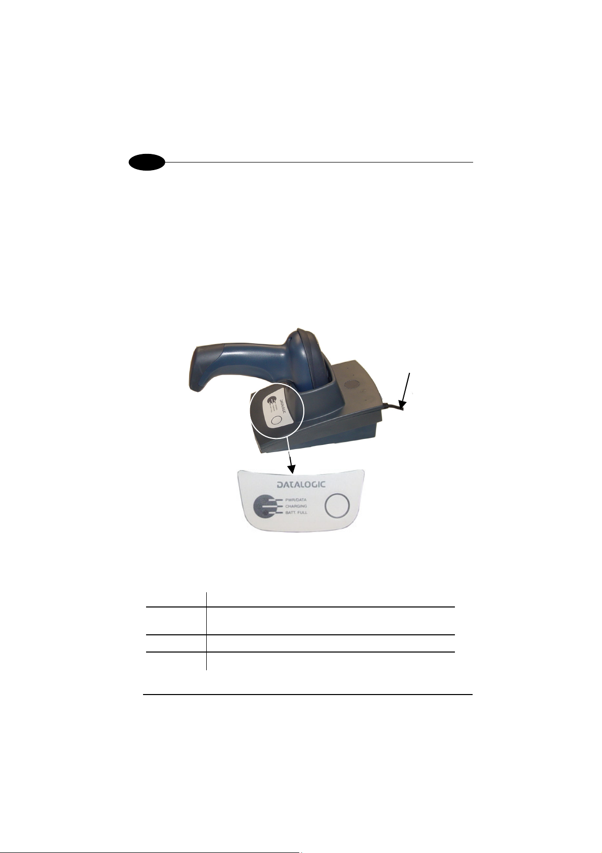
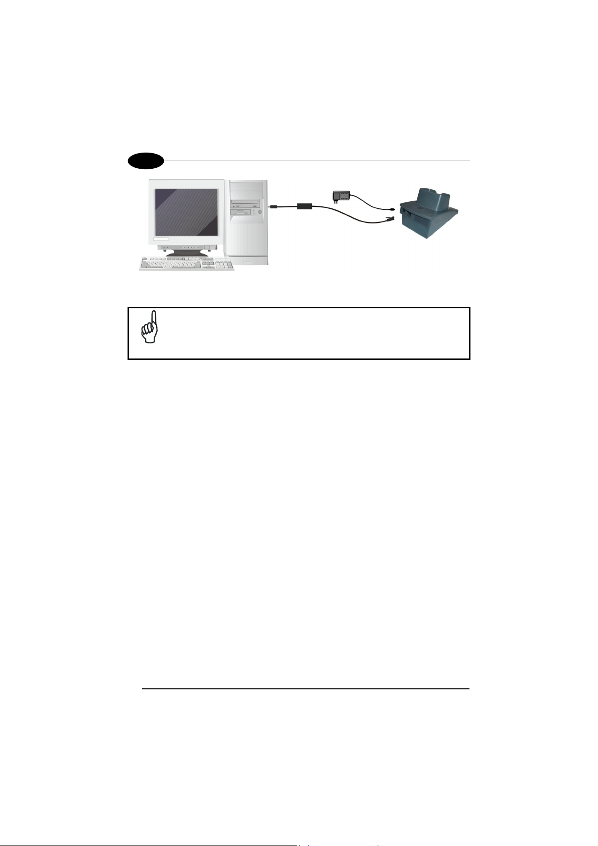
Battery Charging
The first operation to perform is to connect the OM-1000 or the C-1000 to the power
converter and firmly insert the Lynx™ BT into the cradle to charge the batteries. The
red Charging LED will light. A full charge takes about 3.5 hours. The Batt. Full LED will
light when charging is completed. Press the reader trigger to turn it on.
Power Cable
Figure 1 – OM-1000 BT Charging Batteries
The LEDs positioned on the cradle signal the status, as described in the following
table:
LED STATUS
Pwr/Data Yellow On = cradle is powered
Yellow Blinking = cradle receives commands from Host
Charging Red On = the battery charge is in progress
Batt Full Green On = the battery is completely charged
2
Page 19
INTRODUCTION
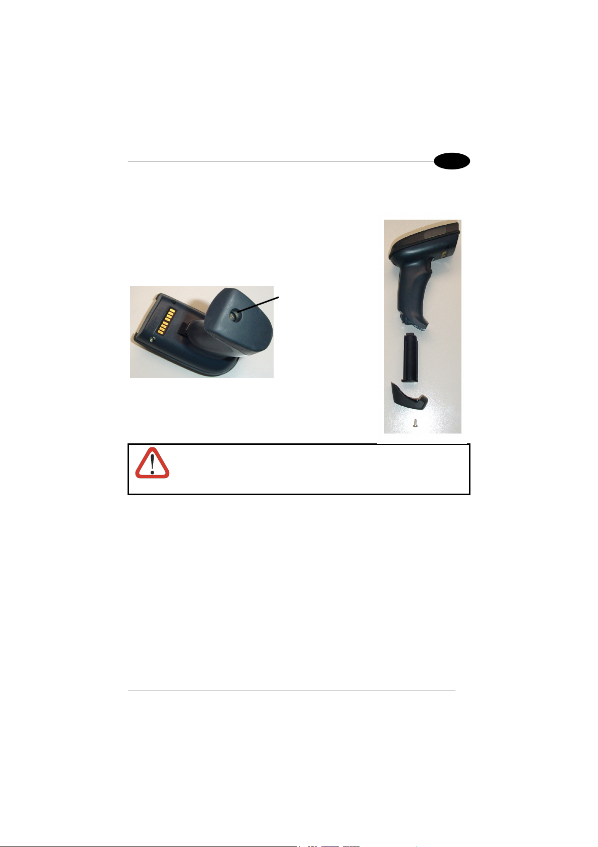
Replacing Lynx™ BT Batteries
To change the batteries in the Lynx™ BT, unscrew the
battery cover screw, replace the old battery pack with a
new one of the same type, then insert the cover onto the
handle and screw it back into place. See the following
figures.
To turn on the reader, press the trigger.
Battery Cover Screw
1
Risk of explosion if the battery is replaced by an incorrect
type. Dispose of the batteries as required by the relevant laws
WARNING
in force.
1.3 CONFIGURATION METHODS
1.3.1 Reading Configuration Barcodes
This manual can be used for complete setup and configuration. If you wish to change
the default settings, you can configure the Lynx™ BT reader by reading the
programming barcode symbols in this manual. Configuration commands and their
relative arguments are read individually using the symbols in this manual. See
chapter 4, and Appendix C.
3
Page 20

1
LYNX™ BT
1.3.2 Using VisualSetup
The Datalogic VisualSetup program, available on the CD-ROM provided, allows
programming the reader by selecting configuration commands or printing them
through a user-friendly graphical interface running on the PC. These commands are
sent to the reader over the current communication interface; or they can be printed to
be read.
1.4 BLUETOOTH
Bluetooth® address: a unique 12-character hexadecimal, IEEE 48-bit
Bluetooth
Bluetooth® device: a device that is capable of short-range wireless
BT: abbreviation for Bluetooth®. Bluetooth® protocol is a
Remote Bluetooth
SPP: Serial Port Profile. Bluetooth
Master: the first Bluetooth
Slave: a Bluetooth
User-Friendly name: a human-readable name to set for a Lynx™ BT to
Piconet: Bluetooth® device network where a Master can
For further information about Bluetooth technology see the website:
®
controller: a sub-system containing Bluetooth® RF, baseband,
®
DEFINITIONS
address (BT_ADDR) that represents a Bluetooth
device.
resource controller, link manager, device manager,
and Bluetooth
communication using the Bluetooth
®
HCI.
®
system.
predefined rule that sets out a specific system for
devices to communicate with each other and a
protocol stack is the layering of the protocols that are
used in a specific technology. The Bluetooth
®
Radio
protocol operates in the 2.4GHz ISM band.
®
device: any Bluetooth® device the reader can communicate
with.
®
profile creating an
RS232 cable replacement.
®
device initiating the radio
connection (Discovery procedure).
®
device which can only wait for a
Bluetooth
®
Master device to initiate a connection with
it.
make it easily recognizable when operating together
with other Bluetooth
®
devices.
communicate with up to 7 Slaves.
https://www.bluetooth.org/
®
4
Page 21

INSTALLATION
2
2 INSTALLATION
Lynx™ Bt can operate according to two different installations:
• Lynx™ BT paired with OM-1000 BT cradle (see par. 2.1);
• Lynx™ BT communicating with a Bluetooth
par. 2.2).
The green LED and / or the beeper always indicate the reader radio connection
status (see par. 10.1):
− the radio connection is signaled by the green LED through a single blink at
regular intervals, while if the reader radio is disconnected the LED emits two
short blinks at regular intervals;
− during the initialization procedure, if the radio connection attempt is successful,
the reader emits four ascending tones;
− the radio disconnection is signaled by four descending tones.
2.1 OPERATING LYNX™ BT WITH OM-1000 BT
To begin using your Lynx™ BT reader you must charge the Lynx™ BT battery
using OM-1000™ BT as described in par. 1.2. A full charge takes about 3.5
hours with Li-Ion batteries.
The Lynx™ BT, paired with an OM-1000 BT cradle, builds a Cordless Reading
System for the collection, decoding and transmission of barcoded data.
®
device as Master or as Slave (see
5
Page 22
2
LYNX™ BT
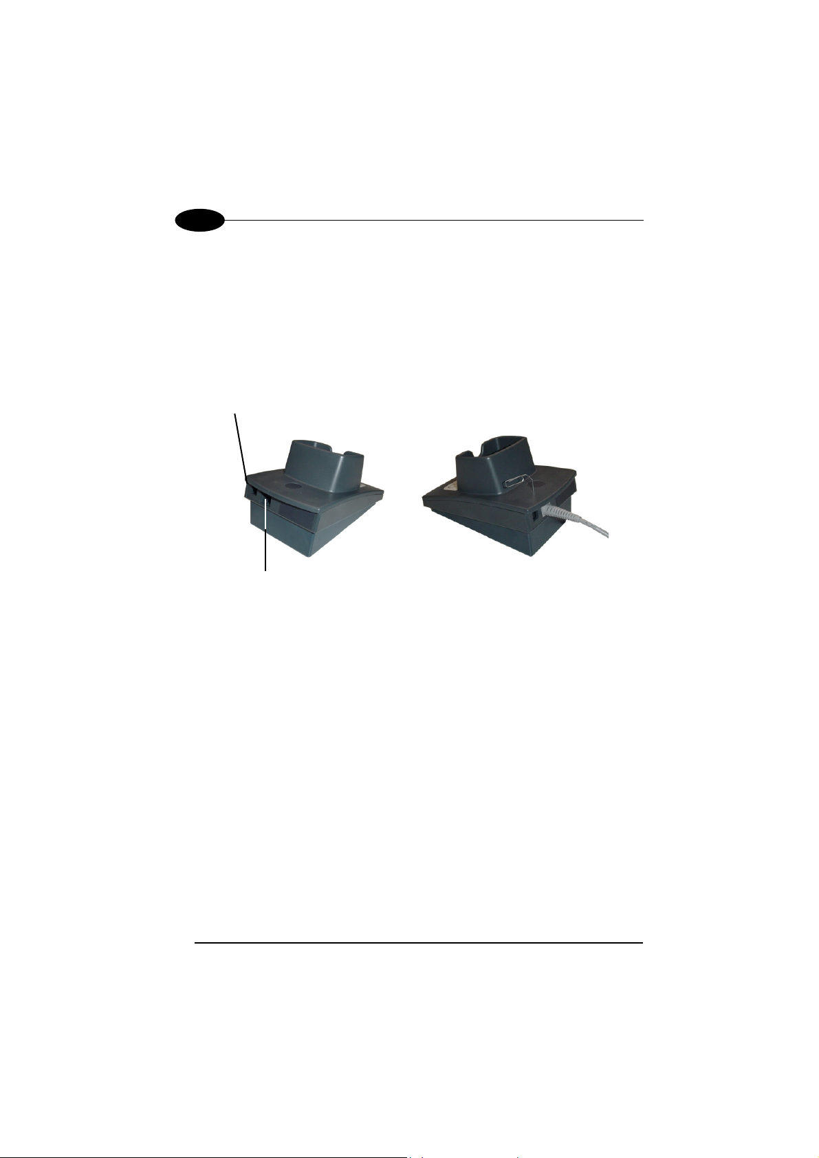
2.1.1 OM-1000 BT Interface Cable Connections
The OM-1000™ can be connected to a Host by means of an RS232, Wedge or USB
cable which must be simply plugged into the Host connector, visible on the rear panel
of the cradle.
To disconnect the cable, insert a paper clip or other similar objects into the hole
corresponding to the Host connector on the body of the cradle. Push down on the clip
while unplugging the cable. Refer to the following figure:
Power
Multi-standard interface
RS232, WEDGE, or USB
to Host
Figure 2 – Connecting/Disconnecting the Cable
6
Page 23
INSTALLATION
2
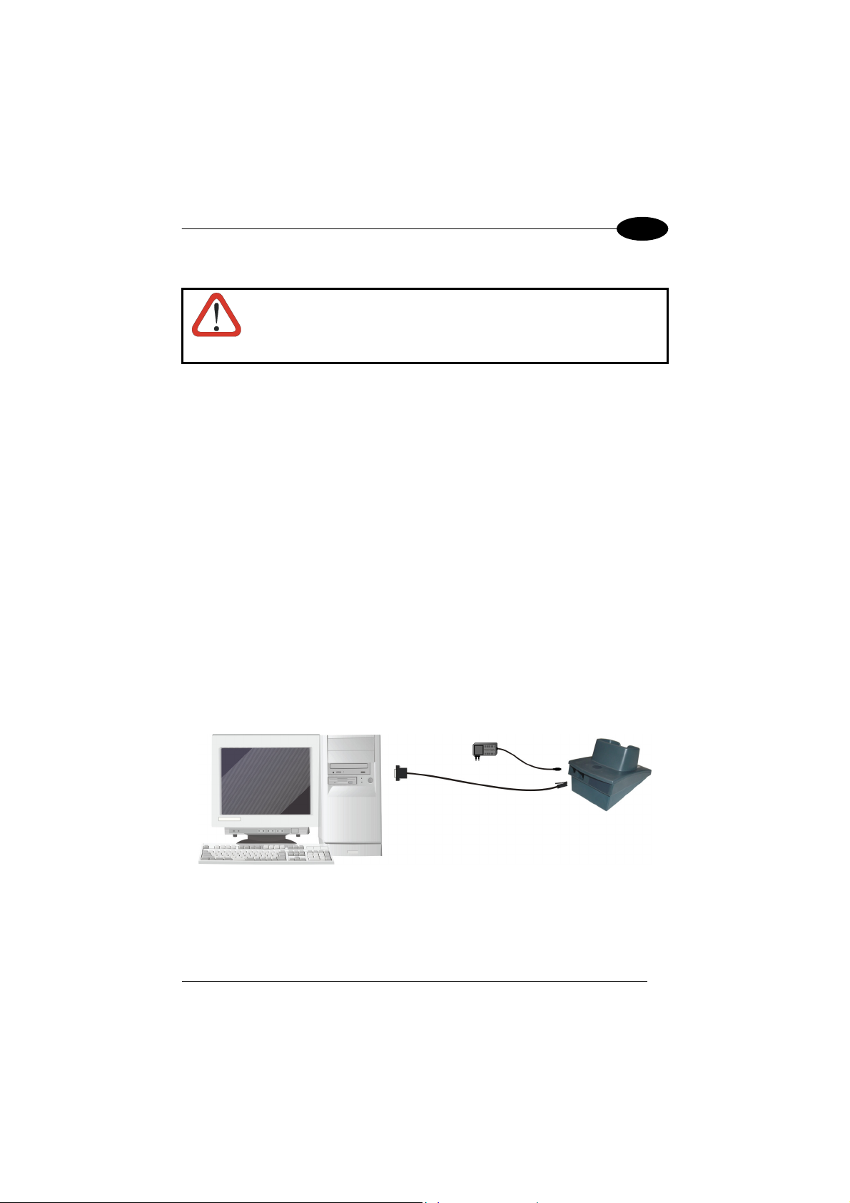
RS232 Connection
Connections should always be made with both PC and Cradle
power off!
CAUTION
The OM-1000 cradle requires the RS232 interface cable and the AC/DC power
adapter to be connected.
To install your cradle to your host system, follow these instructions (see Figure 3
below).
1. After charging the batteries (see par. 1.2), bind the Lynx™ BT to the OM-1000
BT by following the procedure given in par. 4.1.1;
2. Insert the RS232 cable into the OM-1000 cradle;
3. Connect the RS232 interface cable to the proper port on the host terminal;
4. Connect the power cord to the OM-1000 cradle;
5. Connect the AC/DC power adapter at the wall outlet;
6. Upon OM-1000 power up, wait for the series of beeps indicating Bluetooth
connection.
7. Read the RS232 interface code in par. 4.1.1.
8. Power up your PC.
Figure 3 - RS232 Connection
7
Page 24
2
LYNX™ BT
Wedge
Connections should always be made with both PC and Cradle
power off!
CAUTION
The OM-1000 cradle requires the Wedge interface cable and the AC/DC power
adapter to be connected.
To install your cradle to your host system, follow these instructions (see Figure 4
below).
1. After charging the batteries (see par. 1.2), bind the Lynx™ BT to the OM-1000
BT by following the procedure given in par. 4.1.2;
2. Insert the Wedge cable into the OM-1000 cradle;
3. Connect the power cord to the OM-1000 cradle;
4. Connect the AC/DC power adapter at the wall outlet;
5. Upon OM-1000 power up, wait for the series of beeps indicating Bluetooth
connection.
6. BEFORE CONNECTING THE WEDGE CABLE TO THE PC AND KEYBOARD,
read the Wedge IBM AT interface code in par. 4.1.2.
7. Connect the WEDGE interface cable between the keyboard and the host
terminal.
8. Power up your PC.
Wedge AT is the default interface set at the factory.
CAUTION
8
Figure 4 - Wedge Connection
When not using the OM-1000 cradle remember to disconnect the
Wedge interface from the PC before disconnecting the power cord.
Page 25

INSTALLATION
2
It is always necessary to use an external power supply connected to
the OM-1000 cradle.
NOTE
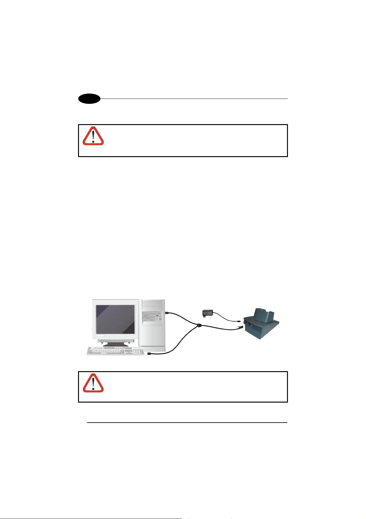
USB Connection
The OM-1000 cradle requires the USB interface cable and the AC/DC power adapter
to be connected.
To install your cradle to your host system, follow these instructions (see Figure 5
below).
1. After charging the batteries (see par. 1.2), bind the Lynx™ BT to the OM-1000
BT by following the procedure given in par. 4.1.3;
2. Insert the USB cable into the OM-1000 cradle;
3. Connect the USB cable to the PC;
4. Connect the power cord to the OM-1000 cradle;
5. Connect the AC/DC power adapter at the wall outlet.
6. Upon OM-1000 power up, wait for the series of beeps indicating Bluetooth
connection.
7. Read the correct USB interface code for your application in par. 4.1.3.
8. Connect the USB interface cable to a free USB port. The PC automatically
recognizes the device and asks to install the device driver.
9. Install the USB driver on your PC (the first time only) to complete the connection.
• For USB COM the relevant files and drivers must be installed from the
USB Device Installation software which can be downloaded from the
web site http://www.datalogic.com
• For USB Keyboard the correct USB driver is included in the Host
Operating System and will either be loaded automatically or will be
suggested by the O.S. and should therefore be selected from the
dialog box.
.
9
Page 26
2
LYNX™ BT
Figure 5 – USB Connection
NOTE
The OM-1000 cradle is a USB self-powered device.
2.2 OPERATING LYNX™ BT WITH BLUETOOTH® DEVICE
During typical operation a physical radio channel is shared by a group of devices that
are synchronized to a common clock and frequency hopping pattern. One device
provides the synchronization reference and is known as the Master. All other devices
are known as Slaves. A group of devices synchronized in this fashion form a piconet.
Most Bluetooth® devices can be both Master or Slave. The Master will be the first unit
to initiate the connection (page procedure).
Some devices can only be Slaves (i.e. printers). They can only wait for a Bluetooth
Master device to initiate a connection with them.
Lynx™ BT can be either Master or Slave. As Master it can initiate a connection with
only one Slave device.
®
10
Page 27

INSTALLATION
2
2.2.1 Lynx™ BT as Slave
Once set as Slave, a Lynx™ BT reader requires no particular configuration for
communication, however some radio parameters can be set to increase system
performance and data transmission security. At startup the reader can only wait for
the Master to initialize the radio communication.
The following is a general procedure recommended for Lynx™ BT Slave
applications:
1. Power up the remote Bluetooth® Master device (example Laptop or PC).
2. Power up the Lynx™ BT reader within radio range (10 meters).
Any modifications to the radio configuration should be made at this time before
the radio connection takes place.
3. From the remote Bluetooth
(according to the procedure given in the documentation of the Bluetooth
device), to recognize the Lynx™ BT reader(s) within radio range.
4. Check that "Lynx BTx00 " is shown among the discovered devices.
5. Request to open an SPP connection with Lynx™ BT, making sure to disable any
required PIN and/or pairing parameters. Lynx™ BT is always discoverable and
connectable without any required PIN.
®
Master device, execute the Discovery procedure,
®
Master
If the PIN of the Bluetooth® Master device cannot be disabled, use the
PIN "1234". The Lynx™ BT Slave will emit four ascending tones
NOTE
indicating radio connection.
After the Lynx™ BT reader(s) indicate radio connection (see also par. 10.1), you can
start sending barcodes.
11
Page 28
2
r
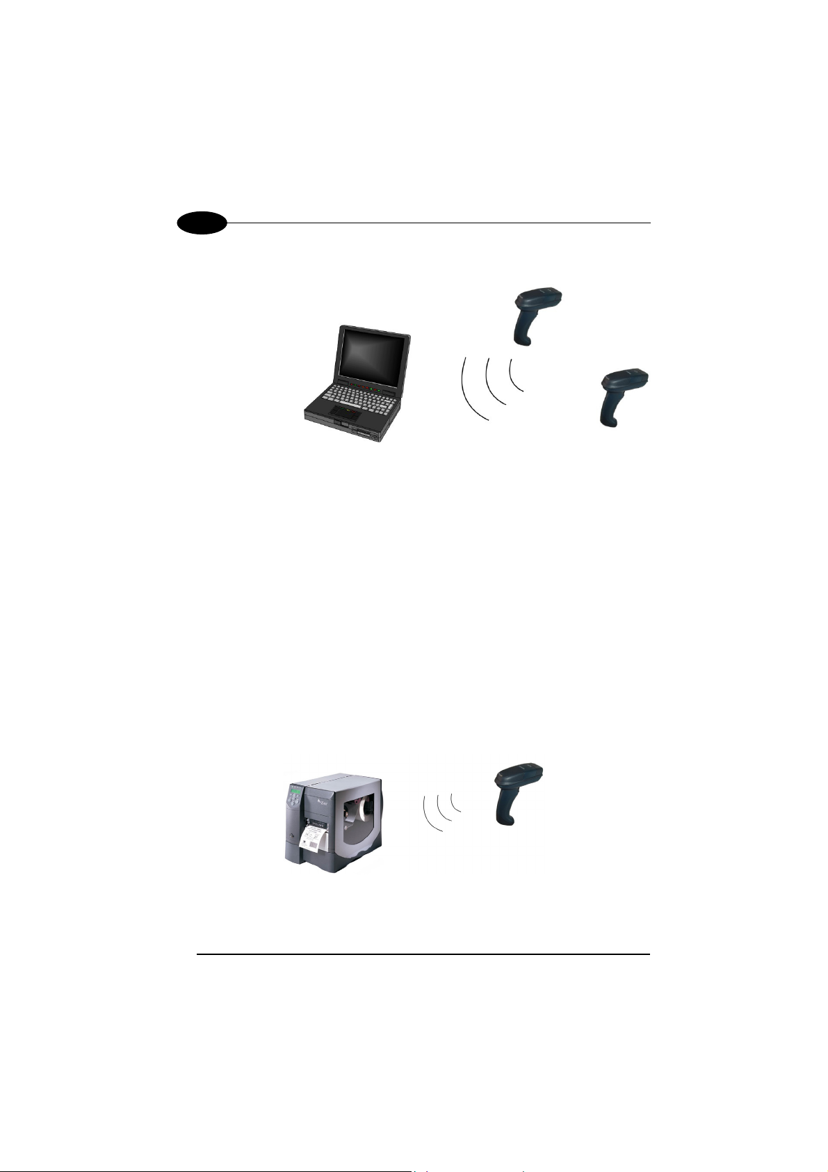
The following figure shows an example Lynx™ BT Slave application.
LYNX™ BT
Master
Slave
Laptop
Lynx™ BT readers
(Bluetooth® device)
Slave
Figure 1 - Lynx™ BT Slave Application
If the Master Bluetooth
®
device can support a piconet, the communication can be
established with up to 7 seven Slave readers at the same time.
2.2.2 Lynx™ BT as Master
Once set as Master, a Lynx™ BT reader must be configured with the address of the
Slave device to which it wants to communicate.
By default, at startup the reader initializes the communication with the Slave. If the
connection is successful, the reader can send barcodes to the Slave device. Radio
connections can also be managed manually as described in pars., Errore. L'origine
riferimento non è stata trovata. and Errore. L'origine riferimento non è stata
trovata..
During the request of radio connection or disconnection with a remote Bluetooth®
Slave device, the reader emits a series of ticks and short blinks of the green LED.
The following figure shows an example Lynx™ BT Master application.
Slave
Master
Lynx™ BT
Barcode Printe
(Bluetooth
12
®
device)
Figure 2 - Lynx™ BT Master Application
Reader
Page 29

INSTALLATION
2
2.2.3 Data Transmission
The transmission of data can be transparent (no ACK/NACK protocol), when each
character is read and immediately sent to the Host (default value). Otherwise, data
transmission can be with flow control (with ACK/NACK protocol), when, after each
reading, Lynx™ BT waits for an acknowledge that the remote Host received the data
before reading and sending the following code.
2.2.4 Wedge Emulation Utility
This utility is provided on the CD-ROM. When using the Wedge Emulation Utility, it is
advised to correctly set the terminators depending on the expected format for the
program in which the data will be collected.
13
Page 30
3
LYNX™ BT
3 USING LYNX™ BT
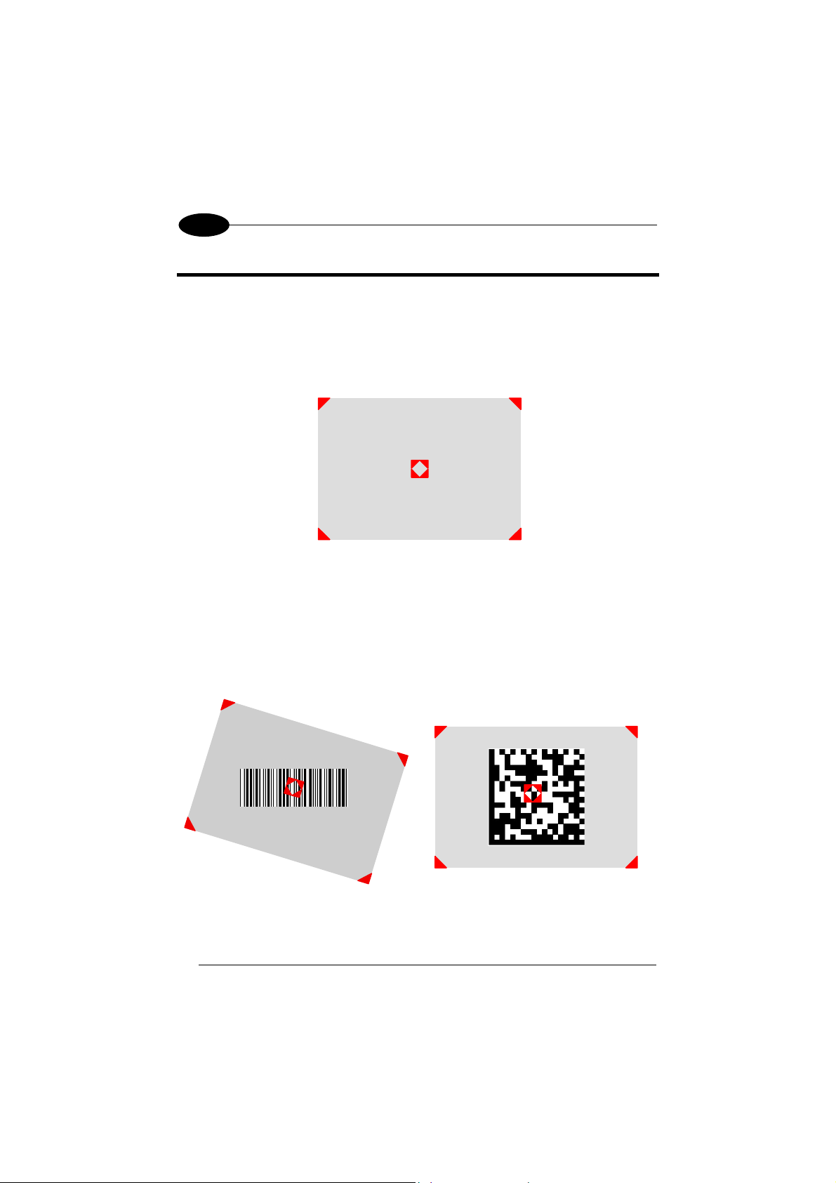
3.1 AIMING SYSTEM
The LYNX™ reader uses an intelligent aiming system similar to those on cameras.
The aiming system creates a field of view where the code is to be positioned:
Figure 6 - Aiming System
When you pull the trigger completely a red beam illuminates the code. If the aiming
system is centered and the entire symbology is within the aiming system, you will get
a good read. The field of view changes size as you move the reader closer or farther
away from the code.
Linear barcode 2D Matrix symbol
14
Figure 7 - Relative Size and Location of Aiming System Pattern
Page 31

USING LYNX™ BT
3
The field of view created by the aiming system will be smaller when the Lynx™ is
closer to the code and larger when it is farther from the code. Symbologies with
smaller bars or elements (mil size) should be read closer to the unit. Symbologies
with larger bars or elements (mil size) should be read farther from the unit. (See
chapter 7 for further details).
3.2 NORMAL OPERATION
Lynx™ normally functions by capturing and decoding codes.
Point the reader at the target and pull the trigger partially to enable the aiming
system. Then, pull it completely to capture and decode the image. The reader will
repeatedly flash until the symbol is decoded or timeout is reached. In between the
flashes of the reader, the aiming system keeps on showing the field of view on the
target (see Figure 7
).
As you are reading code symbols, adjust the distance at which you are holding the
reader.
The LYNX™ hand-held reader aiming system is designed for general
reading and decoding of 1D and 2D symbols. Some variation in
NOTE
reading distance will occur due to narrow bar width and other factors.
3.3 IMAGE CAPTURING
Lynx™ can also function as a camera by capturing images of labels, signatures, and
other items.
In order to capture an image, the user should read a Capture Image code (see par
0), then point at the image subject and pull the trigger. This way, the image will be
captured and sent to the host PC. Lynx™ then returns to normal operation. To
capture another image you must read another Capture Image Code of the same or a
different Preset Configuration.
You can use the aiming system to position the reader from the object (ensure the
reader is about centered over the target). Adjust the distance at which you are
holding the reader (see Figure 7).
If the RS232 interface has been selected, the image will be transferred to the host
PC via XMODEM_1K protocol.
15
Page 32

3
LYNX™ BT
Image capturing is not available in Wedge and USB Keyboard
Emulation interfaces and is not compatible with Autoscanning nor
NOTE
when the Software trigger type is selected.
Up to four different and independent Image Presets can be defined (see par. 0).
For each Image Preset you may set up to three Basic Configuration Parameters, and
up to five Advanced Configuration Parameters. Therefore an image is processed
before being sent to the Host, according to a preset group of parameters.
3.3.1 Basic Configuration Parameters
The Image file formats supported are: BMP, TIFF, JPEG (default).
Two resolution options are available: VGA Resolution (640 x 480 pixels) (default),
and CIF Resolution (320 x 240 pixels). The lower resolution setting yields smaller file
sizes, so the transfer time decreases.
For JPEG images it is possible to define the Image Quality level to address tradeoff
between image file size and quality.
16
Page 33

USING LYNX™ BT
3
3.3.2 Advanced Configuration Parameters
An image portion (Window), instead of an entire image, can be captured. This
parameter is generally used for particular fixed reading position applications.
0
Y
0
X0
height
width
480
Y
An Image Window may either be as large as the image itself or smaller (10 x 10
pixels minimum), and is defined by its origin (the coordinate X
), its width (number
0, Y0
of pixels along the X Axis) and its height (number of pixels along the Y Axis).
By default, for all Image Presets, the window has its origin coordinates equal to zero,
its width equal to 640 pixels and its height to 480 pixels.
It is possible to perform Zooming of the image. The zoom range varies from 20% up
to 200% in steps of 20%, so ten different settings are available. Default is 100% (no
zoom).
In addition to Windowing and Zoom you can adjust Brightness and Contrast levels.
Brightness Adjustment is available in the range from –100% up to 100%, in steps of
1%. Positive values shift the luminance up so that the image will result brighter.
Default value is 0%, meaning that no brightness adjustment is performed.
640
X
17
Page 34

3
The same range of values (–100% up to 100%, in steps of 1%) is available for
Contrast Adjustment. Positive values will increase the contrast, so that dark and
bright objects inside the image will be better distinguishable. Default value is 0%,
which means that no contrast adjustment is performed.
You can set the Image Color Depth by selecting 256 gray levels (default), 16 gray
levels, or 2 gray levels. Higher color depths yield larger image files. This option is
ignored if the JPEG format is selected,(256 gray levels only).
LYNX™ BT
3.4 AUTOSCANNING
3.4.1 Normal Mode
Lynx™ provides an autoscan command (see par. 0), which when enabled, causes
the reader to scan continuously and to monitor the central zone of its reading area. In
this way, Lynx™ is ready to capture any image (containing a potential code)
positioned on a uniform background.
The aiming system can be enabled to indicate the reading area of the potential code
to be captured. The illumination system can also be enabled when the ambient light
conditions are not sufficient to autodetect the potential code to be captured;
furthermore, the illumination system increases in intensity for an instant when
capturing and decoding an image. A safety time may be defined to prevent Lynx™
from reading the same code repeatedly.
If the decoding is completed successfully, the reader starts monitoring the reading
area again. In case of decoding failure, Lynx™ keeps on decoding until a potential
code is present in the central zone of the reading area.
3.4.2 Pattern Mode
The Autoscan pattern mode is particularly advised when reading barcodes positioned
on a non-uniform background. In these cases Lynx™ may perceive some elements
of the background as barcodes and start the decoding. To avoid this undesired
effect, the Autoscan Pattern Code is placed in the Lynx™ reading area which
prevents decoding. Using this code as the background, code reading takes place
normally by presenting desired codes to be read over the Pattern Code. Between
each code read, the Pattern Code must be represented to Lynx™.
The Pattern Code can be printed from the file of the manual (Appendix C) available
on the CD-ROM.
In case of low ambient light conditions, Lynx™ automatically activates the
illumination system. If desired, the illumination system can be enabled so that it is
always active.
18
Page 35

USING LYNX™ BT
3
3.5 CAMERA CONTROL
Exposure and Calibration
Two different control modes are available for managing the camera: automatic mode
and fixed mode.
The automatic mode provides three different options to get the best tuning of the
image to be captured:
- Automatic based on entire image
the whole image. This mode works well in most standard applications. It is the
default setting.
- Automatic based on central image
of a restricted area positioned in the central zone of the image. This mode is
suggested when reading small codes positioned in a dark and extensive
background.
- Automatic for highly reflective surfaces
codes on highly reflective surfaces. This mode is suggested, for example, when
reading codes positioned on plastic or metal surfaces.
The fixed mode is particularly suggested for expert users. It requires a camera
calibration to adjust the acquisition parameters to the ambient light conditions. The
defined values will always be used when working with a fixed exposure.
These values are permanently saved in the reader memory.
Refer to par. 0 for configuration barcodes.
Aiming System Calibration
The factory-defined Lynx™ aiming system is already correctly and precisely
calibrated to the Lynx™ focus distance and therefore works for the most typical
applications. However, it is possible to modify the aiming system precision for the
following condition:
when a fixed reading distance different from the Lynx™ focus distance is used.
The Lynx™ focus distance is 115 mm for Lynx™ D432, and 65 mm for Lynx™
D432E.
Refer to the VisualSetup software program for performing the aiming system
calibration.
: camera control mode based on the analysis of
: camera control mode based on the analysis
: camera control mode allowing to read
19
Page 36

3
LYNX™ BT
3.6 DEFINING DATA FORMATTING
Headers and terminators can be set for both cradle and reader. If
working with a Lynx™ BT paired with an OM-1000, the cradle
headers and terminators have the priority while the reader’s ones
CAUTION
The string of a decoded code to be sent to the host may be formatted as follows:
• defining simple data formatting (see “Data Format” in par. 5.1);
• defining advanced data formatting giving complete flexibility in changing the
format of data (see par. 5.2).
When both simple and advanced data formatting are selected the info is processed in
the following order:
1. the string of the decoded code is processed according to the advanced
formatting rules;
2. the resulting string is processed according to the selection type rules of the
simple data formatting;
3. character substitution is performed on the resulting string;
4. character deletion is performed on the resulting string;
5. code concatenation is performed;
6. code ID is attached to the resulting string;
7. global headers and terminators are attached to the resulting string;
The codes to be sent to the host may also be selected or ordered depending on the
following two conditions:
• one code per scan: Lynx™ sends the code being closest to the image center. If
the "Central Code Transmission" command is enabled, only the code containing
the image center will be transmitted (see “Reading Parameters” in par. 5.1);
• all codes per scan: the codes to be sent to the host may be ordered either by
length or by symbology starting from the code being closest to the image center
(see par. “Reading Parameters” in par. 5.1). When enabling both these criteria,
codes belonging to the same symbology are sent to the host depending on their
length.
are ignored (refer to par. 5.1 and par. 6.1.1).
20
Page 37

USING LYNX™ BT
3
3.6.1 Concatenation
It is possible to concatenate up to 4 different codes, set their length and enable the
intercode delay between them (the intercode delay is set in the specific interface
parameters in pars. 5.1). When enabling the delay one or more global headers and
terminators are added to the decoded data. The concatenation procedure may occur
in different ways depending on the number of codes to be decoded per image:
One Code Per Scan
• If the code resulting from the single decoding of an image belongs to one of the
code families to be concatenated, it is saved to the Lynx™ memory waiting for
other codes to complete the concatenation.
• If the code belongs to the same family of a code previously saved, it overwrites
the old one.
• If the code resulting from the decoding does not belong to one of the code
families to be concatenated, it causes the concatenation failure and clears the
temporary memory. If the "Concatenation Failure Transmission" command is set
to "Tx codes causing failure", this code will be sent in the output message.
All Codes Per Scan
• All codes resulting from the decoding of an image and belonging to one of the
families to be concatenated are saved to the Lynx™ memory waiting for other
codes to complete the concatenation.
• If one or more codes resulting from the decoding belong to the same family of
codes previously saved, they overwrite the old ones.
When the image contains no code to be concatenated, the concatenation fails and
the reader temporary memory is cleared. If the "Concatenation Failure Transmission"
command is set to "Tx codes causing failure", the codes causing the concatenation
failure will be sent in the output message.
21
Page 38

4
LYNX™ BT
4 INITIAL SETUP
This procedure allows setting up the reader to operate with the default settings.
Two different procedures are available according to the type of application you are
working with:
− Lynx™ BT paired to the OM-1000 BT (follow procedure in par. 4.1);
− Lynx™ BT communicating with a Bluetooth
par. 4.2).
Whenever you need to change the default values refer to par. 5.1.
4.1 SETTING UP LYNX™ BT WITH OM-1000 BT
Follow the given procedure to make Lynx™ BT communicating with OM-1000 BT.
Read the restore default parameters code below.
1.
Restore Lynx™ BT Default
Read the Bind code to pair the Lynx™ BT to the OM-1000 BT cradle.
2.
The reader is dedicated to the cradle. Any previously bound reader will be
excluded.
The green LED on the Lynx™ BT will blink; the reader is ready to be inserted
into the cradle.
AMHKGPAOFNGNENEIEPANHOGOCK
AHHPMBAMDKEOFMHMLJALECHGIK
AKCBPJCJGIIJCMCFGPLCMMMNLK
AEFBJLBGMHPKMOGNKKNDPDMGGK
AAPHBAJIDGHPOJKEFPNCEACBHK
AFKFBKNGLGMOMELLGOPCMJFKIK
DDDDLDLLLDDLLLLDDDLDDLDLDL
Bind
AMHOHMFOFNGNENEIEPANHOGOCK
AHPHIJAMDKEOFMHMLJAKFEDGJK
AKCBPJCJGIIJCMCFHKKMEFDFPK
AEFBJLBGMHPLNMDKEBJBKCFFGK
AAPHBAJJCGEBADDAMPPMNPNBDK
AEKFAOMIPLKAKPFHGDMOEGDLIK
DDDLLLLDLDDLLLLDLLLDDLDLLL
®
device (follow procedure in
22
Page 39

INITIAL SETUP
Firmly insert the reader into the OM-1000 BT cradle within 4 seconds, a series
3.
of beeps will be emitted, signaling that the OM-1000 BT cradle has been
paired to the Lynx™ BT, and the green LED on the reader will go off.
Green LED
4
Complete the desired installation procedure referring to par. 2.1.1;
4.
Configure the OM-1000 BT cradle. Refer to the following procedures
5.
depending on the interface selection code required for your application:
− RS232 Interface (par. 4.1.1)
− Wedge Interface (par. 4.1.2)
− USB Interface (par. 4.1.3)
23
Page 40

4
4.1.1 RS232 Interface Selection
Read the OM-1000 BT restore default parameter code below.
1.
Restore OM-1000 BT Default
AOAIGPEIBNGNENEIEPANHOGOCK
AHHPMBAMDKEOFMHMLJALEGAGIK
AKCBPJCJGIIJCMCEGMIKFHPBPK
AEFBJLBGMHPKNOCPJOBNFEKFGK
AAPHBAJJDFCGNKNMLECAAPOBBK
AGKFBILDNAIGONHDKEACMDHIKK
Read the RS232 interface selection code:
2.
DDLDLDLDDDDLLLLDLLLDDLDLDL
RS232
AOAIHMFOHNGNENEIEPANHOGOCK
AGPEPJAMDKEOFMHMLJAKEGGEKK
AMGNPJCJGIIJCMCEHPICHPKBMK
AAFBJLBGMHPLMKBHJADCHEPJCK
AAPHBAJICADMCADOBCBNEDMDFK
AEKFBONBIDLCALOMMIACABBKJK
DLDDLDLDDDLLLLLDDLDDDLDLDL
4.1.2 Wedge Interface Selection
Read the OM-1000 BT restore default parameter code below.
1.
Restore OM-1000 BT Default
Read the interface selection code for your application:
2.
Wedge - IBM AT
AOAIGPEIBNGNENEIEPANHOGOCK
AHHPMBAMDKEOFMHMLJALEGAGIK
AKCBPJCJGIIJCMCEGMIKFHPBPK
AEFBJLBGMHPKNOCPJOBNFEKFGK
AAPHBAJJDFCGNKNMLECAAPOBBK
AGKFBILDNAIGONHDKEACMDHIKK
DDLDLDLDDDDLLLLDLLLDDLDLDL
AOAIHMFOHNGNENEIEPANHOGOCK
AGPEPJAMDKEOFMHMLJALECFGKK
AEONPJCJGIIJCMCEGJPONHLFOK
AAFBJLBGMHPLMPGABEGIDNGLCK
AAPHBAJIDGBEBPKFODNOFIELBK
AFKFBPPBFJKKECLBPINKEMOLKK
DDLDLDLDLDLLLLLDLDDDDLDLLL
LYNX™ BT
24
Page 41

INITIAL SETUP
(
)
4
4.1.3 USB Configuration and Selection
The USB interface is compatible with:
Windows 98 (and later) IBM POS for Windows
Mac OS 8.0 (and later) 4690 Operating System
USB START-UP
As with all USB devices, upon connection, the Host performs several checks by
communicating with the OM-1000 BT. Before the OM-1000 BT is ready, the correct
USB driver must be loaded.
For all systems, the correct USB driver for the default USB-KBD interface is included
in the Host Operating System and will either be loaded automatically or will be
suggested by the O.S. and should therefore be selected from the dialog box (the first
time only).
You can now read codes with the associated Lynx™ BT reader. At this point you can
read the USB interface configuration code according to your application. Load drivers
from the O.S. (if requested). When configuring the USB-COM interface, the relevant
files and drivers must be installed from the USB Device Installation software which
can be downloaded from the web site: http://www.datalogic.com.
The OM-1000 BT is ready.
First Start-Up
Connect OM-1000
BT to Host
Load drivers
if requested
Select desired USB interface
code (USB-KBD is default)
Load drivers
(if requested)
Read test codes.
OM-1000 BT is READY
Successive start-ups will automatically recognize the previously loaded drivers.
25
Page 42

4
USB INTERFACE SELECTION
USB-KBD (default)
AOAIHMFOHNGNENEIEPANHOGOCK
AGPEPJAMDKEOFMHMLJALFCHFKK
AMONPJCJGIIJCMCFGNLJECOHGK
AAFBJLBGMHPLNLFJFNNEDEMJCK
AAPHBAJJDHFHPMHCJPOMOKKPHK
AHKFBNPPPKDOEHCPOPDGKAPKKK
DLDDLDLDLDLLLLLDLDLDDLDLLL
1
USB-COM
AOAIHMFOHNGNENEIEPANHOGOCK
AGPEPJAMDKEOFMHMLJAKEBCGKK
AEGNPJCJGIIJCMCEGONLIIIHIK
AAFBJLBGMHPKNIHKOCALCLKKCK
AAPHBAJIDCALJEGHPBOFDOJJDK
AHLFBOPPIJOOIJJGFANGAFKILK
DDDDLDLDDDLLLLLDLDLDDLDLDL
LYNX™ BT
1
When configuring USB-COM, the relevant files and drivers must be installed from the USB Device
Installation software which can be downloaded from the web page (see http://www.datalogic.com).
If resetting to the USB-COM interface, check the RX Timeout selection in the Radio Parameters
group.
26
Page 43

INITIAL SETUP
4
4.2 SETTING UP LYNX™ BT WITH BLUETOOTH DEVICE
Follow one of the following two procedures to set up Lynx™ BT as Slave or as
Master according to your application.
4.2.1 Setup for Lynx™ BT Slave
1.
2.
3.
YOUR READER IS NOW READY TO BE DISCOVERED (CONNECTED VIA RADIO)
BY A BLUETOOTH
To change the defaults see par. 5.1.
®
MASTER DEVICE AND READ BARCODES.
Restore Lynx™ BT Default
Set Lynx™ BT as Slave
AMHKGPAOFNGNENEIEPANHOGOCK
AHHPMBAMDKEOFMHMLJALECHGIK
AKCBPJCJGIIJCMCFGPLCMMMNLK
AEFBJLBGMHPKMOGNKKNDPDMGGK
AAPHBAJIDGHPOJKEFPNCEACBHK
AFKFBKNGLGMOMELLGOPCMJFKIK
DDDDLDLLLDDLLLLDDDLDDLDLDL
AMHKHNFOFNGNENEIEPANHOGOCK
AGPEHBAMDKEOFMHMLJALFFAHKK
AMGNPJCJGIIJCMCFHLLMKFFBLK
AIFBJLBGMHPKNKBIBJAFCFIBOK
AAPHBAJICCFJFJMHALBKNFIJFK
AHLFBMNPJNGOGCPLJNAAAHLJKK
DLDDLDLDLLLLLLLDLDLDDLDLDL
Reset Lynx™ BT
AMHOHNBOHNGNENEIEPANHOGOCK
AHNFEBAMDKEOFMHMLJALFDAEJK
AKCBPJCJGIIJCMCEGJLDFBFHNK
AEFBJLBGMHPKMIAKOABAINNHGK
AAPHBAJJDGDPCKHHIKBJCAIBHK
AELFAMPFKHDKGIFAHAIKMECLKK
DDLLLLLLLDLLLLLDLDDDDLDLLL
27
Page 44

4
LYNX™ BT
4.2.2 Setup for Lynx™ BT Master
1.
2.
3.
4.
Set Remote Bluetooth
Restore Lynx™ BT default
AMHKGPAOFNGNENEIEPANHOGOCK
AHHPMBAMDKEOFMHMLJALECHGIK
AKCBPJCJGIIJCMCFGPLCMMMNLK
AEFBJLBGMHPKMOGNKKNDPDMGGK
AAPHBAJIDGHPOJKEFPNCEACBHK
AFKFBKNGLGMOMELLGOPCMJFKIK
DDDDLDLLLDDLLLLDDDLDDLDLDL
Set Lynx™ BT as Master
AMHKHNFOFNGNENEIEPANHOGOCK
AGPEHBAMDKEOFMHMLJAKFBDFKK
AEONPJCJGIIJCMCFGNMAANEFJK
AIFBJLBGMHPKNPGPJNFPGMBDOK
AAPHBAJIDEHBGGFMPKNJMOABBK
AGLFBNPPEHHGCLKGKNNIEKEIJK
DDLDLDLDDLLLLLLDDLLDDLDLLL
Enter configuration
AMHKGMHOFNGNENEIEPANHOGOCK
AHPNIBAMDKEOFMHMLJALFCAFIK
AKCBPJCJGIIJCMCEGOODCCEDJK
AEFBJLBGMHPLNPGLABJHFIAEGK
AAPHBAJICCBGBIAFNLNLLAINDK
AFLFBPPCOIHKILNFFOCKOLJILK
DLDDLDDLDDLLLLLDDDLDDLDLLL
®
Device Address (slave)
AODKBLHMFNGNENEIEPANHOGOCK
AHPNIJAMDKEOFMHMLJAKFHEHIK
AKCBPJCJGIIJCMCFGOLANCAFNK
AEFBJLBGMHPLMOCAKHIFMLIFGK
AAPHBAJIDAHKAEFJPPIOJEJJFK
AELFAIPALBHIMHFHIMHMOOKKJK
DLDLLLLDDLLLLLLDDLDDDLDLDL
+
12 characters for the remote Bluetooth® device address specified in each
Bluetooth
5.
Exit and Save configuration
6.
Request Radio Connection with Slave
If the connection is not successful, you can attempt a connection manually by
double-clicking the reader trigger.
YOUR READER IS NOW READY TO READ BARCODES.
®
device.
AMHKCMHOFNGNENEIEPANHOGOCK
AHPNIBAMDKEOFMHMLJALFEGFIK
AKCBPJCJGIIJCMCEGLJKNEBJLK
AEFBJLBGMHPLMIFPAFAIIBNHGK
AAPHBAJIDGDHOJDKAICECIENBK
AGLFBOMJMHLIGBPCKIGAGOEKLK
DDLDLDDLLLDLLLLDDDDDDLDLDL
AMHOHMFOFNGNENEIEPANHOGOCK
AHPFMJAMDKEOFMHMLJAKEBFHJK
AKCBPJCJGIIJCMCFHLLGBANBJK
AEFBJLBGMHPKNNDDFHPEECKGGK
AAPHBAJIDDCIDNJCJCLKFMENHK
AFLFAJJGKHMAEFOGALNCILDJJK
DLDLLLLDLDDLLLLDLLDDDLDLDL
28
Page 45

CONFIGURATION
5
5 CONFIGURATION
This section describes the programming method of using configuration barcode
symbols to program your reader. By using the Lynx™ BT reader to read/decode
these special configuration symbols, you can configure, and obtain information from
its system software.
When you are reading configuration barcode symbols, carefully aim the 2D reader to
avoid reading adjacent symbols.
The configuration barcode symbols in this chapter are divided into logical
sections according to the type of configuration required, (RS232 configuration,
Code selection, etc.). On top of each section it is indicated the device (Lynx™
Bt reader or OM-1000 BT cradle) to be configured through the selected
parameter group, see the example:
Device to be Configured
Section
Title
Figure 8 – Configuration Page Example
If arguments are required with a command, you can read additional barcode
labels (typically digits) from Appendix A.
During configuration be careful that the selected section
contains parameters configuring the device you are working
NOTE
with.
29
Page 46

5
LYNX™ BT
5.1 CHANGING DEFAULT SETTINGS
Once your reader is setup, you can change the default parameters to meet your
application needs. Refer to the preceding paragraphs for initial configuration in order
to set the default values and select the interface for your application.
In this manual, the configuration parameters are divided into logical groups making it
easy to find the desired function based on its reference group.
The first three groups are for Cradle parameter configuration:
• RS232
• USB
• WEDGE
• DATA FORMAT
The following parameter groups are for Gun parameter configuration :
DATA FORMAT parameters regard the messages sent to the Host system.
CAMERA CONTROL parameters regard the control mode managing the camera.
POWER SAVE parameters manage overall current consumption in the reading device.
CODE SELECTION parameters allow configuration of a personalized mix of codes,
code families and their options.
READING PARAMETERS control various operating modes and indicator status
functioning.
CAPTURE IMAGE parameters activate image capturing.
ADVANCED CAPTURE IMAGE parameters define options of the image to capture.
RADIO PARAMETERS allow configuration of radio control parameters.
ADVANCED DATA FORMAT parameters allow advanced formatting of messages
towards the Host.
30
Page 47

Enter Cradle Configuration
AOAIGMHOFNGNENEIEPANHOGOCK
AHPNIBAMDKEOFMHMLJALFAGHIK
AKCBPJCJGIIJCMCEGMNGOBKBJK
AEFBJLBGMHPLMPEEEJKEBPIHGK
AAPHBAJJCHEGKKELMEFNPDJFFK
AHLFBINLDNIMKHJDEHLCADAJLK
DDDDLDDLLDDLLLLDDDDDDLDLDL
CRADLE
RS232
Exit and Save Cradle Configuration
AOAICMHOFNGNENEIEPANHOGOCK
AHPNIBAMDKEOFMHMLJALFGAHIK
AKCBPJCJGIIJCMCEGJKPBHPLLK
AEFBJLBGMHPLNIHAENDLMGFEGK
AAPHBAJJDDGHFLHEBHKCGLFFHK
AELFBJOABCEOENLELBPIIGNLLK
DLLDLDDLDLLLLLLDDDLDDLDLLL
RS232 INTERFACE
9600 baud 38400 baud
AODOBPHMHNGNENEIEPANHOGOCK
AHHPEBAMDKEOFMHMLJALFHBHIK
AKCBPJCJGIIJCMCEHIJPOIKLNK
AEFBJLBGMHPLMJCKDOFPHAEHGK
AAPHBAJIDDCHKNFGFGADJEJPDK
AHLFALOGPBAAIKNOEOGCINIILK
DDLLLLLDDLLLLLLDLDDDDLDLLL
57600 baud 115200 baud
AODOBPGMHNGNENEIEPANHOGOCK
AHHPMJAMDKEOFMHMLJALFDAEIK
AKCBPJCJGIIJCMCFGPIGEFOFJK
AEFBJLBGMHPKNJDBKNHGPHNEGK
AAPHBAJICAADFKAJIPAHJPOHFK
AEKFAMMEGKDKALNEGEICCLGIIK
DLLLLLLDLLDLLLLDLLDDDLDLLL
AODOBPGMHNGNENEIEPANHOGOCK
AHHPMJIMDKEOFMHMLJAKEGAGIK
AKCBPJCJGIIJCMCEHJMNMHBHNK
AEFBJLBGMHPLMJEFHPOOLLEGGK
AAPHBAJJDEELFPOLNABGHGBJBK
AHKFAPKHDDAKGGJMLDOCGOJIJK
DLLLLLLDLLDLLLLDDLDDDLDLLL
AODOBPGMHNGNENEIEPANHOGOCK
AHHPMBIMDKEOFMHMLJALFFCHIK
AKCBPJCJGIIJCMCFHOLKOKFLPK
AEFBJLBGMHPKNOEFFIAKFBGFGK
AAPHBAJIDDEEADKGGCELPHIFDK
AFKFAJNNKMAMKBJBMBPOKCBJKK
DLLLLLLDLLDLLLLDDLDDDLDLLL
PARITY
BAUD RATE
None Odd
AODOCKHMHNGNENEIEPANHOGOCK
AHHPMJAMDKEOFMHMLJAKEHDEIK
AKCBPJCJGIIJCMCFHKNICLPJPK
AEFBJLBGMHPKMKCBGHIFAIHGGK
AAPHBAJICBECCPIFDALHLEPDBK
AHKFAKNLOFKOENMPPBAEMFGLKK
DLLLLLLDDDLLLLLDDLLDDLDLDL
Even
AODOCKHMHNGNENEIEPANHOGOCK
AHHPMBAMDKEOFMHMLJALFEBFIK
AKCBPJCJGIIJCMCEHNKPAGLFNK
AEFBJLBGMHPLNNCBEAGBOCFFGK
AAPHBAJJCGENHDMIICOKDFGPDK
AFKFAMKBHKKIIKMCIDBIAJOKJK
DLLLLLLDDDLLLLLDDLLDDLDLDL
AODOCKHMHNGNENEIEPANHOGOCK
AHHPMBIMDKEOFMHMLJAKEBBHIK
AKCBPJCJGIIJCMCFGLOEIEEHJK
AEFBJLBGMHPKMNFFJCPJKOMHGK
AAPHBAJIDCAFHGCKNNPLNMJBHK
AGKFAPMCCDJIOHIKFEHIEMBKIK
DLLLLLLDDDLLLLLDLLLDDLDLDL
31
Page 48

Enter Cradle Configuration
AOAIGMHOFNGNENEIEPANHOGOCK
AHPNIBAMDKEOFMHMLJALFAGHIK
AKCBPJCJGIIJCMCEGMNGOBKBJK
AEFBJLBGMHPLMPEEEJKEBPIHGK
AAPHBAJJCHEGKKELMEFNPDJFFK
AHLFBINLDNIMKHJDEHLCADAJLK
DDDDLDDLLDDLLLLDDDDDDLDLDL
CRADLE
RS232
Exit and Save Cradle Configuration
AOAICMHOFNGNENEIEPANHOGOCK
AHPNIBAMDKEOFMHMLJALFGAHIK
AKCBPJCJGIIJCMCEGJKPBHPLLK
AEFBJLBGMHPLNIHAENDLMGFEGK
AAPHBAJJDDGHFLHEBHKCGLFFHK
AELFBJOABCEOENLELBPIIGNLLK
DLLDLDDLDLLLLLLDDDLDDLDLLL
DATA BITS
7 Bits 8 Bits
AODKGOHMHNGNENEIEPANHOGOCK
AHHPMJAMDKEOFMHMLJALFGHFIK
AKCBPJCJGIIJCMCEHMNLNAOLPK
AEFBJLBGMHPLNNCDILOHNKLGGK
AAPHBAJICBAGNCCMNKDBECODFK
AFKFAMPJFJLIGJIGMPLCONMJKK
DLLLLLLDDDDLLLLDDLLDDLDLLL
AODKGOHMHNGNENEIEPANHOGOCK
AHHPMBIMDKEOFMHMLJALFAFGIK
AKCBPJCJGIIJCMCEGNOHHPFFJK
AEFBJLBGMHPLNKFHHOJLHMAHGK
AAPHBAJIDCEBILIDDHHNCKIBDK
AEKFAJOAJPIOMDMDGKMOGELIIK
DLLLLLLDDDDLLLLDLLLDDLDLLL
STOP BITS
1 Bit 2 Bits
AODKGOHMFNGNENEIEPANHOGOCK
AHHPMJAMDKEOFMHMLJALEDHFIK
AKCBPJCJGIIJCMCFGPJNAPDJLK
AEFBJLBGMHPLNPBLKBBJJBCEGK
AAPHBAJIDBEGBLCBDNBOCGFFDK
AEKFAMNDDBAAALDFGLGGCILLKK
DDLLLLLDLLDLLLLDLLDDDLDLLL
AODKGOHMFNGNENEIEPANHOGOCK
AHHPMBIMDKEOFMHMLJALEFFGIK
AKCBPJCJGIIJCMCFHOKBKAIHNK
AEFBJLBGMHPLNIGPFEGFDHJFGK
AAPHBAJICCABECIONAFCEODHFK
AFKFAJMKPHDGKBHAMOBKKBMKIK
DDLLLLLDLLDLLLLDDLDDDLDLLL
ACK/NACK PROTOCOL
Disabled Enabled
AODKGKHMFNGNENEIEPANHOGOCK
AHHPMJAMDKEOFMHMLJAKEBBHIK
AKCBPJCJGIIJCMCEGIPKHBNLJK
AEFBJLBGMHPLNPGMAAHBOHIFGK
AAPHBAJJDEDMBEFCELBBMOPPDK
AFLFAIPIECJKKHKLNFCCILOKJK
DDDLLLLDDLLLLLLDDDDDDLDLDL
AODKGKHMFNGNENEIEPANHOGOCK
AHHPMBIMDKEOFMHMLJAKEHDEIK
AKCBPJCJGIIJCMCEHJMGNOGFPK
AEFBJLBGMHPLNIBIPFANEBDEGK
AAPHBAJJCHHLENPNKGFNKGJNFK
AELFANOBIEKMANOOHAFOACJLLK
DDDLLLLDDLLLLLLDLDDDDLDLDL
HANDSHAKE
None XON/XOFF
AODKGKHMHNGNENEIEPANHOGOCK
AHHPMJAMDKEOFMHMLJAKFEBHIK
AKCBPJCJGIIJCMCFHLLMKOAJNK
AEFBJLBGMHPLNNFECKIPKMBHGK
AAPHBAJJCEHMNNFPKMDOKKEJFK
AELFAINCCKCCMFBIHBPGEOJIJK
DLDLLLLDLDLLLLLDLDLDDLDLDL
RTS/CTS
AODKGKHMHNGNENEIEPANHOGOCK
AHHPMBAMDKEOFMHMLJALEHDGIK
AKCBPJCJGIIJCMCEHMMLIDEFPK
AEFBJLBGMHPKMKFEANGLEGDEGK
AAPHBAJICDHDIBBCBOGDCLNFHK
AGLFAOKILFCEACBFADOKICBJKK
DLDLLLLDLDLLLLLDLDLDDLDLDL
AODKGKHMHNGNENEIEPANHOGOCK
AHHPMBIMDKEOFMHMLJAKFCDEIK
AKCBPJCJGIIJCMCFGKIAABLHLK
AEFBJLBGMHPLNKCANPPDAKKGGK
AAPHBAJJDHDLIEPAEBHCMCCLDK
AFLFANMLOMBEGPFNNEIKMHOJLK
DLDLLLLDLDLLLLLDDDLDDLDLDL
32
Page 49

Enter Cradle Configuration
AOAIGMHOFNGNENEIEPANHOGOCK
AHPNIBAMDKEOFMHMLJALFAGHIK
AKCBPJCJGIIJCMCEGMNGOBKBJK
AEFBJLBGMHPLMPEEEJKEBPIHGK
AAPHBAJJCHEGKKELMEFNPDJFFK
AHLFBINLDNIMKHJDEHLCADAJLK
DDDDLDDLLDDLLLLDDDDDDLDLDL
CRADLE
USB
Exit and Save Cradle Configuration
AOAICMHOFNGNENEIEPANHOGOCK
AHPNIBAMDKEOFMHMLJALFGAHIK
AKCBPJCJGIIJCMCEGJKPBHPLLK
AEFBJLBGMHPLNIHAENDLMGFEGK
AAPHBAJJDDGHFLHEBHKCGLFFHK
AELFBJOABCEOENLELBPIIGNLLK
DLLDLDDLDLLLLLLDDDLDDLDLLL
USB
USB COM Emulation
HANDSHAKE
None XON/XOFF
AOALGKHMHNGNENEIEPANHOGOCK
AHHPMJAMDKEOFMHMLJALFDBFIK
AKCBPJCJGIIJCMCEHONJKCAFPK
AEFBJLBGMHPKMMEGABIEOIJGGK
AAPHBAJICGEOOFKLJMHMGMPDFK
AGLFAJIKEDPOKPPMNLCCCFGIJK
DLLLLLLDDLDLLLLDDDLDDLDLLL
RTS/CTS
AOALGKHMHNGNENEIEPANHOGOCK
AHHPMBAMDKEOFMHMLJAKEADEIK
AKCBPJCJGIIJCMCFHJKOIPEJNK
AEFBJLBGMHPLNLEGCGGAACLFGK
AAPHBAJJCBEBLJOGCOCBONGPHK
AELFAPPANMPIGIPBKJDOOJOJKK
DLLLLLLDDLDLLLLDDDLDDLDLLL
AOALGKHMHNGNENEIEPANHOGOCK
AHHPMBIMDKEOFMHMLJALFFDGIK
AKCBPJCJGIIJCMCEGPOFANLLJK
AEFBJLBGMHPKMLDCPEPIEOCHGK
AAPHBAJIDFAJLMAEHBDAAEJBDK
AHLFAMJDIFMIAFLJHOFOKMBJLK
DLLLLLLDDLDLLLLDLDLDDLDLLL
ACK/NACK PROTOCOL
Disabled Enabled
AOALGKHMFNGNENEIEPANHOGOCK
AHHPMJAMDKEOFMHMLJALEGBFIK
AKCBPJCJGIIJCMCFGNJPHNNHLK
AEFBJLBGMHPKMOHOCLHKKDAEGK
AAPHBAJIDGAOCMKGHLFDAIEFDK
AHLFAJKACLEGMNEPHPPGOABKJK
DDLLLLLDLDDLLLLDLDDDDLDLLL
AOALGKHMFNGNENEIEPANHOGOCK
AHHPMBIMDKEOFMHMLJALEADGIK
AKCBPJCJGIIJCMCFHMKDNCGJNK
AEFBJLBGMHPKMJAKNOAGAFLFGK
AAPHBAJICFEJHFAJJGBPGACHFK
AGLFAMLJONHAGHAKNKIKGJGLLK
DDLLLLLDLDDLLLLDDDDDDLDLLL
33
Page 50

Enter Cradle Configuration
AOAIGMHOFNGNENEIEPANHOGOCK
AHPNIBAMDKEOFMHMLJALFAGHIK
AKCBPJCJGIIJCMCEGMNGOBKBJK
AEFBJLBGMHPLMPEEEJKEBPIHGK
AAPHBAJJCHEGKKELMEFNPDJFFK
AHLFBINLDNIMKHJDEHLCADAJLK
DDDDLDDLLDDLLLLDDDDDDLDLDL
CRADLE
USB
Exit and Save Cradle Configuration
AOAICMHOFNGNENEIEPANHOGOCK
AHPNIBAMDKEOFMHMLJALFGAHIK
AKCBPJCJGIIJCMCEGJKPBHPLLK
AEFBJLBGMHPLNIHAENDLMGFEGK
AAPHBAJJDDGHFLHEBHKCGLFFHK
AELFBJOABCEOENLELBPIIGNLLK
DLLDLDDLDLLLLLLDDDLDDLDLLL
USB KB Emulation
This parameter default value is restored through the Interface Selection code and not Restore
Default.
Belgian English
AOAPCOGMHNGNENEIEPANHOGOCK
AHHPMJIMDKEOFMHMLJAKFFAHIK
AKCBPJCJGIIJCMCEHIJFLFPNPK
AEFBJLBGMHPLMLHCHGLKEBCFGK
AAPHBAJJDECOEEAFHDAPIFOFDK
AHLFAKJGEAHOKMOLCCDMAIBLKK
DDLLLDLDLDLLLLLDDDLDDLDLLL
French German
AOAPCOHMHNGNENEIEPANHOGOCK
AHHPMBAMDKEOFMHMLJAKEGEEIK
AKCBPJCJGIIJCMCEHNLKFOILPK
AEFBJLBGMHPKNIFAFLCFLINEGK
AAPHBAJICADLHAGDGAMCHONBHK
AFLFAKLAHMBAEDPAOIGIGABILK
DLDLLDLDDDDLLLLDDLDDDLDLDL
Italian Japanese
AOAPCOHMHNGNENEIEPANHOGOCK
AHHPMBIMDKEOFMHMLJALFDEGIK
AKCBPJCJGIIJCMCFGLPBNMHJLK
AEFBJLBGMHPLMICEIJLNPEEGGK
AAPHBAJJDEHDHFIBDPNDJHCPDK
AGLFAJNDCFCACOLIDPAICFOIKK
DLDLLDLDDDDLLLLDLLDDDLDLDL
Spanish Swedish
AOAPCOHMHNGNENEIEPANHOGOCK
AHHPEBAMDKEOFMHMLJALEEBGIK
AKCBPJCJGIIJCMCEHJMHJKEBPK
AEFBJLBGMHPLMLBNDHALIKCEGK
AAPHBAJIDDECLGLIPFBKGHGDBK
AHKFAONHICHEEAKJNPLMOLALIK
DLLLLDLDDDDLLLLDLLLDDLDLLL
USA
KEYBOARD NATIONALITY
AOAPCOHMHNGNENEIEPANHOGOCK
AHHPMJAMDKEOFMHMLJALFFGFIK
AKCBPJCJGIIJCMCFHKMNHDMHNK
AEFBJLBGMHPLMPFAHMMBFCPHGK
AAPHBAJJCHDECMCONCJPPPENFK
AHLFAMMKODBGIEPNJKHEKMJJIK
DLDLLDLDDDDLLLLDDLDDDLDLDL
AOAPCOHMHNGNENEIEPANHOGOCK
AHHPEJAMDKEOFMHMLJAKFHDHIK
AKCBPJCJGIIJCMCFHOLALHANNK
AEFBJLBGMHPKNMBNBAOPGAAHGK
AAPHBAJJDEENOKPFEHEHOGPPDK
AFKFAIKNBNHCIHKEKNKACHIKLK
DLLLLDLDDDDLLLLDLLLDDLDLLL
AOAPCOHMHNGNENEIEPANHOGOCK
AHHPEJIMDKEOFMHMLJALECDFIK
AKCBPJCJGIIJCMCEGIPLDFPPJK
AEFBJLBGMHPLMMGJMCHHCMJFGK
AAPHBAJICAAFOPBHBIFGAPABHK
AGKFALMOEEECOKOMHKMAGCHKKK
DLLLLDLDDDDLLLLDDLLDDLDLLL
AOAPCOGMHNGNENEIEPANHOGOCK
AHHPMJAMDKEOFMHMLJALEAAFIK
AKCBPJCJGIIJCMCFGONODHAPLK
AEFBJLBGMHPKNLAGKECCANLHGK
AAPHBAJICAGGEBOHCMBOGMBLHK
AELFAJPFBJEOMBKDPFFMENOLLK
DDLLLDLDLDLLLLLDLDLDDLDLLL
AOAPCOHMHNGNENEIEPANHOGOCK
AHHPEBIMDKEOFMHMLJAKFBBEIK
AKCBPJCJGIIJCMCFGPIMBILDLK
AEFBJLBGMHPKNLGJOFJDMGLGGK
AAPHBAJJCHAKLDFKKKALIOJNFK
AEKFANLENLEECNOBAINMKOPLJK
DLLLLDLDDDDLLLLDDLLDDLDLLL
34
Page 51

Enter Cradle Configuration
AOAIGMHOFNGNENEIEPANHOGOCK
AHPNIBAMDKEOFMHMLJALFAGHIK
AKCBPJCJGIIJCMCEGMNGOBKBJK
AEFBJLBGMHPLMPEEEJKEBPIHGK
AAPHBAJJCHEGKKELMEFNPDJFFK
AHLFBINLDNIMKHJDEHLCADAJLK
DDDDLDDLLDDLLLLDDDDDDLDLDL
CRADLE
WEDGE
Exit and Save Cradle Configuration
AOAICMHOFNGNENEIEPANHOGOCK
AHPNIBAMDKEOFMHMLJALFGAHIK
AKCBPJCJGIIJCMCEGJKPBHPLLK
AEFBJLBGMHPLNIHAENDLMGFEGK
AAPHBAJJDDGHFLHEBHKCGLFFHK
AELFBJOABCEOENLELBPIIGNLLK
DLLDLDDLDLLLLLLDDDLDDLDLLL
WEDGE INTERFACE
CAPS LOCK
Caps Lock Off Caps Lock On
AOCOCOFOHNGNENEIEPANHOGOCK
AHHPMJAMDKEOFMHMLJAKEEHFIK
AKCBPJCJGIIJCMCFHPJMFONJPK
AEFBJLBGMHPKMPEAEFKPFEBEGK
AAPHBAJJDDHLCANDMPHCNCFDHK
AFLFALKFFFDCEGMMLKJKOLEKJK
DDLLLLLDLLDLLLLDLDLDDLDLDL
CAPS LOCK AUTO-RECOGNITION
Disabled Enabled
AOCKGOFOBNGNENEIEPANHOGOCK
AHHPMJAMDKEOFMHMLJALEHHGIK
AKCBPJCJGIIJCMCFGMIHHEGDPK
AEFBJLBGMHPKMNCOEGANBCAEGK
AAPHBAJICGHHLLJCDOLBAPHHBK
AGKFANMKJEKEKLMFDFKAEEPJIK
DLDLLLLDDDDLLLLDDLDDDLDLDL
Note: Caps lock manual configuration is ignored when Caps Lock Auto-Recognition is
enabled
NUM LOCK
Num Lock Off Num Lock On
AOCOCOFOFNGNENEIEPANHOGOCK
AHHPMJAMDKEOFMHMLJAKFBHFIK
AKCBPJCJGIIJCMCEGMNKIBALLK
AEFBJLBGMHPKMNHIGPFBBPIGGK
AAPHBAJJCDDLOJNOCIFNLGOFBK
AELFALIPDNIKCEHPBOEOCODIJK
DLLLLLLDDDDLLLLDDDDDDLDLDL
AOCOCOFOHNGNENEIEPANHOGOCK
AHHPMBIMDKEOFMHMLJAKECFGIK
AKCBPJCJGIIJCMCFGOKAPBGHJK
AEFBJLBGMHPKMIDELANDPCKFGK
AAPHBAJJCADMHJHMCCDOLKDBBK
AELFAOLMJDAEOMIJBPOGGCDLLK
DDLLLLLDLLDLLLLDDDLDDLDLDL
AOCKGOFOBNGNENEIEPANHOGOCK
AHHPMBIMDKEOFMHMLJALEBFFIK
AKCBPJCJGIIJCMCFHNLLNLNNJK
AEFBJLBGMHPKMKFKLDHBLELFGK
AAPHBAJIDFDAOCDNNDPNGHBFHK
AHKFAINDFCJCABIAJANMMNIIKK
DLDLLLLDDDDLLLLDLLDDDLDLDL
AOCOCOFOFNGNENEIEPANHOGOCK
AHHPMBIMDKEOFMHMLJAKFHFGIK
AKCBPJCJGIIJCMCEHNOGCOLFNK
AEFBJLBGMHPKMKAMJKCNLJDHGK
AAPHBAJJDAHMLAHBMFBBNOIHHK
AFLFAOJGPLLMIODKLLDCKHEJLK
DLLLLLLDDDDLLLLDLDDDDLDLDL
35
Page 52

Enter Cradle Configuration
AOAIGMHOFNGNENEIEPANHOGOCK
AHPNIBAMDKEOFMHMLJALFAGHIK
AKCBPJCJGIIJCMCEGMNGOBKBJK
AEFBJLBGMHPLMPEEEJKEBPIHGK
AAPHBAJJCHEGKKELMEFNPDJFFK
AHLFBINLDNIMKHJDEHLCADAJLK
DDDDLDDLLDDLLLLDDDDDDLDLDL
CRADLE
WEDGE
KEYBOARD NATIONALITY
Exit and Save Cradle Configuration
AOAICMHOFNGNENEIEPANHOGOCK
AHPNIBAMDKEOFMHMLJALFGAHIK
AKCBPJCJGIIJCMCEGJKPBHPLLK
AEFBJLBGMHPLNIHAENDLMGFEGK
AAPHBAJJDDGHFLHEBHKCGLFFHK
AELFBJOABCEOENLELBPIIGNLLK
DLLDLDDLDLLLLLLDDDLDDLDLLL
This parameter default value is restored through the Interface Selection code and not Restore
Default.
Belgian English
AOCOCOGMHNGNENEIEPANHOGOCK
AHHPMJIMDKEOFMHMLJAKFHEEIK
AKCBPJCJGIIJCMCEHMIJMFGBLK
AEFBJLBGMHPKNMGIDEPLJIAGGK
AAPHBAJJDHGGNCDGAAIBGLIPDK
AHKFANJJHBLGOCOIIFCIOCHKKK
DLDLLLLDDDDLLLLDLLLDDLDLDL
AOCOCOHMHNGNENEIEPANHOGOCK
AHHPEJAMDKEOFMHMLJAKFFHEIK
AKCBPJCJGIIJCMCFHKKMMHJBJK
AEFBJLBGMHPLMLAHFCKOLJCEGK
AAPHBAJJDHAFHMMGDEMJAIJFDK
AFLFAPKCCMLKMJKHAKLEMNOLLK
DDDLLLLDLDLLLLLDDDLDDLDLDL
French German
AOCOCOHMHNGNENEIEPANHOGOCK
AHHPMBAMDKEOFMHMLJAKEEAHIK
AKCBPJCJGIIJCMCEHJKGCOBHLK
AEFBJLBGMHPLMPEKBJGEGBPHGK
AAPHBAJICDHDOGFABDEMJALLHK
AFKFANLPENNIANPDEPHMIKHJLK
DDLLLLLDLDLLLLLDLDDDDLDLLL
AOCOCOHMHNGNENEIEPANHOGOCK
AHHPEJIMDKEOFMHMLJALEAHGIK
AKCBPJCJGIIJCMCEGMOHEFGDNK
AEFBJLBGMHPKNLHDIADGPFLGGK
AAPHBAJICDENHJCEGLNIOBGLHK
AGLFAMMBHFIKKEOPNNNEIIBLKK
DDDLLLLDLDLLLLLDLDLDDLDLDL
Italian Japanese
AOCOCOHMHNGNENEIEPANHOGOCK
AHHPMBIMDKEOFMHMLJALFBAFIK
AKCBPJCJGIIJCMCFGPONKMOFPK
AEFBJLBGMHPKNPDOMLPMCNGFGK
AAPHBAJJDHDLODLCEMFNHJEFDK
AGKFAONMBEOIGALLJIBMMPIJKK
DDLLLLLDLDLLLLLDDDDDDLDLLL
AOCOCOGMHNGNENEIEPANHOGOCK
AHHPMJAMDKEOFMHMLJALECEGIK
AKCBPJCJGIIJCMCFGKMCEHJDPK
AEFBJLBGMHPLMMBMOGGDNEJEGK
AAPHBAJICDCONHNEFPJAICHBHK
AEKFAOPKCIIGIPKAFCEIKHIKLK
DLDLLLLDDDDLLLLDDLLDDLDLDL
Spanish Swedish
AOCOCOHMHNGNENEIEPANHOGOCK
AHHPEBAMDKEOFMHMLJALEGFFIK
AKCBPJCJGIIJCMCEHNNLOKNNLK
AEFBJLBGMHPKNMAHHFEKFDAHGK
AAPHBAJIDAAKCAILIGJEIJAJBK
AHLFAJNILDLMAOKKHIKIABGKIK
DDDLLLLDLDLLLLLDDDLDDLDLDL
AOCOCOHMHNGNENEIEPANHOGOCK
AHHPEBIMDKEOFMHMLJAKFDFHIK
AKCBPJCJGIIJCMCFGLJAGICPPK
AEFBJLBGMHPLMMHDKHNCBPJFGK
AAPHBAJJCEECCFGJNJIFGAPHFK
AELFAKLLOKIMGDOCKPMIEEJKJK
DDDLLLLDLDLLLLLDLDLDDLDLDL
USA
AOCOCOHMHNGNENEIEPANHOGOCK
AHHPMJAMDKEOFMHMLJALFHCGIK
AKCBPJCJGIIJCMCFHONBADFLJK
AEFBJLBGMHPKNIEKDOIAILNEGK
AAPHBAJJCEHMLKBNKBBBBBCHFK
AHKFALMFNCNOMKPODNGAEGPIIK
DDLLLLLDLDLLLLLDLDDDDLDLLL
36
Page 53

Enter Cradle Configuration
AOAIGMHOFNGNENEIEPANHOGOCK
AHPNIBAMDKEOFMHMLJALFAGHIK
AKCBPJCJGIIJCMCEGMNGOBKBJK
AEFBJLBGMHPLMPEEEJKEBPIHGK
AAPHBAJJCHEGKKELMEFNPDJFFK
AHLFBINLDNIMKHJDEHLCADAJLK
DDDDLDDLLDDLLLLDDDDDDLDLDL
CRADLE
WEDGE
Exit and Save Cradle Configuration
AOAICMHOFNGNENEIEPANHOGOCK
AHPNIBAMDKEOFMHMLJALFGAHIK
AKCBPJCJGIIJCMCEGJKPBHPLLK
AEFBJLBGMHPLNIHAENDLMGFEGK
AAPHBAJJDDGHFLHEBHKCGLFFHK
AELFBJOABCEOENLELBPIIGNLLK
DLLDLDDLDLLLLLLDDDLDDLDLLL
KEYBOARD SETTING
This parameter values are restored through the Interface Selection code and not
Restore Default.
The reader can be used with terminals or PCs with various keyboard types and
nationalities through a simple keyboard setting procedure.
Keyboard setting consists of communicating to the reader how to send data
corresponding to the keyboard used in the application. The keys must be set in a
specific order.
Press and release a key to set it.
Some characters may require more than one key pressed simultaneously during
normal use (refer to the manual of your PC or terminal for keyboard use). The exact
sequence must be indicated to the reader in this case pressing and releasing the
different keys.
Example:
If one has to press the "Shift" and "4" keys simultaneously on the keyboard to
transmit the character "$" to the video, to set the "$", press and release "Shift" then
press and release "4".
Each pressed and released key must generate an acoustic signal on the reader,
otherwise repress the key. Never press more than one key at the same time, even if
this corresponds to the normal use of your keyboard.
Press "Backspace" to correct a wrong key entry. In this case the reader emits 2
beeps.
Note: "CAPS LOCK" and "NUM LOCK" must be off before starting the keyboard
setting procedure. "SHIFT" must be repressed for each character and cannot
be substituted by "CAPS LOCK".
1. Read the "Set Alphanumeric Keys" code.
Set Alphanumeric Keys
AOCOBLHMHNGNENEIEPANHOGOCK
AHPNIJAMDKEOFMHMLJAKEFHEIK
AKCBPJCJGIIJCMCFHKIFCIDNNK
AEFBJLBGMHPKNOEFDMIDAIKGGK
AAPHBAJJDBGBFEFKLAHODLCLBK
AELFAONNHNGEOMLLCMDAAFDLLK
DDLLLLLDLLLLLLLDDDLDDLDLLL
2. Press the keys shown in the following table according to their numerical
order:
37
Page 54

Enter Cradle Configuration
AOAIGMHOFNGNENEIEPANHOGOCK
AHPNIBAMDKEOFMHMLJALFAGHIK
AKCBPJCJGIIJCMCEGMNGOBKBJK
AEFBJLBGMHPLMPEEEJKEBPIHGK
AAPHBAJJCHEGKKELMEFNPDJFFK
AHLFBINLDNIMKHJDEHLCADAJLK
DDDDLDDLLDDLLLLDDDDDDLDLDL
CRADLE
WEDGE
Exit and Save Cradle Configuration
AOAICMHOFNGNENEIEPANHOGOCK
AHPNIBAMDKEOFMHMLJALFGAHIK
AKCBPJCJGIIJCMCEGJKPBHPLLK
AEFBJLBGMHPLNIHAENDLMGFEGK
AAPHBAJJDDGHFLHEBHKCGLFFHK
AELFBJOABCEOENLELBPIIGNLLK
DLLDLDDLDLLLLLLDDDLDDLDLLL
Some ASCII characters may be missing as this depends on the type of keyboard:
these are generally particular characters relative to the various national symbologies.
In this case:
• The first 4 characters (Shift, Alt, Ctrl, and Backspace) can only be
substituted with keys not used, or substituted with each other.
• Characters can be substituted with other single symbols (e.g. "SPACE") even if
not included in the barcode set used.
• Characters can be substituted with others corresponding to your keyboard.
The reader signals the end of the procedure with 2 beeps indicating the keys
have been registered.
01 : Shift
02 : Alt
03 : Ctrl
04 : Backspace
05 : SPACE 28 : 7 51 : N
06 : ! 29 : 8 52 : O
07 : " 30 : 9 53 : P
08 : # 31 : : 54 : Q
09 : $ 32 : ; 55 : R
10 : % 33 : < 56 : S
11 : & 34 : = 57 : T
12 : ' 35 : > 58 : U
13 : ( 36 : ? 59 : V
14 : ) 37 : @ 60 : W
15 : * 38 : A 61 : X
16 : + 39 : B 62 : Y
17 : , 40 : C 63 : Z
18 : - 41 : D 64 : [
19 : . 42 : E 65 : \
20 : / 43 : F 66 : ]
21 : 0 44 : G 67 : ^
22 : 1 45 : H 68 : _ (underscore)
23 : 2 46 : I 69 : `
24 : 3 47 : J 70 : {
25 : 4 48 : K 71 : |
26 : 5 49 : L 72 : }
27 : 6 50 : M 73 : ~
74 : DEL
38
Page 55

Enter Cradle Configuration
AOAIGMHOFNGNENEIEPANHOGOCK
AHPNIBAMDKEOFMHMLJALFAGHIK
AKCBPJCJGIIJCMCEGMNGOBKBJK
AEFBJLBGMHPLMPEEEJKEBPIHGK
AAPHBAJJCHEGKKELMEFNPDJFFK
AHLFBINLDNIMKHJDEHLCADAJLK
DDDDLDDLLDDLLLLDDDDDDLDLDL
CRADLE
WEDGE
Exit and Save Cradle Configuration
AOAICMHOFNGNENEIEPANHOGOCK
AHPNIBAMDKEOFMHMLJALFGAHIK
AKCBPJCJGIIJCMCEGJKPBHPLLK
AEFBJLBGMHPLNIHAENDLMGFEGK
AAPHBAJJDDGHFLHEBHKCGLFFHK
AELFBJOABCEOENLELBPIIGNLLK
DLLDLDDLDLLLLLLDDDLDDLDLLL
Acoustic Signals
Four types of acoustic signals are associated with the following steps:
1. Enter keyboard setup
2. Exit keyboard setup
3. SHIFT, ALT, CTRL, BACKSPACE keys
4. Keyboard keys (SHIFT, ALT, CTRL, BACKSPACE excluded)
These signals facilitate the selection of those characters requiring more than one key
pressed simultaneously.
Example
The transmission of the "%" character implies two different steps:
1. Press the SHIFT key
2. Press the "5" key
The different tones produced by the reader indicate that both steps have been
successful and that the character has been transmitted.
39
Page 56

Enter Cradle Configuration
AOAIGMHOFNGNENEIEPANHOGOCK
AHPNIBAMDKEOFMHMLJALFAGHIK
AKCBPJCJGIIJCMCEGMNGOBKBJK
AEFBJLBGMHPLMPEEEJKEBPIHGK
AAPHBAJJCHEGKKELMEFNPDJFFK
AHLFBINLDNIMKHJDEHLCADAJLK
DDDDLDDLLDDLLLLDDDDDDLDLDL
CRADLE
WEDGE
Exit and Save Cradle Configuration
AOAICMHOFNGNENEIEPANHOGOCK
AHPNIBAMDKEOFMHMLJALFGAHIK
AKCBPJCJGIIJCMCEGJKPBHPLLK
AEFBJLBGMHPLNIHAENDLMGFEGK
AAPHBAJJDDGHFLHEBHKCGLFFHK
AELFBJOABCEOENLELBPIIGNLLK
DLLDLDDLDLLLLLLDDDLDDLDLLL
EXTENDED HEADER/TERMINATOR KEYS
For the WEDGE interface, the following extended keyboard values can also be
configured:
These values are restored through the Interface Selection code and not Restore
Default.
EXTENDED KEYBOARD TO HEX CONVERSION
HEX KEY
83 ENTER
84 TAB
85 F1
86 F2
87 F3
88 F4
89 F5
8A F6
8B F7
8C F8
8D F9
8E F10
8F F11
90 F12
91 HOME
92 END
93 PG UP
94 PG DOWN
95 ↑
96 ↓
97 ←
98 →
99 ESC
9A CTRL (Right)
9B Euro
IBM AT
40
Page 57

Enter Cradle Configuration
AOAIGMHOFNGNENEIEPANHOGOCK
AHPNIBAMDKEOFMHMLJALFAGHIK
AKCBPJCJGIIJCMCEGMNGOBKBJK
AEFBJLBGMHPLMPEEEJKEBPIHGK
AAPHBAJJCHEGKKELMEFNPDJFFK
AHLFBINLDNIMKHJDEHLCADAJLK
DDDDLDDLLDDLLLLDDDDDDLDLDL
CRADLE
WEDGE
Exit and Save Cradle Configuration
AOAICMHOFNGNENEIEPANHOGOCK
AHPNIBAMDKEOFMHMLJALFGAHIK
AKCBPJCJGIIJCMCEGJKPBHPLLK
AEFBJLBGMHPLNIHAENDLMGFEGK
AAPHBAJJDDGHFLHEBHKCGLFFHK
AELFBJOABCEOENLELBPIIGNLLK
DLLDLDDLDLLLLLLDDDLDDLDLLL
SET CUSTOM EXTENDED HEADER/TERMINATOR KEYS
The extended Header/Terminator keys for Wedge Interface users
customized by defining them through a simple keyboard setting procedure.
For example, the Numeric Keypad keys can be set for use as Headers or
Terminators by substituting the default extended keys during this procedure.
Press and release a key to set it.
Some characters may require more than one key pressed simultaneously during
normal use (refer to the manual of your PC or terminal for keyboard use). The exact
sequence must be indicated to the reader in this case pressing and releasing the
different keys.
Example:
If one has to press the "Shift" and "4" keys simultaneously on the keyboard to
transmit the character "$" to the video, to set the "$", press and release "Shift" then
press and release "4".
Each pressed and released key must generate an acoustic signal on the reader,
otherwise repress the key. Never press more than one key at the same time, even if
this corresponds to the normal use of your keyboard.
Press "Backspace" to correct a wrong key entry. In this case the reader emits 2
beeps.
Note: "CAPS LOCK" and "NUM LOCK" must be off before starting the keyboard
setting procedure. "SHIFT" must be repressed for each character and cannot
be substituted by "CAPS LOCK".
1. Read the "Set Extended Keys" code.
Set Extended Keys
AOCOBLHMFNGNENEIEPANHOGOCK
AHPNIJAMDKEOFMHMLJAKFAHEIK
AKCBPJCJGIIJCMCEGJMDPHOPJK
AEFBJLBGMHPKNMHNBGHNEDDEGK
AAPHBAJJCBCBJNFHFHFBFPJNHK
AFLFAOPHBFNMIOAIIIOEMAEJLK
DLLLLLLDDDLLLLLDLDDDDLDLLL
can be
2. Press the first 4 keys indicated in the following table.
3. Define all keys from 5 to 28 in the following table.
41
Page 58

Enter Cradle Configuration
AOAIGMHOFNGNENEIEPANHOGOCK
AHPNIBAMDKEOFMHMLJALFAGHIK
AKCBPJCJGIIJCMCEGMNGOBKBJK
AEFBJLBGMHPLMPEEEJKEBPIHGK
AAPHBAJJCHEGKKELMEFNPDJFFK
AHLFBINLDNIMKHJDEHLCADAJLK
DDDDLDDLLDDLLLLDDDDDDLDLDL
CRADLE
WEDGE
Exit and Save Cradle Configuration
AOAICMHOFNGNENEIEPANHOGOCK
AHPNIBAMDKEOFMHMLJALFGAHIK
AKCBPJCJGIIJCMCEGJKPBHPLLK
AEFBJLBGMHPLNIHAENDLMGFEGK
AAPHBAJJDDGHFLHEBHKCGLFFHK
AELFBJOABCEOENLELBPIIGNLLK
DLLDLDDLDLLLLLLDDDLDDLDLLL
If the first 4 KEYS (Shift, Alt, Ctrl, and Backspace) are not available on your
keyboard, you can only substitute them with keys not used, or substitute them
with each other.
The reader signals the end of the procedure with 2 beeps indicating the keys
have been registered.
CUSTOM EXTENDED KEYBOARD SETTING TABLE
Custom
Order HEX KEY
01 - Shift
02 - Alt
03 - Ctrl
04 - Backspace
05 83
06 84
07 85
08 86
09 87
10 88
11 89
12 8A
13 8B
14 8C
15 8D
16 8E
17 8F
18 90
19 91
20 92
21 93
22 94
23 95
24 96
25 97
26 98
27 99
28 9A
42
Page 59

Enter Cradle Configuration
AOAIGMHOFNGNENEIEPANHOGOCK
AHPNIBAMDKEOFMHMLJALFAGHIK
AKCBPJCJGIIJCMCEGMNGOBKBJK
AEFBJLBGMHPLMPEEEJKEBPIHGK
AAPHBAJJCHEGKKELMEFNPDJFFK
AHLFBINLDNIMKHJDEHLCADAJLK
DDDDLDDLLDDLLLLDDDDDDLDLDL
CRADLE
WEDGE
Exit and Save Cradle Configuration
AOAICMHOFNGNENEIEPANHOGOCK
AHPNIBAMDKEOFMHMLJALFGAHIK
AKCBPJCJGIIJCMCEGJKPBHPLLK
AEFBJLBGMHPLNIHAENDLMGFEGK
AAPHBAJJDDGHFLHEBHKCGLFFHK
AELFBJOABCEOENLELBPIIGNLLK
DLLDLDDLDLLLLLLDDDLDDLDLLL
Acoustic Signals
Four types of acoustic signals are associated with the following steps:
1. Enter keyboard setup
2. Exit keyboard setup
3. SHIFT, ALT, CTRL, BACKSPACE keys
4. Keyboard keys (SHIFT, ALT, CTRL, BACKSPACE excluded)
These signals facilitate the selection of those characters requiring more than one key
pressed simultaneously.
Example
The transmission of the "%" character implies two different steps:
1. Press the SHIFT key
2. Press the "5" key
The different tones produced by the reader indicate that both steps have been
successful and that the character has been transmitted.
43
Page 60

Enter Cradle Configuration
AOAIGMHOFNGNENEIEPANHOGOCK
AHPNIBAMDKEOFMHMLJALFAGHIK
AKCBPJCJGIIJCMCEGMNGOBKBJK
AEFBJLBGMHPLMPEEEJKEBPIHGK
AAPHBAJJCHEGKKELMEFNPDJFFK
AHLFBINLDNIMKHJDEHLCADAJLK
DDDDLDDLLDDLLLLDDDDDDLDLDL
DATA FORMAT
CRADLE
DATA FORMAT
Exit and Save Cradle Configuration
AOAICMHOFNGNENEIEPANHOGOCK
AHPNIBAMDKEOFMHMLJALFGAHIK
AKCBPJCJGIIJCMCEGJKPBHPLLK
AEFBJLBGMHPLNIHAENDLMGFEGK
AAPHBAJJDDGHFLHEBHKCGLFFHK
AELFBJOABCEOENLELBPIIGNLLK
DLLDLDDLDLLLLLLDDDLDDLDLLL
Set Headers
AOCLFLHMHNGNENEIEPANHOGOCK
AHPNIJAMDKEOFMHMLJALFEHEIK
AKCBPJCJGIIJCMCFGINPLIOJPK
AEFBJLBGMHPLMJBFJPEIPAKHGK
AAPHBAJJDGFDNOEIJJLNEAOHDK
AHLFAJLDBHAAMIOOFKGGIFMIKK
DLLLLLLDLDLLLLLDDDLDDLDLLL
1. Set the number of
characters in the range
00-10.
2. Read the corresponding
characters as Hex values
from the Hex/Numeric
table. Valid values are in
the range:
00-7F for
USB COM, USB
00-9B for Wedge and
Keyboard
3. Read the following code to
enable the configuration you
have set.
RS232, USB BULK,
Generic HID
USB
HEADERS
SET HEADERS
Disabled Enabled
AOCLGKHMFNGNENEIEPANHOGOCK
AHHPMJAMDKEOFMHMLJALFBEEIK
AKCBPJCJGIIJCMCFHIKKDCLPNK
AEFBJLBGMHPLMNFFBGNNEOOGGK
AAPHBAJIDGHEPGHBBJPCOGPHBK
AELFAIKKKDJICAIGFBKGKACIKK
DDDLLLLDLDDLLLLDLLLDDLDLDL
AOCLGKHMFNGNENEIEPANHOGOCK
AHHPMBIMDKEOFMHMLJALFHGHIK
AKCBPJCJGIIJCMCFGJJGJNABLK
AEFBJLBGMHPLMKCBODKBOIFHGK
AAPHBAJICFDDKPNOPELOIOJFHK
AFLFANLDGFKOIKMDPENKCJFJIK
DDDLLLLDLDDLLLLDDLLDDLDLDL
44
Page 61

Enter Cradle Configuration
AOAIGMHOFNGNENEIEPANHOGOCK
AHPNIBAMDKEOFMHMLJALFAGHIK
AKCBPJCJGIIJCMCEGMNGOBKBJK
AEFBJLBGMHPLMPEEEJKEBPIHGK
AAPHBAJJCHEGKKELMEFNPDJFFK
AHLFBINLDNIMKHJDEHLCADAJLK
DDDDLDDLLDDLLLLDDDDDDLDLDL
Set Terminators
Disabled Enabled
AOCLBPHMHNGNENEIEPANHOGOCK
AHPNIJAMDKEOFMHMLJAKFAHGIK
AKCBPJCJGIIJCMCEGKMBDAFBPK
AEFBJLBGMHPLNOFGDKLPFPNFGK
AAPHBAJICHAICAAEDMENDAINBK
AFKFAMKDELFIIOFHBCGIKDELJK
DDLLLLLDLLLLLLLDLLDDDLDLLL
AOCLCOHMFNGNENEIEPANHOGOCK
AHHPMJAMDKEOFMHMLJAKFFEGIK
AKCBPJCJGIIJCMCEHKLELKAHNK
AEFBJLBGMHPLNKBGLDCKOBJEGK
AAPHBAJJCHCPAIDNLMACJGJNDK
AGKFANLKPPMAGGDPBJKIIGKLJK
DLDLLLLDLLDLLLLDDDDDDLDLDL
CRADLE
DATA FORMAT
SET TERMINATORS
TERMINATORS
Exit and Save Cradle Configuration
AOAICMHOFNGNENEIEPANHOGOCK
AHPNIBAMDKEOFMHMLJALFGAHIK
AKCBPJCJGIIJCMCEGJKPBHPLLK
AEFBJLBGMHPLNIHAENDLMGFEGK
AAPHBAJJDDGHFLHEBHKCGLFFHK
AELFBJOABCEOENLELBPIIGNLLK
DLLDLDDLDLLLLLLDDDLDDLDLLL
1. Set the number of characters
in the range 00-10.
2. Read the corresponding
characters as Hex values from
the Hex/Numeric table. Valid
values are in the range:
00-7F for RS232,
USB COM, USB
00-9B for Wedge and
USB BULK,
Generic HID
USB
Keyboard
3. Read the following code to
enable the configuration you
have set.
AOCLCOHMFNGNENEIEPANHOGOCK
AHHPMBIMDKEOFMHMLJAKFDGFIK
AKCBPJCJGIIJCMCEGLIIBFLJLK
AEFBJLBGMHPLNNGCEGFGEHCFGK
AAPHBAJJDEGIFBJCFBEOPOPPFK
AHKFAIKDDJPGMMHKLMNEAPNKLK
DLDLLLLDLLDLLLLDLDDDDLDLDL
45
Page 62

Enter Gun Configuration
AMHKGMHOFNGNENEIEPANHOGOCK
AHPNIBAMDKEOFMHMLJALFCAFIK
AKCBPJCJGIIJCMCEGOODCCEDJK
AEFBJLBGMHPLNPGLABJHFIAEGK
AAPHBAJICCBGBIAFNLNLLAINDK
AFLFBPPCOIHKILNFFOCKOLJILK
DLDDLDDLDDLLLLLDDDLDDLDLLL
GUN
CAMERA CONTROL
Exit and Save Gun Configuration
AMHKCMHOFNGNENEIEPANHOGOCK
AHPNIBAMDKEOFMHMLJALFEGFIK
AKCBPJCJGIIJCMCEGLJKNEBJLK
AEFBJLBGMHPLMIFPAFAIIBNHGK
AAPHBAJIDGDHOJDKAICECIENBK
AGLFBOMJMHLIGBPCKIGAGOEKLK
DDLDLDDLLLDLLLLDDDDDDLDLDL
CAMERA CONTROL
EXPOSURE MODE
Automatic (Central Part of Image)
Fixed Automatic (Entire Image)
AOCKCKHMHNGNENEIEPANHOGOCK
AHHPMJAMDKEOFMHMLJAKEAAHIK
AKCBPJCJGIIJCMCEHNKLAOBDLK
AEFBJLBGMHPLNIHMNGHNIAMHGK
AAPHBAJJDABJLGILJIGIHPPHDK
AGKFAMNMEBAKAEJAPFJMOLIIIK
DLDLLLLDDLLLLLLDLDLDDLDLLL
AOCKCKHMHNGNENEIEPANHOGOCK
AHHPMBIMDKEOFMHMLJAKEGCEIK
AKCBPJCJGIIJCMCEGMJHKBKNNK
AEFBJLBGMHPLNPAICDABCGHGGK
AAPHBAJJCDFOOPCEHFCEBHJFFK
AHKFAJMFIHDMKONFFAOAGCPJKK
DLDLLLLDDLLLLLLDDDLDDLDLLL
Automatic for Highly
AOCKCKHMHNGNENEIEPANHOGOCK
AHHPMBAMDKEOFMHMLJALFDCGIK
AKCBPJCJGIIJCMCFHKNMCDFPJK
AEFBJLBGMHPKMPHMPBJJGKOEGK
AAPHBAJIDHBGOKMGCKDFPOGLBK
AEKFAKKGNOAMMDJNIHIACHAJLK
DLDLLLLDDLLLLLLDLDLDDLDLLL
See par. 3.5 for details.
Reflective Surfaces
AOCKCKHMHNGNENEIEPANHOGOCK
AHHPEJIMDKEOFMHMLJAKFHFHIK
AKCBPJCJGIIJCMCFGPJNEICLPK
AEFBJLBGMHPLNLEFGIMLPOKFGK
AAPHBAJIDHCIHFLCFCKBIPLLBK
AHLFALNIOGFOGKIBBFCICFGLKK
DLLLLLLDDLLLLLLDLDDDDLDLDL
CAMERA CALIBRATION
Calibrate
AOCKBPHMHNGNENEIEPANHOGOCK
AHPNIJAMDKEOFMHMLJALFCFFIK
AKCBPJCJGIIJCMCEHJPPCFHFPK
AEFBJLBGMHPLNOHDNEHOADLFGK
AAPHBAJJCFAEFIMMIJAHFFPLHK
AFLFAJMEOOLACCNFOEMMKIELLK
DLDLLLLDDDLLLLLDDDDDDLDLLL
Calibrates the correct exposure
parameter values when using
fixed exposure. The parameters
defined will be permanently saved
in the reader memory (see par.
3.5 for details).
46
Page 63

Enter Gun Configuration
AMHKGMHOFNGNENEIEPANHOGOCK
AHPNIBAMDKEOFMHMLJALFCAFIK
AKCBPJCJGIIJCMCEGOODCCEDJK
AEFBJLBGMHPLNPGLABJHFIAEGK
AAPHBAJICCBGBIAFNLNLLAINDK
AFLFBPPCOIHKILNFFOCKOLJILK
DLDDLDDLDDLLLLLDDDLDDLDLLL
GUN
DATA FORMAT
Exit and Save Gun Configuration
AMHKCMHOFNGNENEIEPANHOGOCK
AHPNIBAMDKEOFMHMLJALFEGFIK
AKCBPJCJGIIJCMCEGLJKNEBJLK
AEFBJLBGMHPLMIFPAFAIIBNHGK
AAPHBAJIDGDHOJDKAICECIENBK
AGLFBOMJMHLIGBPCKIGAGOEKLK
DDLDLDDLLLDLLLLDDDDDDLDLDL
DATA FORMAT
With the exception of the Symbology Independent Header and Terminator selections,
the parameters of this group can be restored to their default values using the
following default code settings:
1) the general “Restore Default” code restores all the configuration parameter
groups to their default values;
2) the “Data Format Default” code restores the Data Format Symbology
Independent and Symbology Dependent parameters to their default values and
disables the defined concatenation by resetting all its parameters.
The default values of the Symbology Independent Header and Terminator selections
are set when reading the interface selection.
Data Format Default
AOCPBLDKFNGNENEIEPANHOGOCK
AHPNIJAMDKEOFMHMLJAKEGAFIK
AKCBPJCJGIIJCMCEHJKCFFCHPK
AEFBJLBGMHPKMNAJGLEGHEGGGK
AAPHBAJJCHEKKKMBGNHELADBDK
AEKFAPJMLGFOAIOEJLKOMMCJLK
DDDLDDLLLLLLLLLDDDLDDLDLDL
DATA FORMAT DEFAULT
Symbology Independent Parameters
Disabled Custom Code ID
AOCPCOHMHNGNENEIEPANHOGOCK
AHHPMJAMDKEOFMHMLJAKFFAFIK
AKCBPJCJGIIJCMCFGNOPBGHPJK
AEFBJLBGMHPKNIGPNAEBNHLEGK
AAPHBAJICGHAMCNFBEFLHEFBDK
AHLFAOKCHHDGGGHMMLMEENPIKK
DLDLLLLDDLLLLLLDDLDDDLDLLL
CODE IDENTIFIER
AOCPCOHMHNGNENEIEPANHOGOCK
AHHPMBIMDKEOFMHMLJAKFDCGIK
AKCBPJCJGIIJCMCFHMNDLJMBPK
AEFBJLBGMHPKNPBLCFDNHBAFGK
AAPHBAJIDFDHJLHKPJBHBMDDFK
AGLFALLLLBAAMMDJGOLIMEIJIK
DLDLLLLDDLLLLLLDLLDDDLDLLL
47
Page 64

Enter Gun Configuration
AMHKGMHOFNGNENEIEPANHOGOCK
AHPNIBAMDKEOFMHMLJALFCAFIK
AKCBPJCJGIIJCMCEGOODCCEDJK
AEFBJLBGMHPLNPGLABJHFIAEGK
AAPHBAJICCBGBIAFNLNLLAINDK
AFLFBPPCOIHKILNFFOCKOLJILK
DLDDLDDLDDLLLLLDDDLDDLDLLL
GUN
DATA FORMAT
AIM Standard Code ID
AOCPCOHMHNGNENEIEPANHOGOCK
AHHPMBAMDKEOFMHMLJALEGCEIK
AKCBPJCJGIIJCMCEGKJIDLDDLK
AEFBJLBGMHPLMPGPPHKFDNJHGK
AAPHBAJJCBHPJOJIKGAGPFMNBK
AFLFAINIOIDAKBHBLJNIIBHJJK
DLDLLLLDDLLLLLLDDLDDDLDLLL
CODE LENGTH
Disabled Enabled
AOCLGOHMHNGNENEIEPANHOGOCK
AHHPMJAMDKEOFMHMLJAKEGCGIK
AKCBPJCJGIIJCMCFGMILJDIPLK
AEFBJLBGMHPLMPBKJNELHDNFGK
AAPHBAJJCDEODAAPIINCGKOLHK
AEKFAMKLLILKOOKLELDGMGALJK
DLLLLLLDLLLLLLLDLDDDDLDLLL
SET HEADERS
Set Headers
AOCLFLHMHNGNENEIEPANHOGOCK
AHPNIJAMDKEOFMHMLJALFEHEIK
AKCBPJCJGIIJCMCFGINPLIOJPK
AEFBJLBGMHPLMJBFJPEIPAKHGK
AAPHBAJJDGFDNOEIJJLNEAOHDK
AHLFAJLDBHAAMIOOFKGGIFMIKK
DLLLLLLDLDLLLLLDDDLDDLDLLL
00-7F for
4. Read the following code to
HEADERS
Disabled Enabled
AOCLGKHMFNGNENEIEPANHOGOCK
AHHPMJAMDKEOFMHMLJALFBEEIK
AKCBPJCJGIIJCMCFHIKKDCLPNK
AEFBJLBGMHPLMNFFBGNNEOOGGK
AAPHBAJIDGHEPGHBBJPCOGPHBK
AELFAIKKKDJICAIGFBKGKACIKK
DDDLLLLDLDDLLLLDLLLDDLDLDL
Exit and Save Gun Configuration
AMHKCMHOFNGNENEIEPANHOGOCK
AHPNIBAMDKEOFMHMLJALFEGFIK
AKCBPJCJGIIJCMCEGLJKNEBJLK
AEFBJLBGMHPLMIFPAFAIIBNHGK
AAPHBAJIDGDHOJDKAICECIENBK
AGLFBOMJMHLIGBPCKIGAGOEKLK
DDLDLDDLLLDLLLLDDDDDDLDLDL
AOCLGOHMHNGNENEIEPANHOGOCK
AHHPMBIMDKEOFMHMLJAKEAAFIK
AKCBPJCJGIIJCMCFHNLHDMDBNK
AEFBJLBGMHPLMIGOGIDHNFGEGK
AAPHBAJJDAAJGJKAGFJOACIJBK
AFKFAJLCHOIMEEOOOOEKEPHKLK
DLLLLLLDLLLLLLLDDDDDDLDLLL
3. Set the number of
characters in the range
00-10.
4. Read the corresponding
characters as Hex values
from the Hex/Numeric
table. Valid values are in
the range:
USB COM, USB
00-9B for Wedge and
RS232, USB BULK,
Generic HID
USB
Keyboard
enable the configuration you
have set.
AOCLGKHMFNGNENEIEPANHOGOCK
AHHPMBIMDKEOFMHMLJALFHGHIK
AKCBPJCJGIIJCMCFGJJGJNABLK
AEFBJLBGMHPLMKCBODKBOIFHGK
AAPHBAJICFDDKPNOPELOIOJFHK
AFLFANLDGFKOIKMDPENKCJFJIK
DDDLLLLDLDDLLLLDDLLDDLDLDL
48
Page 65

Enter Gun Configuration
Set Terminators
AMHKGMHOFNGNENEIEPANHOGOCK
AHPNIBAMDKEOFMHMLJALFCAFIK
AKCBPJCJGIIJCMCEGOODCCEDJK
AEFBJLBGMHPLNPGLABJHFIAEGK
AAPHBAJICCBGBIAFNLNLLAINDK
AFLFBPPCOIHKILNFFOCKOLJILK
DLDDLDDLDDLLLLLDDDLDDLDLLL
GUN
DATA FORMAT
Exit and Save Gun Configuration
AMHKCMHOFNGNENEIEPANHOGOCK
AHPNIBAMDKEOFMHMLJALFEGFIK
AKCBPJCJGIIJCMCEGLJKNEBJLK
AEFBJLBGMHPLMIFPAFAIIBNHGK
AAPHBAJIDGDHOJDKAICECIENBK
AGLFBOMJMHLIGBPCKIGAGOEKLK
DDLDLDDLLLDLLLLDDDDDDLDLDL
SET TERMINATORS
AOCLBPHMHNGNENEIEPANHOGOCK
AHPNIJAMDKEOFMHMLJAKFAHGIK
AKCBPJCJGIIJCMCEGKMBDAFBPK
AEFBJLBGMHPLNOFGDKLPFPNFGK
AAPHBAJICHAICAAEDMENDAINBK
AFKFAMKDELFIIOFHBCGIKDELJK
DDLLLLLDLLLLLLLDLLDDDLDLLL
3. Set the number of characters
in the range 00-10.
4. Read the corresponding
characters as Hex values from
the Hex/Numeric table. Valid
values are in the range:
00-7F for RS232,
USB COM, USB
00-9B for Wedge and
USB BULK,
Generic HID
USB
Keyboard
4. Read the following code to
enable the configuration you
have set.
TERMINATORS
Disabled Enabled
AOCLCOHMFNGNENEIEPANHOGOCK
AHHPMJAMDKEOFMHMLJAKFFEGIK
AKCBPJCJGIIJCMCEHKLELKAHNK
AEFBJLBGMHPLNKBGLDCKOBJEGK
AAPHBAJJCHCPAIDNLMACJGJNDK
AGKFANLKPPMAGGDPBJKIIGKLJK
DLDLLLLDLLDLLLLDDDDDDLDLDL
AOCLCOHMFNGNENEIEPANHOGOCK
AHHPMBIMDKEOFMHMLJAKFDGFIK
AKCBPJCJGIIJCMCEGLIIBFLJLK
AEFBJLBGMHPLNNGCEGFGEHCFGK
AAPHBAJJDEGIFBJCFBEOPOPPFK
AHKFAIKDDJPGMMHKLMNEAPNKLK
DLDLLLLDLLDLLLLDLDDDDLDLDL
ADDRESS STAMPING
Disabled Enabled
AOCPCOHMFNGNENEIEPANHOGOCK
AHHPMJAMDKEOFMHMLJAKEAAFIK
AKCBPJCJGIIJCMCEHOKJMJKNNK
AEFBJLBGMHPKNKFHPKLPJMCGGK
AAPHBAJIDGDAALNIPDHEBAOHFK
AGLFAOIIBPIOAEMPGPBAIIIKKK
DDDLLLLDLDLLLLLDLLLDDLDLLL
AOCPCOHMFNGNENEIEPANHOGOCK
AHHPMBIMDKEOFMHMLJAKEGCGIK
AKCBPJCJGIIJCMCEGPJFGGBDLK
AEFBJLBGMHPKNNCDAPMDDKJHGK
AAPHBAJICFHHFCHHBODIHIIFDK
AHLFALJBNJLIKOIKMKGMABPLIK
DDDLLLLDLDLLLLLDDLLDDLDLLL
49
Page 66

Enter Gun Configuration
AMHKGMHOFNGNENEIEPANHOGOCK
AHPNIBAMDKEOFMHMLJALFCAFIK
AKCBPJCJGIIJCMCEGOODCCEDJK
AEFBJLBGMHPLNPGLABJHFIAEGK
AAPHBAJICCBGBIAFNLNLLAINDK
AFLFBPPCOIHKILNFFOCKOLJILK
DLDDLDDLDDLLLLLDDDLDDLDLLL
GUN
DATA FORMAT
Exit and Save Gun Configuration
AMHKCMHOFNGNENEIEPANHOGOCK
AHPNIBAMDKEOFMHMLJALFEGFIK
AKCBPJCJGIIJCMCEGLJKNEBJLK
AEFBJLBGMHPLMIFPAFAIIBNHGK
AAPHBAJIDGDHOJDKAICECIENBK
AGLFBOMJMHLIGBPCKIGAGOEKLK
DDLDLDDLLLDLLLLDDDDDDLDLDL
ADDRESS DELIMITER
Disable Reader Address
Delimiter
AOCPCOFOHNGNENEIEPANHOGOCK
AHHPMJAMDKEOFMHMLJALEGFGIK
AKCBPJCJGIIJCMCFGMKCELPNPK
AEFBJLBGMHPKMPGFKLGOAIHEGK
AAPHBAJIDBHHFIBLHKDILHCFBK
AFKFAOMCPANKOKEOEMDOOAEKLK
DLDLLLLDDDDLLLLDDLLDDLDLDL
Enable Reader Address
Delimiter
AOCPCOFOHNGNENEIEPANHOGOCK
AHHPMBIMDKEOFMHMLJALEAHFIK
AKCBPJCJGIIJCMCFHNJOOEEDJK
AEFBJLBGMHPKMIBBFOBCKOMFGK
AAPHBAJICCDAABLEJHHENPEHHK
AEKFALNLDGOMEAALOJECGJDLJK
DLDLLLLDDDDLLLLDLLLDDLDLDL
Read 2 HEX character in the
range 00-FE.
Symbology Dependent Parameters
The “Symbology Specific Format Default” code on page 54 allows restoring the
symbology dependent parameters related to a specific code family to the default
values.
Custom Code Identifier
AOCPBLHMHNGNENEIEPANHOGOCK
AHPNIJAMDKEOFMHMLJALEHFHIK
AKCBPJCJGIIJCMCFGJLLDNBJNK
AEFBJLBGMHPKNOGANCECFEMGGK
AAPHBAJIDDGNCMJCAFDEFOFNHK
AEKFALLKNIIMEADJNKJEAODLJK
DLDLLLLDDDLLLLLDLLLDDLDLLL
CUSTOM CODE IDENTIFIER
1. Select a Datalogic Standard Code
Identifier from the Code Identifier
Table in Appendix B.
2. Set the number of characters in the
range 0-3, where 0 = Code ID
disabled.
3. Read the corresponding characters as
Hex values from the Hex/Numeric
table. Valid values are in the range
00-7F.
50
Page 67

Enter Gun Configuration
AMHKGMHOFNGNENEIEPANHOGOCK
AHPNIBAMDKEOFMHMLJALFCAFIK
AKCBPJCJGIIJCMCEGOODCCEDJK
AEFBJLBGMHPLNPGLABJHFIAEGK
AAPHBAJICCBGBIAFNLNLLAINDK
AFLFBPPCOIHKILNFFOCKOLJILK
DLDDLDDLDDLLLLLDDDLDDLDLLL
GUN
DATA FORMAT
Exit and Save Gun Configuration
AMHKCMHOFNGNENEIEPANHOGOCK
AHPNIBAMDKEOFMHMLJALFEGFIK
AKCBPJCJGIIJCMCEGLJKNEBJLK
AEFBJLBGMHPLMIFPAFAIIBNHGK
AAPHBAJIDGDHOJDKAICECIENBK
AGLFBOMJMHLIGBPCKIGAGOEKLK
DDLDLDDLLLDLLLLDDDDDDLDLDL
SYMBOLOGY SPECIFIC FORMAT
Symbology Specific Format
AOCLCIHOFNGNENEIEPANHOGOCK
AHPNIBAMDKEOFMHMLJAKEGHGIK
AKCBPJCJGIIJCMCFHLNMJCGPLK
AEFBJLBGMHPLMMGPEPDOAPMGGK
AAPHBAJJDCFMDNCMBONAPKCNHK
AGKFALICLLGKIBEJGFOCKENJLK
DLLLLLDLLLDLLLLDDLDDDLDLLL
1. Select a Datalogic Standard Code
Identifier from the Code Identifier
Table in Appendix B.
2. Formatting:
0 = select all - Stop
1 = select right - followed by Step 3
2
3
4
5
6
3. Set the number of characters to
= select left - followed by Step 3
= select middle - followed by a
number in the range 000-999
for the starting character and
then, by Step 3
= discard right - followed by Step 3
= discard left - followed by Step 3
= discard middle - followed by a
number in the range 000-999
for the starting character and
then, by Step 3
select/discard in the range 000-999.
SYMBOLOGY HEADERS
Symbology Headers
AOCPFPHMHNGNENEIEPANHOGOCK
AHPNIJAMDKEOFMHMLJALFEGEIK
AKCBPJCJGIIJCMCEGJLCJPHBPK
AEFBJLBGMHPKNNDHOGJCJDBFGK
AAPHBAJICDAIOGPCAEKBELJJBK
AFLFANMIJICKAJMIONHKIJOLLK
DDLLLDLDDDDLLLLDDLLDDLDLLL
1. Select a Datalogic Standard Code
Identifier from the Code Identifier
Table in Appendix B.
2. Set the number of characters in the
range 0-5.
5. Read the corresponding
characters as Hex values from
the Hex/Numeric table. Valid
values are in the range:
00-7F for RS232,
USB
Generic HID
00-9B for Wedge and
USB BULK, USB COM,
USB Keyboard
5. Read the following code to enable the
configuration you have set.
51
Page 68

Enter Gun Configuration
AMHKGMHOFNGNENEIEPANHOGOCK
AHPNIBAMDKEOFMHMLJALFCAFIK
AKCBPJCJGIIJCMCEGOODCCEDJK
AEFBJLBGMHPLNPGLABJHFIAEGK
AAPHBAJICCBGBIAFNLNLLAINDK
AFLFBPPCOIHKILNFFOCKOLJILK
DLDDLDDLDDLLLLLDDDLDDLDLLL
GUN
DATA FORMAT
HEADERS
Headers
AOCPFPHMFNGNENEIEPANHOGOCK
AHPNIJAMDKEOFMHMLJALEBGEIK
AKCBPJCJGIIJCMCFHKPEEAKDLK
AEFBJLBGMHPKNPAPMMGMNIIHGK
AAPHBAJIDDEICPPPODIOCPCPHK
AELFANOCPAJCGLHLEJKOEMJJLK
DLLLLDLDLLDLLLLDLLDDDLDLLL
1. Select a Datalogic Standard Code
Identifier from the Code Identifier
Table in Appendix B.
2. 0 = disabled
1 = enabled
SYMBOLOGY TERMINATORS
Symbology Terminators
AOCPFLHMHNGNENEIEPANHOGOCK
AHPNIJAMDKEOFMHMLJAKFGAGIK
AKCBPJCJGIIJCMCFGONFOBJDNK
AEFBJLBGMHPKNNEAEHPKOFLEGK
AAPHBAJJCGHCOJIBHCKOKDDDBK
AEKFAJODOLLAKFFGFDDOCKLKIK
DDDLLDLDLDLLLLLDLDLDDLDLDL
1. Select a Datalogic Standard Code
Identifier from the Code Identifier
Table in Appendix B.
2. Set the number of characters in the
range 0-5.
3. Read the corresponding characters as
Hex values from the Hex/Numeric
table. Valid values are in the range:
00-7F for RS232,
Generic HID
USB
00-9B for Wedge and
5. Read the following code to enable the
configuration you have set.
TERMINATORS
Terminators
AOCPFLHMFNGNENEIEPANHOGOCK
AHPNIJAMDKEOFMHMLJAKEDAGIK
AKCBPJCJGIIJCMCEHNJDDOEBJK
AEFBJLBGMHPKNPHIGNAEKOCGGK
AAPHBAJJDGDCCAIMJFIBMHIFHK
AFKFAJMJIDAIMHOFPHOKOPMIIK
DLDLLDLDDLLLLLLDDDDDDLDLDL
1. Select a Datalogic Standard Code
Identifier from the Code Identifier
Table in Appendix B.
2. 0 = disabled
1 = enabled
Exit and Save Gun Configuration
AMHKCMHOFNGNENEIEPANHOGOCK
AHPNIBAMDKEOFMHMLJALFEGFIK
AKCBPJCJGIIJCMCEGLJKNEBJLK
AEFBJLBGMHPLMIFPAFAIIBNHGK
AAPHBAJIDGDHOJDKAICECIENBK
AGLFBOMJMHLIGBPCKIGAGOEKLK
DDLDLDDLLLDLLLLDDDDDDLDLDL
USB BULK, USB COM,
USB Keyboard
52
Page 69

Enter Gun Configuration
AMHKGMHOFNGNENEIEPANHOGOCK
AHPNIBAMDKEOFMHMLJALFCAFIK
AKCBPJCJGIIJCMCEGOODCCEDJK
AEFBJLBGMHPLNPGLABJHFIAEGK
AAPHBAJICCBGBIAFNLNLLAINDK
AFLFBPPCOIHKILNFFOCKOLJILK
DLDDLDDLDDLLLLLDDDLDDLDLLL
GUN
DATA FORMAT
Exit and Save Gun Configuration
SYMBOLOGY CHARACTER SUBSTITUTION
Symbology Character
Substitution
AOCPBLHMHNGNENEIEPANHOGOCK
AHPNIJAMDKEOFMHMLJAKFAGGIK
AKCBPJCJGIIJCMCFGLKMBHMJPK
AEFBJLBGMHPKMKHEEDGFDMGHGK
AAPHBAJJDCFDBILOKBFBDLPDDK
AHKFAINIMEHCEPHBKFHEKPGIIK
DLLLLDLDDLDLLLLDLDDDDLDLLL
1. Select a Datalogic Standard Code
Identifier from the Code Identifier
Table in Appendix B.
2. Read the corresponding character
as Hex value from the Hex/Numeric
table which identifies the character
to be substituted. Valid value is in
the range 00-7F.
3. Read the corresponding character
as Hex value from the Hex/Numeric
table which identifies the new
substituting character. Valid value is
in the range 00-7F.
4. Read the following code to enable
the configuration you have set.
CHARACTER SUBSTITUTION
Character Substitution
AOCPBLHMFNGNENEIEPANHOGOCK
AHPNIJAMDKEOFMHMLJAKEFGGIK
AKCBPJCJGIIJCMCEHIOKMIBLLK
AEFBJLBGMHPKMIEMGJJLHHPFGK
AAPHBAJJCCBDNBLDEGHOFPEFFK
AGKFAIPCKMMKCNMCABKAGKBKIK
DDLLLDLDLDDLLLLDDDLDDLDLLL
1. Select a Datalogic Standard Code
Identifier from the Code Identifier
Table in Appendix B.
2. 0 = disabled
1 = enabled
SYMBOLOGY CHARACTER DELETION
Symbology Character Deletion
AOCLFPHMHNGNENEIEPANHOGOCK
AHPNIJAMDKEOFMHMLJALEBCHIK
AKCBPJCJGIIJCMCEGNKPOMNLPK
AEFBJLBGMHPLNNHGKPAHOOKHGK
AAPHBAJJDCBHOFBHELNHMNODHK
AFKFAOPKHIGEGLDIJLMCIHMKIK
DLLLLDLDDLLLLLLDLDDDDLDLDL
1. Select a Datalogic Standard Code
Identifier from the Code Identifier
Table in Appendix B.
2. Read the corresponding character as
Hex value from the Hex/Numeric table
which identifies the character to be
deleted.
Valid value is in the range 00-7F.
3. Read the following code to enable the
configuration you have set.
AMHKCMHOFNGNENEIEPANHOGOCK
AHPNIBAMDKEOFMHMLJALFEGFIK
AKCBPJCJGIIJCMCEGLJKNEBJLK
AEFBJLBGMHPLMIFPAFAIIBNHGK
AAPHBAJIDGDHOJDKAICECIENBK
AGLFBOMJMHLIGBPCKIGAGOEKLK
DDLDLDDLLLDLLLLDDDDDDLDLDL
53
Page 70

Enter Gun Configuration
AMHKGMHOFNGNENEIEPANHOGOCK
AHPNIBAMDKEOFMHMLJALFCAFIK
AKCBPJCJGIIJCMCEGOODCCEDJK
AEFBJLBGMHPLNPGLABJHFIAEGK
AAPHBAJICCBGBIAFNLNLLAINDK
AFLFBPPCOIHKILNFFOCKOLJILK
DLDDLDDLDDLLLLLDDDLDDLDLLL
GUN
DATA FORMAT
CHARACTER DELETION
Character Deletion
AOCLFPHMFNGNENEIEPANHOGOCK
AHPNIJAMDKEOFMHMLJALFECHIK
AKCBPJCJGIIJCMCFHOOJDDAJLK
AEFBJLBGMHPLNPEOIFPJKFDFGK
AAPHBAJJCCFHCMBKKMPIKJFFBK
AEKFAONABANMAJILDPBGECLIIK
DDLLLDLDLDLLLLLDDDLDDLDLDL
1. Select a Datalogic Standard Code
Identifier from the Code Identifier
Table in Appendix B.
2. 0 = disabled
1 = enabled
SYMBOLOGY SPECIFIC FORMAT DEFAULT
Symbology Specific Format
Default
AOCPBLDIHNGNENEIEPANHOGOCK
AHPNIJAMDKEOFMHMLJALFAAEIK
AKCBPJCJGIIJCMCEHOIKHBLJNK
AEFBJLBGMHPKMMHNPMDEIGJGGK
AAPHBAJICDAGPDAKALKOINIBHK
AFKFANJCEPAAEBCDGCFGONPKKK
DLDLDDLLDDDLLLLDDLLDDLDLLL
Select a Datalogic Standard Code Identifier
from the Code Identifier Table in
Appendix B.
Concatenation
DEFINE CONCATENATION
Define Concatenation
AOCLBLHMFNGNENEIEPANHOGOCK
AHPNIJAMDKEOFMHMLJAKFACFIK
AKCBPJCJGIIJCMCEHMPHLLLBLK
AEFBJLBGMHPLMIANCAAOAKEHGK
AAPHBAJIDDAMNCFGAJAINJDPDK
AGLFALMAEMIEEPDCHHBIGEDLLK
DLLLLDLDLLLLLLLDLLDDDLDLDL
CONCATENATION ENABLE/DISABLE
Disabled Enabled
AOCLCKHMHNGNENEIEPANHOGOCK
AHHPMJAMDKEOFMHMLJAKFFBFIK
AKCBPJCJGIIJCMCEGMICDBOHJK
AEFBJLBGMHPLMMENKJJLLEAGGK
AAPHBAJJDDCLPKGPIJEHHPCPBK
AFLFAKNJPIBMKHFKHMNIEBNLLK
DDDLLDLDLLDLLLLDDDDDDLDLLL
1. Select the number of codes to
concatenate in the range 2-4.
2. Select the Datalogic Standard Code
Identifier for each
(repeat for same code types) from the
table in Appendix B.
3. Read the following Code to enable the
configuration you have set.
Exit and Save Gun Configuration
AMHKCMHOFNGNENEIEPANHOGOCK
AHPNIBAMDKEOFMHMLJALFEGFIK
AKCBPJCJGIIJCMCEGLJKNEBJLK
AEFBJLBGMHPLMIFPAFAIIBNHGK
AAPHBAJIDGDHOJDKAICECIENBK
AGLFBOMJMHLIGBPCKIGAGOEKLK
DDLDLDDLLLDLLLLDDDDDDLDLDL
code to concatenate
AOCLCKHMHNGNENEIEPANHOGOCK
AHHPMBIMDKEOFMHMLJAKFDDGIK
AKCBPJCJGIIJCMCEHNLOJOFJPK
AEFBJLBGMHPLMLDJFMOHBCLHGK
AAPHBAJJCAGMKDMAGEALBHENHK
AELFAPMADOCKANBPNJKEMIKKJK
DDDLLDLDLLDLLLLDLDDDDLDLLL
54
Page 71

Enter Gun Configuration
AMHKGMHOFNGNENEIEPANHOGOCK
AHPNIBAMDKEOFMHMLJALFCAFIK
AKCBPJCJGIIJCMCEGOODCCEDJK
AEFBJLBGMHPLNPGLABJHFIAEGK
AAPHBAJICCBGBIAFNLNLLAINDK
AFLFBPPCOIHKILNFFOCKOLJILK
DLDDLDDLDDLLLLLDDDLDDLDLLL
Concatenation Options
FIRST CONCATENATED CODE LENGTH
Set First Concatenated Code
Length
AOCLCKHOBNGNENEIEPANHOGOCK
AHHPMBIMDKEOFMHMLJAKEABHIK
AKCBPJCJGIIJCMCFHLKPMKFPLK
AEFBJLBGMHPKNNGOKPMDEJKEGK
AAPHBAJICEFCFKJNIILEINNFHK
AELFAJICKBNGEDLFILEAAIELKK
DLDLLDLDLDLLLLLDDLDDDLDLDL
SECOND CONCATENATED CODE LENGTH
Set Second Concatenated
Code Length
AOCLCKHOBNGNENEIEPANHOGOCK
AHHPMBAMDKEOFMHMLJALFFBFIK
AKCBPJCJGIIJCMCEGNOEEIKNPK
AEFBJLBGMHPLMNBKHNFLAFDGGK
AAPHBAJJDABKFPHPNHKFGECLDK
AHLFAKOBPIOGCOPNFMCAENLLLK
DLDLLDLDLDLLLLLDLLDDDLDLDL
THIRD CONCATENATED CODE LENGTH
Set Third Concatenated Code
Length
AOCLCKHOBNGNENEIEPANHOGOCK
AHHPEJIMDKEOFMHMLJAKFBGEIK
AKCBPJCJGIIJCMCEHIKFCDNJJK
AEFBJLBGMHPKNJCDOEAJJBHHGK
AAPHBAJJDACEMAALKPDBBFPLDK
AEKFALJPMALEIHOBMOIIEPNJKK
DLLLLDLDLDLLLLLDLLLDDLDLLL
FOURTH CONCATENATED CODE LENGTH
Set Fourth Concatenated Code
Length
AOCLCKHOBNGNENEIEPANHOGOCK
AHHPEJAMDKEOFMHMLJALEEGGIK
AKCBPJCJGIIJCMCFGOOOKBCLNK
AEFBJLBGMHPLMJFHDGJBNNOFGK
AAPHBAJICEGMMFOJPACAPMAFHK
AHKFAIPMJJIEOKKJBJOIAKCJLK
DLLLLDLDLDLLLLLDDLLDDLDLLL
GUN
DATA FORMAT
Exit and Save Gun Configuration
AMHKCMHOFNGNENEIEPANHOGOCK
AHPNIBAMDKEOFMHMLJALFEGFIK
AKCBPJCJGIIJCMCEGLJKNEBJLK
AEFBJLBGMHPLMIFPAFAIIBNHGK
AAPHBAJIDGDHOJDKAICECIENBK
AGLFBOMJMHLIGBPCKIGAGOEKLK
DDLDLDDLLLDLLLLDDDDDDLDLDL
Read the number in the range
000-255.
000 = any code length
Read the number in the range
000-255.
000 = any code length
Read the number in the range
000-255.
000 = any code length
Read the number in the range
000-255.
000 = any code length
55
Page 72

Enter Gun Configuration
AMHKGMHOFNGNENEIEPANHOGOCK
AHPNIBAMDKEOFMHMLJALFCAFIK
AKCBPJCJGIIJCMCEGOODCCEDJK
AEFBJLBGMHPLNPGLABJHFIAEGK
AAPHBAJICCBGBIAFNLNLLAINDK
AFLFBPPCOIHKILNFFOCKOLJILK
DLDDLDDLDDLLLLLDDDLDDLDLLL
GUN
DATA FORMAT
Exit and Save Gun Configuration
AMHKCMHOFNGNENEIEPANHOGOCK
AHPNIBAMDKEOFMHMLJALFEGFIK
AKCBPJCJGIIJCMCEGLJKNEBJLK
AEFBJLBGMHPLMIFPAFAIIBNHGK
AAPHBAJIDGDHOJDKAICECIENBK
AGLFBOMJMHLIGBPCKIGAGOEKLK
DDLDLDDLLLDLLLLDDDDDDLDLDL
CONCATENATION WITH INTERCODE DELAY
Disabled Enabled
AOCLCKFMFNGNENEIEPANHOGOCK
AHHPMJAMDKEOFMHMLJAKFAEHIK
AKCBPJCJGIIJCMCEGKOHEIPLNK
AEFBJLBGMHPLNKDDEFMGJJDGGK
AAPHBAJICAGADJGKIBPOIBOLHK
AGKFAILHIGKOGCKPACNKMNLKLK
DLDLLDLDDLDLLLLDDLLDDLDLLL
AOCLCKFMFNGNENEIEPANHOGOCK
AHHPMBIMDKEOFMHMLJAKFGGEIK
AKCBPJCJGIIJCMCEHLNLOHEFLK
AEFBJLBGMHPLNNEHLALKDPIHGK
AAPHBAJIDDCHGAMFGMLCOJIJBK
AHKFANKOEAJIMIOKKHKGEEMLJK
DLDLLDLDDLDLLLLDLLLDDLDLLL
This parameter is enabled with
concatenation activated (see par.
3.6.1 for details).
CONCATENATION FAILURE TRANSMISSION
TX Codes Causing Failure No Code TX
AOCLCKHODNGNENEIEPANHOGOCK
AHHPMJAMDKEOFMHMLJAKFDDEIK
AKCBPJCJGIIJCMCEHJNFLKDDJK
AEFBJLBGMHPKNICCHAEBKEIHGK
AAPHBAJICHFFMKDPICNHIBABHK
AELFAMLBAPFIILEDIKOIEEEIIK
DDDLLDLDDLLLLLLDDLLDDLDLDL
AOCLCKHODNGNENEIEPANHOGOCK
AHHPMBIMDKEOFMHMLJAKFFBHIK
AKCBPJCJGIIJCMCEGIOJBFINPK
AEFBJLBGMHPKNPFGIFDNACDGGK
AAPHBAJIDEBCJDJAGPJLOJGDBK
AFLFAJKIMJGOCBAGCPJEMNDJKK
DDDLLDLDDLLLLLLDLLLDDLDLDL
See par. 3.6.1for details
CONCATENATION TIMEOUT
Concatenation Timeout
AOCLBLFOHNGNENEIEPANHOGOCK
AHPNIJAMDKEOFMHMLJALFGHGIK
AKCBPJCJGIIJCMCFGOPMDJOBJK
AEFBJLBGMHPLNNDPHBNPJOBFGK
AAPHBAJIDEELIBJFIAEEHOPNHK
AFKFALIKKDNAKBLDFEDGAMPLKK
DDLLLDLDDLDLLLLDDLDDDLDLLL
05-99 = timeout from 5 to 99
seconds.
TRANSMISSION AFTER TIMEOUT
No Code Transmission First Code Transmission
AOCLCKFOFNGNENEIEPANHOGOCK
AHHPMJAMDKEOFMHMLJALFDEGIK
AKCBPJCJGIIJCMCFHOIJLDLHLK
AEFBJLBGMHPLNJHPPIEKCAFEGK
AAPHBAJJDEGMKJKMAAALNIONFK
AGKFAKJDBHEIEJNLFPPGCJBLKK
DLDLLDLDDLLLLLLDLDDDDLDLDL
Second Code Transmission Third Code Transmission
AOCLCKFOFNGNENEIEPANHOGOCK
AHHPMBAMDKEOFMHMLJAKEAGHIK
AKCBPJCJGIIJCMCEHJPOJOPLJK
AEFBJLBGMHPKMOHPNPKOMKHHGK
AAPHBAJIDDGDPFOBLCFGFJHBHK
AEKFAMOJIIEOIONGCNOKOFJKJK
DLDLLDLDDLLLLLLDLDDDDLDLDL
AOCLCKFOFNGNENEIEPANHOGOCK
AHHPMBIMDKEOFMHMLJALFFGFIK
AKCBPJCJGIIJCMCFGPLFBMAJNK
AEFBJLBGMHPLNOALANDGIGOFGK
AAPHBAJJCHCLPAADONEHLAIPDK
AHKFAPIKNBHOODJOPKIKKAGKIK
DLDLLDLDDLLLLLLDDDDDDLDLDL
AOCLCKFOFNGNENEIEPANHOGOCK
AHHPEJIMDKEOFMHMLJALEEBGIK
AKCBPJCJGIIJCMCEGMLPPFIPPK
AEFBJLBGMHPLNKEGEGPMFODGGK
AAPHBAJIDDFNGKJFMKMCCIKBHK
AHLFANJHLABMCHMKLPECOHPIIK
DLLLLDLDDLLLLLLDLDLDDLDLLL
56
Page 73

Enter Gun Configuration
AMHKGMHOFNGNENEIEPANHOGOCK
AHPNIBAMDKEOFMHMLJALFCAFIK
AKCBPJCJGIIJCMCEGOODCCEDJK
AEFBJLBGMHPLNPGLABJHFIAEGK
AAPHBAJICCBGBIAFNLNLLAINDK
AFLFBPPCOIHKILNFFOCKOLJILK
DLDDLDDLDDLLLLLDDDLDDLDLLL
GUN
DATA FORMAT
Exit and Save Gun Configuration
AMHKCMHOFNGNENEIEPANHOGOCK
AHPNIBAMDKEOFMHMLJALFEGFIK
AKCBPJCJGIIJCMCEGLJKNEBJLK
AEFBJLBGMHPLMIFPAFAIIBNHGK
AAPHBAJIDGDHOJDKAICECIENBK
AGLFBOMJMHLIGBPCKIGAGOEKLK
DDLDLDDLLLDLLLLDDDDDDLDLDL
CONCATENATION RESULT CODE ID
No Code Identifier Use First Code Identifier
AOCLCKFMHNGNENEIEPANHOGOCK
AHHPMJAMDKEOFMHMLJAKEFEHIK
AKCBPJCJGIIJCMCFHJKBJHCJJK
AEFBJLBGMHPLNIALGPDINCKEGK
AAPHBAJIDACAPAGHGGNBOFFNBK
AHKFAIJNOOBGAABMKGAOAIMILK
DDDLLDLDLDDLLLLDLLDDDLDLLL
Use Second Code Identifier Use Third Code Identifier
AOCLCKFMHNGNENEIEPANHOGOCK
AHHPMBAMDKEOFMHMLJALFGGGIK
AKCBPJCJGIIJCMCEHONGLKGFLK
AEFBJLBGMHPKMPALEINMDIIHGK
AAPHBAJJDHCPKMCKNEIMGEMBDK
AFKFAOOHHBBAMHBBNEBCMEEJIK
DDDLLDLDLDDLLLLDLLDDDLDLLL
Use Fourth Code Identifier
AOCLCKFMHNGNENEIEPANHOGOCK
AHHPEJAMDKEOFMHMLJALEHBFIK
AKCBPJCJGIIJCMCFHNNMFDODJK
AEFBJLBGMHPKMLEGADBGOAFEGK
AAPHBAJICDFJDGLMPDAJPMOPHK
AFLFAMPKBAHCADEFJBNKIDNLIK
DDLLLDLDLDDLLLLDDLLDDLDLDL
AOCLCKFMHNGNENEIEPANHOGOCK
AHHPMBIMDKEOFMHMLJAKEDGEIK
AKCBPJCJGIIJCMCFGIJNDIJHPK
AEFBJLBGMHPLNPHPJKEEHEBFGK
AAPHBAJICDGHKJMIILJNINDPHK
AGKFANIECICAKKFJADHCIBLJJK
DDDLLDLDLDDLLLLDDLDDDLDLLL
AOCLCKFMHNGNENEIEPANHOGOCK
AHHPEJIMDKEOFMHMLJAKFCBHIK
AKCBPJCJGIIJCMCEGLJHNBBBNK
AEFBJLBGMHPLNLDCNBIOKMMGGK
AAPHBAJJDHBBDDFOKMBIBFBBDK
AGLFAPJJEJECGOANEGLKMGCLJK
DDLLLDLDLDDLLLLDLLLDDLDLDL
57
Page 74

Enter Gun Configuration
AMHKGMHOFNGNENEIEPANHOGOCK
AHPNIBAMDKEOFMHMLJALFCAFIK
AKCBPJCJGIIJCMCEGOODCCEDJK
AEFBJLBGMHPLNPGLABJHFIAEGK
AAPHBAJICCBGBIAFNLNLLAINDK
AFLFBPPCOIHKILNFFOCKOLJILK
DLDDLDDLDDLLLLLDDDLDDLDLLL
GUN
POWER SAVE
Exit and Save Gun Configuration
AMHKCMHOFNGNENEIEPANHOGOCK
AHPNIBAMDKEOFMHMLJALFEGFIK
AKCBPJCJGIIJCMCEGLJKNEBJLK
AEFBJLBGMHPLMIFPAFAIIBNHGK
AAPHBAJIDGDHOJDKAICECIENBK
AGLFBOMJMHLIGBPCKIGAGOEKLK
DDLDLDDLLLDLLLLDDDDDDLDLDL
POWER SAVE
ILLUMINATION SYSTEM POWER
Illumination System OFF Low Power
APDMCOHMHNGNENEIEPANHOGOCK
AHHPMJAMDKEOFMHMLJALFFFHIK
AKCBPJCJGIIJCMCFGOLCIKNHNK
AEFBJLBGMHPLNPBMDCLPNODEGK
AAPHBAJJCDDHDGLDACHDFPBJHK
AHKFAPPBFGDECMMLAKHGKLBJLK
DDDLLLLDDLDLLLLDDDLDDLDLLL
Intermediate Power Maximum Power
APDMCOHMHNGNENEIEPANHOGOCK
AHHPMBAMDKEOFMHMLJAKEGHGIK
AKCBPJCJGIIJCMCEGJMFKHJLPK
AEFBJLBGMHPKMIBMBFFLDEBHGK
AAPHBAJICEDIGKPOLACONOIFFK
AFKFAJILMJDCOLMGHIGKGHJIIK
DDDLLLLDDLDLLLLDDDLDDLDLLL
APDMCOHMHNGNENEIEPANHOGOCK
AHHPMBIMDKEOFMHMLJALFDHEIK
AKCBPJCJGIIJCMCFHPIOCFGJLK
AEFBJLBGMHPLNIGIMHMDHIIFGK
AAPHBAJJDAHAGPBMOPDPDHHLBK
AGKFAKOIJAACIGIOKPAKCCGIJK
DDDLLLLDDLDLLLLDLDLDDLDLLL
APDMCOHMHNGNENEIEPANHOGOCK
AHHPEJIMDKEOFMHMLJALECAHIK
AKCBPJCJGIIJCMCEHMIEMMOPJK
AEFBJLBGMHPLNMCFIMAJKAFGGK
AAPHBAJICEAGPFIKMILKKPFFFK
AGLFAIPFPBGAECNKOKMCGFPKJK
DDLLLLLDDLDLLLLDDDDDDLDLDL
58
Page 75

Enter Gun Configuration Exit and Save Gun Configuration
AMHKGMHOFNGNENEIEPANHOGOCK
AHPNIBAMDKEOFMHMLJALFCAFIK
AKCBPJCJGIIJCMCEGOODCCEDJK
AEFBJLBGMHPLNPGLABJHFIAEGK
AAPHBAJICCBGBIAFNLNLLAINDK
AFLFBPPCOIHKILNFFOCKOLJILK
DLDDLDDLDDLLLLLDDDLDDLDLLL
CODE SELECTION
Linear Symbologies
GUN
AMHKCMHOFNGNENEIEPANHOGOCK
AHPNIBAMDKEOFMHMLJALFEGFIK
AKCBPJCJGIIJCMCEGLJKNEBJLK
AEFBJLBGMHPLMIFPAFAIIBNHGK
AAPHBAJIDGDHOJDKAICECIENBK
AGLFBOMJMHLIGBPCKIGAGOEKLK
DDLDLDDLLLDLLLLDDDDDDLDLDL
CODE SELECTION
Disable All Symbologies Disable All Linear Symbologies
APCPCKHMHNGNENEIEPANHOGOCK
AHHPMJAMDKEOFMHMLJAKFHEHIK
AKCBPJCJGIIJCMCEHPIFJNCLPK
AEFBJLBGMHPKNPEHGMLHNABFGK
AAPHBAJICFBOAJJGCKPDGADNBK
AEKFAPJAJPBAEIBFNOAIKGGIKK
DLDLDDLDDDLLLLLDDLLDDLDLLL
APCPGKHMHNGNENEIEPANHOGOCK
AHHPMJAMDKEOFMHMLJAKFBCHIK
AKCBPJCJGIIJCMCEHKPMGLHBNK
AEFBJLBGMHPKMIHDGICIAJMGGK
AAPHBAJIDBDPPIKJPJAMPIPNDK
AHKFAOKLLANCKCDCCIECCDLKKK
DDLLDDLDLLDLLLLDDLDDDLDLDL
Disable All 2D Symbologies
APCPCOHMHNGNENEIEPANHOGOCK
AHHPMJAMDKEOFMHMLJALFFCFIK
AKCBPJCJGIIJCMCFHIOCODMJNK
AEFBJLBGMHPKNPDAMNNPKGLEGK
AAPHBAJJCAGEAGOFFMPMIIJHBK
AFLFALLLOMIKOEILGAEMAFDJJK
DLLLDDLDLDDLLLLDLDLDDLDLDL
Linear Symbologies
COMPOSITE CODE SELECTION
Enabled Disabled
APCLCKHMHNGNENEIEPANHOGOCK
AHHPMJAMDKEOFMHMLJALECFFIK
AKCBPJCJGIIJCMCEHKOEFLPLJK
AEFBJLBGMHPKMNANDPFEOHDHGK
AAPHBAJJDHCDFAKBDAJOKCMDFK
AGLFAKMMLANGANCAEKMKANPLKK
DLDLLDLDLDDLLLLDLLLDDLDLDL
APCLCKHMHNGNENEIEPANHOGOCK
AHHPMBIMDKEOFMHMLJALEEHGIK
AKCBPJCJGIIJCMCEGLNIPEEFPK
AEFBJLBGMHPKMKHJMKCIEBIGGK
AAPHBAJJCEGEAJAONNNCMKKBDK
AHLFAPNFHGOAKHGFOPLGIEIKIK
DLDLLDLDLDDLLLLDDLLDDLDLDL
DISCARD LINEAR PART
Enabled Disabled
APCLCKHMFNGNENEIEPANHOGOCK
AHHPMJAMDKEOFMHMLJALFHFFIK
AKCBPJCJGIIJCMCFGJKCIECJNK
AEFBJLBGMHPKMPDFBFKKKMKFGK
AAPHBAJJCHGDJJKMNHLBMGHFDK
AHLFAKOGNIGOGPJDOOBOMIIJKK
DDDLLDLDDLDLLLLDDLDDDLDLDL
APCLCKHMFNGNENEIEPANHOGOCK
AHHPMBIMDKEOFMHMLJALFBHGIK
AKCBPJCJGIIJCMCFHIJOCLJHLK
AEFBJLBGMHPKMIEBOANGAKBEGK
AAPHBAJJDECEMAADDKPNKOBHFK
AGLFAPPPBOFIMFNGELGCEBPIIK
DDDLLDLDDLDLLLLDLLDDDLDLDL
59
Page 76

Enter Gun Configuration Exit and Save Gun Configuration
AMHKGMHOFNGNENEIEPANHOGOCK
AHPNIBAMDKEOFMHMLJALFCAFIK
AKCBPJCJGIIJCMCEGOODCCEDJK
AEFBJLBGMHPLNPGLABJHFIAEGK
AAPHBAJICCBGBIAFNLNLLAINDK
AFLFBPPCOIHKILNFFOCKOLJILK
DLDDLDDLDDLLLLLDDDLDDLDLLL
CODE SELECTION
Linear Symbologies
GUN
AMHKCMHOFNGNENEIEPANHOGOCK
AHPNIBAMDKEOFMHMLJALFEGFIK
AKCBPJCJGIIJCMCEGLJKNEBJLK
AEFBJLBGMHPLMIFPAFAIIBNHGK
AAPHBAJIDGDHOJDKAICECIENBK
AGLFBOMJMHLIGBPCKIGAGOEKLK
DDLDLDDLLLDLLLLDDDDDDLDLDL
UPC/EAN/JAN FAMILY
EAN/UPC/JAN Disabled EAN/UPC/JAN Enabled
APCLCOHMHNGNENEIEPANHOGOCK
AHHPMJAMDKEOFMHMLJALFHAGIK
AKCBPJCJGIIJCMCFHPJEAPMJJK
AEFBJLBGMHPKNJGOAPBLPJDHGK
AAPHBAJJDDGHGLPOOCPECPMHBK
AEKFANIFNPLCKOPGILGOAPPJIK
DLDLLLLDDLDLLLLDDLDDDLDLLL
APCLCOHMHNGNENEIEPANHOGOCK
AHHPMBIMDKEOFMHMLJALFBCFIK
AKCBPJCJGIIJCMCFGOKIKAHHPK
AEFBJLBGMHPKNOBKPKGHFPIGGK
AAPHBAJJCACADCFBAPLIEHKFHK
AFKFAIJMBJIEAELDCOBCIGIIKK
DLDLLLLDDLDLLLLDLLDDDLDLLL
Add-On Disabled Add-On Enabled
APCLCOHMFNGNENEIEPANHOGOCK
AHHPMJAMDKEOFMHMLJALECAGIK
AKCBPJCJGIIJCMCEGMNCNABLNK
AEFBJLBGMHPKNLFGCFOFLCKFGK
AAPHBAJJCDCHKCPDAFNLELHBHK
AFKFANKPLHAKMMEFCPLKMKILIK
DDDLLLLDLDDLLLLDLLLDDLDLLL
APCLCOHMFNGNENEIEPANHOGOCK
AHHPMBIMDKEOFMHMLJALEECFIK
AKCBPJCJGIIJCMCEHNOOHPKFLK
AEFBJLBGMHPKNMCCNAJJBEBEGK
AAPHBAJJDAGAPLFMOIJHCDBDBK
AEKFAILGHBDMGGAAIKMGEDPKKK
DDDLLLLDLDDLLLLDDLLDDLDLLL
UPCE Expansion Disabled UPCE Expansion Enabled
APCLCOFOHNGNENEIEPANHOGOCK
AHHPMJAMDKEOFMHMLJAKEEFFIK
AKCBPJCJGIIJCMCFHONJFCELPK
AEFBJLBGMHPKMOGEHEDECGPHGK
AAPHBAJJCEGAPBDAIMJHOMLDDK
AGLFANOFFIFOCCMEAMJEKCELJK
DLDLLLLDDDLLLLLDDLLDDLDLDL
APCLCOFOHNGNENEIEPANHOGOCK
AHHPMBIMDKEOFMHMLJAKECHGIK
AKCBPJCJGIIJCMCFGPOFPNPFJK
AEFBJLBGMHPKMJBAIBEIIAEGGK
AAPHBAJJDHCHKIJPGBNLIENBFK
AHLFAIPMJOGIIIIBKJOICLDKLK
DLDLLLLDDDLLLLLDLLLDDLDLDL
CODE 39 FAMILY
Code 39 Std - Disabled
APCPCKHMHNGNENEIEPANHOGOCK
AHHPMJAMDKEOFMHMLJAKEACHIK
AKCBPJCJGIIJCMCEHMOOACIBLK
AEFBJLBGMHPLNJFIOHOGPCCEGK
AAPHBAJJCHACGHGINLINEBBHHK
AFKFAKJMEMGGGAJIEDJCKCIJIK
DDLLLLLDLDDLLLLDDLLDDLDLLL
Code 39 Std - Check Digit
Control without Transmission
APCPCKHMHNGNENEIEPANHOGOCK
HHPMBAMDKEOFMHMLJALFDAGIK
AKCBPJCJGIIJCMCFHLJJCPMNJK
AEFBJLBGMHPKMOFIMAACBIAHGK
AAPHBAJICAANDLCFGJNAMAILFK
AHKFAMOGNDGAKHJFDBIOGOAILK
DDLLLLLDLDDLLLLDDLLDDLDLLL
Code 39 Std - No Check Digit
Control
APCPCKHMHNGNENEIEPANHOGOCK
AHHPMBIMDKEOFMHMLJAKEGAEIK
AKCBPJCJGIIJCMCEGNNCKNDPNK
AEFBJLBGMHPLNOCMBCJKFEJFGK
AAPHBAJJDEEFDOMHDGMBCJHFBK
AEKFAPIFIKFAMKNNOGOOCLPIKK
DDLLLLLDLDDLLLLDLLLDDLDLLL
Code 39 Std - Check Digit
Control and Transmission
APCPCKHMHNGNENEIEPANHOGOCK
AHHPEJIMDKEOFMHMLJAKFHHHIK
AKCBPJCJGIIJCMCFGONIEELJPK
AEFBJLBGMHPLNKGBFJFAIMEGGK
AAPHBAJICADDKEFBBBEELBFLFK
AELFANJIOLDCAOIJKDCGGMGKKK
DDDLLLLDLDDLLLLDDLDDDLDLDL
60
Page 77

Enter Gun Configuration Exit and Save Gun Configuration
AMHKGMHOFNGNENEIEPANHOGOCK
AHPNIBAMDKEOFMHMLJALFCAFIK
AKCBPJCJGIIJCMCEGOODCCEDJK
AEFBJLBGMHPLNPGLABJHFIAEGK
AAPHBAJICCBGBIAFNLNLLAINDK
AFLFBPPCOIHKILNFFOCKOLJILK
DLDDLDDLDDLLLLLDDDLDDLDLLL
CODE SELECTION
Linear Symbologies
GUN
AMHKCMHOFNGNENEIEPANHOGOCK
AHPNIBAMDKEOFMHMLJALFEGFIK
AKCBPJCJGIIJCMCEGLJKNEBJLK
AEFBJLBGMHPLMIFPAFAIIBNHGK
AAPHBAJIDGDHOJDKAICECIENBK
AGLFBOMJMHLIGBPCKIGAGOEKLK
DDLDLDDLLLDLLLLDDDDDDLDLDL
Code 39 Full ASCII - Disabled Code 39 Full ASCII- Enabled
APCPCKHMFNGNENEIEPANHOGOCK
AHHPMJAMDKEOFMHMLJAKFFCHIK
AKCBPJCJGIIJCMCFGPKINNFDPK
AEFBJLBGMHPLNLGAMNBILJLGGK
AAPHBAJJDHECKOGFDMKCCFKBBK
AEKFAKLGCENOACCLOHEGGHPLIK
DLLLLLLDDLDLLLLDLLDDDLDLLL
APCPCKHMFNGNENEIEPANHOGOCK
AHHPMBIMDKEOFMHMLJAKFDAEIK
AKCBPJCJGIIJCMCFHOJEHCONJK
AEFBJLBGMHPLNMBEDIGEBPAHGK
AAPHBAJJCEAFPHMKNBOOENMDHK
AFKFAPKPOCOIKIGOECDKOOIKKK
DLLLLLLDDLDLLLLDDLDDDLDLLL
Code Length Check - Disabled Code Length Check - Enabled
APCPCKFOHNGNENEIEPANHOGOCK
AHHPMJAMDKEOFMHMLJALFDHEIK
AKCBPJCJGIIJCMCEHNKDFPADNK
AEFBJLBGMHPLMOFCJMMJCNOEGK
AAPHBAJJDAAFPNKGLFOOICGDFK
AHLFAKPMMLIKOMKKMEGIAPDLJK
DDLLLLLDLLLLLLLDDLDDDLDLDL
APCPCKFOHNGNENEIEPANHOGOCK
AHHPMBIMDKEOFMHMLJALFFFHIK
AKCBPJCJGIIJCMCEGMJPPALNLK
AEFBJLBGMHPLMJCGGJLFILFFGK
AAPHBAJJCDECKEAJFIKCOKABDK
AGLFAPOFANLMEGOPGBBEIGEKLK
DDLLLLLDLLLLLLLDLLDDDLDLDL
Minimum Code Length
APCPBLFOFNGNENEIEPANHOGOCK
AHPNIJAMDKEOFMHMLJALFGEEIK
AKCBPJCJGIIJCMCEGNNGNFFFPK
AEFBJLBGMHPLMKBCBFFMJDKFGK
AAPHBAJIDACCNFJPDFKBCEHDHK
AELFALOFHPBCAEMCMPKICKNLJK
DLDLLLLDLLDLLLLDLDDDDLDLLL
Read the number in the range
001-255.
Maximum Code Length
APCPBLFMHNGNENEIEPANHOGOCK
AHPNIJAMDKEOFMHMLJAKEAEFIK
AKCBPJCJGIIJCMCEGKPOPBMLNK
AEFBJLBGMHPLMLGGICCOGBFFGK
AAPHBAJJDEGOIMFEFDHLBJMDDK
AFLFAJOLIGEMENAFDGFAALAIIK
DDDLLLLDDDLLLLLDLLDDDLDLDL
Read the number in the range
001-255.
Start-Stop Character
Transmission - Disabled
APCPCKFMFNGNENEIEPANHOGOCK
AHHPMJAMDKEOFMHMLJAKEFHFIK
AKCBPJCJGIIJCMCEHKILHLJNPK
AEFBJLBGMHPLMPCGALLLNPBEGK
AAPHBAJIDEEJKEGNNDDELPNDBK
AGLFAIPCDCNEKFGNDNJACOOIIK
DLLLLLLDDDDLLLLDDDDDDLDLLL
Start-Stop Character
Transmission - Enabled
APCPCKFMFNGNENEIEPANHOGOCK
AHHPMBIMDKEOFMHMLJAKEDFGIK
AKCBPJCJGIIJCMCEGLLHNECDJK
AEFBJLBGMHPLMIFCPOMHHJKFGK
AAPHBAJICHAOPNMCDOHINHLBHK
AHLFANOLPEOCAPCIJIOMKHJJKK
DLLLLLLDDDDLLLLDLDDDDLDLLL
61
Page 78

Enter Gun Configuration Exit and Save Gun Configuration
AMHKGMHOFNGNENEIEPANHOGOCK
AHPNIBAMDKEOFMHMLJALFCAFIK
AKCBPJCJGIIJCMCEGOODCCEDJK
AEFBJLBGMHPLNPGLABJHFIAEGK
AAPHBAJICCBGBIAFNLNLLAINDK
AFLFBPPCOIHKILNFFOCKOLJILK
DLDDLDDLDDLLLLLDDDLDDLDLLL
CODE SELECTION
Linear Symbologies
GUN
AMHKCMHOFNGNENEIEPANHOGOCK
AHPNIBAMDKEOFMHMLJALFEGFIK
AKCBPJCJGIIJCMCEGLJKNEBJLK
AEFBJLBGMHPLMIFPAFAIIBNHGK
AAPHBAJIDGDHOJDKAICECIENBK
AGLFBOMJMHLIGBPCKIGAGOEKLK
DDLDLDDLLLDLLLLDDDDDDLDLDL
CODE 32 FAMILY
Disabled Enabled
APCPCKFOBNGNENEIEPANHOGOCK
AHHPMJAMDKEOFMHMLJAKEDFEIK
AKCBPJCJGIIJCMCEGPNMPAEJPK
AEFBJLBGMHPKNLEJNCGBMPJFGK
AAPHBAJJCADHJEDNNIKEEBPNHK
AHLFAOJKMFJAIJHEMLKACLHLLK
DLLLLLLDLDLLLLLDDLLDDLDLDL
APCPCKFOBNGNENEIEPANHOGOCK
AHHPMBIMDKEOFMHMLJAKEFHHIK
AKCBPJCJGIIJCMCEHOOAFPPHJK
AEFBJLBGMHPKNMDNCHBNGJCEGK
AAPHBAJJDDHAMNJCDFOICJJPBK
AGLFALIDADKGCDDBGONMKCAKJK
DLLLLLLDLDLLLLLDLLLDDLDLDL
INTERLEAVED 2 OF 5 FAMILY
Disabled
APCLGOHMHNGNENEIEPANHOGOCK
AHHPMJAMDKEOFMHMLJALFBGGIK
AKCBPJCJGIIJCMCFHKONPJJDLK
AEFBJLBGMHPKMOFKALIECAOEGK
AAPHBAJJCHEGJKMBDBALLHAHDK
AHKFAMLOPAHAEENBHNCEIKCLIK
DDLLLLLDLDLLLLLDDLLDDLDLDL
Enabled - Check Digit Control
and without Transmission
APCLGOHMHNGNENEIEPANHOGOCK
AHHPMBAMDKEOFMHMLJAKECEHIK
AKCBPJCJGIIJCMCEHNJKNENPJK
AEFBJLBGMHPLNJFKCMGAMKMHGK
AAPHBAJICAEJMGIMIDFGDGJLBK
AFKFAKMEGPHGIDNMAPDIEGKKLK
DDLLLLLDLDLLLLLDDLLDDLDLDL
Code Length Check - Disabled Code Length Check - Enabled
APCLGOHMFNGNENEIEPANHOGOCK
AHHPMJAMDKEOFMHMLJALEEGGIK
AKCBPJCJGIIJCMCEGJKLCGEBPK
AEFBJLBGMHPKMMGCCBHKGLHGGK
AAPHBAJJDHAGFDMMNGCENDLBFK
AGKFAMJEJIMICGGCNJPAEPFJIK
DLLLLLLDDLLLLLLDLLDDDLDLDL
Minimum Code Length
APCLFPFOHNGNENEIEPANHOGOCK
AHPNIJAMDKEOFMHMLJAKFCAFIK
AKCBPJCJGIIJCMCEHIJDPBJFLK
AEFBJLBGMHPKNPCINDMAAKPHGK
AAPHBAJICACGOBDLDIAILGNFFK
AHLFANONKLLMECDIFFMKMHALJK
DDDLLLLDDDLLLLLDDDLDDLDLDL
Enabled - No Check Digit
Control
APCLGOHMHNGNENEIEPANHOGOCK
AHHPMBIMDKEOFMHMLJALFHEFIK
AKCBPJCJGIIJCMCFGLNBFGCNNK
AEFBJLBGMHPKMJCOPOPIIGFFGK
AAPHBAJJDEABMDGONMEHNPGFFK
AGKFAJKHDGEGOOJENIFIADFKKK
DDLLLLLDLDLLLLLDLLLDDLDLDL
Enabled - Check Digit Control
and Transmission
APCLGOHMHNGNENEIEPANHOGOCK
AHHPEJIMDKEOFMHMLJALEGDGIK
AKCBPJCJGIIJCMCEGINLLPKLPK
AEFBJLBGMHPKMNGDLFDCFOIGGK
AAPHBAJICAHHFJPIPLMCEHELBK
AGLFALLKFHCECKMAJNJAEEMIKK
DDDLLLLDLDLLLLLDDLDDDLDLLL
APCLGOHMFNGNENEIEPANHOGOCK
AHHPMBIMDKEOFMHMLJALECEFIK
AKCBPJCJGIIJCMCEHIJHIJPPJK
AEFBJLBGMHPKMLBGNEAGMNMHGK
AAPHBAJJCEEBAKGDDLGILLNDDK
AHKFAJINFOPOIMCHHMIMMGCIKK
DLLLLLLDDLLLLLLDDLDDDLDLDL
Read the number in the range
001-255.
62
Page 79

Enter Gun Configuration Exit and Save Gun Configuration
AMHKGMHOFNGNENEIEPANHOGOCK
AHPNIBAMDKEOFMHMLJALFCAFIK
AKCBPJCJGIIJCMCEGOODCCEDJK
AEFBJLBGMHPLNPGLABJHFIAEGK
AAPHBAJICCBGBIAFNLNLLAINDK
AFLFBPPCOIHKILNFFOCKOLJILK
DLDDLDDLDDLLLLLDDDLDDLDLLL
CODE SELECTION
Linear Symbologies
GUN
AMHKCMHOFNGNENEIEPANHOGOCK
AHPNIBAMDKEOFMHMLJALFEGFIK
AKCBPJCJGIIJCMCEGLJKNEBJLK
AEFBJLBGMHPLMIFPAFAIIBNHGK
AAPHBAJIDGDHOJDKAICECIENBK
AGLFBOMJMHLIGBPCKIGAGOEKLK
DDLDLDDLLLDLLLLDDDDDDLDLDL
Maximum Code Length
APCLFPFOFNGNENEIEPANHOGOCK
AHPNIJAMDKEOFMHMLJAKEHAFIK
AKCBPJCJGIIJCMCFGLNFCOEHPK
AEFBJLBGMHPKNNBAPJDOEBGFGK
AAPHBAJIDAGGCIDGNPCHNCGDDK
AGLFANMHMDAECAILPBBOACHJJK
DLDLLLLDLLLLLLLDLDDDDLDLDL
Read the number in the range
001-255.
CODABAR FAMILY
Disabled
APCLGKHMHNGNENEIEPANHOGOCK
AHHPMJAMDKEOFMHMLJAKFDAEIK
AKCBPJCJGIIJCMCEHNIKIHHBJK
AEFBJLBGMHPKMOCNKKOMFGEFGK
AAPHBAJICCDMJFLCEHAEFPKNDK
AGLFAIJFIDOKOIEPMDGACJHKLK
DDDLLLLDDDDLLLLDLDLDDLDLLL
Enabled - Check Digit Control
without Transmission
APCLGKHMHNGNENEIEPANHOGOCK
AHHPMBAMDKEOFMHMLJALEACFIK
AKCBPJCJGIIJCMCFHKPNKKDNLK
AEFBJLBGMHPLNJCNINAILMGGGK
AAPHBAJJCFDDMJPPPFFJNODBBK
AELFAOOPBMOMCPECLBHMOFPLIK
DDDLLLLDDDDLLLLDLDLDDLDLLL
Code Length Check - Disabled Code Length Check - Enabled
APCLGKHMFNGNENEIEPANHOGOCK
AHHPMJAMDKEOFMHMLJAKEGAEIK
AKCBPJCJGIIJCMCFGOMMFIKDNK
AEFBJLBGMHPKMMBFIABCBNNHGK
AAPHBAJIDCHMFMLPKACLDLBLFK
AHLFAILPOLFCIKPMGHLEOMAILK
DLDLLLLDLLDLLLLDDDDDDLDLLL
Minimum Code Length
APCLFLFOHNGNENEIEPANHOGOCK
AHPNIJAMDKEOFMHMLJALFAGHIK
AKCBPJCJGIIJCMCFHPPEIPHHJK
AEFBJLBGMHPKNPFPHCKIHMFGGK
AAPHBAJJCFFMOOEIEOAHFOHPFK
AGKFAJMGNICGOOKGOLIOGEFKKK
DDLLLLLDLDDLLLLDLLLDDLDLLL
Enabled - No Check Digit
Control
APCLGKHMHNGNENEIEPANHOGOCK
AHHPMBIMDKEOFMHMLJAKFFCHIK
AKCBPJCJGIIJCMCEGMLGCIMPPK
AEFBJLBGMHPKMJFJFPJAPAPEGK
AAPHBAJIDBHLMMBNKKEIDHMPFK
AHLFANIMEFNMECAKGGBMKAALJK
DDDLLLLDDDDLLLLDDDLDDLDLLL
Enabled - Check Digit Control
and Transmission
APCLGKHMHNGNENEIEPANHOGOCK
AHHPEJIMDKEOFMHMLJAKEEFEIK
AKCBPJCJGIIJCMCFGPLMMBEJNK
AEFBJLBGMHPKMNBEBEFKCICHGK
AAPHBAJJCFANFGILINMNKPOBBK
AHKFAPJBCELOIGFOCDNEOHJJJK
DDLLLLLDDDDLLLLDLDDDDLDLDL
APCLGKHMFNGNENEIEPANHOGOCK
AHHPMBIMDKEOFMHMLJAKEACHIK
AKCBPJCJGIIJCMCFHPPAPHBNLK
AEFBJLBGMHPKMLGBHFGOLLGGGK
AAPHBAJICBDLAFBAENGHFDHJDK
AGLFANKGCNGECALJMCMIGFHJJK
DLDLLLLDLLDLLLLDLDDDDLDLLL
Read the number in the range
001-255.
63
Page 80

Enter Gun Configuration Exit and Save Gun Configuration
AMHKGMHOFNGNENEIEPANHOGOCK
AHPNIBAMDKEOFMHMLJALFCAFIK
AKCBPJCJGIIJCMCEGOODCCEDJK
AEFBJLBGMHPLNPGLABJHFIAEGK
AAPHBAJICCBGBIAFNLNLLAINDK
AFLFBPPCOIHKILNFFOCKOLJILK
DLDDLDDLDDLLLLLDDDLDDLDLLL
CODE SELECTION
Linear Symbologies
GUN
AMHKCMHOFNGNENEIEPANHOGOCK
AHPNIBAMDKEOFMHMLJALFEGFIK
AKCBPJCJGIIJCMCEGLJKNEBJLK
AEFBJLBGMHPLMIFPAFAIIBNHGK
AAPHBAJIDGDHOJDKAICECIENBK
AGLFBOMJMHLIGBPCKIGAGOEKLK
DDLDLDDLLLDLLLLDDDDDDLDLDL
Maximum Code Length
APCLFLFOFNGNENEIEPANHOGOCK
AHPNIJAMDKEOFMHMLJALEFGHIK
AKCBPJCJGIIJCMCEGMLCFAKFNK
AEFBJLBGMHPKNNGHFIFGDHMEGK
AAPHBAJJDFBMCHEFKJCIDKMJDK
AHKFAJOMLAJOIMBFEPFKKBCIKK
DLLLLLLDDLDLLLLDDLDDDLDLLL
Read the number in the range
001-255.
CODE 128 FAMILY
Code 128 - Disabled Code 128 - Enabled
APCPCOHMHNGNENEIEPANHOGOCK
AHHPMJAMDKEOFMHMLJALECEFIK
AKCBPJCJGIIJCMCFHLIJHMGDJK
AEFBJLBGMHPLNJCPEGIOIEIFGK
AAPHBAJICCHIGIBLKNICKJLNHK
AELFAOLHDPPMMMAGPNNGABNILK
DDDLLLLDDDLLLLLDLDLDDLDLDL
Code Length Check - Disabled Code Length Check - Enabled
APCPCOHMFNGNENEIEPANHOGOCK
AHHPMJAMDKEOFMHMLJALFHEFIK
AKCBPJCJGIIJCMCEGIMPKDLBNK
AEFBJLBGMHPLNLBHGMHAMPBHGK
AAPHBAJIDCDIKBBGEKKNMNALBK
AFLFAOJNFHEEKOLFFJACMEKKLK
DLDLLLLDLLLLLLLDDDDDDLDLDL
Code 128 - Min. Code Length
APCPBPFOHNGNENEIEPANHOGOCK
AHPNIJAMDKEOFMHMLJAKEBCGIK
AKCBPJCJGIIJCMCEHJPHHEGFJK
AEFBJLBGMHPLMIFNJOMKKOJGGK
AAPHBAJJCFBIBDOBKEIBKIGPBK
AEKFAPOEGEDAMKOPNFDIEMPIKK
DDLLLLLDLDLLLLLDLLLDDLDLDL
Read the number in the range
001-255.
Code 128 - Max. Code Length
APCPBPFOFNGNENEIEPANHOGOCK
AHPNIJAMDKEOFMHMLJAKFECGIK
AKCBPJCJGIIJCMCFGKLBKLLHNK
AEFBJLBGMHPLMKGFLEDEOFAEGK
AAPHBAJJDFFINKOMEDKOMMNJHK
AFKFAPMOAMIIKIFMHBOMIJIKKK
DLLLLLLDDLLLLLLDDLDDDLDLDL
Read the number in the range
001-255.
EAN 128 - Disabled EAN 128 - Enabled
APCPGOHMHNGNENEIEPANHOGOCK
AHHPMJAMDKEOFMHMLJAKEEHEIK
AKCBPJCJGIIJCMCFHPIMDPEDNK
AEFBJLBGMHPKNMBAFIGHBHMGGK
AAPHBAJIDFHLMDPGCLGGHFPJHK
AFLFAJOCNPLGABOEOJOGCBLIIK
DDLLDLLDDDDLLLLDLLLDDLDLLL
APCPCOHMHNGNENEIEPANHOGOCK
AHHPMBIMDKEOFMHMLJALEEGGIK
AKCBPJCJGIIJCMCFGKLFNDNNPK
AEFBJLBGMHPLNOFLLDPCCCDEGK
AAPHBAJIDBDPDBLEEAMOMBNPBK
AFLFALKOPJMKGGEDFIKKIIKJJK
DDDLLLLDDDLLLLLDDDLDDLDLDL
APCPCOHMFNGNENEIEPANHOGOCK
AHHPMBIMDKEOFMHMLJALFBGGIK
AKCBPJCJGIIJCMCEHJPDAMAPLK
AEFBJLBGMHPLNMGDJJAMGJKGGK
AAPHBAJICBHPPILJKHOBKFGJHK
AELFALIEJBHCAEPAPMHOENNLJK
DLDLLLLDLLLLLLLDLDDDDLDLDL
APCPGOHMHNGNENEIEPANHOGOCK
AHHPMBIMDKEOFMHMLJAKECFHIK
AKCBPJCJGIIJCMCFGOLAJAPNLK
AEFBJLBGMHPKNLGEKNBLLBHHGK
AAPHBAJICGDMJKFJMGCKBNJLBK
AELFAMPLBJIAKLKBEMJKKIMJKK
DDLLDLLDDDDLLLLDDLLDDLDLLL
64
Page 81

Enter Gun Configuration Exit and Save Gun Configuration
AMHKGMHOFNGNENEIEPANHOGOCK
AHPNIBAMDKEOFMHMLJALFCAFIK
AKCBPJCJGIIJCMCEGOODCCEDJK
AEFBJLBGMHPLNPGLABJHFIAEGK
AAPHBAJICCBGBIAFNLNLLAINDK
AFLFBPPCOIHKILNFFOCKOLJILK
DLDDLDDLDDLLLLLDDDLDDLDLLL
CODE SELECTION
Linear Symbologies
GUN
AMHKCMHOFNGNENEIEPANHOGOCK
AHPNIBAMDKEOFMHMLJALFEGFIK
AKCBPJCJGIIJCMCEGLJKNEBJLK
AEFBJLBGMHPLMIFPAFAIIBNHGK
AAPHBAJIDGDHOJDKAICECIENBK
AGLFBOMJMHLIGBPCKIGAGOEKLK
DDLDLDDLLLDLLLLDDDDDDLDLDL
EAN 128 - Code Length Check
Disabled
APCPGOHMFNGNENEIEPANHOGOCK
AHHPMJAMDKEOFMHMLJAKFBHEIK
AKCBPJCJGIIJCMCEGMMKOAJBJK
AEFBJLBGMHPKNOCIHCJJFMFEGK
AAPHBAJICFDLAKPLMMEJBBEPBK
AELFAJMILHAOGDFHENDCOEMKIK
DLLLDLLDLLDLLLLDDLDDDLDLLL
EAN 128 - Code Length Check
Enabled
APCPGOHMFNGNENEIEPANHOGOCK
AHHPMBIMDKEOFMHMLJAKFHFHIK
AKCBPJCJGIIJCMCEHNPGEPCPPK
AEFBJLBGMHPKNJFMIHOFPKOFGK
AAPHBAJIDGHMFDFECBAFHJCNHK
AFLFAMNBHBDIMJBCOIEOGNLLKK
DLLLDLLDLLDLLLLDLLDDDLDLLL
EAN 128 - Min. Code Length
APCPFPFOHNGNENEIEPANHOGOCK
AHPNIJAMDKEOFMHMLJALEHBHIK
AKCBPJCJGIIJCMCEHNPCDHEFNK
AEFBJLBGMHPKMNGCIACDDNNFGK
AAPHBAJJDCBLLIAMCCGFHECLBK
AFKFAILBIEHKAHANMBAIGMJIJK
DDDLDLLDLDDLLLLDLDLDDLDLLL
Read the number in the range
001-255.
Maximum Code Length
APCPFPFOFNGNENEIEPANHOGOCK
AHPNIJAMDKEOFMHMLJALFCBHIK
AKCBPJCJGIIJCMCFGOLEOIJHJK
AEFBJLBGMHPKMPFKKKNNHGEHGK
AAPHBAJJCCFLHBABMFEKBAJNHK
AEKFAIJLOMMCGFLOGFNMKJOKJK
DLDLDLLDDLDLLLLDDDDDDLDLLL
Read the number in the range
001-255.
CODE 93 FAMILY
Code Length Check - Disabled Code Length Check - Enabled
Disabled Enabled
APCLCKHMHNGNENEIEPANHOGOCK
AHHPMJAMDKEOFMHMLJAKFFGEIK
AKCBPJCJGIIJCMCEHIPDHBCLLK
AEFBJLBGMHPKNJBJKOHDIPJGGK
AAPHBAJIDGBNGEINJEPLMHGNBK
AFLFAJKOKMCIACGIDFCKKMKILK
DLLLLLLDLLLLLLLDLDDDDLDLDL
APCLCKHMFNGNENEIEPANHOGOCK
AHHPMJAMDKEOFMHMLJAKEAGEIK
AKCBPJCJGIIJCMCFGLLFKOPJPK
AEFBJLBGMHPKNLCBIEINMEAEGK
AAPHBAJICGFNKNIAHDNEKDNLHK
AELFAJIEMEJAGANLJBPOGJNKLK
DDLLLLLDDDLLLLLDDDLDDLDLDL
Minimum Code Length
APCLBLFOHNGNENEIEPANHOGOCK
AHPNIJAMDKEOFMHMLJALFGAHIK
AKCBPJCJGIIJCMCFHKINHJCNLK
AEFBJLBGMHPKMIGLHGDHKFIFGK
AAPHBAJJDBHNBPHHJNPIMGLPHK
AFKFAIPNPHOEAEIBBNMEOBIIKK
DLDLLLLDDLLLLLLDLLDDDLDLDL
Read the number in the range
001-255.
APCLCKHMHNGNENEIEPANHOGOCK
AHHPMBIMDKEOFMHMLJAKFDEHIK
AKCBPJCJGIIJCMCEGJMPNOJFNK
AEFBJLBGMHPKNOGNFLAPCJCHGK
AAPHBAJICFFKDNCCHJLHKPAPHK
AELFAMLHGKBOKICNJAFGCFNJJK
DLLLLLLDLLLLLLLDDDDDDLDLDL
APCLCKHMFNGNENEIEPANHOGOCK
AHHPMBIMDKEOFMHMLJAKEGEHIK
AKCBPJCJGIIJCMCFHKIJABEHJK
AEFBJLBGMHPKNMFFHBPBGCLFGK
AAPHBAJIDFBKPECPJOJIMLLJBK
AFLFAMJNACKGMKJODEICOAKLJK
DDLLLLLDDDLLLLLDLDLDDLDLDL
65
Page 82

Enter Gun Configuration Exit and Save Gun Configuration
AMHKGMHOFNGNENEIEPANHOGOCK
AHPNIBAMDKEOFMHMLJALFCAFIK
AKCBPJCJGIIJCMCEGOODCCEDJK
AEFBJLBGMHPLNPGLABJHFIAEGK
AAPHBAJICCBGBIAFNLNLLAINDK
AFLFBPPCOIHKILNFFOCKOLJILK
DLDDLDDLDDLLLLLDDDLDDLDLLL
CODE SELECTION
Linear Symbologies
Maximum Code Length
APCLBLFOFNGNENEIEPANHOGOCK
AHPNIJAMDKEOFMHMLJALEDAHIK
AKCBPJCJGIIJCMCEGJMLKGPPPK
AEFBJLBGMHPKMKFDFMMJOOBHGK
AAPHBAJJCBDNNGHKHKNHKCAJBK
AEKFAINHJPFMGGDCLJBACEPKKK
DDDLLLLDLDLLLLLDDLLDDLDLDL
Disable RSS Expanded Enable RSS Expanded
APCLCOHMHNGNENEIEPANHOGOCK
AHHPMJAMDKEOFMHMLJAKEADHIK
AKCBPJCJGIIJCMCFHNIDCFBJLK
AEFBJLBGMHPKMNHKJODMJBJGGK
AAPHBAJIDCFJFPNCEGJBEKGJFK
AHKFAOOHMDEMKBLOPEIOKOKKJK
DLLLLDLDDDLLLLLDDDLDDLDLLL
GUN
RSS FAMILY
AMHKCMHOFNGNENEIEPANHOGOCK
AHPNIBAMDKEOFMHMLJALFEGFIK
AKCBPJCJGIIJCMCEGLJKNEBJLK
AEFBJLBGMHPLMIFPAFAIIBNHGK
AAPHBAJIDGDHOJDKAICECIENBK
AGLFBOMJMHLIGBPCKIGAGOEKLK
DDLDLDDLLLDLLLLDDDDDDLDLDL
Read the number in the range
001-255.
APCLCOHMHNGNENEIEPANHOGOCK
AHHPMBIMDKEOFMHMLJAKEGBEIK
AKCBPJCJGIIJCMCFGMLPIKKHNK
AEFBJLBGMHPKMKAOGLEADHCHGK
AAPHBAJICBBOAGHNKLNNCCALDK
AGKFALPOAFHKALPLFBPCCHNLLK
DLLLLDLDDDLLLLLDLDLDDLDLLL
Disable RSS Limited Enable RSS Limited
APCLCOHMFNGNENEIEPANHOGOCK
AHHPMJAMDKEOFMHMLJAKFFDHIK
AKCBPJCJGIIJCMCEGOMFPKMLPK
AEFBJLBGMHPKMPECLEMCNKAEGK
AAPHBAJICCBJJGNPKBLOCONPDK
AGKFAOMNKLPEMDANFAFKGLNIJK
DDLLLDLDLLLLLLLDLDDDDLDLLL
APCLCOHMFNGNENEIEPANHOGOCK
AHHPMBIMDKEOFMHMLJAKFDBEIK
AKCBPJCJGIIJCMCEHPPJFFHFJK
AEFBJLBGMHPKMIDGEBLOHMLFGK
AAPHBAJIDBFOMPHAEMPCEGLNFK
AHKFALNEGNMCGJEIPFCGOCKJLK
DDLLLDLDLLLLLLLDDDDDDLDLLL
Disable RSS 14 and RSS 14
Truncated
APCLCOFOHNGNENEIEPANHOGOCK
AHHPMJAMDKEOFMHMLJALFDGEIK
AKCBPJCJGIIJCMCFHMMOHIJLNK
AEFBJLBGMHPKNKHAOFBDEOFGGK
AAPHBAJICFFOMFBMCIPCIJBNHK
AFLFAOIHEEKACNIMHDHEADBIIK
DLLLLDLDDLDLLLLDDDDDDLDLDL
APCLCOFOHNGNENEIEPANHOGOCK
Disable RSS Expanded Stacked Enable RSS Expanded Stacked
APCLCOFOFNGNENEIEPANHOGOCK
AHHPMJAMDKEOFMHMLJALEGGEIK
AKCBPJCJGIIJCMCEGPIIKHEJJK
AEFBJLBGMHPKNIEIMPONAFMEGK
AAPHBAJIDFBOAMBBMPNNONKLBK
AELFAOKNCMBIEPDPNHKAMGGKIK
DDLLLDLDLDDLLLLDLDLDDLDLDL
APCLCOFOFNGNENEIEPANHOGOCK
Disable RSS 14 Stacked and
RSS 14 Stacked
Omnidirectional
APCLCOFMHNGNENEIEPANHOGOCK
AHHPMJAMDKEOFMHMLJAKFAGFIK
AKCBPJCJGIIJCMCEGIKAIDNHLK
AEFBJLBGMHPKNJDMFIJPPHDEGK
AAPHBAJJDBFCFFNKKJAHNABLFK
AFLFAMKDNFEGAGPICOFIOHLJJK
DLLLLDLDDLLLLLLDLLLDDLDLLL
APCLCOFMHNGNENEIEPANHOGOCK
Enable RSS 14 and RSS 14
Truncated
AHHPMBIMDKEOFMHMLJALFFEHIK
AKCBPJCJGIIJCMCFGNPCNHCFLK
AEFBJLBGMHPKNNAEBAGPOIOHGK
AAPHBAJIDGBJJMLDMFLOOBHPBK
AELFALJOICJGIHMJNGAIIKGJKK
DLLLLDLDDLDLLLLDLDDDDLDLDL
AHHPMBIMDKEOFMHMLJALEAEHIK
AKCBPJCJGIIJCMCEHOLEAIPHPK
AEFBJLBGMHPKNPDMDKJBKDHFGK
AAPHBAJICGFJFFLOCCJBIFMJHK
AFLFALLEOKCOOFHKHCNMEPBLKK
DDLLLDLDLDDLLLLDDDLDDLDLDL
Enable RSS 14 Stacked and
RSS 14 Stacked
Omnidirectional
AHHPMBIMDKEOFMHMLJAKFGEGIK
AKCBPJCJGIIJCMCEHJJMCMGJNK
AEFBJLBGMHPKNOEIKNODFBIFGK
AAPHBAJJCCBFAMHFEEELLIHJDK
AELFAJLKBDHAKMLNILCEGOMILK
DLLLLDLDDLLLLLLDDLLDDLDLLL
66
Page 83

Enter Gun Configuration Exit and Save Gun Configuration
AMHKGMHOFNGNENEIEPANHOGOCK
AHPNIBAMDKEOFMHMLJALFCAFIK
AKCBPJCJGIIJCMCEGOODCCEDJK
AEFBJLBGMHPLNPGLABJHFIAEGK
AAPHBAJICCBGBIAFNLNLLAINDK
AFLFBPPCOIHKILNFFOCKOLJILK
DLDDLDDLDDLLLLLDDDLDDLDLLL
CODE SELECTION
GUN
2D Symbologies
AMHKCMHOFNGNENEIEPANHOGOCK
AHPNIBAMDKEOFMHMLJALFEGFIK
AKCBPJCJGIIJCMCEGLJKNEBJLK
AEFBJLBGMHPLMIFPAFAIIBNHGK
AAPHBAJIDGDHOJDKAICECIENBK
AGLFBOMJMHLIGBPCKIGAGOEKLK
DDLDLDDLLLDLLLLDDDDDDLDLDL
2D Symbologies
PDF417
Macro PDF417 Unbuffered Mode Macro PDF417 Buffered Mode
The following command carries out its specific function.
Disabled Enabled
APCPGOHMHNGNENEIEPANHOGOCK
AHHPMJAMDKEOFMHMLJAKFDBEIK
AKCBPJCJGIIJCMCFHMOHKAOJJK
AEFBJLBGMHPLNKAPNDDGDFPHGK
AAPHBAJJDHGHKNAINKBIFENDBK
AELFAMOOAMMACJGJHEHMCFFJKK
DLDLLDLDLDLLLLLDLLLDDLDLLL
APCLCKHMFNGNENEIEPANHOGOCK
AHHPMJAMDKEOFMHMLJALEADFIK
AKCBPJCJGIIJCMCFGKMJBLIDJK
AEFBJLBGMHPLMJCKJOPLIOJEGK
AAPHBAJICFHPPHFCCGMPOHFPFK
AGLFAPOKALBIEHBOHDIEMMGIIK
DLLLDLLDLLLLLLLDDLDDDLDLDL
APCPGOHMHNGNENEIEPANHOGOCK
PDF417 OPTIONS
APCLCKHMFNGNENEIEPANHOGOCK
AHHPMBIMDKEOFMHMLJAKFFDHIK
AKCBPJCJGIIJCMCFGNNLAPFHPK
AEFBJLBGMHPLNNHLCGEKJDEGGK
AAPHBAJJCECAPEKHDHFEDMLBHK
AFLFAJPHMKPGIDCMNBAAKMCIIK
DLDLLDLDLDLLLLLDDLLDDLDLLL
AHHPMBIMDKEOFMHMLJALEGBGIK
AKCBPJCJGIIJCMCFHLPFLEDNPK
AEFBJLBGMHPLMOFOGLIHCICFGK
AAPHBAJIDGDIKOPNMLIDIPDNDK
AHLFAKPDMNCOONFLNGPIEFBJKK
DLLLDLLDLLLLLLLDLLDDDLDLDL
Abort Macro PDF417 Buffered
Mode
AMHOHNBOHNGNENEIEPANHOGOCK
AHNBMBIMDKEOFMHMLJAKFDFGJK
AKCBPJCJGIIJCMCEHNJNLOIBNK
AEFBJLBGMHPLNLDJJICILJCHGK
AAPHBAJIDGAIDDPMENJHMACFDK
AELFAONOEEHGMMCDPDLGGHLLJK
DDLLLLLLLDDLLLLDDLDDDLDLDL
It stops buffering the read codes
at any time. All the buffered
codes will not be saved.
67
Page 84

Enter Gun Configuration Exit and Save Gun Configuration
AMHKGMHOFNGNENEIEPANHOGOCK
AHPNIBAMDKEOFMHMLJALFCAFIK
AKCBPJCJGIIJCMCEGOODCCEDJK
AEFBJLBGMHPLNPGLABJHFIAEGK
AAPHBAJICCBGBIAFNLNLLAINDK
AFLFBPPCOIHKILNFFOCKOLJILK
DLDDLDDLDDLLLLLDDDLDDLDLLL
CODE SELECTION
GUN
2D Symbologies
AMHKCMHOFNGNENEIEPANHOGOCK
AHPNIBAMDKEOFMHMLJALFEGFIK
AKCBPJCJGIIJCMCEGLJKNEBJLK
AEFBJLBGMHPLMIFPAFAIIBNHGK
AAPHBAJIDGDHOJDKAICECIENBK
AGLFBOMJMHLIGBPCKIGAGOEKLK
DDLDLDDLLLDLLLLDDDDDDLDLDL
MICRO PDF417
Disabled Enabled
APCPGOHMFNGNENEIEPANHOGOCK
AHHPMJAMDKEOFMHMLJAKEGBEIK
AKCBPJCJGIIJCMCEGPKBHPDLNK
AEFBJLBGMHPLNIDHPJMIHOGFGK
AAPHBAJJCHCHGEAFDNDHDAGFHK
AFLFAMMEGEHIELNKNAKIOACLKK
DDDLLDLDDLLLLLLDDLDDDLDLLL
APCPGOHMFNGNENEIEPANHOGOCK
AHHPMBIMDKEOFMHMLJAKEADHIK
AKCBPJCJGIIJCMCEHOJNNAIFLK
AEFBJLBGMHPLNPEDAMLENINEGK
AAPHBAJJDEGADNKKNAHLFIAHBK
AELFAJNNKCEOOBJPHFNEGJFKIK
DDDLLDLDDLLLLLLDLLDDDLDLLL
DATAMATRIX FAMILY
Rectangular Style – Disabled Rectangular Style - Enabled
Disabled Enabled
APCPGKHMHNGNENEIEPANHOGOCK
AHHPMJAMDKEOFMHMLJALFBHGIK
AKCBPJCJGIIJCMCEHLIANOALLK
AEFBJLBGMHPLNKHIHCFOEDFGGK
AAPHBAJIDCBNKCHLKMBHLMHJBK
AFKFAIMFHPFKIFPHMKDIIGAIJK
DLLLLDLDDDDLLLLDDDLDDLDLDL
Minimum Code Length
APCPFLFOHNGNENEIEPANHOGOCK
AHPNIJAMDKEOFMHMLJAKFCBFIK
AKCBPJCJGIIJCMCFHJPONGANLK
AEFBJLBGMHPLMLAKKKBKGJEFGK
AAPHBAJJDFHNNJIBKFBELNKLHK
AFLFAJJGCEJGIDBOOCNGMLCIIK
DLDLLDLDLDDLLLLDDLLDDLDLDL
Maximum Code Length
APCPFLFOFNGNENEIEPANHOGOCK
AHPNIJAMDKEOFMHMLJAKEHBFIK
AKCBPJCJGIIJCMCEGKLIAJNPPK
AEFBJLBGMHPLMJDCIAOECCNHGK
AAPHBAJJCFDNBAIMECDLNJBNBK
AELFAJLMEMCOOBKNEGACAOFKIK
DDDLLDLDDLDLLLLDLLDDDLDLDL
APCPGKFMHNGNENEIEPANHOGOCK
AHHPMJAMDKEOFMHMLJALEBCEIK
AKCBPJCJGIIJCMCFGOKDHIMFLK
AEFBJLBGMHPLMODOLEPNCFPEGK
AAPHBAJJDBBGKIHDEDIBCGALBK
AHLFAKIBGJFACCLBBAOOMPBLJK
DLLLLDLDDLDLLLLDLLLDDLDLDL
Read the number in the range
0001-3600.
Read the number in the range
0001-3600.
APCPGKHMHNGNENEIEPANHOGOCK
AHHPMBIMDKEOFMHMLJALFHFFIK
AKCBPJCJGIIJCMCEGKLMHBLFNK
AEFBJLBGMHPLNNAMIHCCOFOHGK
AAPHBAJICBFKPLNEEBFLNEBLHK
AEKFANNMLJGMCPLCGPEEAPHJLK
DLLLLDLDDDDLLLLDLDLDDLDLDL
APCPGKFMHNGNENEIEPANHOGOCK
AHHPMBIMDKEOFMHMLJALEHAHIK
AKCBPJCJGIIJCMCFHPJPNHHLNK
AEFBJLBGMHPLMJEKEBIBIDEFGK
AAPHBAJJCCFBPBNMKOMNEOGJHK
AGLFAPJIKPGGIIPELFJCEGGKLK
DLLLLDLDDLDLLLLDDLLDDLDLDL
68
Page 85

Enter Gun Configuration Exit and Save Gun Configuration
AMHKGMHOFNGNENEIEPANHOGOCK
AHPNIBAMDKEOFMHMLJALFCAFIK
AKCBPJCJGIIJCMCEGOODCCEDJK
AEFBJLBGMHPLNPGLABJHFIAEGK
AAPHBAJICCBGBIAFNLNLLAINDK
AFLFBPPCOIHKILNFFOCKOLJILK
DLDDLDDLDDLLLLLDDDLDDLDLLL
CODE SELECTION
GUN
2D Symbologies
AMHKCMHOFNGNENEIEPANHOGOCK
AHPNIBAMDKEOFMHMLJALFEGFIK
AKCBPJCJGIIJCMCEGLJKNEBJLK
AEFBJLBGMHPLMIFPAFAIIBNHGK
AAPHBAJIDGDHOJDKAICECIENBK
AGLFBOMJMHLIGBPCKIGAGOEKLK
DDLDLDDLLLDLLLLDDDDDDLDLDL
QR FAMILY
Disabled Enabled
APCPCOHMHNGNENEIEPANHOGOCK
AHHPMJAMDKEOFMHMLJAKFFHEIK
AKCBPJCJGIIJCMCFHJJOFGLDLK
AEFBJLBGMHPLMNDLNHKJOMCEGK
AAPHBAJJCDEGFMDHAJOHMMBDDK
AHLFANNFCDACMDEOICDGKAILKK
DDLLLDLDDLDLLLLDLLDDDLDLDL
APCPCOHMHNGNENEIEPANHOGOCK
AHHPMBIMDKEOFMHMLJAKFDFHIK
AKCBPJCJGIIJCMCFGIKCPJANNK
AEFBJLBGMHPLMKEPCCNFEKJFGK
AAPHBAJJDAABAFJIOEKLKEHBFK
AGLFAIMMOFDEGJALCHEKCJPKIK
DDLLLDLDDLDLLLLDDLDDDLDLDL
POSTAL CODES FAMILY
All Disabled Australian Post - Enabled
APCLGKHMHNGNENEIEPANHOGOCK
AHHPMJAMDKEOFMHMLJALEEDFIK
AKCBPJCJGIIJCMCEHPJNKNKBLK
AEFBJLBGMHPKNKDJDLMLDOOEGK
AAPHBAJJCDACKBJOODGBDKADHK
AFLFALPHJPBEOHAHLMIAIICJKK
DDLLLDLDDLLLLLLDLLDDDLDLLL
Japan Post - Enabled PLANET - Enabled
APCLGKHMHNGNENEIEPANHOGOCK
AHHPMBAMDKEOFMHMLJAKFHBEIK
AKCBPJCJGIIJCMCFHIOKIAONJK
AEFBJLBGMHPLMNDJBMCPNEMHGK
AAPHBAJICEANPNNDFBDMLLJPFK
AHLFANINAABCCAAKMOJMEEKIJK
DDLLLDLDDLLLLLLDLLDDDLDLLL
APCLGKHMHNGNENEIEPANHOGOCK
AHHPMBIMDKEOFMHMLJALECBGIK
AKCBPJCJGIIJCMCEGOKBACBPNK
AEFBJLBGMHPKNNENMOLHJIFFGK
AAPHBAJJDAEFPIDBAOCNFCGBBK
AELFAOOOFJCCENECBJPMABFIIK
DDLLLDLDDLLLLLLDDLDDDLDLLL
APCLGKHMHNGNENEIEPANHOGOCK
AHHPEJIMDKEOFMHMLJALFDGFIK
AKCBPJCJGIIJCMCFGNKLOLJJPK
AEFBJLBGMHPKNJAAIFHNEAIGGK
AAPHBAJICEDDGCKHCJKIMKEPFK
AEKFAMPDDIEAIJBGFMDEEGMKIK
DDDLLDLDDLLLLLLDLLLDDLDLDL
POSTNET with B and B' -
POSTNET - Enabled
APCLGKHMHNGNENEIEPANHOGOCK
AHHPEJAMDKEOFMHMLJAKEGGHIK
AKCBPJCJGIIJCMCEHLOAGJGLLK
AEFBJLBGMHPLMJHEFHOFAMBEGK
AAPHBAJJDAHLGHEFHGLJCDLBBK
AHKFAPJAGBHAOEFOILFEADDKJK
DDDLLDLDDLLLLLLDDLLDDLDLDL
POSTNET and PLANET -
Enabled
APCLGKHMHNGNENEIEPANHOGOCK
AHHPEBAMDKEOFMHMLJALFFEGIK
AKCBPJCJGIIJCMCFHMJHEECHJK
AEFBJLBGMHPKNOHEHAABOGDHGK
AAPHBAJIDHHEDLAIMEOEKCCNDK
AFKFAJOKPOHGCDFDPJEIMPLLKK
DDDLLDLDDLLLLLLDDLLDDLDLDL
POSTNET with B and B' and
Enabled
APCLGKHMHNGNENEIEPANHOGOCK
AHHPEBIMDKEOFMHMLJAKEAEEIK
AKCBPJCJGIIJCMCEGKNMMGNFNK
AEFBJLBGMHPLMOAAKCJJKKKFGK
AAPHBAJJCDDMDOOKJLPFELNDHK
AGKFAKIJKHEGEOBLCOCIIKELLK
DDDLLDLDDLLLLLLDLLLDDLDLDL
PLANET - Enabled
APCLGKGMHNGNENEIEPANHOGOCK
AHHPMJIMDKEOFMHMLJAKEEFHIK
AKCBPJCJGIIJCMCFHNMFGLJLJK
AEFBJLBGMHPKNOBLDBLACNDGGK
AAPHBAJJDABIMJLFECPBEAKLBK
AFLFANKLDMHMMPBBAEMICMKLIK
DLDLLDLDLLDLLLLDLDLDDLDLDL
69
Page 86

Enter Gun Configuration Exit and Save Gun Configuration
AMHKGMHOFNGNENEIEPANHOGOCK
AHPNIBAMDKEOFMHMLJALFCAFIK
AKCBPJCJGIIJCMCEGOODCCEDJK
AEFBJLBGMHPLNPGLABJHFIAEGK
AAPHBAJICCBGBIAFNLNLLAINDK
AFLFBPPCOIHKILNFFOCKOLJILK
DLDDLDDLDDLLLLLDDDLDDLDLLL
CODE SELECTION
GUN
2D Symbologies
AMHKCMHOFNGNENEIEPANHOGOCK
AHPNIBAMDKEOFMHMLJALFEGFIK
AKCBPJCJGIIJCMCEGLJKNEBJLK
AEFBJLBGMHPLMIFPAFAIIBNHGK
AAPHBAJIDGDHOJDKAICECIENBK
AGLFBOMJMHLIGBPCKIGAGOEKLK
DDLDLDDLLLDLLLLDDDDDDLDLDL
KIX Code - Enabled
APCLGKGMHNGNENEIEPANHOGOCK
AHHPMJAMDKEOFMHMLJALFBFFIK
AKCBPJCJGIIJCMCEGLIOOJGJNK
AEFBJLBGMHPLMOGPODCIGBKEGK
AAPHBAJICEFAMMFHBNOAKJFFFK
AGLFAOMIGFEMKCFJNDKIGJFLJK
DLDLLDLDLLDLLLLDDDLDDLDLDL
Royal Mail Code (RM4SCC) -
Enabled
APCLGKGMHNGNENEIEPANHOGOCK
AHHPMBIMDKEOFMHMLJALFHHGIK
AKCBPJCJGIIJCMCEHKLCEGNHLK
AEFBJLBGMHPLMJBLBGFEMHBFGK
AAPHBAJIDHBHJFPIPAKMMBDHDK
AHLFALNBKDHKAIBMHGNEOACKLK
DLDLLDLDLLDLLLLDLDLDDLDLDL
MAXICODE FAMILY
Maxicode Mode 0 - Disabled Maxicode Mode 0 Enabled
APCPCKFOBNGNENEIEPANHOGOCK
AHHPMJAMDKEOFMHMLJALFEGFIK
AKCBPJCJGIIJCMCEGNMLNKJJNK
AEFBJLBGMHPKMPFNEDEGKHDEGK
AAPHBAJICBAJKABBHMMBCEFDDK
AELFANPINJGOIGDMLEEAIKCIKK
DLDLLDLDLLDLLLLDDDDDDLDLDL
Maxicode Mode 1 - Disabled Maxicode Mode 1 - Enabled
APCPCKFMDNGNENEIEPANHOGOCK
AHHPMJAMDKEOFMHMLJAKECGEIK
AKCBPJCJGIIJCMCEGKODPOAHPK
AEFBJLBGMHPKMOCJNEDEFFMEGK
AAPHBAJJCFEFPJNKBKBLBJODHK
AFLFAPPGCADAMPPLENLIKLPLLK
DDDLLDLDDDLLLLLDDLDDDLDLLL
Maxicode Mode 2 - Disabled Maxicode Mode 2 - Enabled
Maxicode Mode 3 - Disabled Maxicode Mode 3 - Enabled
APCPCKFMBNGNENEIEPANHOGOCK
AHHPMJAMDKEOFMHMLJAKFHGEIK
AKCBPJCJGIIJCMCFHJKFCBNFLK
AEFBJLBGMHPKMMBBPOMKBOFGGK
AAPHBAJJDFAFDANHPNDEHNFFBK
AELFAPNMEIIIKNEIOJGMGOIJLK
DLDLLDLDLLLLLLLDLLLDDLDLLL
APCPCKHKHNGNENEIEPANHOGOCK
AHHPMJAMDKEOFMHMLJAKEFBGIK
AKCBPJCJGIIJCMCFGJINMMPLJK
AEFBJLBGMHPKMPHJJGCHCNFFGK
AAPHBAJJCFBENOJCIIMFBFDLFK
AGLFAMNNLJDOOBHNMIJIGENJIK
DDLLLDLDDLLLLLLDDLDDDLDLLL
APCPCKFOBNGNENEIEPANHOGOCK
AHHPMBIMDKEOFMHMLJALFCEGIK
AKCBPJCJGIIJCMCEHMPHHFCHLK
AEFBJLBGMHPKMICJLGDKABIFGK
AAPHBAJIDCEOPJLOJBINEMDBFK
AFLFAIOBBPFICMHJBBDMADFJIK
DLDLLDLDLLDLLLLDLDDDDLDLDL
APCPCKFMDNGNENEIEPANHOGOCK
AHHPMBIMDKEOFMHMLJAKEEEHIK
AKCBPJCJGIIJCMCEHLNPFBLJJK
AEFBJLBGMHPKMJFNCBEIPDHFGK
AAPHBAJJDGACKAHFPHFHHBIBBK
AELFAKOPOGAGGFLOOIMECCIKJK
DDDLLDLDDDLLLLLDLLDDDLDLLL
APCPCKFMBNGNENEIEPANHOGOCK
AHHPMBIMDKEOFMHMLJAKFBEHIK
AKCBPJCJGIIJCMCFGIJJIOGLNK
AEFBJLBGMHPKMLGFALLGLIOHGK
AAPHBAJJCGECGJHIBAHIBFDHHK
AFLFAKMFIOLOAHANEMBAOHPIJK
DLDLLDLDLLLLLLLDDLLDDLDLLL
APCPCKHKHNGNENEIEPANHOGOCK
AHHPMBIMDKEOFMHMLJAKEDDFIK
AKCBPJCJGIIJCMCFHILBGDEFPK
AEFBJLBGMHPKMIANGDFLILOEGK
AAPHBAJJDGFDIHDNGFIJHNFJDK
AHLFAJMEHPAIELDIGNOEONKIKK
DDLLLDLDDLLLLLLDLLDDDLDLLL
70
Page 87

Enter Gun Configuration Exit and Save Gun Configuration
AMHKGMHOFNGNENEIEPANHOGOCK
AHPNIBAMDKEOFMHMLJALFCAFIK
AKCBPJCJGIIJCMCEGOODCCEDJK
AEFBJLBGMHPLNPGLABJHFIAEGK
AAPHBAJICCBGBIAFNLNLLAINDK
AFLFBPPCOIHKILNFFOCKOLJILK
DLDDLDDLDDLLLLLDDDLDDLDLLL
CODE SELECTION
GUN
2D Symbologies
AMHKCMHOFNGNENEIEPANHOGOCK
AHPNIBAMDKEOFMHMLJALFEGFIK
AKCBPJCJGIIJCMCEGLJKNEBJLK
AEFBJLBGMHPLMIFPAFAIIBNHGK
AAPHBAJIDGDHOJDKAICECIENBK
AGLFBOMJMHLIGBPCKIGAGOEKLK
DDLDLDDLLLDLLLLDDDDDDLDLDL
Maxicode Mode 4 - Disabled Maxicode Mode 4 - Enabled
APCPCKHKFNGNENEIEPANHOGOCK
AHHPMJAMDKEOFMHMLJAKFABGIK
AKCBPJCJGIIJCMCEHKMLBDCJNK
AEFBJLBGMHPKMNEBLMNJGGMHGK
AAPHBAJJDFFEBHJPGPOKHBINDK
AHLFAMPHNBIGIDMOGMEMKBKLIK
DLLLLDLDLDLLLLLDLLLDDLDLLL
APCPCKHKFNGNENEIEPANHOGOCK
AHHPMBIMDKEOFMHMLJAKFGDFIK
AKCBPJCJGIIJCMCEGLPHLMJHLK
AEFBJLBGMHPKMKDFEJKFMAHGGK
AAPHBAJJCGBDEODAICKGBJOPFK
AGLFAJOOBHLACJILMJDACINKKK
DLLLLDLDLDLLLLLDDLLDDLDLLL
Maxicode Mode 5 - Disabled Maxicode Mode 5 - Enabled
APCPCKHIHNGNENEIEPANHOGOCK
AHHPMJAMDKEOFMHMLJALEGBHIK
AKCBPJCJGIIJCMCEHNODDHLHPK
AEFBJLBGMHPKMMDFCLKLJEDHGK
AAPHBAJIDBBIEOFEAJDAEMDNHK
AGLFAOPJCINIMKAJJFLEIAHIJK
DDLLLDLDDLDLLLLDLDLDDLDLDL
APCPCKHIHNGNENEIEPANHOGOCK
AHHPMBIMDKEOFMHMLJALEADEIK
AKCBPJCJGIIJCMCEGMNPJIAJJK
AEFBJLBGMHPKMLEBNONHDCIGGK
AAPHBAJICCFPBHPLOEHMCEFPBK
AHLFALOAOOOOGAEMDAMIAJAJLK
DDLLLDLDDLDLLLLDDDLDDLDLDL
Maxicode Mode 6 - Disabled Maxicode Mode 6 - Enabled
APCPCKHIFNGNENEIEPANHOGOCK
AHHPMJAMDKEOFMHMLJALFDBHIK
AKCBPJCJGIIJCMCFGOKFOIGFLK
AEFBJLBGMHPKMOANABFFNPKFGK
AAPHBAJICBFIIHFJOOBPCIILBK
AHLFAONDEAGAKILKDBGAEFAKJK
DLLLLDLDLDDLLLLDDDDDDLDLDL
APCPCKHIFNGNENEIEPANHOGOCK
AHHPMBIMDKEOFMHMLJALFFDEIK
AKCBPJCJGIIJCMCFHPJJEHNLNK
AEFBJLBGMHPKMJHJPECJHJBEGK
AAPHBAJIDCBPNOPGADFDEAOJHK
AGLFALMKIGFGACPPJEBMMMHLLK
DLLLLDLDLDDLLLLDLDDDDLDLDL
71
Page 88

Enter Gun Configuration Exit and Save Gun Configuration
AMHKGMHOFNGNENEIEPANHOGOCK
AHPNIBAMDKEOFMHMLJALFCAFIK
AKCBPJCJGIIJCMCEGOODCCEDJK
AEFBJLBGMHPLNPGLABJHFIAEGK
AAPHBAJICCBGBIAFNLNLLAINDK
AFLFBPPCOIHKILNFFOCKOLJILK
DLDDLDDLDDLLLLLDDDLDDLDLLL
GUN
READING
PARAMETERS
AMHKCMHOFNGNENEIEPANHOGOCK
AHPNIBAMDKEOFMHMLJALFEGFIK
AKCBPJCJGIIJCMCEGLJKNEBJLK
AEFBJLBGMHPLMIFPAFAIIBNHGK
AAPHBAJIDGDHOJDKAICECIENBK
AGLFBOMJMHLIGBPCKIGAGOEKLK
DDLDLDDLLLDLLLLDDDDDDLDLDL
READING PARAMETERS
TRIGGER MODE
Trigger Level Trigger Pulse
APCOCOHMHNGNENEIEPANHOGOCK
AHHPMJAMDKEOFMHMLJAKEAGGIK
AKCBPJCJGIIJCMCFGILHGJEHJK
AEFBJLBGMHPLNJAKKIEPNIOFGK
AAPHBAJJCAHEBANDBIMIMMMLBK
AEKFALNAJKBEGAIEALHCAKNIJK
DLLLLLLDLLLLLLLDDLLDDLDLDL
APCOCOHMHNGNENEIEPANHOGOCK
AHHPMBIMDKEOFMHMLJAKEGEFIK
AKCBPJCJGIIJCMCFHJILMGPJPK
AEFBJLBGMHPLNOHOFNDDHOFEGK
AAPHBAJJDDDDEJHMPFIEKEKJHK
AFKFAOMJFMCCMKMBKOAOIDKJLK
DLLLLLLDLLLLLLLDLLLDDLDLDL
TRIGGER TYPE
Normal Trigger Software Trigger
APCOCOHMFNGNENEIEPANHOGOCK
AHHPMJAMDKEOFMHMLJAKFFGGIK
AKCBPJCJGIIJCMCEHLPBLGJFNK
AEFBJLBGMHPLNLDCICLBJDHHGK
AAPHBAJJDADENJNOPPOHKIHNHK
AFKFALPKPCKMACDHKPKGMPKKJK
DDLLLLLDDDLLLLLDLLDDDLDLDL
APCOCOHMFNGNENEIEPANHOGOCK
AHHPMBIMDKEOFMHMLJAKFDEFIK
AKCBPJCJGIIJCMCEGKMNBJCLLK
AEFBJLBGMHPLNMEGHHMNDFMGGK
AAPHBAJJCDHDIAHBBCKLMABPBK
AEKFAOODDEJKKIHCAKNKEGNLLK
DDLLLLLDDDLLLLLDDLDDDLDLDL
FLASH MODE
Flash ON Duration
APCKBLDKFNGNENEIEPANHOGOCK
AHPNIJAMDKEOFMHMLJAKFBEFIK
AKCBPJCJGIIJCMCEHLIMMGBPLK
AEFBJLBGMHPLMKDCNBIMCELEGK
AAPHBAJIDCENBFNMNPOPKPPLBK
AGKFAMNAGIEEEEGBLADKIBMJJK
DDDLLLLLLDLLLLLDLLLDDLDLDL
Flash OFF Duration
APCKBLDIHNGNENEIEPANHOGOCK
AHPNIJAMDKEOFMHMLJALEHEEIK
AKCBPJCJGIIJCMCEHMKEOCIBJK
AEFBJLBGMHPLMLEGEGPONGEEGK
AAPHBAJJDGABEMBHLJDFJCELFK
AHKFAONOJBBKANKGEJMCKABKIK
DLDLLLLLDLDLLLLDLDLDDLDLLL
Read a number in the range
01-99, which corresponds to a
max 9.9 seconds duration.
Read a number in the range
01-99, which corresponds to a
max 9.9 seconds duration.
72
Page 89

Enter Gun Configuration Exit and Save Gun Configuration
AMHKGMHOFNGNENEIEPANHOGOCK
AHPNIBAMDKEOFMHMLJALFCAFIK
AKCBPJCJGIIJCMCEGOODCCEDJK
AEFBJLBGMHPLNPGLABJHFIAEGK
AAPHBAJICCBGBIAFNLNLLAINDK
AFLFBPPCOIHKILNFFOCKOLJILK
DLDDLDDLDDLLLLLDDDLDDLDLLL
GUN
READING
PARAMETERS
AMHKCMHOFNGNENEIEPANHOGOCK
AHPNIBAMDKEOFMHMLJALFEGFIK
AKCBPJCJGIIJCMCEGLJKNEBJLK
AEFBJLBGMHPLMIFPAFAIIBNHGK
AAPHBAJIDGDHOJDKAICECIENBK
AGLFBOMJMHLIGBPCKIGAGOEKLK
DDLDLDDLLLDLLLLDDDDDDLDLDL
BEEPER TONE
Tone 1 Tone 2
APDNCKHMHNGNENEIEPANHOGOCK
AHHPMBIMDKEOFMHMLJALFDDFIK
AKCBPJCJGIIJCMCEGLNHEOKPJK
AEFBJLBGMHPLNIDKIIGKFCEEGK
AAPHBAJJDHAGBIKHCMHKLKKHHK
AHKFALKEEGHAIGJCOHOKIKDJIK
DLDLLLLDDDLLLLLDLDLDDLDLDL
Tone 3 Tone 4
APDNCKHMHNGNENEIEPANHOGOCK
AHHPEJIMDKEOFMHMLJALECEGIK
AKCBPJCJGIIJCMCFGINNKHCJLK
AEFBJLBGMHPLNMHHMDKAIKJHGK
AAPHBAJICDHAICDBALPPCCIJDK
AHLFAJLJCHBCECMGKCCCMNKLIK
DLLLLLLDDDLLLLLDDDDDDLDLLL
APDNCKHMHNGNENEIEPANHOGOCK
AHHPMBAMDKEOFMHMLJAKEGDHIK
AKCBPJCJGIIJCMCFHNJMMMFNNK
AEFBJLBGMHPKMIEOFKPCBONGGK
AAPHBAJICDEOBNEFHDGLFDFJDK
AEKFAIMHBPEAOLNKDAIKMPMJJK
DLDLLLLDDDLLLLLDDDLDDLDLDL
APDNCKHMHNGNENEIEPANHOGOCK
AHHPEJAMDKEOFMHMLJAKFHEEIK
AKCBPJCJGIIJCMCEHOJGCFNLPK
AEFBJLBGMHPKMMADBBDIMGAFGK
AAPHBAJJDHDIIHNDFEOOMLHHHK
AELFAKNKHOCCCPIOHFECIIFLJK
DLLLLLLDDDLLLLLDLDDDDLDLLL
BEEPER VOLUME
Beeper OFF Low Volume
APDNCKHMFNGNENEIEPANHOGOCK
AHHPMJAMDKEOFMHMLJALEABGIK
AKCBPJCJGIIJCMCFGJKNDOMDLK
AEFBJLBGMHPLNNHGFHOILPGHGK
AAPHBAJJDEABIIAFCGBJLGHDHK
AHKFAOJHOIPOEOGEOGECMGDKKK
DDDLLLLDLLLLLLLDLDDDDLDLDL
Medium Volume High Volume
APDNCKHMFNGNENEIEPANHOGOCK
AHHPMBAMDKEOFMHMLJAKFDDHIK
AKCBPJCJGIIJCMCEGONKBDIPJK
AEFBJLBGMHPKMKHGHAAMFFEEGK
AAPHBAJIDDAONEEIJEEEDHOPFK
AFKFAIONHHPIIJGJJEFOAKLLJK
DDDLLLLDLLLLLLLDLDDDDLDLDL
APDNCKHMFNGNENEIEPANHOGOCK
AHHPMBIMDKEOFMHMLJALEGDFIK
AKCBPJCJGIIJCMCFHIJBJBHNNK
AEFBJLBGMHPLNKACKCJEBJNGGK
AAPHBAJJCHEGNBKKMLFFNOBBBK
AGKFALIOCOMIOECBEDDOEPELIK
DDDLLLLDLLLLLLLDDDDDDLDLDL
APDNCKHMFNGNENEIEPANHOGOCK
AHHPEJIMDKEOFMHMLJALFHEGIK
AKCBPJCJGIIJCMCEHLJLHIPLPK
AEFBJLBGMHPLNOEPOJFOMBAFGK
AAPHBAJIDDDAELDMOMNAEGDPFK
AGLFAJJDEPKKCAHFAGPGAINJIK
DDLLLLLDLLLLLLLDLDLDDLDLLL
BEEPER DURATION
Beeper Duration
APDNBLFOHNGNENEIEPANHOGOCK
AHPNIJAMDKEOFMHMLJAKFGHFIK
AKCBPJCJGIIJCMCFHIJFOJBHPK
AEFBJLBGMHPLMODMKFFCNOOGGK
AAPHBAJICDCBDKPCMIDFNDBHHK
AGLFAPOONLIKCKDOGKHIEOGILK
DLLLLLLDLDLLLLLDDLLDDLDLDL
Read a number in the range
01-99, which corresponds to a
max 99 ms duration.
73
Page 90

Enter Gun Configuration Exit and Save Gun Configuration
AMHKGMHOFNGNENEIEPANHOGOCK
AHPNIBAMDKEOFMHMLJALFCAFIK
AKCBPJCJGIIJCMCEGOODCCEDJK
AEFBJLBGMHPLNPGLABJHFIAEGK
AAPHBAJICCBGBIAFNLNLLAINDK
AFLFBPPCOIHKILNFFOCKOLJILK
DLDDLDDLDDLLLLLDDDLDDLDLLL
GUN
READING
PARAMETERS
AMHKCMHOFNGNENEIEPANHOGOCK
AHPNIBAMDKEOFMHMLJALFEGFIK
AKCBPJCJGIIJCMCEGLJKNEBJLK
AEFBJLBGMHPLMIFPAFAIIBNHGK
AAPHBAJIDGDHOJDKAICECIENBK
AGLFBOMJMHLIGBPCKIGAGOEKLK
DDLDLDDLLLDLLLLDDDDDDLDLDL
READ PER CYCLE
One Read per Cycle More Reads per Cycle
APCKGOHMHNGNENEIEPANHOGOCK
AHHPMJAMDKEOFMHMLJAKFDEFIK
AKCBPJCJGIIJCMCFGJNDOMLHLK
AEFBJLBGMHPKMOHPOFEFHMIEGK
AAPHBAJICFEKOCAJIEEBNCHBFK
AHLFAJNJFFJIOIFDILIAIBCLKK
DLDLLLLDDLLLLLLDLDLDDLDLDL
APCKGOHMHNGNENEIEPANHOGOCK
AHHPMBIMDKEOFMHMLJAKFFGGIK
AKCBPJCJGIIJCMCFHIOPEDAJNK
AEFBJLBGMHPKMJALBADJNKDFGK
AAPHBAJIDGANLLKGGJANLKBDDK
AGLFAMMAJDKOECBGCOPMAIFKIK
DLDLLLLDDLLLLLLDDDLDDLDLDL
SCAN TIMEOUT
Define Timeout
APCKBPHMHNGNENEIEPANHOGOCK
AHPNIJAMDKEOFMHMLJAKEFBFIK
AKCBPJCJGIIJCMCEGPJJEPGJPK
AEFBJLBGMHPKNPDDECLBFAIEGK
AAPHBAJJCBAMPCACDANOIIBHDK
AGLFAJNBKGHKIIKPNCNOOEGLKK
DDDLLLLDDLLLLLLDLLLDDLDLDL
Read a number in the range
01-99, which corresponds to a
max 99 seconds duration. The
timeout is activated when the
decoding fails.
User Defined Beeper
USER DEFINED BEEPER TONE
Tone 1 Tone 2
APDNCKFOFNGNENEIEPANHOGOCK
AHHPMBIMDKEOFMHMLJAKFFGGIK
AKCBPJCJGIIJCMCFHJNMMMPPLK
AEFBJLBGMHPLMNAINJLLMGBGGK
AAPHBAJJDAEBELGEKFDGBNGFDK
AELFALOOKJCEGIBDMEMEOCPJJK
DDDLLLLDLDDLLLLDDDLDDLDLLL
Tone 3 Tone 4
APDNCKFOFNGNENEIEPANHOGOCK
AHHPEJIMDKEOFMHMLJAKEEBFIK
AKCBPJCJGIIJCMCEHKNGCFHJJK
AEFBJLBGMHPLMJEFJCHBBOMFGK
AAPHBAJICEDHNBPCICLDIFELHK
AEKFAJPDMIEGKMEHIBAMKFGLJK
DDLLLLLDLDDLLLLDLDDDDLDLDL
APDNCKFOFNGNENEIEPANHOGOCK
AHHPMBAMDKEOFMHMLJALEAGEIK
AKCBPJCJGIIJCMCEGPJHEOANPK
AEFBJLBGMHPKNNHMALCDIKIEGK
AAPHBAJICEAJEOIGPKCHPEJLHK
AHLFAIINPABEAFFLBDKEKHAJIK
DDDLLLLDLDDLLLLDLDLDDLDLLL
APDNCKFOFNGNENEIEPANHOGOCK
AHHPEJAMDKEOFMHMLJALFBBHIK
AKCBPJCJGIIJCMCFGMJNKHILNK
AEFBJLBGMHPKNJDBEAOJFCFHGK
AAPHBAJJDAHPNEBANNKCGMLFDK
AHKFAKJAJBHGMBAPFGGMOAJLIK
DDLLLLLDLDDLLLLDDDDDDLDLDL
74
Page 91

Enter Gun Configuration Exit and Save Gun Configuration
AMHKGMHOFNGNENEIEPANHOGOCK
AHPNIBAMDKEOFMHMLJALFCAFIK
AKCBPJCJGIIJCMCEGOODCCEDJK
AEFBJLBGMHPLNPGLABJHFIAEGK
AAPHBAJICCBGBIAFNLNLLAINDK
AFLFBPPCOIHKILNFFOCKOLJILK
DLDDLDDLDDLLLLLDDDLDDLDLLL
GUN
READING
PARAMETERS
AMHKCMHOFNGNENEIEPANHOGOCK
AHPNIBAMDKEOFMHMLJALFEGFIK
AKCBPJCJGIIJCMCEGLJKNEBJLK
AEFBJLBGMHPLMIFPAFAIIBNHGK
AAPHBAJIDGDHOJDKAICECIENBK
AGLFBOMJMHLIGBPCKIGAGOEKLK
DDLDLDDLLLDLLLLDDDDDDLDLDL
USER DEFINED BEEPER VOLUME
Beeper OFF Low Volume
APDNCKFMHNGNENEIEPANHOGOCK
AHHPMJAMDKEOFMHMLJALEFEEIK
AKCBPJCJGIIJCMCFGPMIEHNPPK
AEFBJLBGMHPLMLAILLLFJCFHGK
AAPHBAJICHEKELAACOKAEILHBK
AELFAMPJJGEMILJBJIEAEKFLKK
DLDLLLLDDLLLLLLDLLLDDLDLDL
Medium Volume High Volume
APDNCKFMHNGNENEIEPANHOGOCK
AHHPMBAMDKEOFMHMLJAKFGGFIK
AKCBPJCJGIIJCMCEGILPGKJDNK
AEFBJLBGMHPKNMAIJMFBHIHEGK
AAPHBAJJCAEFBHENJMPNMJCLDK
AGLFAKIDAJEKEMJMOKFMIGNKJK
DLDLLLLDDLLLLLLDLLLDDLDLDL
APDNCKFMHNGNENEIEPANHOGOCK
AHHPMBIMDKEOFMHMLJALEDGHIK
AKCBPJCJGIIJCMCFHOPEOIGBJK
AEFBJLBGMHPLMMHMEOMJDEOGGK
AAPHBAJIDEANBCKPMDOMCANFHK
AFLFAJOAFAHKCBNEDNDMMDCKIK
DLDLLLLDDLLLLLLDDLLDDLDLDL
APDNCKFMHNGNENEIEPANHOGOCK
AHHPEJIMDKEOFMHMLJALFCBEIK
AKCBPJCJGIIJCMCEHNPOABOHLK
AEFBJLBGMHPLMIDBAFADOMDFGK
AAPHBAJJCAHLIIDJOEGJLIPLDK
AFKFALPNDBBIOFIAHIPEIELIIK
DLLLLLLDDLLLLLLDLLDDDLDLLL
USER DEFINED BEEPER DURATION
Set Duration
APDNBLFMFNGNENEIEPANHOGOCK
AHPNIJAMDKEOFMHMLJALEAHEIK
AKCBPJCJGIIJCMCFHPLNMNIJNK
AEFBJLBGMHPLMPEIDCCACMBGGK
AAPHBAJJCHGNGDDJKOOPOOKHDK
AHLFANOACCNEGDPJJDIAGPLLKK
DDLLLLLDDLDLLLLDDDLDDLDLLL
Read a number in the range
01-99, which corresponds to a
max 990 ms duration.
TEST USER DEFINED BEEPER
The following command carries out its specific function.
Test User Defined Beeper
AMHOHNGODNGNENEIEPANHOGOCK
AHPHKJIMDKEOFMHMLJAKFEFGJK
AKCBPJCJGIIJCMCEGLLMFFCNLK
AEFBJLBGMHPLMKFGLMPMEBIEGK
AAPHBAJIDFHCJCKKJOFFLOMLDK
AHKFAOLIHAMCMHFJDPCCOPEKKK
DDDLLLLDLLLLLLLDDLDDDLDLDL
See par. 10.1.2 for details.
75
Page 92

Enter Gun Configuration Exit and Save Gun Configuration
AMHKGMHOFNGNENEIEPANHOGOCK
AHPNIBAMDKEOFMHMLJALFCAFIK
AKCBPJCJGIIJCMCEGOODCCEDJK
AEFBJLBGMHPLNPGLABJHFIAEGK
AAPHBAJICCBGBIAFNLNLLAINDK
AFLFBPPCOIHKILNFFOCKOLJILK
DLDDLDDLDDLLLLLDDDLDDLDLLL
GUN
READING
PARAMETERS
AMHKCMHOFNGNENEIEPANHOGOCK
AHPNIBAMDKEOFMHMLJALFEGFIK
AKCBPJCJGIIJCMCEGLJKNEBJLK
AEFBJLBGMHPLMIFPAFAIIBNHGK
AAPHBAJIDGDHOJDKAICECIENBK
AGLFBOMJMHLIGBPCKIGAGOEKLK
DDLDLDDLLLDLLLLDDDDDDLDLDL
Code Ordering and Selection
CODE PER SCAN
One Code per Scan All Codes per Scan
APCKGOHMFNGNENEIEPANHOGOCK
AHHPMJAMDKEOFMHMLJAKEGEFIK
AKCBPJCJGIIJCMCEHKJFDDGFPK
AEFBJLBGMHPKMMEHMPLLDHBGGK
AAPHBAJIDFAKCLAEGDGOLGMHDK
AGLFAJPDDNCAIKOACPFEEEFJKK
DDDLLLLDLDLLLLLDDDDDDLDLDL
CENTRAL CODE TRANSMISSION
The following command is available when working in "one code per scan".
Disabled Enabled
APBPCOHMHNGNENEIEPANHOGOCK
AHHPMJAMDKEOFMHMLJALEHGEIK
AKCBPJCJGIIJCMCEGNNCGFELLK
AEFBJLBGMHPKMIBIIDEEJMGEGK
AAPHBAJICCEGCICHCIIKAKHBBK
AGKFAKIIPDMIAKGAKBKGGBCIJK
DLDLLLLDDDDLLLLDLLLDDLDLLL
See par. 3.6 for details.
ORDER BY CODE LENGTH
The following commands are available when working in "all codes per scan".
Enabled - Decreasing Order
Disabled Enabled - Increasing Order
APBPCOHMFNGNENEIEPANHOGOCK
AHHPMJAMDKEOFMHMLJALFCGEIK
AKCBPJCJGIIJCMCFHOJELKJJPK
AEFBJLBGMHPKMKCAKJLKNHPGGK
AAPHBAJIDCAGOBCKMPKFGOMHHK
AHKFAKKCJLHAGINDAFHCKEFKJK
DDDLLLLDLLDLLLLDDLDDDLDLLL
APBPCOHMFNGNENEIEPANHOGOCK
AHHPMBAMDKEOFMHMLJAKEBEFIK
AKCBPJCJGIIJCMCEHJODJHNFNK
AEFBJLBGMHPLNNCAIOFODNNFGK
AAPHBAJJDFAJLNGHHNPIOPFLFK
AFKFAMNIAEHGKPNOHHGOGINLKK
DDDLLLLDLLDLLLLDDLDDDLDLLL
APCKGOHMFNGNENEIEPANHOGOCK
AHHPMBIMDKEOFMHMLJAKEAGGIK
AKCBPJCJGIIJCMCEGLKJJMNLJK
AEFBJLBGMHPKMLDDDKMHJBKHGK
AAPHBAJICGENHCKLIOCCNOKFFK
AHLFAMOKPLBGCAKFIKCIMNCIIK
DDDLLLLDLDLLLLLDLDDDDLDLDL
APBPCOHMHNGNENEIEPANHOGOCK
AHHPMBIMDKEOFMHMLJALEBEHIK
AKCBPJCJGIIJCMCEHMOOMKPFNK
AEFBJLBGMHPKMPGMHGDIDKNFGK
AAPHBAJIDBABHBIIMFMGGCBDHK
AHKFAPJBDFPOKACFAENKOIFJLK
DLDLLLLDDDDLLLLDDLLDDLDLLL
APBPCOHMFNGNENEIEPANHOGOCK
AHHPMBIMDKEOFMHMLJALFEEHIK
AKCBPJCJGIIJCMCFGPKIBFCHJK
AEFBJLBGMHPKMNFEFMMGHBEHGK
AAPHBAJICBEBLIIFCCOJAGKFBK
AGKFAPLLFNEGMCJGKAAOCNCLLK
DDDLLLLDLLDLLLLDLLDDDLDLLL
76
Page 93

Enter Gun Configuration Exit and Save Gun Configuration
AMHKGMHOFNGNENEIEPANHOGOCK
AHPNIBAMDKEOFMHMLJALFCAFIK
AKCBPJCJGIIJCMCEGOODCCEDJK
AEFBJLBGMHPLNPGLABJHFIAEGK
AAPHBAJICCBGBIAFNLNLLAINDK
AFLFBPPCOIHKILNFFOCKOLJILK
DLDDLDDLDDLLLLLDDDLDDLDLLL
GUN
READING
PARAMETERS
AMHKCMHOFNGNENEIEPANHOGOCK
AHPNIBAMDKEOFMHMLJALFEGFIK
AKCBPJCJGIIJCMCEGLJKNEBJLK
AEFBJLBGMHPLMIFPAFAIIBNHGK
AAPHBAJIDGDHOJDKAICECIENBK
AGLFBOMJMHLIGBPCKIGAGOEKLK
DDLDLDDLLLDLLLLDDDDDDLDLDL
ORDER BY CODE SYMBOLOGY
The following commands are available when working in "all codes per scan".
Set Order
APBPBPFOHNGNENEIEPANHOGOCK
AHPNIJAMDKEOFMHMLJAKEEAHIK
AKCBPJCJGIIJCMCFGPKMGNENLK
AEFBJLBGMHPKNJGKFLAALGHHGK
AAPHBAJJCFCGFDNNCBIJALKDHK
AGLFALNLKIAEAMIJIJEICMAIIK
DLLLLLLDLDDLLLLDLDLDDLDLLL
1. Select the number of codes
in the range 0-9.
2. Select the Datalogic
Standard Code Identifier for
each above defined code
from the table in Appendix
B.
See par. 3.6 for details.
Autoscan
AUTOSCAN MODE
Disabled Enabled in Normal Mode
APCOCKHMHNGNENEIEPANHOGOCK
AHHPMJAMDKEOFMHMLJALECAEIK
AKCBPJCJGIIJCMCEGPNABHKFLK
AEFBJLBGMHPLNJHNAJCHKOEEGK
AAPHBAJICFAOBPKAGOMHCEGBBK
AFLFAPPLOJIOMMBKLFDGKJIJKK
DLDLLLLDDLDLLLLDLDLDDLDLLL
Enabled in Pattern Mode
APCOCKHMHNGNENEIEPANHOGOCK
AHHPMBAMDKEOFMHMLJAKFBCFIK
AKCBPJCJGIIJCMCFGIKHDKOJJK
AEFBJLBGMHPKMOHNCOMDEEGHGK
AAPHBAJJCCABEDONNMJKKFPNDK
AHLFAJIBHGIIALBHMHCKGFAIJK
DLDLLLLDDLDLLLLDLDLDDLDLLL
APCOCKHMHNGNENEIEPANHOGOCK
AHHPMBIMDKEOFMHMLJALEECHIK
AKCBPJCJGIIJCMCEHOOMLIBLNK
AEFBJLBGMHPLNOAJPMFLAIPFGK
AAPHBAJIDGEJEGAPIDILEMADHK
AELFAKOCCPLIGGFPBAEKCAPIIK
DLDLLLLDDLDLLLLDDDLDDLDLLL
See par. 3.4 for details.
77
Page 94

Enter Gun Configuration Exit and Save Gun Configuration
AMHKGMHOFNGNENEIEPANHOGOCK
AHPNIBAMDKEOFMHMLJALFCAFIK
AKCBPJCJGIIJCMCEGOODCCEDJK
AEFBJLBGMHPLNPGLABJHFIAEGK
AAPHBAJICCBGBIAFNLNLLAINDK
AFLFBPPCOIHKILNFFOCKOLJILK
DLDDLDDLDDLLLLLDDDLDDLDLLL
GUN
READING
PARAMETERS
AMHKCMHOFNGNENEIEPANHOGOCK
AHPNIBAMDKEOFMHMLJALFEGFIK
AKCBPJCJGIIJCMCEGLJKNEBJLK
AEFBJLBGMHPLMIFPAFAIIBNHGK
AAPHBAJIDGDHOJDKAICECIENBK
AGLFBOMJMHLIGBPCKIGAGOEKLK
DDLDLDDLLLDLLLLDDDDDDLDLDL
AUTOSCAN AIMING SYSTEM
Disabled Enabled
APCOCKHMFNGNENEIEPANHOGOCK
AHHPMJAMDKEOFMHMLJALFHAEIK
AKCBPJCJGIIJCMCFHMJGMIHHPK
AEFBJLBGMHPLNLEFCDNJOFNGGK
AAPHBAJIDFEONGKNIJOIEANHHK
AELFAPNBIBDGKOKJBBOCGMPLKK
DDDLLLLDLDDLLLLDDDDDDLDLLL
APCOCKHMFNGNENEIEPANHOGOCK
AHHPMBIMDKEOFMHMLJALFBCHIK
AKCBPJCJGIIJCMCFGNKKGHMJJK
AEFBJLBGMHPLNMDBNGKFEDGHGK
AAPHBAJICGAJIPACGEKECILFBK
AFLFAKMIEHAAAEOMLEJOOFIKIK
DDDLLLLDLDDLLLLDLDDDDLDLLL
AUTOSCAN HARDWARE TRIGGER
Disabled Enabled
APCOCKFOHNGNENEIEPANHOGOCK
AHHPMJAMDKEOFMHMLJAKFBFHIK
AKCBPJCJGIIJCMCEGOJNEKCHNK
AEFBJLBGMHPLMOHHHCAIHBIEGK
AAPHBAJIDCAJIFGOAAKEOHBFDK
AHKFAPJLGOGCEACIDCMMAEDLLK
DLDLLLLDDDLLLLLDLDDDDLDLDL
APCOCKFOHNGNENEIEPANHOGOCK
AHHPMBIMDKEOFMHMLJAKFHHEIK
AKCBPJCJGIIJCMCEHPKBOFJJLK
AEFBJLBGMHPLMJADIHHENHDFGK
AAPHBAJICBEONMMBONOIIPHHFK
AGKFAKICKIFEOKGNJHLAINEKJK
DLDLLLLDDDLLLLLDDDDDDLDLDL
AUTOSCAN ILLUMINATION SYSTEM
The following commands can be activated when it is possible to read one code per
image only.
Disabled Enabled
APCOCKFOFNGNENEIEPANHOGOCK
AHHPMJAMDKEOFMHMLJAKEEFHIK
AKCBPJCJGIIJCMCFHNNLJFPFJK
AEFBJLBGMHPLMMEPFIPGDKBGGK
AAPHBAJICCEJEMGDOHILIDKDFK
AGKFAPLBAGNKCCJLJGBIMBEJLK
DDDLLLLDLLLLLLLDDDLDDLDLDL
APCOCKFOFNGNENEIEPANHOGOCK
AHHPMBIMDKEOFMHMLJAKECHEIK
AKCBPJCJGIIJCMCFGMOHDKELPK
AEFBJLBGMHPLMLDLKNIKJMKHGK
AAPHBAJIDBAOBFMMAKMHOLMBDK
AHKFAKKIMAOMIINODDGEEIDIJK
DDDLLLLDLLLLLLLDLDLDDLDLDL
SAFETY TIME
Disabled Enabled
APCOGOHMHNGNENEIEPANHOGOCK
AHHPMJAMDKEOFMHMLJALFBDHIK
AKCBPJCJGIIJCMCFGPNJLFMNJK
AEFBJLBGMHPLNKCKDNPHGJJHGK
AAPHBAJIDFGLNFMAGPFCDBKFHK
AEKFAJIJKJCIIFOLICNICOFJIK
DDLLLDLDDLLLLLLDDDLDDLDLLL
Valid only with software trigger or
APCOGOHMHNGNENEIEPANHOGOCK
AHHPMBIMDKEOFMHMLJALFHBEIK
AKCBPJCJGIIJCMCFHOOFBKHDPK
AEFBJLBGMHPLNNFOMIILMPCGGK
AAPHBAJICGCMIMGPICBOFJMHBK
AFKFAMJAGPBOCPKOCHKEKHCIKK
DDLLLDLDDLLLLLLDLDLDDLDLLL
autoscan enabled.
78
Page 95

Enter Gun Configuration Exit and Save Gun Configuration
AMHKGMHOFNGNENEIEPANHOGOCK
AHPNIBAMDKEOFMHMLJALFCAFIK
AKCBPJCJGIIJCMCEGOODCCEDJK
AEFBJLBGMHPLNPGLABJHFIAEGK
AAPHBAJICCBGBIAFNLNLLAINDK
AFLFBPPCOIHKILNFFOCKOLJILK
DLDDLDDLDDLLLLLDDDLDDLDLLL
GUN
READING
PARAMETERS
AMHKCMHOFNGNENEIEPANHOGOCK
AHPNIBAMDKEOFMHMLJALFEGFIK
AKCBPJCJGIIJCMCEGLJKNEBJLK
AEFBJLBGMHPLMIFPAFAIIBNHGK
AAPHBAJIDGDHOJDKAICECIENBK
AGLFBOMJMHLIGBPCKIGAGOEKLK
DDLDLDDLLLDLLLLDDDDDDLDLDL
SAFETY TIME DURATION
Set Duration
APCOFPHMFNGNENEIEPANHOGOCK
AHPNIJAMDKEOFMHMLJALFEAHIK
AKCBPJCJGIIJCMCFHPKMDPJLLK
AEFBJLBGMHPLNOGKLEGCNHNGGK
AAPHBAJJDFEMPNPJOPBNJHLFFK
AHKFAIJABNLAGNIDIJBIALLJIK
DLDLLDLDDLDLLLLDLLLDDLDLDL
Read a number in the range
01-99, where 01 corresponds to
100 ms and 99 to 9.9 seconds.
79
Page 96

GUN
CAPTURE IMAGE
CAPTURE IMAGE
In order to capture an image, you should read one of these codes (for further details
see. par 3.3), then point at the image subject and pull the trigger. The image will be
captured and sent to the host PC according to the Preset Configuration.
Capture Image using Preset 1
AMHOHNBOHNGNENEIEPANHOGOCK
AHLLMBIMDKEOFMHMLJAKEAGHJK
AKCBPJCJGIIJCMCFGNOHPCPFPK
AEFBJLBGMHPKMJAIMKEHDCDFGK
AAPHBAJICFDBLOPJLLLDINFJHK
AGLFAMIDGOMEEPCBGGNAIGCKIK
DLDLLLLLDDLLLLLDLLDDDLDLLL
Capture Image using Preset 3
AMHOHNBOHNGNENEIEPANHOGOCK
AHLJMBIMDKEOFMHMLJAKEEHGJK
AKCBPJCJGIIJCMCEHMJAAMGPPK
AEFBJLBGMHPLNJAFIAEKDLGHGK
AAPHBAJIDBCENNFBMABFEPANDK
AHLFAPLLBHMECODCDJBCENMLLK
DLDLLLLLDLLLLLLDDLDDDLDLDL
Capture Image using Preset 2
AMHOHNBOHNGNENEIEPANHOGOCK
AHLJOBIMDKEOFMHMLJALEBAHJK
AKCBPJCJGIIJCMCEGKLDJDCHNK
AEFBJLBGMHPLMMDJHFAKOIPGGK
AAPHBAJIDEFNILIMEJKHDCCJHK
AEKFAPIEJAFCCKBLOMCOGKEJLK
DDDLLLLLDLDLLLLDDDDDDLDLDL
Capture Image using Preset 4
AMHOHNBOHNGNENEIEPANHOGOCK
AHJLOBIMDKEOFMHMLJALEHAFJK
AKCBPJCJGIIJCMCEGMPKJGGNLK
AEFBJLBGMHPLNMCMJLMHOEAGGK
AAPHBAJJDCFDMMNDJIGDNFCBDK
AHKFAPPKGLEEMKLOEBLAEPPKIK
DDLLLLLLDDLLLLLDLDDDDLDLDL
80
Page 97

Enter Gun Configuration Exit and Save Gun Configuration
AMHKGMHOFNGNENEIEPANHOGOCK
AHPNIBAMDKEOFMHMLJALFCAFIK
AKCBPJCJGIIJCMCEGOODCCEDJK
AEFBJLBGMHPLNPGLABJHFIAEGK
AAPHBAJICCBGBIAFNLNLLAINDK
AFLFBPPCOIHKILNFFOCKOLJILK
DLDDLDDLDDLLLLLDDDLDDLDLLL
ADVANCED IMAGE
GUN
CAPTURE
AMHKCMHOFNGNENEIEPANHOGOCK
AHPNIBAMDKEOFMHMLJALFEGFIK
AKCBPJCJGIIJCMCEGLJKNEBJLK
AEFBJLBGMHPLMIFPAFAIIBNHGK
AAPHBAJIDGDHOJDKAICECIENBK
AGLFBOMJMHLIGBPCKIGAGOEKLK
DDLDLDDLLLDLLLLDDDDDDLDLDL
ADVANCED IMAGE
CAPTURE
Image Preset 1
Basic Configuration
IMAGE FORMAT – PRESET 1
Bitmap Format JPEG Format
APCNCOHMHNGNENEIEPANHOGOCK
AHHPMJAMDKEOFMHMLJAKEFAEIK
AKCBPJCJGIIJCMCEHOOCMJLDJK
AEFBJLBGMHPLMNCFCEBDHHFHGK
AAPHBAJICBHPNEJAFAJAHHBBFK
AGKFAPKDLHDGKLOGIOPCIANLIK
DDDLLLLDLDLLLLLDLLDDDLDLLL
TIFF Format
APCNCOHMHNGNENEIEPANHOGOCK
AHHPMBAMDKEOFMHMLJALFGCFIK
AKCBPJCJGIIJCMCFHJJFOEPPLK
AEFBJLBGMHPKNKCFADPHJNHEGK
AAPHBAJJCGHAIINNOCMNPGINHK
AEKFAJNJCIDAGMOLPMOOEMFKLK
DDDLLLLDLDLLLLLDLLDDDLDLLL
APCNCOHMHNGNENEIEPANHOGOCK
AHHPMBIMDKEOFMHMLJAKEDCHIK
AKCBPJCJGIIJCMCEGPNOGGANPK
AEFBJLBGMHPLMKFBNBGPNBOGGK
AAPHBAJIDCDIINDPLNNMBPHDDK
AHKFAKLKHBAAABKDCLIOAJKKKK
DDDLLLLDLDLLLLLDDLDDDLDLLL
RESOLUTION – PRESET 1
Full Resolution (640 x 480) Quarter Resolution (320 x 240)
APCNCOHMFNGNENEIEPANHOGOCK
AHHPMJAMDKEOFMHMLJAKFAAEIK
AKCBPJCJGIIJCMCFGNKEBGGBNK
AEFBJLBGMHPLMPBNAOONDMMFGK
AAPHBAJIDBDPBNJNLHLPBDKHDK
AHKFAPIJNPIOMJFFCKCGEFKJIK
DLDLLLLDDLLLLLLDDLLDDLDLLL
APCNCOHMFNGNENEIEPANHOGOCK
AHHPMBIMDKEOFMHMLJAKFGCHIK
AKCBPJCJGIIJCMCFHMJILJNPLK
AEFBJLBGMHPLMIGJPLJBJKHEGK
AAPHBAJICCHIEEDCFKPDHLMFFK
AGKFAKJABJLIGDBAIPFKMMNIKK
DLDLLLLDDLLLLLLDLLLDDLDLLL
81
Page 98

Enter Gun Configuration Exit and Save Gun Configuration
AMHKGMHOFNGNENEIEPANHOGOCK
AHPNIBAMDKEOFMHMLJALFCAFIK
AKCBPJCJGIIJCMCEGOODCCEDJK
AEFBJLBGMHPLNPGLABJHFIAEGK
AAPHBAJICCBGBIAFNLNLLAINDK
AFLFBPPCOIHKILNFFOCKOLJILK
DLDDLDDLDDLLLLLDDDLDDLDLLL
ADVANCED IMAGE
GUN
CAPTURE
AMHKCMHOFNGNENEIEPANHOGOCK
AHPNIBAMDKEOFMHMLJALFEGFIK
AKCBPJCJGIIJCMCEGLJKNEBJLK
AEFBJLBGMHPLMIFPAFAIIBNHGK
AAPHBAJIDGDHOJDKAICECIENBK
AGLFBOMJMHLIGBPCKIGAGOEKLK
DDLDLDDLLLDLLLLDDDDDDLDLDL
JPEG QUALITY FACTOR – PRESET 1
JPEG Quality Factor
APCNBPFOHNGNENEIEPANHOGOCK
AHPNIJAMDKEOFMHMLJALEGGHIK
AKCBPJCJGIIJCMCFHMJMMBLFJK
AEFBJLBGMHPLNMFHPMFHFNEEGK
AAPHBAJJCGBPKPGKFJJDHGMDDK
AGLFAOPAOMPKKNAPKGBMMNPLJK
DDLLLLLDDDLLLLLDLDDDDLDLLL
Set the JPEG compression level
in the range 000-100.
Advanced Configuration
WINDOW DIMENSIONS – PRESET 1
Origin along X Axis
APCNBPHMDNGNENEIEPANHOGOCK
AHPNIJAMDKEOFMHMLJALFABEIK
AKCBPJCJGIIJCMCEHMOIOMKPJK
AEFBJLBGMHPKNMHOODCOCLGHGK
AAPHBAJJDBGKJFDCLNJFBCJPFK
AFKFAKNMANLECGFAIKPKIBHLKK
DDLLLLLDLLDLLLLDDDLDDLDLDL
Origin along Y Axis
APCNBPFOBNGNENEIEPANHOGOCK
AHPNIJAMDKEOFMHMLJAKFGEHIK
AKCBPJCJGIIJCMCFGOODGOPPLK
AEFBJLBGMHPKMJEMLCPPLPDFGK
AAPHBAJJDGCNMGPBDENJLFFNBK
AGLFAKJGOCOAMINBKJNEOJLLLK
DLLLLLLDDLLLLLLDLDLDDLDLLL
Width
APCNBPFMDNGNENEIEPANHOGOCK
AHPNIJAMDKEOFMHMLJALEAEGIK
AKCBPJCJGIIJCMCFGJMLEKGBJK
AEFBJLBGMHPKMIDICFINENMFGK
AAPHBAJIDCGBJPDKFCADIIONFK
AHLFAIJIBLLOIBBGFACMMIGIKK
DDLLLLLDLDDLLLLDLLLDDLDLDL
Height
APCNBPFMBNGNENEIEPANHOGOCK
AHPNIJAMDKEOFMHMLJALFFEGIK
AKCBPJCJGIIJCMCEHKINJFLDNK
AEFBJLBGMHPKMKAAAPHDAGFHGK
AAPHBAJICCCBFGDHLFCMOMFLDK
AGLFAILCHDAGODKFPEPIANBKKK
DLLLLLLDDLDLLLLDDLDDDLDLDL
Read a number in the range
0-630
Read a number in the range
0-470
Read a number in the range
10-640
Read a number in the range
10-480
82
Page 99

Enter Gun Configuration Exit and Save Gun Configuration
AMHKGMHOFNGNENEIEPANHOGOCK
AHPNIBAMDKEOFMHMLJALFCAFIK
AKCBPJCJGIIJCMCEGOODCCEDJK
AEFBJLBGMHPLNPGLABJHFIAEGK
AAPHBAJICCBGBIAFNLNLLAINDK
AFLFBPPCOIHKILNFFOCKOLJILK
DLDDLDDLDDLLLLLDDDLDDLDLLL
ADVANCED IMAGE
GUN
CAPTURE
AMHKCMHOFNGNENEIEPANHOGOCK
AHPNIBAMDKEOFMHMLJALFEGFIK
AKCBPJCJGIIJCMCEGLJKNEBJLK
AEFBJLBGMHPLMIFPAFAIIBNHGK
AAPHBAJIDGDHOJDKAICECIENBK
AGLFBOMJMHLIGBPCKIGAGOEKLK
DDLDLDDLLLDLLLLDDDDDDLDLDL
BRIGHTNESS – PRESET 1
Increase
APCNCOHKHNGNENEIEPANHOGOCK
AFPFKJAMDKEOFMHMLJAKFDCELK
ADPCPJCJGIIJCMCFHIPPHGLNOK
AIFBJLBGMHPLMJBELBBMIHELKK
AAPHBAJIDEFLCNGDNKIBEPHFDK
AHKFAKONFOAIGBMDPPNIMEPLJK
DLLLLLLDLLDLLLLDDDDDDLDLLL
Decrease
APCNCOHKHNGNENEIEPANHOGOCK
AFPFKBIMDKEOFMHMLJAKFFAHLK
ADPCPJCJGIIJCMCFGJMDNJADIK
AIFBJLBGMHPLMOGAEEGACBPKKK
AAPHBAJICHBMHEMMDHMNCHBHFK
AGKFAPPEJIDOMLIGFKKEENIKLK
DLLLLLLDLLDLLLLDLDDDDLDLLL
Read a number in the range
0-100
Read a number in the range
0-100
CONTRAST – PRESET 1
Increase
APCNCOHKFNGNENEIEPANHOGOCK
AFPFKJAMDKEOFMHMLJAKEAHGLK
ADPCPJCJGIIJCMCFHMJOMMJHKK
AMFBJLBGMHPKNMFIBIAGONHKKK
AAPHBAJJDFDKCBCCHIOFJIIFDK
AGLFAPKIGAIMKKMPLPCIEFKIJK
DDLLLLLDDDLLLLLDLDDDDLDLDL
Decrease
APCNCOHKFNGNENEIEPANHOGOCK
AFPFKBIMDKEOFMHMLJAKEGFFLK
ADPCPJCJGIIJCMCFGNKCGDCJMK
AMFBJLBGMHPKNLCMONHKELMLKK
AAPHBAJJCGHNHIINJFKJPAOHFK
AHLFAKLBKGLKAAIKBKFEMMNJLK
DDLLLLLDDDLLLLLDDDDDDLDLDL
Read a number in the range
0-100
Read a number in the range
0-100
83
Page 100

Enter Gun Configuration Exit and Save Gun Configuration
AMHKGMHOFNGNENEIEPANHOGOCK
AHPNIBAMDKEOFMHMLJALFCAFIK
AKCBPJCJGIIJCMCEGOODCCEDJK
AEFBJLBGMHPLNPGLABJHFIAEGK
AAPHBAJICCBGBIAFNLNLLAINDK
AFLFBPPCOIHKILNFFOCKOLJILK
DLDDLDDLDDLLLLLDDDLDDLDLLL
ADVANCED IMAGE
GUN
CAPTURE
AMHKCMHOFNGNENEIEPANHOGOCK
AHPNIBAMDKEOFMHMLJALFEGFIK
AKCBPJCJGIIJCMCEGLJKNEBJLK
AEFBJLBGMHPLMIFPAFAIIBNHGK
AAPHBAJIDGDHOJDKAICECIENBK
AGLFBOMJMHLIGBPCKIGAGOEKLK
DDLDLDDLLLDLLLLDDDDDDLDLDL
ZOOM – PRESET 1
20% 40%
APCNCOHOBNGNENEIEPANHOGOCK
AHHPMJAMDKEOFMHMLJAKFGCFIK
AKCBPJCJGIIJCMCFHIPDJNLFNK
AEFBJLBGMHPKNLHCNHDHCMEEGK
AAPHBAJJCFEBCNMNLMCPONIJFK
AGKFAJOBCIMKOFEMNMBGEADKLK
DLDLLLLDLLDLLLLDDDDDDLDLDL
60% 80%
APCNCOHOBNGNENEIEPANHOGOCK
AHHPMBAMDKEOFMHMLJALEFAEIK
AKCBPJCJGIIJCMCEHPIELAPJPK
AEFBJLBGMHPLMMHCPANDMGGHGK
AAPHBAJICCEOHBIAAOHCGMBFHK
AEKFAPJLLHMMCCEBKOAKIMLLIK
DLDLLLLDLLDLLLLDDDDDDLDLDL
100% 120%
APCNCOHOBNGNENEIEPANHOGOCK
AHHPEJAMDKEOFMHMLJALFEHHIK
AKCBPJCJGIIJCMCFHMIOFJHPNK
AEFBJLBGMHPLMIDPLLBJBOLEGK
AAPHBAJJDGDIOLBGCJPHPEDLDK
AELFANIGNGKOOGBFOLMCMLCJIK
DLLLLLLDLLDLLLLDLDLDDLDLLL
140% 160%
APCNCOHOBNGNENEIEPANHOGOCK
AHHPEBAMDKEOFMHMLJAKEHFGIK
AKCBPJCJGIIJCMCEHLPJHEDDPK
AEFBJLBGMHPKNPDPJMPNPEJHGK
AAPHBAJIDBDHLHFLJLKKHFKHBK
AGLFALPMEJKICBBIJJNOAHKILK
DLLLLLLDLLDLLLLDLDLDDLDLLL
180% 200%
APCNCOGOBNGNENEIEPANHOGOCK
AHHPMJAMDKEOFMHMLJAKEDEFIK
AKCBPJCJGIIJCMCFGMOANJHNLK
AEFBJLBGMHPLMPCEAPNEHDAEGK
AAPHBAJICCBDEAAEECKOHONPHK
AFKFAMNONCJCKABCLDDOKBEIIK
DDLLLLLDDLLLLLLDLLLDDLDLLL
APCNCOHOBNGNENEIEPANHOGOCK
AHHPMBIMDKEOFMHMLJAKFAAGIK
AKCBPJCJGIIJCMCFGJMPDCALLK
AEFBJLBGMHPKNMAGCCELIKPFGK
AAPHBAJJDGAGHEGCFBGDIFOLDK
AHKFAMPIOOPMEPAJHJGKMJELJK
DLDLLLLDLLDLLLLDLDDDDLDLDL
APCNCOHOBNGNENEIEPANHOGOCK
AHHPEJIMDKEOFMHMLJAKEBHFIK
AKCBPJCJGIIJCMCEGKMFNLINJK
AEFBJLBGMHPKNIELGJIBFCCGGK
AAPHBAJICCHAOOPEHGOGBNMFHK
AHLFAOOFIPJOILFNDMKCIONJJK
DLLLLLLDLLDLLLLDDDLDDLDLLL
APCNCOHOBNGNENEIEPANHOGOCK
AHHPEBIMDKEOFMHMLJALFCFEIK
AKCBPJCJGIIJCMCFGNLCPGMBLK
AEFBJLBGMHPLMPELEOGFLIAFGK
AAPHBAJJCFHPLCLJMELLJMFJFK
AFLFAIJPBAJIEMFAEOLOECFIKK
DLLLLLLDLLDLLLLDDDLDDLDLLL
APCNCOGOBNGNENEIEPANHOGOCK
AHHPMJIMDKEOFMHMLJALFGEHIK
AKCBPJCJGIIJCMCEHKKLFLIPPK
AEFBJLBGMHPKNPFANNEMDPJGGK
AAPHBAJJDGFLEFOGBNLPJHCBDK
AGKFAPLNILKCMNFKGEFOOELIJK
DDLLLLLDDLLLLLLDDLLDDLDLLL
APCNCOGOBNGNENEIEPANHOGOCK
AHHPMBIMDKEOFMHMLJAKEFGGIK
AKCBPJCJGIIJCMCFHNNMHGMDNK
AEFBJLBGMHPLMIFAPKKINFLFGK
AAPHBAJIDBFEBJKLKPOCBGLNBK
AEKFAJMHBEKEAKFHBGECCIDJKK
DDLLLLLDDLLLLLLDDLLDDLDLLL
84
 Loading...