

Page 1
Spyder3 Help Index
Welcome Screen: An overview of the application.
Before You Begin: Preparatory Steps.
New Display: Define whether a new display is to be calibrated.
Select Display: Choose which display to work with.
Current Settings: Shows current choice of calibration settings.
Select Gamma: Choose or define a gamma selection.
Select Response Curve: Select a non-Gamma curve.
Create Response Curve: Define your own custom response curve.
Select White Point: Choose a whitepoint value or create your own.
Display Type: Select type of device to calibrate (first time only).
Select Target: Choice from predifined calibration targets.
Select Ambient Light Compensation: Decide if you wish to correct for ambient light.
Ambient Light Analysis: identify and adjust your ambient light level.
Select Luminance Mode: Decide if you wish to target specific brightness endpoints.
Measured Luminance Mode: Uses your Spyder to define black and white.
Specify Luminance Values: Allows user to enter values for black and white.
Identify Controls: Designate what general controls your display offers (part of the New
Display Assistant).
Identify Color Controls: Designate what color controls your display offers (part of the
New Display Assistant).
Adjust RGB Gain Controls: Adjust the color of white with RGB Gain Controls (an
advanced option activated in Preferences).
Adjust Kelvin Slider: Adjust the color of white with a color temperature Slider.
Adjust Kelvin Preset: Adjust the color of white with a color temperature Preset.
Reset Factory Defaults: Info on resetting your display to factory default settings.
Set Black Luminance: Adjusting Black on displays that have a black control.
Set White Luminance: Adjusting White Luminance and related controls.
Page 2
Check Calibration: Allows checking display calibration, and ReCALibration.
Current Calibration: Displays useful data about your Current Calibration, and recommendation
based on it.
Gray Balanced Calibration: Allows user to select this default option, or deselect it.
Gray Balance Refinement: Allows user to select this advanced option, or deselect it.
White Luminance Reduction: Allows user to select this advanced option, or deselect it.
Remove Sensor: Remove the Spyder from your screen.
Specify Profile Name: Name your display profile.
Profile Created: Verifies completion, shows path to profile location.
SpyderUtilityTM: Checks for correct diplay profiles, calibration data, and ambient light levels.
SpyderProofTM: Check your profile and calibration against a series of test image.
Expert Console: Advanced option for seeing all the settings for a display in one screen.
SpyderCertifiedTM: Allows users to define a display to be held to tight certification
standards.
StudioMatchTM: Allows users to define a studio target, based on the capabilities of
their monitors, and their studio conditions.
In Closing: Final suggestions, and a chance to calibrate other displays.
Curves Window: Shows graphs of your correction curves for analysis.
Information Window: Gives statistics on your display and calibration.
Preferences: Allows users to chose among various options.
Advanced Preferences: Offers advanced options and settings.
ICC Settings: Allows choices of ICC profile options.
Further Information
For information such as a list of Frequently Asked Questions and details on all
Datacolor products be sure to visit our website:
http://www.datacolor.com/Spyder3
Page 3

Welcome
Help Index
Introduction
Calibration keeps your monitor in a consistent state so that it displays colors in the
same way, day after day, month after month.
Profiling allows you to create an ICC profile that describes the monitor characteristics
including: White Point, Tone Response and RGB Primary colors. This profile is then
used by ICC-aware applications such as Adobe® Photoshop®, InDesign®, or
Illustrator® so they can display colors as they are intended.
Further Information
For information such as a list of Frequently Asked Questions and details on all
Datacolor products be sure to visit our website:
www.datacolor.com/Spyder3
Page 4

Before You Begin
Help Index
Display Settings
Please set your display to 24-bit color or better. Settings lower than 16-bit are not
recommended. Monitor color settings can be changed using operating system controls:
Macintosh: System Preferences > Displays
Windows: Display Properties > Settings
Warm Up
CRT and LCD monitors should warm up for an hour before calibrating, to assure
correct color. Projector lamps should be on for at least ten minutes before calibration.
Connecting the calibrator and allowing it to warm up for at least five minutes will
ensure optimal results.
Lighting Conditions For Monitors
The lighting conditions in the room where you are viewing the monitor should be
stable and repeatable. If the light changes while you are viewing the monitor this can
effect your color perception. Calibrating in one lighting condition and then viewing in a
different lighting condition should also be avoided.
Light should not fall directly on the display screen. For example, if you have overhead
lighting, you should prevent those lights from shining directly on the face of the
monitor by using a hood or other shield.
Exterior windows are a common source of variable light. Outside light entering the
viewing area will change in both intensity and color throughout the day (and across
seasons) which can affect your color perception.
Page 5

Lighting Conditions For Projectors
The room in which the projected image is being viewed should be as dark as is
practical. Especially during calibration there should be no lights shining on or near the
projection screen. Be sure that no ambient light is shining toward the Spyder sensor.
Screen Saver
Screen Savers and Energy Savers should be turned off before calibration. If the
monitor turns off or dims during the calibration process the process will have to be
repeated. If the monitor goes to sleep and wakes up again during regular use, color
accuracy will be affected until the monitor warms up again..
Further Information
For information such as a list of Frequently Asked Questions and details on all
Datacolor products be sure to visit our website:
www.datacolor.com/Spyder3
Page 6

New Display
Help Index
Usual Setting
Mark the checkbox to allow the display to be calibrated by the software.
The Purpose of This Step
When a new display device is found by the software the New Display Assistant will run.
New Display is the first screen of this process. Successive screens will then ask the
user to identify the type of display (CRT/LCD) and indicate what controls the monitor
has (Brightness, Contrast, etc.)
Also on this screen (New Display) there is a checkbox where the user can indicate
whether they want the software to calibrate this display. If this checkbox is not
marked then the application will ignore the corresponding display – not offering to
calibrate it and (on the Windows operating system) not trying to apply calibration data
to that display’s video card upon computer startup.
Further Information
For information such as a list of Frequently Asked Questions and details on all
Datacolor products be sure to visit our website: www.datacolor.com/Spyder3
Page 7

Select Display
Help Index
Usual Setting
Choose the display you wish to calibrate from the popup menu.
The Purpose of This Step
For multiple monitor configurations, this step selects which monitor to calibrate, or
which to calibrate at this time.
The Long Answer
Computers may have more than one display attached. Each display has different
characteristics and must be calibrated and profiled individually.
A separate monitor profile will be created for each monitor that is calibrated.
Note: Multiple Monitors
Computers using the Windows operating system with multiple displays may need to
have a separate video card for each display. Multi-head video cards (a single card that
drives two or more displays) that are not PCI Express cards often are not capable of
holding unique calibrations for multiple displays. Each display must have its own
profile, created specifically for that display, associated with it. Associating different
profiles to displays attached using a multi-head video card may not function correctly
under Windows.
Computers using the Macintosh operating system do not have this issue. There is no
problem using multi-head video cards on Macintosh.
Further Information
For information such as a list of Frequently Asked Questions and details on all
Datacolor products be sure to visit our website: www.datacolor.com/Spyder3
Page 8

Page 9

Current Settings
Help Index
Usual Setting
You will typically use the current settings, and continue on by choosing the Next
button.
The Purpose of This Step
This screen displays the current settings that will be used for calibration. These are the
values that will be used to adjust the monitor’s characteristics.
The Long Answer
The settings are the desired values to which the monitor will be adjusted.
Settings include:
White Point (the color of white)
Tone Response (often called Gamma)
and optionally:
Black Luminance (darkness and detail at the black end)
White Luminance (brightness and detail at the white end)
If you want to calibrate to values different than those shown, you may click the
Change button to see other choices.
Why choose one calibration setting over another?
Calibrating to the expected gamma and white point for the type of work you do can make non-color
managed applications display in a more reasonable manner. Color managed applications will compensate
Page 10

for your choice of gamma, so choosing a gamma setting close to the display’s native gamma minimizes lost
levels and increases smoothness. Choosing a whitepoint near to paper white under your viewing or proofing
lights can make display to print matching easier. More advanced settings and options are described
elsewhere in the Help files. If in doubt, start at 2.2/6500, unless you find a specific reason to use other
settings.
Further Information
For information such as a list of Frequently Asked Questions and details on all
Datacolor products be sure to visit our website: www.datacolor.com/Spyder3
Page 11
Select Gamma
Help Index
Usual Setting
Gamma 2.2 is the most common choice for tone response because most displays
perform naturally near that value and many of the commonly used color spaces are
defined with that value.
The Purpose of This Step
This screen allows you to specify a gamma or non-gamma curve as the desired tone
response of the display.
The Long Answer
Tone response is a description of how the monitor’s output luminance relates to the
input signal. In practical terms, tone response mostly affects the lightness of the
middle and quarter tones of images displayed.
Generally, higher gamma values (e.g. 2.2) cause images to appear with more contrast
and color saturation – usually with a loss of shadow detail. Lower gamma values (e.g.
1.8) cause images to appear with less contrast and saturation but with more detail in
the shadows. But color managed applications adjust for monitor gamma, showing
similar results at a range of gamma choices.
Gamma 2.2 also provides a perceptually uniform tone range to the observer.
Gamma 1.8
Page 12

Gamma 2.2
If you want to specify a Tone Response that is not a gamma curve, click the Curve
button and be sure to read the Help section accompanying the Curve screen.
Further Information
Page 13

For information such as a list of Frequently Asked Questions and details on all
Datacolor products be sure to visit our website: www.datacolor.com/Spyder3
Page 14
Select Tone Response Curve
Help Index
Advanced Feature
Setting an arbitrary tone response curve is an advanced feature not chosen by most
users. It is used to match unusual output devices such as film recorders or in other
special situations.
The Purpose of This Step
This screen allows you to specify a non-Gamma curve as the desired tone response of
the monitor.
The Long Answer
Tone response is a description of how the monitor’s output luminance reflects the
input signal. In practical terms, tone response mostly affects the lightness of the
middle and quarter tones of images displayed.
Cineon:
If you want to specify a Tone Response that is not listed in the popup menu, click the
New button to create a new curve to your specifications.
If you open the Curves Window (select Curves from the Tools menu) you can view the
shapes of the various curves as you select them in the menu.
Page 15

Further Information
For information such as a list of Frequently Asked Questions and details on all
Datacolor products be sure to visit our website: www.datacolor.com/Spyder3
Page 16

Create Custom Tone Response Curve
Help Index
Advanced Feature
Creating an arbitrary tone response curve is an advanced feature not chosen by most
users. It is used to match unusual output devices such as film recorders or in other
special situations.
The Purpose of This Step
This screen allows you to create a custom non-Gamma curve as the desired tone
response of the monitor.
The Long Answer
Tone response is a description of how the monitor’s output luminance reflects the
input signal. If you want to create a custom Tone Response Curve, click the Custom
button to create a new curve to your specifications.
In the Custom Curves Window you can define the shapes of the Composite, Red,
Green, and Blue curves by moving any of the seven adjustable control points up or
down with the up/down arrowheads below each control point. The input and updated
output value for the active point will be displayed below in the Input and Output fields.
Checking the “Preview” checkbox will cause the curve adjustments to effect your
display as you make them, allowing a real-time preview of the curves you are
creating. Custom Curve Sets can be saved by choosing the “Save” button and
providing a name. Saved sets can be opened by choosing the “Load” button and
selecting them by name.
Further Information
For information such as a list of Frequently Asked Questions and details on all
Datacolor products be sure to visit our website: www.datacolor.com/Spyder3
Page 17

Select White Point
Help Index
Usual Setting
MONITORS
6500K is the most common choice for White Point because it closely approximates the
color of noontime daylight. Many of the commonly used color spaces are defined with
this value. Some photographers prefer a
somewhat warmer white to match their prints under their ambient lighting, such as 5800k.
PROJECTORS
Set Native as your target value when calibrating a projector. White Point is a very
adaptive function of the human eye. Even on a significantly off-white projection
surface, such as a beige or peach wall, the eye will correct for the native White Point,
and your images will look fine.
The Purpose of This Step
This screen allows you to specify the desired White Point to which the application will
calibrate the display device.
The Long Answer
White Point is a value that describes the color of white displayed on the display.
Generally this is described in terms of degrees Kelvin.
Lower Kelvin values (i.e. 5000K) specify a warmer white (reddish). Higher Kelvin
values (i.e. 6500K) specify a cooler white (bluish).
The most common value is 6500 degrees Kelvin (6500K) because this is very similar
to the white produced by a mid-day sun. This is also the White Point specified by
many color spaces as well as being a fairly easy value for most displays to achieve.
Some photographers prefer a
Page 18
somewhat warmer white to match their prints under their ambient lighting, such as 5800k. It is
recommended that you begin by calibrating to 6500k, and adjust that only as needed.
In the rare situation where you want to set a White Point that is not available in the
popup menu you can select Other and enter a desired white point in either degrees
Kelvin or CIE xy.
If you do not want to change the White Point from the current hardware setting then
choose Native. If you do this, you will not be prompted to adjust the monitor controls
for White Point (e.g. Kelvin Presets or RGB Gain controls) and the software will not
make any adjustment to the White Point as part of the calibration.
If the monitor has RGB Gain controls and you want the software to assist you in
Page 19

setting these controls, choose the desired White Point. The software will prompt you to
adjust the RGB controls to set the White Point in the monitor hardware. In this case,
the software will not make any adjustment to the White Point as part of the calibration
(i.e. no White Point adjustment in the Look Up Table) since this adjustment has
already been ma
de with RGB Gain controls.
Further Information
For information such as a list of Frequently Asked Questions and details on all
Datacolor products be sure to visit our website: www.datacolor.com/Spyder3
Page 20
Identify Display Type
Help Index
The Purpose of This Step
To identify the type of display you are calibrating, so that the correct process can be
run.
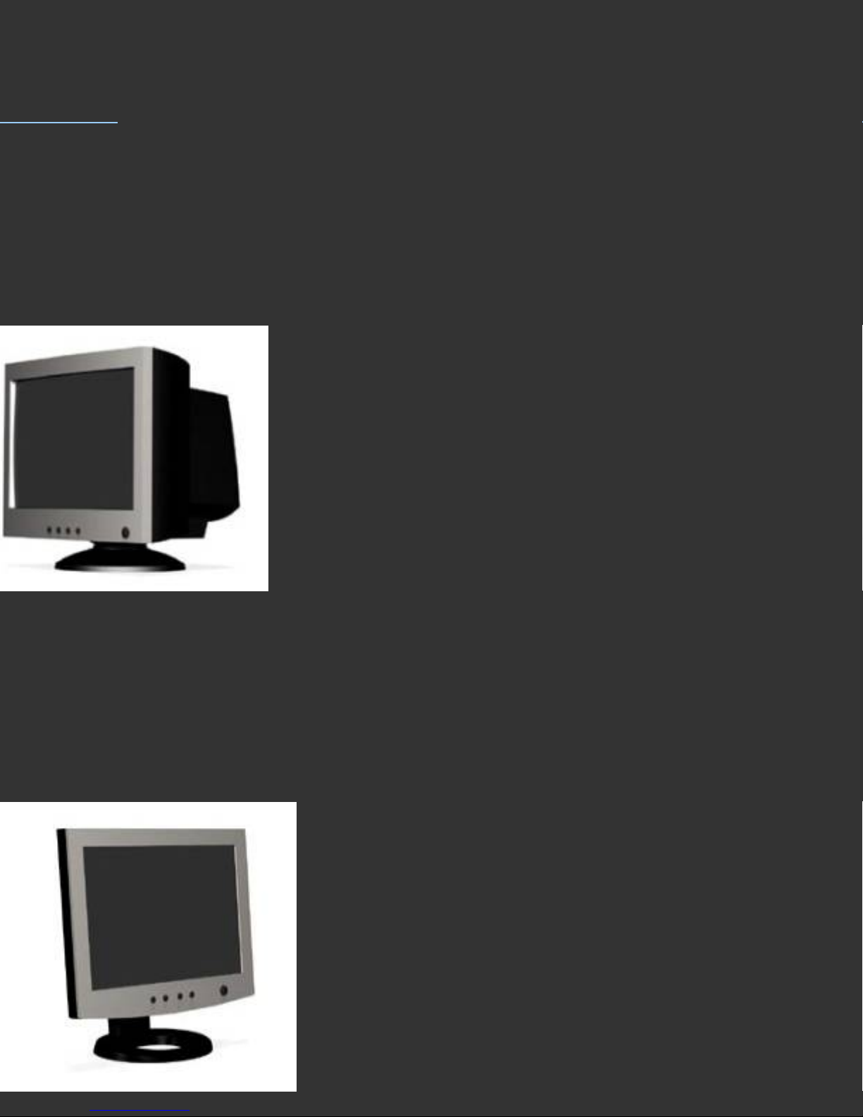
CRT Display
CRT Displays are heavy and deep. They generally resemble traditional television sets
made with glass picture tubes.
Page 21
LCD Display
LCD Displays are lighter and not so deep, often with plastic screens. They resemble
modern Thin Screen TVs.
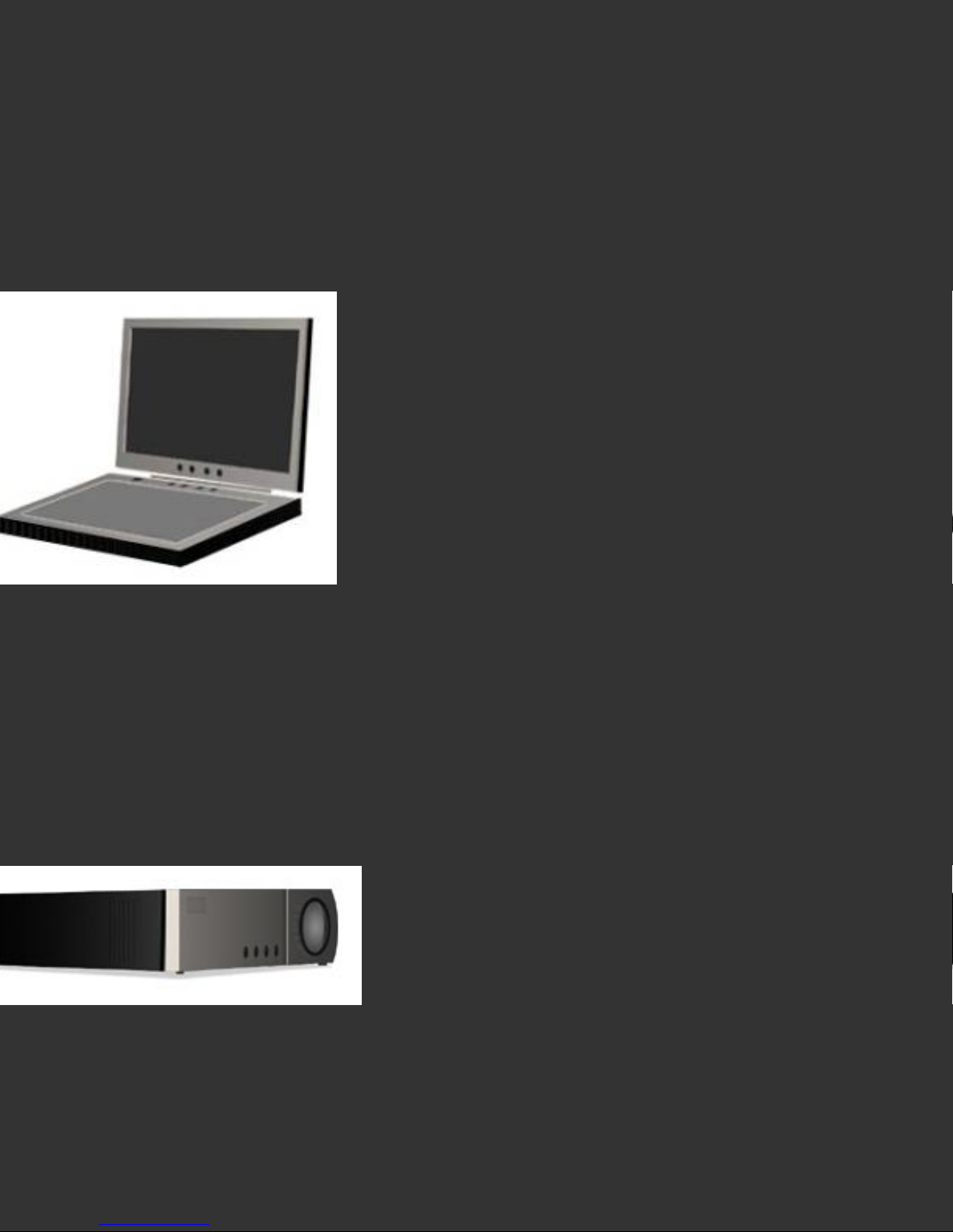
Laptop
Laptop or Notebook computers have built in processors and keyboards, as well as LCD
screens. Choose the Laptop mode to calibrate this type of display.
Projector
Front Projectors have a lens and display large images on a screen that is placed
several feet away. Some use LCD technology while others use DLP. Both are calibrated
using Projector mode.
Page 22

Further Information
For information such as a list of Frequently Asked Questions and details on all
Datacolor products be sure to visit our website: www.datacolor.com/Spyder3
Page 23

Select Target Values
Help Index
Usual Setting
Select 2.2-6500 to calibrate your display to Gamma 2.2 and White Point 6500K, the
most common choice. When calibrating projectors choose 2.2-Native.
The Purpose of This Step
This screen allows you to choose the values that you will use to calibrate your display.
The desired values are specified by selecting a Target from the popup menu. A Target
is a convenient way to collect all of the desired values together in a single setting with
a meaningful name.
The Long Answer
Target values are the desired values that you will use to calibrate your display.
Target values must include:
• White Point (the color of white on your display)
• Tone Response (often called Gamma)
The Target may optionally include:
• Black Luminance (how black your display’s blacks are)
• White Luminance (how bright your display’s whites are)
TM
• Certification (to define this as a SpyderCertified
display)
Each selection in the Target: popup is a set of these values. When you change the
menu selection, the individual values contained in the set are displayed on the right.
If there is not an existing Target that contains the values that you desire you may
create a new Target by clicking the New button. If you create a new Target, it will
remain Untitled unless you save it using the Save Target As command from the File
menu.
Page 24

A Target can specify just a Tone Response (e.g. Gamma) and a White Point or it
can also include Black and White Luminance values that are used in Measured
Luminance mode. It can also determine if the monitor will be treated as
SpyderCertified
The easiest way to create a Target is to proceed completely through a calibration
process, setting all of the Target values and then after Calibration is complete,
choose Save Target As from the File menu to create a Target that records all of the
values used for that Calibration. That Target will then be available in the Target:
popup to use for future calibrations or other monitors.
TM
.
Further Information
For information such as a list of Frequently Asked Questions and details on all
Datacolor products be sure to visit our website: www.datacolor.com/Spyder3
Page 25

Select Ambient Light Compensation
Help Index
Usual Setting
Ambient Light Compensation is an advance feature. Basic calibration does not use
Ambient Light Compensation.
The Purpose of This Step
Your visual perception of an image displayed on a monitor is influenced by the
ambient (surrounding) light in the viewing area. Perception of tone may change as the
amount of light in the room increases and decreases. The best procedure is to keep
your ambient light conditions constant and appropriate while you are doing color
critical work.
If you choose to turn Ambient Light Compensation On then the program will measure
your surrounding room light and suggest any appropriate changes to your calibration
target values and/or ambient light conditions.
The Long Answer
This analysis identifies the ambient light condition as one of five levels:
1: Very Low
2: Moderately Low
3: Medium
4: High
5: Very High
For each level, the analysis provides:
• a description
• suggested steps to take
• suggested calibration target values
Page 26

The recommended responses to respective ambient light levels 1 through 5 are as
follows:
1: Very Low: appropriate for prepress image editing. Calibrate the display to a White
Luminance level of 85-100 cd/m^2* and a White Point of 5000K (warm white) to
compensate for the eye’s cooler response at low light levels. LCD monitors (including
laptops) can be used in this situation as well as CRT displays.
2: Moderately Low: dim, but appropriate for photo image editing. Calibrate the
display to a White Luminance level of 125-150 cd/m^2 and a White Point of 5800K
(slightly warm white) to compensate for the eye’s slightly cooler response at
moderately low light levels. LCD displays (including laptops) can be used in this
situation as well as very bright CRT displays.
3: Medium: appropriate for casual photo editing. Calibrate the display to a White
Luminance level of 175-200 cd/m^2 and a White Point of 6500K (medium white) to
compensate for the eye’s moderate color response at medium light levels. Only LCD
displays (including brighter laptops) can be used at this level. An example of medium
ambient lighting would be a photographer’s customer consultation area, typically not
kept as dim as the actual color correction studio.
4: High: uncontrolled, not recommended for color critical work. Lower the ambient
light if possible, otherwise use a monitor hood and calibrate the display to the
maximum White Luminance it can produce and a White Point of 6500K or higher. An
example of High ambient lighting would be a typical office environment with overhead
fluorescent strip lights.
5: Very High: uncontrolled, not recommended for any color managed work. Requires
a very bright display. If you must work in these conditions use a monitor hood, black
umbrella or photographer’s cloak and calibrate the display to the maximum White
Luminance it can produce and a White Point of 6500K or higher. An example of Very
High ambient lighting would be previewing digital photos outdoors on a laptop display.
CRT monitors should be used only at levels 1 and 2 since most CRTs cannot achieve a
White Luminance over 125 cd/m^2. LCD monitors with limited White Luminance
Page 27

should also be used only at levels 1 and 2.
Only LCD monitors should be used at level 3 and even then, some LCD monitors and
many laptops cannot achieve the 175 cd/cm^2 needed for good viewing in those
conditions.
If your monitor cannot achieve the recommended White Luminance level for your
chosen ambient lighting, then you should lower the ambient light level to a range that
is compatible with your monitor.
Critical color work requires an environment where the ambient light is consistent and
at low to moderate levels.
For more detailed information on Ambient Lighting, Monitor Surround, and the
relationship between Luminance and White Point, see the Ambient Light Analysis
Help Page.
*cd/m^2 is a measurement of the amount of light a device emits. cd/m^2 is an
abbreviation for candelas per meter squared.
Further Information
For information such as a list of Frequently Asked Questions and details on all
Datacolor products be sure to visit our website: www.datacolor.com/Spyder3
Page 28

Ambient Light Analysis
Help Index
Surround
Luminance & WhitePoint
Usual Setting
Click on “Accept Suggested Settings”, and continue with your calibration.
The Purpose of This Step
You have set Ambient Light Compensation to “On”. On this screen, the program
presents an analysis of your surrounding lighting conditions based on the
measurement taken of those conditions. These settings are recommended for best
calibration under your current conditions. You may choose to adjust your ambient light
levels, and remeasure, to obtain more desirable results.
The Long Answer
This analysis identifies the ambient light condition as one of five levels:
Very Low
Moderately Low
Medium
High
Very High
For each level, the analysis provides:
A description
•
Suggested steps to take
•
Suggested calibration target values
•
The recommended responses to respective ambient light levels 1 through 5 are as
Page 29

follows:
Very Low: appropriate for prepress image editing. Calibrate the display to a White
Luminance level of 85-100 cd/m^2* and a White Point of 5000K (warm white) to
compensate for the eye’s cooler response at low light levels. LCD monitors (including
laptops) can be used in this situation as well as CRT displays.
Moderately Low: dim, but appropriate for photo image editing. Calibrate the display
to a White Luminance level of 125-150 cd/m^2 and a White Point of 5800K (slightly
warm white) to compensate for the eye’s slightly cooler response at moderately low
light levels. LCD monitors (including laptops) can be used in this situation as well as
very bright CRT displays.
Medium: appropriate for typical photo editing. Calibrate the display to a White
Luminance level of 175-200 cd/m^2 and a White Point of 6500K (medium white) to
compensate for the eye’s moderate color response at medium light levels. Only LCD
monitors (including laptops) can be used in this situation.
High: uncontrolled, not recommended for color critical work. Lower the ambient light
if possible, otherwise use a monitor hood and calibrate the display to the maximum
White Luminance it can produce and a White Point of 6500K or higher.
Very High: uncontrolled, not recommended for any color managed work. If you must
work in these conditions use a monitor hood, umbrella or photographer’s cloak and
calibrate the display to the maximum White Luminance it can produce and a White
Point of 6500K or higher.
CRT monitors should be used only at levels 1 and 2 since most large CRTs cannot
achieve a White Luminance over 125 cd/m^2. LCD monitors with limited White
Luminance should also be used only at levels 1 and 2.
Only LCD monitors should be used at level 3 and even then, some LCD monitors and
many laptops cannot achieve the 175 cd/cm^2 needed for good viewing in those
conditions.
If your monitor cannot achieve the recommended White Luminance level then you
Page 30

should lower the ambient light level to a range that is compatible with your monitor.
Critical color work requires an environment where the ambient light is consistent and
at low to moderate levels.
Advanced Topic: Surround
Another area worthy of attention is the monitor Surround. This is the area of the
room that your eyes see in their peripheral view while you are looking at the monitor.
The Surround should be smooth, neutral in color and dimly lit.
If the Surround is brightly colored or brightly lit this will influence your perception of
color and tone on the monitor. Viewing the same image with a different Surround
condition may result in a different perception of the image. Including exterior windows
in the Surround area causes variable influences on the eye, as well as glare and eye
fatigue, and should be avoided for any long-term or color-sensitive work. Covering the
wall behind the monitor (including any windows it may contain) with an opaque,
medium gray cloth is the best solution to situations where the wall color, brightness,
and windows, cannot be otherwise controlled.
Advanced Topic: Luminance and White Point
Each ambient light level has a recommended White Luminance that is based on
keeping monitor brightness high enough for good perception of the full display range,
and avoiding White Point adaptation by the eye to whites in the Surround, instead of
on the monitor. If the monitor is not bright enough (or conversely, the ambient light is
too bright), room lighting will reduce the eye’s acuity and ability to distinguish shadow
detail on screen. If there are bright areas in the Surround brighter than the white of
the screen, the eye may adapt to the White Point of the surround, instead of the
display, causing the display to appear both dim and off color.
Each ambient light level has a recommended White Point that is based on the eye’s
differential response to color with increasing luminance. In darker conditions, the Rods
in the eye play a larger part in vision. The blue cast the Rods incorporate into vision
mean that under low light conditions, a warmer monitor White Point is required for the
Page 31

eye to perceive color equivalently. This is why under Dim ambient conditions, with a
low monitor luminance level, a White Point of 5000K is recommended. This effect
continues up to or beyond the Medium ambient level, with increased White Point
recommendations to match.
*cd/m^2 is a measurement of the amount of light a device emits. cd/m^2 is an
abbreviation for candelas per meter squared.
Further Information
For information such as a list of Frequently Asked Questions and details on all
Datacolor products be sure to visit our website: www.datacolor.com/Spyder3
Page 32

Select Luminance Mode
Help Index
Advanced Feature
Most users will select Visual for the Luminance Mode setting. Measured is an advanced
mode – if you select Measured, you will also be asked to provide the Luminance
Values that you desire to use. The difference between these two modes is in how the
user is instructed to adjust the Luminance controls during the Calibration process.
The Purpose of This Step
When calibrating most monitors, in addition to setting the Tone Response (which
controls the Gamma) and White Point (which controls the color, not the luminance, of
white), it is also possible to adjust the Black Luminance and White Luminance levels.
This screen allows you to specify whether you want to set the Luminance levels by
eye, using visual images and incorporating information from your viewing conditions,
or by measuring with the instrument.
The Long Answer
When Visual is selected, your monitor will be calibrated to produce the most White
Luminance it can without being over-driven. The Black Luminance will be set as low as
possible to produce a good black without losing shadow detail. This is ideal for most
users who are not attempting specialized matching modes with more than one monitor
in the same viewing area.
The user is prompted to adjust each Luminance level based on observation of a visual
image. While this may seem unscientific, optimal luminance is affected by ambient
light. Since this is the case, a visual judgment by the user that takes into account
ambient light often yields a more practical result than using a predetermined number.
Measured Luminance Mode uses the instrument to measure the Black Luminance and
White Luminance levels. The measured levels are compared to the desired values and
the user is prompted to adjust the controls on the monitor to achieve the desired
Page 33

levels.
You might want to use Measured Luminance Mode if you are matching multiple
monitors that are viewed side-by-side. If you work in an environment where your
system administrator assigns specific Luminance Values, you will want to use this
mode.
If you decide that you want to select Measured Luminance Mode, you will need to
determine the appropriate Luminance Values. This is discussed in the Help for the
Specify Luminance Values screen.
Further Information
For information such as a list of Frequently Asked Questions and details on all
Datacolor products be sure to visit our website: www.datacolor.com/Spyder3
Page 34

Measured Luminance Mode
Help Index
The Long Answer
The Measured Luminance Mode feature allows you to use your Spyder to measure the
Black Luminance and White Luminance values of your display during calibration. This
can allow more consistent setting of the Luminance Values than using Visual
Luminance Mode.
Since each display is different, an initial calibration must be performed in Visual Mode
to determine the appropriate Black Luminance and White Luminance values for
your system.
If you select Measured Luminance Mode before a Visual Mode calibration has been
performed, the first time you calibrate you will be notified that a Visual Mode
calibration will be performed. Successive calibrations will then run in Measured Mode
using the appropriate values for your display.
If you select a different White Point then you will again be notified that a Visual Mode
calibration will be performed. The White Point can affect the White Luminance
value.
If you have specific Luminance Values that you want to use for calibration, you can
enter them into the Luminance fields after setting the Luminance Mode to Measured.
You might have specific Luminance Values if you are matching multiple displays. Your
system administrator may also require specific Luminance Values.
You can also create a Target File than includes the desired Black Luminance and
White Luminance values along with the White Point and Curve. A Target File is
created by selecting Save Target… in the File menu. The Target File will then
appear in the Target menu in the Select Target screen.
Further Information
Page 35

For information such as a list of Frequently Asked Questions and details on all
Datacolor products be sure to visit our website: www.datacolor.com/Spyder3
Page 36

Specify Luminance Values
Help Index
Usual Setting
Enter the Luminance Values that you want to use. Or leave the fields blank and let the
application determine them appropriately for the monitor and working environment.
The Purpose of This Step
You have set Luminance Mode to Measured. In this screen you can specify the desired
values for Black Luminance and White Luminance. These values will then be displayed
during the luminance adjustment steps and the user will be prompted to adjust the
appropriate monitor control until the measured value meets the desired value.
The Long Answer
Measured Luminance Mode uses the Spyder to measure the luminance levels. The
appropriate Display controls are then adjusted to match the desired levels. Using the
Spyder to measure the levels provides more consistent settings from one calibration to
the next.
Black Luminance Choices
Measured Luminance Mode uses Target values for Black and White Luminance.
Leaving the Black Luminance unspecified causes the software to fill this blank with the
Native Black Luminance for your display (your display’s blackness at its current
hardware settings). Native Black Luminance is often the most appropriate value for
your display, and on displays that do not offer a true Brightness control (one that
adjusts black luminance) Native Black Luminance is your only choice. If your Black
Luminance is adjustable, you may define a Target Black Luminance based on the
Multiple Display Tool, or a Studio Standard. In that case enter those values and
continue; or select the target containing these values.
White Luminance Choices
Measured Luminance Mode uses Target values for Black and White Luminance.
Leaving the White Luminance unspecified causes the software to fill this blank with the
Page 37

Native White Luminance for your display (your display’s brightness at its current
hardware settings). Native White Luminance is seldom the most appropriate value for
displays, except for laptops used in uncontrolled lighting, or projectors. You may
define a Target White Luminance based on the Multiple Display Tool, the Ambient Light
Tool, or a Studio Standard if multiple displays are being tuned to a single target. In
that case enter those values and continue; or select the target containing these
values. Otherwise leave the White Luminance box blank, and activate the Ambient
Light tool, to determine an appropriate White Luminance Level.
Advanced Topic
For accurate monitor to print comparison you will need to have a controlled lighting
environment for your print illumination. Viewing prints in general ambient room
lighting and comparing them to your monitor may be ineffective. Ideally you should
use a print viewing booth or a specialized print viewing lamp.
Both the luminance level and the color of the print viewing illumination must be
controlled.
If you are doing screen to print comparison, you may wish to adjust the White
Luminance level of the monitor so that it more closely matches the perceived
luminance of a sheet of blank printer paper as seen under your print viewing
illumination.
To do this, open a blank document window in your image processing application, place
a blank sheet of paper in your print viewing area then use your eyes to compare the
perceived luminance. Adjust the White Luminance control on the monitor to achieve a
reasonable match.
Then, launch the application, open the Colorimeter window and take a reading of
White. Note the Y value reported for xyY (you want the Capital Y value) and then recalibrate - entering in that value for the White Luminance Target.
Further Information
For information such as a list of Frequently Asked Questions and details on all
Datacolor products be sure to visit our website: www.datacolor.com/Spyder3
Page 38

Page 39

Identify Controls
Help Index
Usual Setting
Because displays are designed with many different control configurations, there is no
usual setting that can be described for this step.
The Purpose of This Step
In order for the program to provide relevant instructions in the following screens, it is
necessary for you to indicate what controls exist on your particular display device.
The Long Answer
Backlight
LCD MONITORS
This control is found on some LCD monitors.
If your LCD monitor has only one control and it is marked with the sun symbol:
(for example, most Apple LCD monitors) then it is likely that you have only a
Backlight control. Sometimes this control is marked Brightness (but there is no
corresponding Contrast control).
This control will be used to adjust the White Luminance level of the monitor. If you
have a Backlight control, you can confirm that it actually affects the monitor’s White
Luminance by observing the following image while you adjust the control across its
range from maximum to minimum:
Page 40

If the control affects White Luminance then you will see the four blocks of gray change
in intensity. You may even see the third block disappear (turn White) as you adjust
the control to its maximum setting.
Distinguishing Brightness from Backlight
If your monitor has only one control with a sun symbol, then to determine whether
this is a brightness or a backlight control, try the following test. Bring the On Screen
Menu up on your screen from the front panel controls. Adjust the control all the way to
the bright end, then scroll back all the way to the dark end. If the On Screen
Menu becomes illegibly dark along with the rest of the screen, then this is a Backlight control; if the On
Screen Menu remains visible while the rest of the screen goes dark, then this is a Brightness control.
Brightness and Contrast
LCD MONITORS AND PROJECTORS
If you have two controls, either labeled explicitly Brightness and Contrast or with the
symbols above, then you have Brightness and Contrast controls. On some displays the
Brightness control is labeled as Black Level.
The Brightness control will be used to adjust the Black Luminance level of the display
device. If you have a Brightness control, you can confirm that it actually affects the
display’s Black Luminance by observing the following image while you adjust the
control across its range from maximum to minimum:
Page 41

If the control affects Black Luminance then you will see the four blocks of gray change
in intensity. You may even see the second block disappear (turn Black) as you adjust
the control to its minimum setting.
The Contrast control will be used to adjust the White Luminance level of the display. If
you have a Contrast control, you can confirm that it actually affects the display’s
White Luminance by observing the following image while you adjust the control across
its range from maximum to minimum:
If the control affects White Luminance then you will see the four blocks of gray change
in intensity. You may even see the third block disappear (turn White) as you adjust
the control to its maximum setting.
Brightness, Contrast and Backlight
Some monitors have all three of these controls. Sometimes both the Backlight control
and the Brightness control are labeled with the sun symbol:
Because of the wide variation that occurs in the control nomenclature of displays,
please be sure to refer to the manufacturer’s user guide to correctly identify the
controls and their functions.
Further Information
For information such as a list of Frequently Asked Questions and details on all
Datacolor products be sure to visit our website: www.datacolor.com/Spyder3
Page 42

Identify Color Controls
Help Index
Usual Setting
Many displays will have Kelvin Presets. Some professional displays will also have RGB
Gain controls.
The Purpose of This Step
For the software to produce optimal results, it must be told what controls exist on your
display.
The Long Answer
Your display may have no color controls or it may have one or more of the following
types of controls. Monitor manufacturers label these in various ways: Color, RGB
Color, RGB Gain, RGB Balance, Color Temperature, ViewMatch Color, User Color,
Custom Color, Color Manager and others.
These controls are for setting the White Point in the display. Also known as Color
Temperature, this refers to the color of white. On a monitor, white is made up of Red,
Green and Blue; there are many RGB tones that can be seen as white, if they are the
lightest tone in your field of view. These are referred to as White Point, Color
Temperature or the color of white.
White Point is often specified in terms of degrees Kelvin. Common values are 5000K,
6500K and 9300K.
Kelvin Presets
If your monitor has a list of choices such as 5000K, 6500K and 9300K (and perhaps
others) then your monitor has a Color Temperature Preset control.
Page 43

Kelvin Slider
If your monitor has a slider (variable control) that allows setting any Kelvin value
(usually in a range like 4000K to 10000K) then your monitor has a Kelvin Slider
control.
RGB Sliders
If your monitor has three sliders (variable controls) that allow setting individual values
for the Red, Green and Blue channels (usually in a range of 0 to 100) then your
monitor has RGB Gain controls. Some monitors have six controls, three for white and
three for black:
Only adjust the controls for the white - usually labeled Gain or Contrast.
Do not adjust the controls for black - usually labeled Bias or Brightness; they are not
intended for adjustment with this tool.
Some displays have only two sliders (typically Red and Blue) with the third channel
fixed. You can still use the RGB slider adjustment screen to balance the whitepoint of
such displays by adjusting the variable channels.
Further Information
For information such as a list of Frequently Asked Questions and details on all
Datacolor products be sure to visit our website: http://www.datacolor.com/Spyder3
Page 44

Adjust RGB Gain
Controls
Help Index
Usual Setting
Adjust the RGB Gain controls of the monitor until the three columns in the RGB
Adjustment Graph are balanced.
The Purpose of This Step
To set the native white point of the monitor as closely as possible to your desired
Target White Point. In this way, the hardware is optimized and the software will not
need to adjust the White Point using the video card Look Up Table (LUT). This offers
optimal results.
The Long Answer
First, please realize that it is not necessary to go through the process of adjusting the
RGB Gain controls in many cases. If your Target White Point is the same as one of the
Color Temperature Presets available on the display, you can get very good results by
just using the preset. Also, it is not necessary to adjust your RGB Gains Controls every
time you calibrate your display. Usually the balance between color channels will
remain consistant for several months, though running this step allows you to check
the balance, and determine if you would like to make minor adjustments.
If you want exacting White Point control for matching side-by-side displays or
achieving the closest possible proofing matches, then this is the tool to use. However
it can be a tedious process until you become familiar with adjusting a specific display’s
on screen controls.
If you are calibrating an LCD display it is recommended that you compare the results
you obtain using a color temperature preset to the results when adjusting the RGB
controls. On some LCD displays, adjusting the RGB controls maybe unrewarding;
Page 45

using presets may be more effective. Since LCD displays vary widely between
manufacturer and model it is not possible to make a universal statement about using
RGB controls on them. It is only posible to share the observation that RGB balancing
works well on some models while on others using presets is a better choice.
Two things to understand about RGB Gains balancing:
Red, Green and Blue levels interact. For example, increasing Red can also cause Blue
and Green to decrease. Every adjustment in one color will generally cause effects on
the other two. Make small adjustments.
Adjusting the RGB levels will also affect the White Luminance. If you are using
Measured Luminance mode you also have to watch the Current White Luminance in
relation to the Target White Luminance. If you match the White Point but your White
Luminance is off, adjust ALL THREE controls up or down to affect the luminance
without affecting the White Point balance.
Your goal is to make all three columns of the RGB Graph the same height. When the
columns are level, the top of the columns will be inside the black rectangle. Be aware
that the three colors interact with each other. For example, if Green is too high then
you may either reduce Green or increase Red or Blue. This will take a little
experimentation.
If possible, start with a preset that is close to your desired target. Make only small
adjustments in the RGB levels, 2-5 percent at most. Try not to adjust the control with
the highest level - instead adjust the other two to compensate in order to optimize the
White Luminance level.
Adjust the RGB Gain controls of the monitor as indicated by the levels on the bar
graph in the RGB Gains screen. For example, if the bar graph shows that Red is too
low, this means that you should increase the Red Gain (or decrease Green and Blue)
using the monitor controls. The levels graph is relative; adjusting the bars up and
down will only change their height in relation to the target rectangle, not the overall
graph.
RGB Gains Fields Definitions:
Page 46

Color Target – the value that you specified earlier as the desired white color (White
Point) to calibrate the monitor to (in CIE xy)
Current – the current measured white color (in CIE xy)
Difference – the difference between the Target and the Current color values expressed
in Delta ab. A difference of zero means that the monitor is adjusted to exactly the
desired white color. The monitor setting is close enough if the difference is less than
0.5
Kelvin Target – the value that you specified earlier as the desired white color (White
Point) to calibrate the monitor to (in degrees Kelvin)
Current – the current measured white color (in degrees Kelvin)
Luminance Target – if Measured Luminance Mode has been specified then this will
show the desired White Luminance value that was entered for the calibration
Current – the current measured White Luminance in candelas per meter squared
Further Information
For information such as a list of Frequently Asked Questions and details on all
Datacolor products be sure to visit our website: http://www.datacolor.com/Spyder3
Page 47

Adjust Kelvin Slider
Help Index
Usual Setting
Adjust to the value that matches the desired Target White Point.
The Purpose of This Step
To set the display hardware as closely as possible to the desired White Point.
The Long Answer
Your monitor has a slider (continuously variable control) for selecting White Point. This
means that the monitor controls give you a way to select the White Point value from a
continuous range.
Set the slider value so that it matches the White Point target value that you are
calibrating to (for example, if your target is 6500K then set the slider to 6500K.)
For users with a single display, an exact White Point is not critical; any value that the
eye sees as white, and that relates to a white sheet of paper under your print viewing
lighting, will work reasonably well. Using a White Point of 6500K has the advantage of
matching the White Point of the most common RGB working spaces (e.g. AdobeRGB,
sRGB) so that non-color managed applications will offer the closest match for these
files.
Using a specific White Point chosen to match your usual media under your viewing
lights (such as gloss photo paper under a desktop proofing light) may offer a closer
match for that specific combination.
Further Information
For information such as a list of Frequently Asked Questions and details on all
Datacolor products be sure to visit our website:
http://www.datacolor.com/Spyder3
Page 48

Page 49

Adjust Kelvin Presets
Help Index
Usual Setting
Choose the value that matches the desired Target White Point. If an exact match is
not available then choose the next higher setting.
The Purpose of This Step
To set the display hardware as closely as possible to the desired White Point.
The Long Answer
Your display has presets for selecting White Point. This means that the display controls
give you a way to select the White Point value from a list of choices.
Usually this means that you have a choice of three or four settings that are expressed
in degrees Kelvin. Common choices are 5000K, 6500K and 9300K.
Select the setting that matches the White Point target value that you are calibrating
to. If an exact match is not available then choose the next higher value (for example,
if your target is 6500K and your available presets are 5000K and 6550K, choose
6550K.)
For users with a single display, an exact White Point is not critical; any value that the
eye sees as white, and that relates to a white sheet of paper under your print viewing
lighting, will work reasonably well. Using a White Point of 6500K has the advantage of
matching the White Point of the most common RGB working spaces (e.g. AdobeRGB,
sRGB) so that non-color managed applications will offer the closest match for these
files.
Using a specific White Point chosen to match your usual media under your viewing
lights (such as gloss photo paper under a desktop proofing light) may offer a closer
Page 50

match for that specific combination.
Further Information
For information such as a list of Frequently Asked Questions and details on all
Datacolor products be sure to visit our website:
http://www.datacolor.com/Spyder3
Page 51

Set Brightness and Contrast to Factory Default
Help Index
Usual Setting
For
the simplest, and often best, calibration, set the Brightness and Contrast controls of the display device to
their Factory Default settings. If there are no default settings available, 50% contrast, and 100% brightness
are typical starting points.
The Purpose of This Step
LCD MONITORS
Brightness and Contrast controls on LCD displays do not work the same as those
controls do on CRT displays. Testing of various displays has shown that adjusting
these controls away from their Factory Default values may affect the display in
undesirable ways.
Adjusting these controls on LCD displays can lead to reduction in dynamic range and
distortion of the Tonal Response Curve.
PROJECTORS
Brightness and Contrast controls are not of much use on projectors, where brightness
is affected by distance from the screen, and black is effected by ambient light levels.
Adjusting these controls away from their Factory Default values can lead to reduction
in dynamic range and other
harmful effects.
The Long Answer
It is important to reset these controls to their Factory Default values. Even if you
intend to experiment with adjusting these controls to other settings, please begin by
resetting them to defaults, as this is the best starting point.
Page 52

The controls for your display device should include a Reset or Recall command that
can be invoked to perform this function. Most displays have this function in the onscreen controls. Some displays use a combination of buttons held down at power-on to
invoke the reset. It is advisable to refer to the User Guide for your monitor or check
with the manufacturer’s Technical Support. If there are no default settings available,
50% contrast, and 100% brightness are typical starting points.
It is recommended to confirm the operation of the Reset command by setting the
Brightness and Contrast controls to some known value (like 33 and 77) that is not an
end condition like 0 or 100. Invoke the Reset command and check that the Brightness
and Contrast values have been changed to something else. Default values are often
end conditions like 0 or 100 - sometimes midpoint conditions like 50.
In the following screens instructions for adjusting the Brightness and Contrast controls
are provided. Such adjustments could be necessary in the unlikely case of a display
that does not have a Factory Default setting. These facilities are also given to allow for
those users who wish to experiment with tweaking these controls. However the basic
recommendation is not to adjust the Brightness and Contrast controls of an LCD
monitor or projector away from their Factory Default values.
Further Information
For information such as a list of Frequently Asked Questions and details on all
Datacolor products be sure to visit our website: www.datacolor.com/Spyder3
Page 53

Set Black Luminance
Help Index
Usual Setting
It is simplest, and often most effective, to leave the Brightness control of the monitor
or projector set to the Factory Default value. Most LCD displays do not have an actual
Brightness control; for these monitors this step is skipped.
The Purpose of This Step
This step checks that the Black Level is set low enough that the display shows its
maximum black without being so low that loss of shadow detail results.
The Long Answer
PROJECTORS
For users with projectors we recommend that you leave the Brightness control set at
its Factory Default value.
This recommendation is given regardless of the type of technology used in
the projector: LCD, DLP, etc.
LCD DISPLAYS
For LCD displays, because of the large variation in controls and behaviors that they
exhibit, it is not possible to provide one single set of instructions that work for all
displays except the following:
For users with LCD displays we recommend that you leave the Brightness
control set at its Factory Default value.
Brightness and Contrast controls on LCD displays do not work the same as those
controls do on CRT displays. Even if you do have a Brightness control on your LCD and
Page 54

it is a reasonable digital approximation of how that control works on a CRT it is
possible that adjusting it will not affect the display of the Black/Dark Gray patches
shown here. You may find that one of the following situations occur:
* Even when you turn the control to its Minimum setting you still see all four blocks.
* Even when you turn the control to its Maximum setting you still can’t see any
difference between the blocks.
For this reason, and others based on our testing of LCD monitors, we recommend that
you leave the Brightness control set to the Factory Default setting.
If you do elect to adjust the Brightness control of an LCD monitor be sure that you
don’t confuse it with the Backlight control. Backlight controls and Brightness controls
are sometimes labeled with the same type of ‘sun’ symbol:
On an LCD display Black Luminance is sometimes controlled by the Brightness
control. The Brightness control is often identified with the sun symbol:
The Brightness control is sometimes labeled Black Level.
Set this control to the lowest setting that still allows you to see four separate blocks in
the Black Luminance visual guide:
You should be able to see four separate blocks inside the gray surround. If you do not
see four blocks, increase the Brightness control until you can just distinguish between
the leftmost (pure black) block and the adjacent (darkest gray) block. If adjusting the
Brightness control does not change the visibility of the four black blocks, then reset to
default value, and move to the next step of the calibration process.
Page 55

The goal in Brightness adjustment is to find the lowest setting that allows you to see
all four blocks.
If the level is set too low there won’t be any difference between Black and Dark Gray
and you will not be able to distinguish variations in the dark shadows of images:
If the level is set too high then Black will appear gray and your display will display
reduced dynamic range with weak contrast.
Note: Effect Of Ambient Light
Please keep in mind that ambient lighting (the background lighting in your room)
affects your ability to perceive blacks. In bright office lighting it may be impossible to
distinguish all four blocks on many displays. For serious color work it is recommended
that you work in very subdued lighting for CRT displays, and subdued lighting for LCD
displays. Loosening half or more of the bulbs in office fluorescent fixtures, and closing
blinds on nearby windows is usually necessary to create appropriate display viewing
conditions in offices. In instances where this is impossible or undesirable, using LCD
displays offers better viewing balance than the dimmer display of CRT screens.
Further Information
For information such as a list of Frequently Asked Questions and details on all
Datacolor products be sure to visit our website: www.datacolor.com/Spyder3
Page 56

Set LCD White Luminance
Help Index
Usual Setting
On LCD displays White Luminance may be adjusted by the Backlight control. The
Backlight control is often identified with a “sun” symbol. To begin, set this control to
its maximum value.
The Purpose of This Step
This step assures that the display is producing sufficient light so that it can be easily
viewed; but is not being overdriven, which could result in loss of highlight detail.
The Long Answer
If your display has a function to reset the Backlight control to its Factory Default value
then you should use that. This will probably set the control to maximum. If there is no
Factory Reset set the control to the maximum value. To adjust the display’s luminance
to the ambient lighting, choose the Ambient Light Compensation option.
Also observe the White Luminance visual guide:
You should be able to see four separate blocks inside the gray surround.
If you do not see four blocks:
Page 57

Reduce the Backlight control until you can just distinguish between the rightmost
(pure white) block and the adjacent (lightest gray) block.
White Luminance is sometimes referred to as Brightness, but that name can cause
confusion with the Brightness control, which actually adjusts Black Luminance.
Note: Backlight and Brightness May Have Same Symbol
Some LCD displays have both a Backlight control and a Brightness control labeled
with the same ‘sun’ symbol. Be careful to adjust the Backlight control, not the
Brightness control.
If your LCD display has only one control and it is marked with the “sun” symbol: (for
example, most Apple LCD monitors) then it is likely that you have only a Backlight
control. Sometimes this control is incorrectly labeled Brightness; but there is no
corresponding Contrast control. Treat such a control as a Backlight control.
If you have two controls, either labeled explicitly Brightness and Contrast or with the
‘sun’ and ‘half moon’ symbols: then you have Brightness and Contrast controls. This
typically means that you do not have a Backlight control.
Because of the variation that occurs in the control names for LCD displays, please
refer to the manufacturer’s user guide to correctly identify the controls and their
functions.
Note: Effect Of Ambient Light
Please keep in mind that ambient lighting (the background lighting in your room)
effects your ability to perceive whites. In bright office lighting it may be impossible to
distinguish all four blocks on many displays. For serious color work it is recommended
Page 58

that you work in very subdued lighting for CRT displays, and subdued lighting for LCD
displays. Loosening half or more of the bulbs in office fluorescent fixtures, and closing
blinds on nearby windows is usually necessary to create optimal monitor viewing
conditions in offices. In instances where this is impossible or undesirable, using LCD
displays offers better viewing balance than the dimmer display of CRT screens.
Further Information
For information such as a list of Frequently Asked Questions and details on all
Datacolor products be sure to visit our website:
www.datacolor.com/Spyder3
Page 59

Check Calibration
Help Index
Usual Setting
If you are running the application for a normal periodic calibration, mark the radio
button to check the current calibration. This will typically take less time than running a
full calibration and may show that re-calibration is not needed at this time.
The Purpose of This Step
This gives the user the ability to check the accuracy of the currently applied calibration
to see whether it is still within a reasonable range of the target values. If the monitor
has drifted too far (or if its controls have been adjusted) then re-calibration will be
recommended.
The Long Answer
Conventionally, monitor calibration products simply alert the user to re-calibrate the
display after a period of time has passed. Whether or not re-calibration is actually
necessary at that time can be determined by taking a few measurements (fewer than
re-calibration takes). If the current calibration is still valid then there is no need to
recalibrate.
Over time the user could modify their re-calibration reminder time based on the
results of Check Calibration.
Further Information
For information such as a list of Frequently Asked Questions and details on all
Datacolor products be sure to visit our website: www.datacolor.com/Spyder3
Page 60

Current Calibration
Help Index
Usual Setting
Setting will depend on the results just measured as part of Check Calibration.
The Purpose of This Step
This is the analysis of the measurements taken for Check Calibration. By comparing
the Current values to the Target values a decision can be made as to whether recalibration is necessary.
The Long Answer
Periodically, displays need to be re-calibrated because their underlying hardware
characteristics such as White Luminance will decay over time. As this decay occurs,
the calibration needs to be updated to keep the display performance constant.
Current Calibration displays the current (just measured) values of important
characteristics for the display which are controlled by calibration.
The application will compare the Current values to the Target values and make a
determination as to whether re-calibration is needed at this time. The program will set
the default value of the radio buttons based on this decision.
Further Information
For information such as a list of Frequently Asked Questions and details on all
Datacolor products be sure to visit our website: www.datacolor.com/Spyder3
Page 61

Select Gray Balanced Calibration
Help Index
Usual Setting
The usual choice for this option is ‘on’.
The Purpose of This Step
This option allows the user to disable the gray balance algorithm used in calibration.
When calibrating certain displays, disabling gray balance may provide improved
results.
The Long Answer
By default, this option is always turned on for all displays.
For LCD displays this is usually the best choice in all cases.
CRT displays generally do not need additional gray balancing during calibration
therefore some users turn off this option for their CRTs to accelerate the calibration
process.
Our current experience with projectors shows mixed results. In many cases LCD
based projection devices work better with gray-balance turned on and DLP based
projectors work better with it off, but this may not be universal.
Further Information
For information such as a list of Frequently Asked Questions and details on all
Datacolor products be sure to visit our website: www.datacolor.com/Spyder3
Page 62

Select Gray Balance Refinement
Help Index
Usual Setting
Most users will leave this setting at the default value which is ‘off’.
The Purpose of This Step
Allows the user to indicate whether they want the calibration process to spend
additional time to see if the gray balance of the calibration can be improved.
The Long Answer
The normal calibration process is to measure the display, calculate the correction
curve and load that into the video card.
If Gray Balance Refinement is on then an additional step is performed following the
normal process. After the correction curve is loaded into the video card, the
application will then take readings to see how close the calibrated display is to the
desired target value. At points in the gray ramp the program will adjust the calibration
slightly and then measure the display again to see if the result is closer or farther from
the target.
This process will take several minutes as the application steps through the gray ramp
tweaking and re-measureing the calibration results.
The end result of this process may be better gray balance. Any improvement may be
at the expense of tonal response accuracy and/or gradient smoothness.
Further Information
For information such as a list of Frequently Asked Questions and details on all
Datacolor products be sure to visit our website: www.datacolor.com/Spyder3
Page 63

Select White Luminance Reduction
Help Index
Usual Setting
This setting will be ‘off’ except for special circumstances. Turn this setting ‘on’ if you
experience a color cast when calibrating a display that does not have a White
Luminance control or whose White Luminance control is already at its minimum setting.
The Purpose of This Step
This setting provides an option that may allow users of some displays
to achieve a more acceptable calibration.
The Long Answer
Some displays may be set to produce very high White Luminance output. This setting
may be so high that it causes clipping of the RGB channels which can result in a color
cast.
Normal calibration depends on the user being able to adjust the White Luminance of
the display using controls on the display itself. Some displays have no such control or
their control may not have sufficient range to reach an appropriate setting.
White Luminance can also be adjusted in software by the calibration. Normally this is
not done because it can result in reduced dynamic range. Turning this setting ‘on’
allows the calibration process to adjust White Luminance in software for the benefit of
color cast reduction with the possible trade-off of reduced dynamic range.
Further Information
For information such as a list of Frequently Asked Questions and details on all
Datacolor products be sure to visit our website: www.datacolor.com/Spyder3
Page 64

Remove Sensor
Help Index
Usual Setting
Remove the Spyder from the screen.
The Purpose of This Step
We are done taking readings, and the Spyder should now be removed from the screen.
The Long Answer
The Spyder is no longer needed on screen, and can be returned to its stand. Leaving it
on screen will interfere with reading further instructions.
Further Information
For information such as a list of Frequently Asked Questions and details on all
Datacolor products be sure to visit our website:
www.datacolor.com/Spyder3
Page 65

Profile Name
Help Index
Usual Setting
Accept the default name.
The Purpose of This Step
This step defines the name of your monitor’s ICC profile. Supplying a custom name for
your profile can make it easier to find.
The Long Answer
The name should include information about what device it is for. This is the name that
will appear in the system and within applications that use the display profile.
For example:
Windows – Control Panels-> Display Properties-> Advanced-> Color Management
Macintosh – System Preferences-> Displays-> Color
If you use the same name for the profile every time you calibrate then the new profile
will overwrite the previous profile. This will prevent a buildup of outdated device
profiles from previous calibrations and is recommended practice. Using a unique name
each time will allow you to save outdated display profiles, for comparison. The History
function eliminates most need for saving outdated display profiles.
Additional Profiles For Projectors
If you are calibrating a projection device there will be an additional option available
titled create additional profiles for higher ambient light levels. If you mark this
checkbox then two additional profiles will be created along with the normal profile.
These profiles may be helpful if the ambient light in the projection area is higher than
it was when you performed the calibration.
Page 66

These additional profiles will have the same name as the normal profile with “+1” and
“+2” appended to the name.
If you set a different device profile in the system you may need to re-launch any
currently running color managed applications for them to notice the change.
Photoshop, on Mac and Windows, will generally recognize profile changes on the fly
but other programs may not.
Further Information
For information such as a list of Frequently Asked Questions and details on all
Datacolor products be sure to visit our website:
www.datacolor.com/Spyder3
Page 67

SpyderUtility
Help Index
Spyder Utility Features
Usual Setting
Spyder Utility will run at all times; DO NOT remove or shutdown the Utility, or you
may adversely effect your color.
The Purpose of This Step
Spyder Utility needs to monitor your system to assure that the correct display profiles
and calibrations are in use. If you choose Real-Time Ambient Light Monitoring, then
the Utility will continuously check your lighting conditions as well.
The Long Answer
Spyder Utility is installed as a Startup Item on your computer. It has a number of
functions. These include:
Assuring that your display profiles and their matching calibration data has been
loaded at startup for each calibrated display.
Checking at frequent intervals that the correct profiles and calibration data are
still in use.
TM
Checking that the more stringent standards of Spyder Certification
are in effect
on any displays where Certification has been chosen.
Continuously monitoring Ambient Light levels if the Real-Time Ambient Light
feature has been activated.
Further Information
Page 68

For information such as a list of Frequently Asked Questions and details on all
Datacolor products be sure to visit our website:
http://www.datacolor.com/Spyder3
Page 69

SpyderProof
TM
Help Index
Test Image Descriptions
Usual Setting
SpyderProof will typically be used for a quick check of the results from building a
profile with your Spyder3 products. For more advanced analysis, see ‘The Long
Answer’ below.
The Purpose of This Step
To allow users to review the results of their new profile, before moving on to using it.
The Long Answer
SpyderProof is a software interface and feature set intended to replace the “Before
and After” and “Print Preview” screens in previous Datacolor products. It consists of a
matrix of 16 carefully selected images covering a wide range of subjects and lighting
conditions, and controls to manipulate how these images are viewed.
IMAGE WINDOW
Page 70

The image window shows a matrix of all 16 available images, grouped in four
quadrants. Quadrant One (upper left) contains saturated colors. Quadrant Two (upper
right) covers skintones. Quadrant Three (lower left) contains landscapes and
gradients. Quadrant Four (lower right) covers grayscale (black and white) images.
Clicking on any quadrant will bring that group of four images up to fill the window.
Clicking on an individual image in the quadrant view will further zoom to fill the
window with that single image. Clicking on the individual image will return to the
overview image. The ‘Enlarge Image’ button will open whichever image or group of
images is currently being viewed in a resizable floating window for a more detailed
view.
SPECIAL TIP: Using the Control key while clicking on the Image Window will replace
the Test Images with a 729 patch ordered color gradient for checking the full color
range of your profile.
CONTROLS
SpyderProof Controls in display calibration software contain two sections: a Display
Page 71

Profile section and a Print Emulation section. Both sections are for on-screen display
(not printing) only. Spyder3Print Controls offer both on-screen and print capabilities,
so that users can print any or all of the test images directly from Spyder3Print to
check profile results.
Display: Noneditiable text box will display name of monitor profile just built (S3) or OS
defined monitor profile (PFP). Both are actually the same, since just built profile has
already been set of OS monitor profile. Checkbox will allow user to toggle Video
Corrections on and off (flash and null VLUTs). Text box is not a popdown list to avoid
applying profiles for other monitors, or profiles for same monitor but with different
hardware adjustments, neither of which would be valid.
Print: Popdown list will default to printer profile just created (Spyder3Print) or short
list of typical device types to emulate (Spyder3Pro/Elite), such as photolabs and
typical inkjet inks and papers. Checkbox will allow user to toggle Print Proof on and
off. Changing profiles in popdown will proof to other printer profiles, but using same
monitor profile.
Device Emulation: Popdown will start with a short list of typical device types to
emulate, such as presses and photolabs, plus generic inkjet profiles. User built profiles
can be selected as well.
TEST IMAGE DESCRIPTIONS
Saturated Colors Quadrant:
This section is intended to show saturated colors, for use in checking how your display
or printer deals with very intense colors, both synthetic and photographic.
Page 72

Image One: Colors (q1i1).jpg. This image includes synthetic step gradients of
Magenta, Blue, Cyan, Red, Yellow, Green, and Black. The high saturation patches in
many of these gradients will be outside the gamut of most monitors, as well as most
printer/ink/paper combinations. They are useful to check your system against
intentionally out of gamut colors.
The photographic section of the image includes highly saturated photographic colors.
These are not as intense as synthetic colors, but can still be challenging to many
devices. Typical desktop monitors will fail to reach many of the reds, oranges, yellows,
and light greens in this image. Even AdobeRGB gamut monitors can’t reach some of
the most saturated yellows and light greens. Prints on glossy/luster media will reach
all but the most saturated reds in this image, but matte/art papers will also be unable
to accurately portray many of the dark green areas.
Image Two: Pottery (q1i2).jpg. This image offers an excellent range of unusual
saturated colors, lime greens, oranges, purples, golden yellows. Also excellent french
grays, black rims, and specular highlights. On screen this demonstrates monitor high
saturation channel blends. In print it tests high saturation ink blends with unusual
colors. A few of the most saturated deep yellows are out of gamut even on an
AdobeRGB monitor, with standard desktop LCDs a few of the most saturated orange
tones will also be out of device gamut. In Print this image is entirely in gamut with
many inkjet printers on glossy/luster papers, but has saturated dark tones that are
out of the range of matte/art papers, resulting in somewhat less saturated dark areas
in print than on screen.
Page 73

Image Three: NightShot(q1i3).jpg. This image exhibits the effects of colors too
bright for the camera’s dynamic range: many of the neon signs burn to white in the
image, but their less intense reflections on the water show the true colors of the signs.
Use this image to check saturated colors against a dark background, and to view
shadow noise or grain in the dark areas.
Image Four: Fabrics(q1i4).jpg. Extremely saturated, glossy colors folded to exhibit
ocular highlight band, and gradiate to shadows below. Textile detail can be used to
test for posterization and detail capabilites on screen and in print. This image was shot
in full sun at high altitude which further enhances color detail and saturation. On
screen this demonstrates monitor high saturation channels and blends. In print it tests
high saturation inks and blends in many colors. This image emphasizes detail, not
smoothness of gradients.
Skin Tones Quadrant:
Image One: PortraitColor(q2i1).jpg. This portrait shot offers a very yellow
skintone under very yellow lighting, so users can see what the yellow end of the
skintone range looks like on their device. Fine detail in fly-away hairs against a dark
colored background can be used to check for over-inking in prints, as dark mixed
colors create the highest ink loading, and fine light elements against them show over-
Page 74

inking by bleeding and eliminating the narrow light areas. Fabric detail in the jacket
can be used to check shadow detail capabilityt on screen and in print. Out of focus
flowers in the lower background can be used to check print gradiation from colors to
black, for breaks in gradient.
Image Two: GirlWithOrchids(q2i2)jpg. Pure, pink skintones with much cooler
skylighting, to test the red end of the skintone range. Denim blue running into deep
shadow offers a challenge for printer drivers in producing dark blues with texture
detail. The Orchids display a wide range of near white tones, and can be used to check
for highlight detail on screen and in print. Fabric detail in both the pink and blue
fabrics will show ability of device to produce differing tones in these colors.
Image Three: Cuba(q2i3).jpg. Another excellent check of highlight details in the
musicians sidelit white shirt, showing cool window lighting, and warm reflected
lighting. Shadow detail and shadow saturation check in face and shadowed mural.
Deep skintones into shadow test device’s ability to display color tones evenly into
darkness.
Page 75

Image Four: Reflections (q2i4).jpg. Tungsten highlights in hair burn to device (or
paper) white, clearly showing ramp of warm yellow tones to device white,
demonstrating the change that can occur when a color ramp ends in a mismatched
white. Mix of warm and cool highlights in maniquin and window reflections. Warm and
cool highlights in mirrorballs. Hot pink highlights in light gel. A challenging image to
print on many papers due to mixed lighting and multilayered transparency.
Landscape and Gradients Quadrant:
Image One: Stone Vase (q3i1).jpg. Exceptional range of greens from a yellowish
grass green to deep evergreen, with green shadow tones, and dark shadow detail,
plus stone vase neutrals gradiating from near highlights to shadow tones, with fine
detail throughout, to show posterization effects. Garden bench in the deep shadows in
the background provides exceptional shadow detail test. Difficult light purples in Hosta
blossoms. On screen this demonstrates monitor green gamut and hue, plus green
channel range to black. In print it tests Yellow/Cyan blended greens or ink carts
greens depending on device.
Page 76

Image Two: Adobe Church (q3i2)jpg. Pure, saturated sky gradient. Sunlit adobe
surfaces with detail and gradiation. Deep shadow detail in tower windows and on rear
ell. High contrast greenery in forground. Excellent sharp contrasts between sky and
crosses, rail and adobe, adobe and sky etc.
Image Three: Sunrise (q3i3)jpg . Unusually pure sky gradient from pink to purple
and white in sky. Subtle mountain blue gradient right to left. Unusual shadow detail in
ochre tones in forground which are particularly challenging to print without losing
saturation.
Image Four: Landscape (q3i4)jpg. Excellent pastel colors in full pallette: reds,
oranges, yellows, greens, blues, plus purple shadow details. Tells a great deal about
monitor whitepoint and hightlight tonality, shows light color blending in printer inks.
Black and White and Test Image Quadrant:
Page 77

Image One: B&Wportrait(q4i1).jpg. Detailed grayscale skin and hair textures and
gradients. This image tests neutrality and detail, with a focus on the skintone range.
Includes both sharply focussed, and out of focus elements, producing a range of detail
textures.
Image Two: Infinity(q4i2).jpg. This image focusses on the dark tones, and the
edges between light elements and darker backgrounds, as well as wood grain detail
and other darktone patterns. This image is a good test for gamma (how light or dark
the midtone on a device appear).
Image Three: ScooterB&W(q4i3).jpg. Very smooth gradients in a wide range of
tones. Highlight detail in white paint and upholstery, deep shadows in handgrip
texture. Selective focus produces smooth gradients in edge areas. The well distributed
range of grays, detail in all zones, and gradients combine to produce an image that
allows for easy visual determination of neutrality.
Page 78

Image Four: B&WTestImage(q4i4).jpg. Datacolor’s standard B&W Test Image
includes a wide array of pictoral and graphic elements. Use the long gray ramp at the
top and short radial grayscale at the bottom to judge smoothness and continuity. Use
the stepped gray ramp for checking distinct values. Review the enlarged details above
each image for highlights and shadows: The Trees in Fog detail checks fine distinction
in neutrals, while the Boat Planks Reflection checks the ability to distinguish deep
shadow details.
Further Information
For information such as a list of Frequently Asked Questions and details on all
Datacolor products be sure to visit our website:
http://www.datacolor.com/Spyder3
Page 79

Expert Console
Help Index
Expert Console Features
Usual Setting
The Display Calibration Assistant is recommended for most users as the easiest way to
use Spyder3Elite. Only advanced users should use the Expert Console.
The Purpose of This Step
To provide advanced users with a single screen covering all elements of display
targeting, calibration, and profiling
The Long Answer
Spyder3Elite’s Expert Console is provides as an advanced user feature. It allows the
user to see and control most elements of display targeting, calibration, and profiling
from a single convenient screen. Settings selected in the Console will trigger the same
lists, options, and processes that would occur in the Assistant-based workflow. The
New Display Assistant and StudioMatch
Expert Console, to define characteristics of displays, and to determine multiple display
targets automatically.
TM
Assistant should be run in advance of the
Expert Console Features
The overview below gives basic descriptions of the functions in the Expert Console.
More detailed information on them can be found on the Help pages covering each
function in the Assistant workflow. Please refer to the Help Index to locate the correct
pages for each function.
Select Display to Calibrate
This popup list allows you to select which display the Console affects. Changing this
selection will move the Console window to the selected display.
Page 80

Target
This section includes popups listing predefined, and user defined targets, and for
seperately defining White Point and Gamma. The Gamma/Non-Gamma radio
buttons change the Gamma popup list from one type to the other. The Save as
Target button allows saving any configuration as a new custom target.
Target Luminance Values
This section allows users to choose between Visual Mode, where black and white
luminance values are set for the user, and Measured Mode, where these values can
be defined numerically in the Black Luminance and White Luminance entry boxes,
and matched by display measurements. Settings in this section will be saved as part
of Saved Targets in the Target section above.
Options
Other functions are grouped together in this section. These include Apply Video
Calibration, which allows users to see a real-time ‘before and after’ view of their
displays with and without calibration corrections applied. This Display to be
Certified allows users to tag a display for Certification. Check Ambient Light Level
when Calibrating determines whether the Ambient Light Assistant will be run as part
of future calibrations; this is not necessary once an appropriate Ambient Light level
has been established. Real Time Monitoring detemines whether Ambient Light will
be monitored continuously while the computer is in operation. Current Ambient
Light Level… lists the currently defined Ambient Light Level, and the Measrure
button below it allows a new Ambient Light Reading to be taken.
Calibration and Profiling
This section allows the user to chose specific Calibration and Profiling functions.
Selecting Calibrate only, will create calibration corrections, and build a profile in
which these corrections will be stored; this is identical to the Assistant based
calibration process. Chosing Profile only will profile the current state of the display
without calibration. This is a specialty function, not recommended for standard uses.
Checking both Calibrate and Profile will produce a result similar to the standard
Calibrate process, with the exception of defining the Calibration as 256 discrete points,
instead of defining it as a single number gamma curve (when possible) in the standard
process. The Measure button here will trigger whichever Calibration/Profiling
functions have been checked. The Check Calibration button will measure a set of
Page 81

color patches to determine if the display required recalibration at this time.
Further Information
For information such as a list of Frequently Asked Questions and details on all
Datacolor products be sure to visit our website:
http://www.datacolor.com/Spyder3
Page 82

Select Spyder Certification
Help Index
Usual Setting
The default value of this setting is ‘Off’. Enabling this setting depends on the users’
needs for display calibration status. This setting does not affect the actual calibration
process in any manner.
The Purpose of This Step
The user can choose to have the calibration status of the display monitored
continuously and to be notified if the display falls out of certification.
The Long Answer
Spyder Certification is a process carried out by the Spyder Utility which runs in the
background on your computer. Spyder Certified indicates that the conditions of a
particular display are within the parameters defined for certification.
Certfication status is indicated on the display by a small icon in the menu bar (on
Macintosh) or a small icon in the System Tray (on Windows). If the display is out of
certification the user can select an item from the Spyder Utility menu for an
explanation of what conditions have been violated and how to return the display to
certified state.
Specifically, the parameters which define Certification are:
The profile assigned to the display by the operating system is a Datacolor
•
Spyder3-created profile
• That profile was created with Spyder Certification set to ‘on’
The LookUp Table (LUT) currently loaded in the video card is the LUT from
•
that profile
Ambient light conditions are the same as when the display was calibrated
•
The display has been recalibrated within the time limit specified in the
•
Spyder Utility’s preferences
The display has been run through full calibration within the time limit
•
Page 83

specified in the Spyder Utility’s preferences
•
The computer has been turned on for at least the time specified in the
Spyder Utility’s preferences
Further Information
For information such as a list of Frequently Asked Questions and details on all
Datacolor products be sure to visit our website: www.datacolor.com/Spyder3
Page 84

StudioMatch
TM
Help Index
Usual Setting
This depends on whether you are:
•
Matching displays that are all connected to one computer
Matching displays that are connected to multiple computers
•
The Purpose of This Step
There are two scenarios that StudioMatch™ works with. The user will indicate which
scenario to run through depending on their situation.
The Long Answer
Is it just this one computer whose displays you want to have match, or are there
many different computers whose displays you want to have match each other?
Just this computer:
This means that there is only one computer and that computer has more than one
display attached to it. The computer has a multi-head video card and/or multiple video
cards. If you are running the Windows operating system, see below for issues
regarding multi-head cards.
In this process, the application will take measurements of each attached display and
then mediate their capabilities with the desired target settings selected by the user,
and also the ambient lighting conditions.
Then all displays will be run through the calibration process to adjust them to
matching settings.
This computer and other computers:
This means that more than one computer is involved. Each computer has one or more
displays attached to it. Performing the matching process involves gathering
information from all of the computers onto one machine. The application running on
that machine will then examine the capabilities of all displays and mediate their
capabilities with the desired target settings selected by the user and also the ambient
lighting conditions.
Page 85

Information will then be distributed out to all of the computers indicating the target
settings that they should use. Then the calibration process will be run on every
computer to adjust their displays to matching settings.
Note: Multiple Monitors
Computers using the Windows operating system with multiple displays may need to
have a separate video card for each display. Multi-head video cards (a single card that
drives two or more displays) that are not PCI Express cards often are not capable of
holding unique calibrations for multiple displays. Each display must have its own
profile, created specifically for that display, associated with it. Associating different
profiles to displays attached using a multi-head video card may not function correctly
under Windows.
Computers using the Macintosh operating system do not have this issue. There is no
problem using multi-head video cards on Macintosh.
Further Information
For information such as a list of Frequently Asked Questions and details on all
Datacolor products be sure to visit our website: www.datacolor.com/Spyder3
Page 86

In Closing
Help Index
The Long Answer
The goal of calibration and profiling is to maintain a consistent color environment. To
achieve consistency, calibration should be performed on a regular schedule. In
general, calibrating every two weeks is reasonable. You may set a calibration reminder
in the Preferences.
Calibration Interval
How often should you calibrate:
Daily - fanatical
Weekly - demanding
Bi-Weekly - reasonable
Monthly - OK
Yearly - not acceptable
We hope to see you again in a couple of weeks…
Further Information
For information such as a list of Frequently Asked Questions and details on all
Datacolor products be sure to visit our website:
www.datacolor.com/Spyder3
Page 87

Curves Window
Help Index
The Long Answer
The Curves Window provides a graphical display of the tonal response characteristics
of the monitor system. This includes representations of the monitor’s default behavior,
the desired behavior and the actual behavior.
The x-axis of the graph represents all of the possible input values that can be sent to
the monitor in the range of 0-255 for Red, Green and Blue values.
The y-axis of the graph represents the actual measured output value of the monitor
corresponding to each input level. This axis is shown with 255 levels corresponding to
the range of actual measured output luminance values from minimum to maximum.
Channel
This menu allows you to choose to view plots for all channels simultaneously or to
view plots for just the Red, Green or Blue channels individually.
Curves
Target
When this checkbox is marked, a plot is shown of the desired (target) tonal response
that has been specified by the user. For example, if the user specifies a Target of
Gamma 1.8 then the plot that is shown for the Target Curve here in the Curves
Window will be for an ideal mathematical response curve of Gamma 1.8.
The target curves for the Red, Green and Blue channels are identical and therefore
draw right on top of each other. In Global mode you will only see a blue line because
that is the last channel drawn. The line will change to Red or Green if you choose to
view individual channels in the Channel menu.
Uncalibrated
Page 88

When this checkbox is marked, a plot is shown of the default tonal response character
of the monitor. That is, the tonal characteristics of the monitor in its uncalibrated state
before any adjustment has been performed. You will usually see, to some degree,
three lines for this plot because the Red, Green and Blue channels of the uncalibrated
monitor do not have the same tonal response characteristics.
Calibrated
When this checkbox is marked, a plot is shown of the tonal response character of the
monitor after it has been calibrated by the application. This plot should very closely
follow the plot of the Target curve. This is an indication of how well the calibration
actually adjusted the monitor’s behavior from the uncalibrated state to match the
desired (target) state. You may want to toggle the Target curve display off and on to
compare it with the Calibrated curve.
Correction
When this checkbox is marked, a plot is shown of the actual correction curves that are
downloaded to the lookup table (LUT) in the video card. This lookup table is calculated
to adjust the tonal response of the monitor from the uncalibrated behavior to the
desired (target) behavior.
The Correction curves are plotted using the actual values for input and output in the
range of 0-255.
Linear vs non-linear
If monitors were linear devices then the graph of their tonal response would be a
diagonal line from 0,0 to 255,255. However, monitors do not behave in a linear
fashion. Generally their tonal response character follows a power curve represented by
the Gamma function (typically in the range of Gamma 2.2.)
For example, if the response were linear, then an input value of 128 would result in an
output value of 128. With a monitor that has a response of Gamma 2.2 an input value
2.2
of 128 results in an output value of (128/255)
= 56.
Page 89

The plot of the tonal response of the monitor is generated as follows: Color samples
are displayed on the monitor that step from black to white. For each sample displayed
the output luminance of the monitor is measured with the colorimeter instrument. The
resulting table of input RGB -vs- output Luminance values is then plotted.
Further Information
For information such as a list of Frequently Asked Questions and details on all
Datacolor products be sure to visit our website: www.datacolor.com/Spyder3
Page 90

Information Window
Help Index
The Long Answer
The Information Window provides numerical feedback on the process and quality of
the calibration performed.
Luminance
These values show the output luminance values, in candelas per meter squared,
measured on the monitor when full Black and full White sample colors are displayed.
Uncalibrated
The values measured when the monitor is in its uncalibrated state. That is, the
luminance values displayed by the monitor before any adjustment has been performed.
Target
The desired or target values specified by the user. These values can be set in the
Specify Luminance Values screen when Measured Luminance Mode has been
selected.
These values will be displayed to guide the user when they are setting the Black and
White Luminance levels during a Measured Luminance Mode calibration.
The Target values are only displayed and used when Luminance Mode has been set
to Measured.
Calibrated
The values measured when the monitor is in its calibrated state. That is, the
luminance values displayed by the monitor after being adjusted.
Page 91

In Visual Luminance mode this is simply an informative item that indicates how
much the calibration process affected the output luminance of the monitor. In
particular, if the White Point was adjusted during calibration you will see a drop in
White Luminance from Uncalibrated to Calibrated which is the trade-off for getting
the correct white point.
In Measured Luminance mode this shows how close the user adjusted the
luminance levels using the monitor controls during calibration.
White Point
These values show the chromaticity values, in CIE xy, measured on the monitor when
a full White sample is displayed.
Uncalibrated
The value measured when the monitor is in its uncalibrated state. That is, the
chromaticity value of the white point before any adjustment has been performed.
Target
The desired or target value specified by the user. This value can be set in the Select
Target screen or the Select White Point screen.
Calibrated
The value measured when the monitor is in its calibrated state. That is, the
chromaticity value of the white point after being adjusted. This value should closely
match the Target value and is an indication of how well the calibration actually
adjusted the monitor’s behavior from the uncalibrated state to match the desired or
target state. The Delta E White Point value is another indication of this.
If the user specified that the monitor has RGB Gain controls then the value of the
calibrated white point shows how close the user adjusted the white point using the
monitor controls during calibration.
Page 92

Phosphors
These values show the chromaticity values, in CIE xy, measured on the monitor when
full Red, Green and Blue samples are displayed. The values are stored, after chromatic
adaptation, in the ICC profile for the monitor. Applications will use these values as the
basis for their transformations of colors to be displayed on the monitor.
Delta E
White Point
This is a measure of how close the calibrated White Point is to the desired or target
White Point value. In Measured Luminance mode this is calculated as the
difference in Luv color space between the Target and Calibrated values for White
Point and White Luminance. In Visual Luminance mode this is not really Delta E
but Delta uv because it is calculated only as the difference in uv chromaticity (because
there is no numeric luminance target in Visual Luminance mode).
A Delta E of less than 3 is good. Less than 2 is quite good. Less than 1 is excellent but
not often achieved in practice (if you get Delta E less than 1, consider taking a trip to
Las Vegas).
50% Gray
This is simply an informative item that provides an indication of how well the
calibrated monitor is tracking gray chromaticity. This is an indication of the gray
tracking of the monitor hardware. The value is calculated as the difference in uv
chromaticity between a reading of 128 gray and the Target White Point. As such it is
not really Delta E but actually Delta uv (there being no luminance target for gray).
Determining Target Luminance Values
When setting the desired calibration values, the user can specify that Luminance
Mode is either Visual or Measured. The difference between these two modes is in
how the user is instructed to set the Black and White Luminance levels during the
Calibration process.
For most users, Visual mode is recommended. If you want to use Measured mode
then read on because you must first determine the Target Luminance Values.
Page 93

On CRT monitors, the Brightness control adjusts the Black Luminance level of the
monitor. The Contrast control adjusts the White Luminance level.
On some LCD monitors this is also true but it is difficult to determine. LCD monitors
may also have a third control called Backlight that is different than the Brightness or
Contrast control. Some LCD monitors have only a Backlight control that is usually
confusingly labeled with the same icon that is used for the Brightness control (a sun).
Our general experience with LCD monitors that have Brightness and Contrast controls
is that the monitor performs best if those controls are set to their Factory Default
values. You may experiment with the adjustment of these controls but this is not
recommended and it is up to you to determine whether or not you get better results.
When calibrating in Visual mode, the user is prompted to turn the Contrast control to
maximum, which means that the monitor will work at its highest White Luminance
value. The user is prompted to adjust the Brightness control based on observation of a
visual target that should result in an appropriate Black Luminance level. While this
may seem unscientific, optimal black luminance is affected by ambient light. Since this
is the case, a visual judgment by the end user that takes into account ambient light
often yields a better result than if a number was to be handed down through the ages
by a color god.
If Black Luminance is too low then dark tones will display as black and there will be a
loss of shadow detail. If Black Luminance is too high then black will appear as a dark
gray instead of a pure black and shadow detail will appear washed out or lacking in
contrast.
The purpose of Measured mode is that once appropriate Target Luminance Values
have been determined you can accurately reproduce these levels from one calibration
to the next by measuring the Black and White Luminance of the monitor using the
colorimeter instrument.
So the real question is how to determine Target Luminance Values. That is the title of
this section after all. It may be that your System Administrator or similar source has
already provided you with Luminance Targets. If not then what you want to do is
Page 94

determine the correct Black and White Luminance levels for your working environment
by performing a Visual mode calibration and then use those levels in the future when
you run in Measured mode. Thus you establish target values visually and then
consistently set to those values in all future calibrations numerically.
Remember, the main purpose of Calibration is consistency. You choose your target
values and then you maintain your monitor at those values through regular calibration.
Gamma
These values show the calculated gamma of a gray ramp measured on the monitor.
This is generally an approximation since most monitors do not exhibit a tone response
that exactly follows the shape of gamma. Each calculated value is followed by a
number in parenthesis which provides an indication of how closely the measured curve
actually matches the gamma curve being indicated.
Uncalibrated
The value measured when the monitor is in its uncalibrated state. That is, the gamma
of the display before any adjustment has been performed.
Target
The desired or target value specified by the user. This value can be set in the Select
Target screen or the Select Gamma screen.
Calibrated
The value measured when the monitor is in its calibrated state. That is, the tone
response of the display after being adjusted expressed as a gamma value. This value
should closely match the Target value and is an indication of how well the calibration
actually adjusted the monitor’s behavior from the uncalibrated state to match the
desired or target state.
Further Information
For information such as a list of Frequently Asked Questions and details on all
Datacolor products be sure to visit our website: www.datacolor.com/Spyder3
Page 95

Page 96

Preferences
Help Index
Usual Setting
Preferences will usually be left at their default settings.
The Purpose of This Step
Preferences allow users to choose program options and select the measurement
instrument to use.
The Long Answer
The following items may be adjusted in Preferences:
Sensor
Select <none> or Spyder3. When troubleshooting sensor USB connection a good
practice is:
•
Select <none>
Unplug the Spyder
•
Plug the Spyder back in
•
Select Spyder3
•
When the sensor is found, the SN and Version fields in “Sensor Information” will be
filled in.
Port
There is no need to make any selection to this menu. When Spyder3 is selected this
menu will change to “USB”.
Recalibration Warning
You can indicate whether you want the Spyder Utility to remind you to re-calibrate the
display after a period of time. You can also disable the reminder by selecting “Never”.
Show Spyder3 status in menu bar
This controls whether or not the Spyder Utility will display a menu for easy access. On
Macintosh this will appear on the right side of the menu bar. On Windows this will
Page 97

appear in the System Tray.
Check for software updates
The application will check to see if there is a newer version available and if so inform
the user. If you do not want the program to do this then unmark the checkbox.
Further Information
For information such as a list of Frequently Asked Questions and details on all
Datacolor products be sure to visit our website: www.datacolor.com/Spyder3
Page 98

Advanced Preferences
Help Index
Usual Setting
Advanced Preferences will usually be left at their default settings.
The Purpose of This Step
Advanced Preferences allow advanced users to choose special options for specific
purposes.
The Long Answer
The following items may be adjusted in Advanced Preferences:
User Interface
If you wish to present a simpler user interface to your users you can select different
levels here.
Basic – No options are presented, just runs Calibrate and Profile
Classic – Some options: Gamma, White Point. Some adjustments: Black and White
Luminance.
Advanced – All options including arbitrary response curves. All adjustments including
RGB Gains.
Delta E Warning Level
This specifies the Delta E level which will trigger the Exceeded Delta E warning dialog.
The default value is 3.
The warning dialog will be displayed after Profiling or Validation if the measured White
Point differs from the Target White Point by a Delta E that exceeds this value. (Please
see below for an explanation of Delta E.)
Page 99

Show RGB Sliders as an option in the Identify Color Controls screen
By default, this option is always turned off because most users do not need to adjust
the RGB Sliders of the display.
Users who really want to adjust the RGB Gain Controls on a display can turn this
option on. When this option is enabled, the user will be able to indicate to the program
that their display has RGB Gain controls. The application will then include a step
during calibration which assists the user in adjusting those controls.
Adjust White Luminance in software for displays that do not have a White
Luminance control
Some displays do not include a control for adjusting their White Luminance level. In
general, the White Luminance Control is a Backlight control on LCD monitors and a
Contrast control on CRT monitors.
If this option is turned on, the application will, if necessary, adjust (lower) the White
Luminance of the display being calibrated as part of the Look Up Table (LUT) that is
downloaded to the video card.
This can, however, result in some loss of dynamic range for the display. It is always
best to adjust White Luminance using a control on the display if possible.
Explanation of Delta E
White Point
This is a measure of how close the calibrated White Point is to the desired or target
White Point value. In Precision mode this is calculated as the difference in Lab color
space between the Target and Calibrated values for White Point and White
Luminance. In Visual Luminance mode this is not really Delta E but Delta ab
because it is calculated only as the difference in ab chromaticity (because there is no
numeric luminance target in Visual Luminance mode).
A Delta E of less than 3 is good. Less than 2 is quite good. Less than 1 is excellent but
not often achieved in practice.
Further Information
For information such as a list of Frequently Asked Questions and details on all
Datacolor products be sure to visit our website: www.datacolor.com/Spyder3
Page 100

 Loading...