

Page 1

Operating Manual
Original operating manual
Datacolor CONDITIONER™
Sample conditioning cabinet
with display controller MB2
9020-0129, 9120-0129 without lights
9020-0190, 9120-0190 with lights
Issue 06/2017 Art. No. 7001-0346
Page 2

Content
1. SAFETY .................................................................................................................. 6
1.1 Legal considerations ........................................................................................................................... 6
1.2 Structure of the safety instructions ...................................................................................................... 6
1.2.1 Signal word panel ...................................................................................................................... 6
1.2.2 Safety alert symbol .................................................................................................................... 7
1.2.3 Pictograms ................................................................................................................................. 7
1.2.4 Word message panel structure ................................................................................................. 8
1.3 Localization / position of safety labels on the cabinet ......................................................................... 8
1.4 Type plate ........................................................................................................................................... 9
1.5 General safety instructions on installing and operating the cabinets ............................................... 10
1.6 Intended use ..................................................................................................................................... 12
1.7 Operating instructions ....................................................................................................................... 12
1.8 Measures to prevent accidents ......................................................................................................... 13
1.9 Resistance of the humidity sensor against harmful substances ....................................................... 14
2. CABINET DESCRIPTION ..................................................................................... 15
2.1 Cabinet overview ............................................................................................................................... 16
2.2 Instrument panel ............................................................................................................................... 17
2.3 Lateral control panel ......................................................................................................................... 17
2.4 Rear view with water connections .................................................................................................... 18
3. COMPLETENESS OF DELIVERY, TRANSPORTATION, STORAGE, AND
INSTALLATION .................................................................................................... 19
3.1 Unpacking, and checking equipment and completeness of delivery ................................................ 19
3.2 Guidelines for safe lifting and transportation .................................................................................... 19
3.3 Storage .............................................................................................................................................. 20
3.4 Location of installation and ambient conditions ................................................................................ 21
4. INSTALLATION AND CONNECTIONS................................................................ 22
4.1 Spacer for wall distance .................................................................................................................... 22
4.2 Wastewater connection ..................................................................................................................... 23
4.3 Freshwater supply ............................................................................................................................. 23
4.3.1 Automatic fresh water supply via water pipe ........................................................................... 24
4.3.2 Manual fresh water supply via external freshwater can (option) ............................................. 26
4.4 Optional water treatment system BINDER Pure Aqua Service ........................................................ 26
4.5 Optional external freshwater and wastewater cans .......................................................................... 26
4.5.1 Mounting the freshwater can ................................................................................................... 27
4.5.2 Mounting the wastewater can.................................................................................................. 28
4.5.3 Mounting with wastewater recycling ........................................................................................ 29
4.6 Placement of the light cassettes (cabinet with lights) ....................................................................... 30
4.7 Electrical connection ......................................................................................................................... 30
4.8 Connection of the optional voltage changer ..................................................................................... 31
5. FUNCTIONAL OVERVIEW OF THE MB2 CHAMBER CONTROLLER ............... 33
5.1 Operating functions in normal display ............................................................................................... 35
5.2 Display views: Normal display, program display, chart-recorder display ......................................... 36
5.3 Controller icons overview .................................................................................................................. 37
5.4 Operating modes ............................................................................................................................... 39
5.5 Controller menu structure ................................................................................................................. 40
5.5.1 Main menu ............................................................................................................................... 41
5.5.2 “Settings” submenu ................................................................................................................. 42
5.5.3 “Service” submenu .................................................................................................................. 42
5.6 Principle of controller entries ............................................................................................................. 43
5.7 Performance during and after power failures .................................................................................... 43
5.8 Performance when opening the door ................................................................................................ 44
Datacolor CONDITIONER™ (MB2) 06/2017 page 2/126
Page 3

6. START UP ............................................................................................................ 44
6.1 Turning on the cabinet ...................................................................................................................... 44
6.2 Controller settings upon start up ....................................................................................................... 44
6.3 Turning on/off humidity control .......................................................................................................... 45
7. SET-POINT ENTRY IN “FIXED VALUE” OPERATING MODE ........................... 46
7.1 Set-point entry for temperature, humidity, light intensity, and fan speed through the “Setpoints”
menu ................................................................................................................................................. 47
7.2 Direct setpoint entry for temperature, humidity, and light int ensity via Normal display .................... 48
7.3 Special controller functions via operation lines ................................................................................. 48
8. TIMER PROGRAM: STOPWATCH FUNCTION .................................................. 49
8.1 Starting a timer program ................................................................................................................... 49
8.1.1 Performance during program delay time ................................................................................. 49
8.2 Stopping a running timer program .................................................................................................... 50
8.2.1 Pausing a running timer program ............................................................................................ 50
8.2.2 Cancelling a running timer program ........................................................................................ 50
8.3 Performance after the end of the program ........................................................................................ 50
9. TIME PROGRAMS ............................................................................................... 51
9.1 Starting an existing time program ..................................................................................................... 51
9.1.1 Performance during program delay time ................................................................................. 52
9.2 Stopping a running time program ...................................................................................................... 52
9.2.1 Pausing a running time program ............................................................................................. 52
9.2.2 Cancelling a running time program ......................................................................................... 52
9.3 Performance after the end of the program ........................................................................................ 52
9.4 Creating a new time program ............................................................................................................ 53
9.5 Program editor: program management ............................................................................................. 53
9.5.1 Deleting a time program .......................................................................................................... 54
9.6 Section editor: section management ................................................................................................ 55
9.6.1 Add a new program section ..................................................................................................... 56
9.6.2 Copy and insert or replace a program section ........................................................................ 56
9.6.3 Deleting a program section ..................................................................................................... 57
9.7 Value entry for a program section ..................................................................................................... 58
9.7.1 Section duration....................................................................................................................... 58
9.7.2 Set-point ramp and set-point step ........................................................................................... 59
9.7.3 Special controller functions via operation lines ....................................................................... 60
9.7.4 Setpoint entry .......................................................................................................................... 61
9.7.5 Tolerance range ...................................................................................................................... 61
9.7.6 Repeating one or several sections within a time program ...................................................... 62
9.7.7 Saving the time program ......................................................................................................... 63
10. WEEK PROGRAMS ............................................................................................. 64
10.1 Starting an existing week program.................................................................................................... 64
10.2 Cancelling a running week program ................................................................................................. 64
10.3 Creating a new week program .......................................................................................................... 65
10.4 Program editor: program management ............................................................................................. 66
10.4.1 Deleting a week program ........................................................................................................ 67
10.5 Section editor: Section management ................................................................................................ 68
10.5.1 Add a new program section ..................................................................................................... 69
10.5.2 Copy and insert or replace a program section ........................................................................ 69
10.5.3 Deleting a program section ..................................................................................................... 70
10.6 Value entry for a program section ..................................................................................................... 70
10.6.1 Set-point ramp and set-point step modes ............................................................................... 70
10.6.2 Weekday .................................................................................................................................. 71
10.6.3 Start time ................................................................................................................................. 71
10.6.4 Setpoint entry .......................................................................................................................... 72
10.6.5 Special controller functions via operation lines ....................................................................... 72
Datacolor CONDITIONER™ (MB2) 06/2017 page 3/126
Page 4

11. NOTIFICATION AND ALARM FUNCTIONS ........................................................ 73
11.1 Notification and alarm messages overview ...................................................................................... 73
11.1.1 Notifications ............................................................................................................................. 73
11.1.2 Alarm messages ...................................................................................................................... 74
11.1.3 Messages concerning the humidity system ............................................................................ 74
11.2 State of alarm .................................................................................................................................... 75
11.3 Resetting an alarm, list of active alarms ........................................................................................... 75
11.4 Tolerance range settings .................................................................................................................. 76
11.5 Activating / deactivating the audible alarm (alarm buzzer) ............................................................... 77
12. TEMPERATURE SAFETY DEVICES ................................................................... 77
12.1 Over temperature protective device (class 1) ................................................................................... 77
12.2 Overtemperature safety controller class 3.1 ..................................................................................... 77
12.2.1 Safety controller modes ........................................................................................................... 78
12.2.2 Setting the safety controller ..................................................................................................... 78
12.2.3 Message and measures in the state of alarm ......................................................................... 79
12.2.4 Function check ........................................................................................................................ 79
13. USER MANAGEMENT ......................................................................................... 80
13.1 Authorization levels and password protection .................................................................................. 80
13.2 Log in................................................................................................................................................. 83
13.3 Log out .............................................................................................................................................. 84
13.4 User change ...................................................................................................................................... 84
13.5 Password assignment and password change .................................................................................. 85
13.5.1 Password change .................................................................................................................... 85
13.5.2 Deleting the password for an individual authorization level .................................................... 87
13.5.3 New password assignment for “service” or “admin” authorization level when the password
function was deactivated ........................................................................................................ 88
13.6 Activation code .................................................................................................................................. 89
14. GENERAL CONTROLLER SETTINGS ................................................................ 90
14.1 Selecting the controller’s menu language ......................................................................................... 90
14.2 Selecting the temperature unit .......................................................................................................... 90
14.3 Setting date and time ........................................................................................................................ 91
14.4 Display configuration ......................................................................................................................... 92
14.4.1 Adapting the display parameters ............................................................................................. 92
14.4.2 Touchscreen calibration .......................................................................................................... 93
14.5 Network and communication ............................................................................................................. 94
14.5.1 Ethernet ................................................................................................................................... 94
14.5.2 Web server .............................................................................................................................. 95
14.5.3 E-Mail ...................................................................................................................................... 96
14.6 USB menu ......................................................................................................................................... 97
15. GENERAL INFORMATION .................................................................................. 98
15.1 Service contact page ........................................................................................................................ 98
15.2 Current operating parameters ........................................................................................................... 98
15.3 Event list ............................................................................................................................................ 99
15.4 Counter of operating hours (cabinet with lights) ............................................................................. 100
15.5 Technical information on the cabinet .............................................................................................. 100
16. CHART RECORDER DISPLAY ......................................................................... 101
16.1 Views ............................................................................................................................................... 101
16.1.1 Show and hide legend ........................................................................................................... 101
16.1.2 Switch between legend pages .............................................................................................. 101
16.1.3 Show and hide specific indications ....................................................................................... 102
16.1.4 History display ....................................................................................................................... 102
16.2 Setting the parameters .................................................................................................................... 105
Datacolor CONDITIONER™ (MB2) 06/2017 page 4/126
Page 5

17. HUMIDIFICATION / DEHUMIDIFICATIO N SYSTEM ......................................... 106
17.1 Function of the humidifying and dehumidifying system .................................................................. 108
18. DEFROSTING AT REFRIGERATING OPERATION (CABINET WITHOUT
LIGHTS) ............................................................................................................. 109
19. ILLUMINATION SYSTEM (CABINET WITH LIGHTS) ....................................... 110
20. MAINTENANCE, CLEANING, AND SERVICE .................................................. 111
20.1 Maintenance intervals, service ........................................................................................................ 111
20.2 Replacement of the fluorescent tubes ............................................................................................ 112
20.3 Cleaning and decontamination ....................................................................................................... 112
20.3.1 Cleaning ................................................................................................................................ 113
20.3.2 Decontamination ................................................................................................................... 115
21. DISPOSAL.......................................................................................................... 116
21.1 Disposal of the transport packing ................................................................................................... 116
21.2 Decommissioning ............................................................................................................................ 116
21.3 Disposal of the cabinet in the member states of the EU ................................................................. 116
21.4 Disposal of the cabinet in non-member states of the EU ............................................................... 117
22. TROUBLESHOOTING ....................................................................................... 118
23. TECHNICAL DESCRIPTION .............................................................................. 120
23.1 Factory calibration and adjustment ................................................................................................. 120
23.2 Over current protection ................................................................................................................... 120
23.3 Definition of usable volume ............................................................................................................. 120
23.4 Technical Data ................................................................................................................................ 121
23.5 Equipment ....................................................................................................................................... 122
23.6 Spare parts (extract) ....................................................................................................................... 123
23.7 Dimensions size 115 ....................................................................................................................... 124
24. EU DECLARATION OF CONFORMITY ............................................................. 125
All efforts have been made to ensure the accuracy of the information presented in this format. However,
should any errors be detected, Datacolor appreciates your efforts to notify us of these oversights.
Changes are periodically made to this information and are incorporated into forthcoming versions. Datacolor reserves the right to make improvements and/or changes in the product(s) and/or program(s) described in this material at any time.
©2010 Datacolor. Datacolor, and other Datacolor product trademarks are the property of Datacolor.
Datacolor CONDITIONER™ (MB2) 06/2017 page 5/126
Page 6
Dear customer,
For the correct operation of the Datacolor CONDITIONER™ sample conditioning cabinet, it is important
that you read this operating manual completely and carefully and observe all instructions as indicated.
Failure to read, understand and follow the instructions may result in personal injury. It can also lead to
damage to the cabinet and/or poor equipment performance.
1. Safety
This operating manual is part of the components of delivery. Always keep it handy for reference. The
device should only be operated by laboratory personnel especially trained for this purpose and familiar
with all precautionary measures required for working in a laboratory. Observe the national regulations on
minimum age of laboratory personnel. To avoid injuries and damage observe the safety instructions of
the operating manual.
WARNING
Failure to observe the safety instructions.
Serious injuries and cabinet damage.
Observe the safety instructions in this operating manual.
Carefully read the complete operating instructions of the cabinets.
1.1 Legal considerations
This operating manual is for informational purposes only. It contains information for installing, start-up,
operation and maintenance of the product. Note: the contents and the product described are subject to
change without notice.
Understanding and observing the instructions in this operating manual are prerequisites for hazard-free
use and safety during operation and maintenance. In no event shall Datacolor be held liable for any damages, direct or incidental arising out of or related to the use of this manual.
This operating manual cannot cover all conceivable applications. If you would like additional information,
or if special problems arise that are not sufficiently addressed in this manual, please ask your dealer or
contact us directly by phone at the number located on page one of this manual
Furthermore, we emphasize that the contents of this operating manual are not part of an earlier or existing agreement, description, or legal relationship, nor do they modify such a relationship. All obligations on
the part of Datacolor derive from the respective purchase contract, which also contains the entire and
exclusively valid statement of warranty administration. The statements in this manual neit her augm ent nor
restrict the contractual warranty provisions.
1.2 Structure of the safety instructions
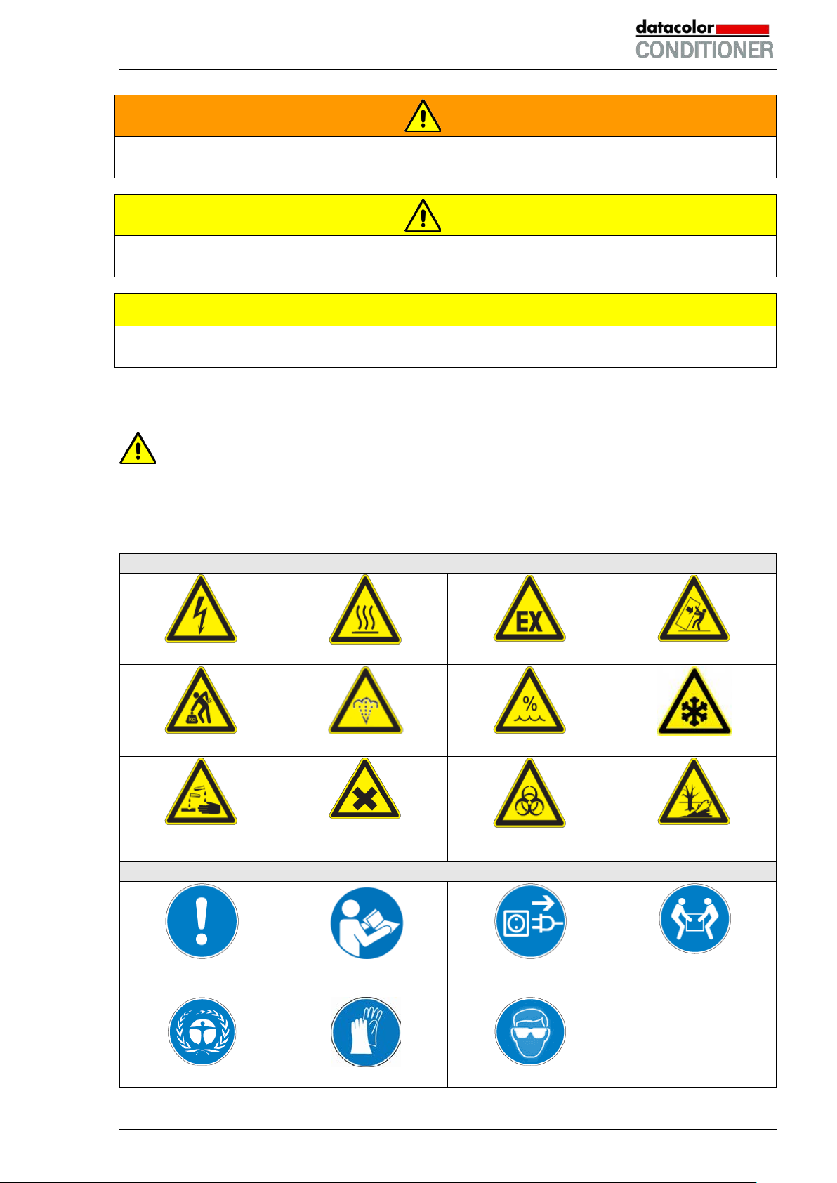
In this operating manual, the following safety definitions and symbols indicate dangerous situations following the harmonization of ISO 3864-2 and ANSI Z535.6.
1.2.1 Signal word panel
Depending on the probability of serious consequences, potential dangers are identified with a signal
word, the corresponding safety color, and if appropriate, the safety alert symbol.
DANGER
Indicates an imminently hazardous situation that, if not avoided, will result i n death or serious (irreversible) injury.
Datacolor CONDITIONER™ (MB2) 06/2017 page 6/126
Page 7
Warning signs
Hot surface
Danger of frost
or chemical burns
Mandatory action signs
instructions
plug
Wear protective gloves
WARNING
Indicates a potentially hazardous situation which, if not avoided, could result in death or serious (irreversible) injury.
CAUTION
Indicates a potentially hazardous situation which, if not avoided, may result in m oderat e or m inor (reversible) injury.
CAUTION
Indicates a potentially hazardous situation which, if not avoided, may result in dam age to the product
and/or its functions or of a property in its proximity.
1.2.2 Safety alert symbol
Use of the safety alert symbol indicates a risk of injury.
Observe all measures that are marked with the safety alert symbol in order to avoid death or
injury.
1.2.3 Pictograms
Electrical hazard
Lifting hazard
Risk of corrosion and /
Scalding hazard
Harmful substances
Explosive atmosphere
High humidity
Biohazard
Stability hazard
Pollution Hazard
Mandatory regulation
Environment protection
Datacolor CONDITIONER™ (MB2) 06/2017 page 7/126
Read operating
Disconnect the power
Wear safety goggles
Lift with several persons
Page 8
Prohibition signs
water
Pictograms (warning signs)
Do NOT touch
Do NOT spray with
Information to be observed in order to ensure optimum function of the product.
Do NOT climb
1.2.4 Word message panel structure
Type / cause of hazard.
Possible consequences.
∅ Instruction how to avoid the hazard: prohibition
Instruction how to avoid the hazard: mandatory action.
Observe all other notes and information not necessarily emphasized in the same way, in order to avoid
disruptions that could result in direct or indirect injury or property damage.
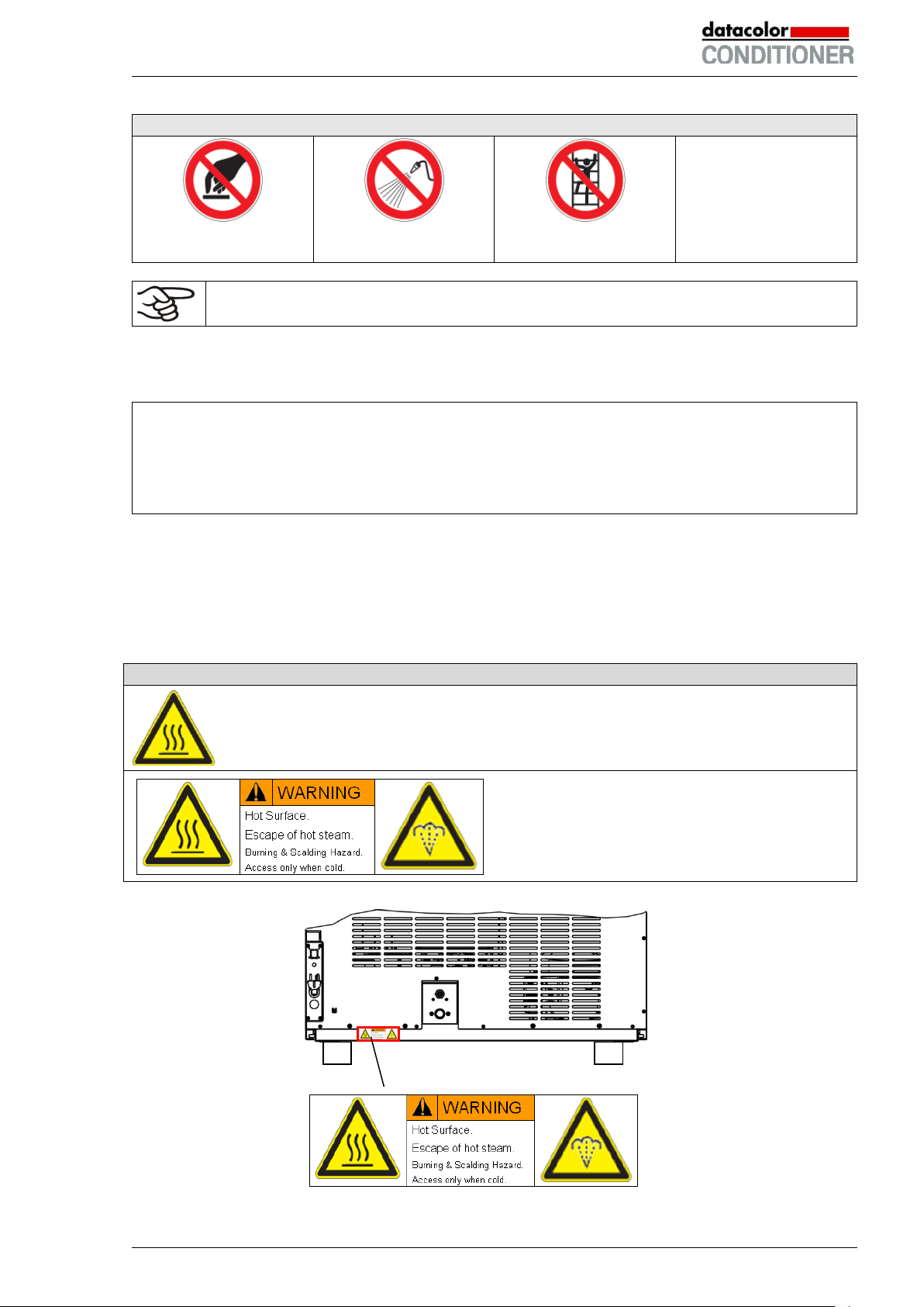
1.3 Localization / position of safety labels on the cabinet
The following labels are located on the cabinet:
Hot surface (inner glass door above the glass door handle)
Burning and scalding hazard (cabinet rear)
Datacolor CONDITIONER™ (MB2) 06/2017 page 8/126
Figure 1: Position of labels on the cabinet rear
Page 9
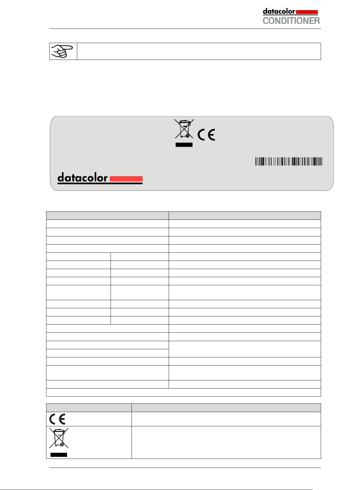
Indications of the type plate (example)
Information
datacolor
Distributor: Datacolor
BINDER GmbH
Manufacturer: BINDER GmbH
Datacolor CONDITIONER™
Model designation
Sample conditioning cabinet
Device name
Built
2017
Serial no. of the cabinet
Serial No.
00000000000000
Year of construction
Nominal temperature
70 °C / 158 °F
Nominal temperature
IP protection
20
IP type of protection acc. to standard EN 60529
Temp. safety device
DIN 12880
Temperature safety device acc. to standard DIN
12880:2007
Class
3.1
Class of temperature safety device
Art. No.
9020-0129
Art. no. of the cabinet
Project No.
---
Optional: Special application acc. to project no.
2,0 kW
Nominal power
8,4 A
Nominal current
200-240 V / 50 Hz
200-240 V / 60 Hz
2 ~
Current type
Max operating pressure in the refrigerating system
(15 bar / 218 PSI)
R 134A - 0,180 kg
Refrigerant type and filling weight
Contains fluorinated greenhouse gases covered by the Kyoto Protocol
Symbol on the type plate
Information
Nominal temp.
70 °C
2,00 kW / 8,4 A
Max. operating pressure 15 bar
158 °F
200-240 V / 50 Hz
R 134A – 0,180 kg
IP protection
20
200-240 V / 60 Hz
Contains fluorinated
Safety device
DIN 12880
2 ~
greenhouse gases covered
Class
3.1 by the Kyoto Protocol
Art. No.
9020-0129
Built
2017
Datacolor CONDITIONER™
Sample conditioning cabinet
BINDER GmbH
www.binder-world.com
KBF115 - DC
Serial No. 00000000000000
Keep safety labels complete and legible.
Replace safety labels that are no longer legible. Contact your local Datacolor service representative for
these replacements.
1.4 Type plate
The type plate sticks to the left side of the cabinet, bottom right-hand.
Project No.
Made in Germany
Im Mittleren Ösch 5
78532 Tuttlingen / Germany
Figure 2: Type plate (example: cabinet without lights)
Nominal voltage range +/-10%
at the indicated power frequency
Max. operating pressure 15 bar
CE conformity marking
Electrical and electronic equipment manufactured / placed on the mar-
ket in the EU after 13 August 2005 and be disposed of in separate
collection according to Directive 2012/19/EU on waste electrical and
electronic equipment (WEEE).
Datacolor CONDITIONER™ (MB2) 06/2017 page 9/126
Page 10
1.5 General safety instructions on installing and operating the cabinets
With regard to operating the cabinets and to the installation location, please observe the local national
safety regulations that apply for laboratories or in a room similar to a laboratory.
Datacolor is only responsible for the safety features of the cabinet provided skilled electricians or qualified
personnel authorized by Datacolor perform all maintenance and repair, and if components relating to
cabinet safety are replaced in the event of failure with original spare parts.
When the cabinet is installed, operated, cleaned, decontaminated, adjusted or set up incorrectly, there is
a risk of malfunction which could cause harm to human beings and material damage to the equipment
and samples.
Therefore the cabinet should only be installed, operated, cleaned, decontaminated, adjusted and set up
by suitably qualified persons.
• Persons qualified to install, operate, clean, and decontaminate the cabinet only include laboratory
personnel who have carefully read the operating manual and are especially trained for this purpose.
Observe the national regulations on minimum age of laboratory personnel.
• Persons qualified to repair and adjust the cabinet only include electricians and service engineers au-
thorized by the Datacolor, who have undergone appropriate electrical training and who have carefully
read the cabinet service and operating manuals.
To operate the cabinet, use only original Datacolor accessories or accessories from third-party suppliers
authorized by Datacolor. The user is responsible for any risk caused by using unauthorized accessories.
CAUTION
Danger of overheating.
Damage to the cabinet.
∅ Do NOT install the cabinet in unventilated recesses.
Ensure sufficient ventilation for dispersal of the heat.
Do not operate the cabinets in hazardous locations.
DANGER
Explosion hazard.
Danger of death.
∅ Do NOT operate the cabinet in potentially ex pl osiv e areas.
∅ KEEP explosive dust or air-solvent mixtures AWAY from the cabinet.
The cabinets do not dispose of any measures of explosion protection.
DANGER
Explosion hazard.
Danger of death.
∅ Do NOT introduce any substance into the cabinet which is combustible or explosiv e at
working temperature.
∅ NO explosive dust or air-solvent mixture in the inner chamber.
Any solvent contained in the charging material must not be explosive or inflammable. I.e., irrespective of
the solvent concentration in the steam room, NO explosive mixture with air must form. The temperature
inside the chamber must lie below the flash point or below the sublimation point of the charging material.
Familiarize yourself with the physical and chemical properties of the charging material, as well as the
contained moisture constituent and its behavior with the addition of heat energy and hum i dity.
Datacolor CONDITIONER™ (MB2) 06/2017 page 10/126
Page 11
Familiarize yourself with any potential health risks caused by the charging material, the contained moisture constituent or by reaction products that may arise during the temperature process. Take adequate
measures to exclude such risks prior to putting the cabinet into operation.
DANGER
Electrical hazard.
Danger of death.
∅ The cabinet must NOT become wet during operation or maintenance.
The cabinets were produced in accordance with VDE regulations and were routinely tested in accordance
to VDE 0411-1 (IEC 61010-1).
During and shortly after operation, the temperature of the inner surfaces almost equals the set-point.
CAUTION
The glass doors, the glass door handles, the inner chamber, and the light cassettes
(cabinet with lights) will become hot during operation.
Danger of burning.
∅ Do NOT touch the glass doors, the inner surfaces, the light cassettes or the charging
material during operation.
WARNING
Stability hazard.
Danger of injury.
Damage to the cabinet and the charging material.
Housing cover breakaway.
∅ Do NOT climb on the lower housing cover.
∅ Do NOT load the lower housing cover and the door with heavy objects while the cabi-
net door is open.
Datacolor CONDITIONER™ (MB2) 06/2017 page 11/126
Page 12
1.6 Intended use
Datacolor CONDITIONER™ sample conditioning cabinets are suitable for exact conditioning of harmless
materials. A mixture of any component of the charging material with air must NOT be explosive. The operating temperature must lie below the flash point or below the sublimation point of the charging material.
Any component of the charging material must NOT be able to release toxic gases.
Other applications are not approved.
The cabinets are not classified as medical devices as defined by the Medical Device Directive
93/42/EEC.
Following the instructions in this operating manual and conducting regular maintenance work
(chap. 20) are part of the intended use.
DANGER
Explosion or implosion hazard.
Danger of poisoning.
Danger of death.
∅ Do NOT introduce any substance combustible or explosive at working temperature into
the cabinet, in particular no energy sources such as batteries or lithium-ion batteries.
∅ NO explosive dust or air-solvent mixture in the inner chamber.
∅ Do NOT introduce any substance which could lead to release of toxic gases.
The charging material shall not contain any corrosive ingredients that may damage the machine components made of stainless steel, aluminum, and copper. Such ingredients include in
particular acids and halides. Any corrosive damage caused by such ingredients is excluded
from liability by Datacolor.
WARNING: If customer should use a cabinet running in non-supervised continuous operation, we strongly recommend in case of inclusion of irrecoverable specimen or samples to
split such specimen or samples and store them in at least two cabinets, if this is feasible.
In case of foreseeable use of the cabinet there is no risk for the user through the integration of the cabinet into systems or by special environmental or operating conditions in the sense of EN 61010-1:2010.
For this, the intended use of the cabinet and all its connections must be observed.
1.7 Operating instructions
Depending on the application and location of the cabinet, the operator of the cabinet must provide the
relevant information for safe operation of the cabinet in a set of operating instructions.
Keep these operating instructions with the cabinet at all times in a place where they are
clearly visible. They must be comprehensible and written in the language of the employees.
Datacolor CONDITIONER™ (MB2) 06/2017 page 12/126
Page 13

1.8 Measures to prevent accidents
The operator of the cabinet must observe the following rule: “Betreiben von Arbeitsmitteln. Betreiben von
Kälteanlagen, Wärmepumpen und Kühleinrichtungen“ (Operation of work equipment. Operation of refrigeration systems, heat pumps and refrigeration equipment) (GUV-R 500 chap. 2.35) (for Germany).
The manufacturer took the following measures to prevent ignition and explosions:
• Indications on the type plate
See operating manual chap. 1.4.
• Operating manual
An operating manual is available for each cabinet.
• Overtemperature monitoring
The cabinet is equipped with a temperature display, which can be read from outside.
The cabinet is equipped with an additional safety controller (temperature safety device class 3.1 acc.
to DIN 12880:2007). Visual and audible (buzzer) signals indicate temperature exceeding.
• Safety, measurement, and control equipment
The safety, measuring, and control equipment is easily accessible.
• Electrostatic charge
The interior parts are grounded.
• Non-ionizing radiation
Non-ionizing radiation is not intentionally produced, but released only for technical reasons by electrical equipment (e.g. electric motors, power cables, solenoids). The machine has no permanent magnets. If persons with active implants (e.g. pacemakers, defibrillators) keep a safe distance (distance of
field source to implant) of 30 cm, an influence of these implants can be excluded with high probabil i ty.
• Protection against touchable surfaces
Tested according to EN ISO 13732-1:2008.
• Floors
See operating manual chap. 3.4 for correct installation
• Cleaning
See operating manual chap. 20.3.
• Examinations
The chamber has been inspected by the “Deutsche Gesetzliche Unfallversicherung e.V. (DGUV)
(German Social Accident Insurance (DGUV)” (German Social Accident Insurance (DGUV), Testing
and Certification Body for Foodstuffs and Packaging Industry in DGUV Test).
Datacolor CONDITIONER™ (MB2) 06/2017 page 13/126
Page 14

Maximum work place
threshold limit value
Tolerated concentration
with permanent load
Substance
Formula
ppm
mg/m3
ppm
mg/m3
Ammonia
NH3
20
14
5500
4000
Acetone
CH3COCH3
500
1200
3300
8000
Benzene
300
1200
150000
Chlorine
Cl2
0.5
1.5
0.7 2 Acetic acid
CH3COOH
10
25
800
2000
Ethyl acetate
CH3COOC2H5
400
1400
4000
15000
Ethanol
C2H5OH
500
960
3500
6000
Ethylene glycol
HOCH2CH2OH
10
26
1200
3000
Formaldehyde
HCHO
0.3
0.37
2400
3000
Isopropanol
(CH3)2CHOH
200
500
4800
12000
Methanol
CH3OH
200
260
3500
6000
Methyl ethyl ketone
C2H5COCH3
200
590
3300
8000
Ozone
O3
0.1
0.2
0.5 1 Hydrochloric acid
HCl 2 3
300
500
Hydrogen sulphide
H2S
10
15
350
500
Nitrogen oxides
NOx
5 9 5 9 Sulphur dioxide
SO2
5
13 5 13
Toluol
C6H5CH3
100
380
1300
5000
Xylene
C6H4(CH3)2
100
440
1300
5000
1.9 Resistance of the humidity sensor against harmful substances
The following list of harmful substances refers only to the humidity sensor and does not include any other
materials incorporated in the cabinet or prohibited substances in relation to explosion protection.
Some gases - especially clean gases - do not have any influence on the humidity sensor. Others do have
a very small influence, whereas others may influence the sensor to a larger extent.
• The following gases do not influence the sensor and the humidity measurement: Argon (Ar), carbon
dioxide (CO
• The following gases do not or to a minor extent influence the sensor and the humidity measurement:
Butane (C
• The following gases do not, or to a minor extent influence the sensor and the humidity measurement,
provided that the indicated loads are not exceeded:
),helium (He), hydrogen (H2), neon (Ne), nitrogen (N2), nitrous oxide (N2O), oxygen (O2)
2
), ethane (C2H6), methane (CH4), natural gas propane (C3H8)
4H10
These values are to be considered as approximate values. The sensor resistance largely depends on
the temperature and humidity conditions during the time of exposure to harmful substances. Avoid
simultaneous condensation. Tolerated error of measurement: ± 2 %r.H. The maximum work place
threshold limit value is one that can be regarded as harmless for humans.
• Vapors of oil and fat are dangerous for the sensor because they may condensate at the sensor and
thus prevent its function (insulating layer). For similar reasons it is not possible to measure smoke
gases.
Datacolor CONDITIONER™ (MB2) 06/2017 page 14/126
Page 15

2. Cabinet description
The Datacolor CONDITIONER™ sample conditioning cabinet is equipped with a multifunctional microprocessor display controller with 2-channel technology for temperature and humidity plus a digital display
accurate to one-tenth of a degree resp. 0.1% r.H. With its comprehensive program control functions, the
display program controller MB2 permits the high precision performance of temperature and humidity cycles.
The sample conditioning cabinet with multifunctional microprocessor display controller MB2 is available in
two different types:
• without light unit
• with light unit
The sample conditioning cabinet is designed for exact conditioning of harmless materials such as paper,
textiles, plastics, building materials, to condition the samples at fixed temperature and humidity, so as
ensure no change in color of the samples occurs due to varying temperature and humidity
The APT.line™ preheating chamber system guarantees high level of spatial and time-based temperature
precision, thanks to the direct and distributed air circulation into the interior. The fan supports exact attainment and maintenance of the desired temperature accuracy. Furthermore, it permits simulating exactly and over long periods constant conditions for other applications such as sample conditioning for material testing of paper, textiles, plastics, building materials, etc.
A resistance humidifying system humidifies the air. For this purpose, use deionized (demineralized) water. The option BINDER Pure Aqua Service allows using the cabinet with any degree of water hardness.
The cabinet with lights unit is equipped with “Bio Vital” fluorescent tubes installed in two light cassettes.
They illuminate very homogeneously the racks below them. Both light cassettes are permanently connected. The cable length permits easily removal to replace the fluorescent tubes. Control is effected via
the MB2 controller. Light is dimmable in 1% steps.
The inner chamber, the pre-heating chamber and the interior side of the doors are all made of stainless
steel V2A (German material no. 1.4301, US equivalent AISI 304). The housing is RAL 7035 powdercoated. All corners and edges are also completely coated.
The inner chamber is closed by a glass door that enables the samples to be viewed for a short time without disturbing the climate in the inner chamber.
All cabinet functions are easy and comfortable to use thanks to their clear arrangement. Major features
are easy cleaning of all cabinet parts and avoidance of undesired contamination.
The efficient program controller is equipped with a multitude of operating functions, in addition to recorder
and alarm functions. Programming of test cycles is easily accomplished via the modern MB2 touch
screen controller. The cabinet comes equipped with an Ethernet serial interface for computer communication. In addition, the BINDER communication software APT-COM™ 3 permits networking up to 30
chambers and connecting them to a PC for controlling and programming, as well as recording and representing temperature and humidity data. For further options, see chap. 23.5.
The cabinet is equipped with two safety devices to protect the unit, its environment and the samples inside from forbidden temperature excesses:
• Electric safety controller
The sample conditioning cabinet is equipped with an electric over temperature safety device class 3.1
acc. to DIN 12880:2007. It is called a “safety controller”. It serves to protect the charging material
against extensive high temperatures. The safety controller is electrically independent from the main
temperature controller and takes over control when a selectable set point is reached.
• Temperature fuse
The sample conditioning cabinet is equipped with a temperature fuse, class 1 acc. to DIN 12880:2007.
It serves to protect the unit and prevents danger caused by considerable defects. If a temperature of
about 110 °C is reached, the temperature fuse switches off the unit permanently.
Datacolor CONDITIONER™ (MB2) 06/2017 page 15/126
Page 16
(A)
Temperature range Humidity range
Cabinet without lights 0 °C / 32 °F up to 70 °C / 158 °F 10% r.H. to 80% r.H.
Cabinet with lights 0 °C / 32 °F up to 50 °C / 122 °F 10% r.H. to 70% r.H.
For the control ranges of temperature and humidity, see climatic diagram (chap. 17).
Standard temperature and humidity settings for sample conditioning are typically 21 °C and 65 % r.H.
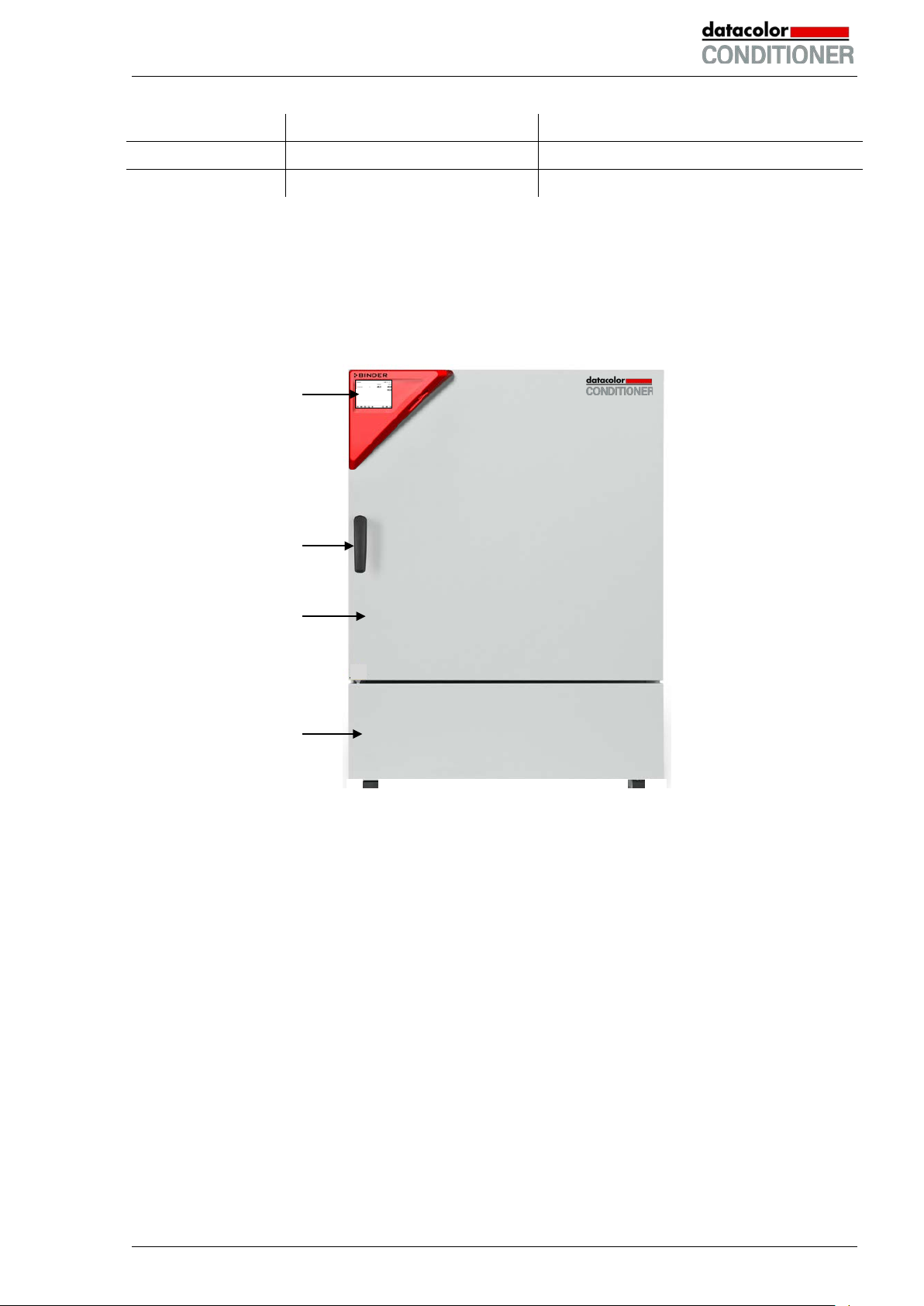
2.1 Cabinet overview
(B)
(C)
(D)
Figure 3: Datacolor CONDITIONER™ sample conditioning cabinet
(A) Instrument box
(B) Door handle
(C) Outer door
(D) Lower front cover: refrigerating machine and humidity generation module
Datacolor CONDITIONER™ (MB2) 06/2017 page 16/126
Page 17
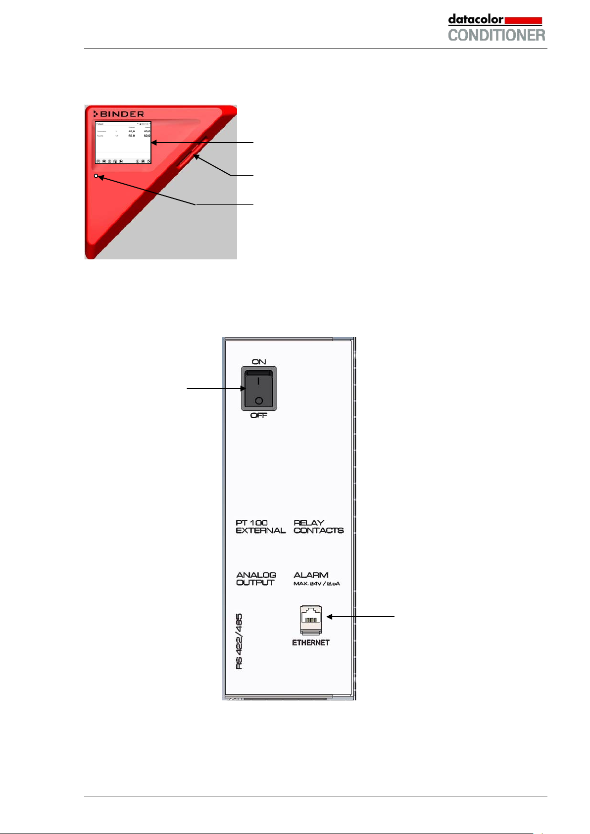
2.2 Instrument panel
5,7" controller display with touchscreen
USB interface
Pilot lamp
Figure 4: Instrument panel with MB2 program controller and USB interface
2.3 Lateral control panel
(1)
(2)
Figure 5: Lateral control panels at the right side of the refrigerating / humidity generation module
(1) Main power switch
(2) Ethernet interface
Datacolor CONDITIONER™ (MB2) 06/2017 page 17/126
Page 18
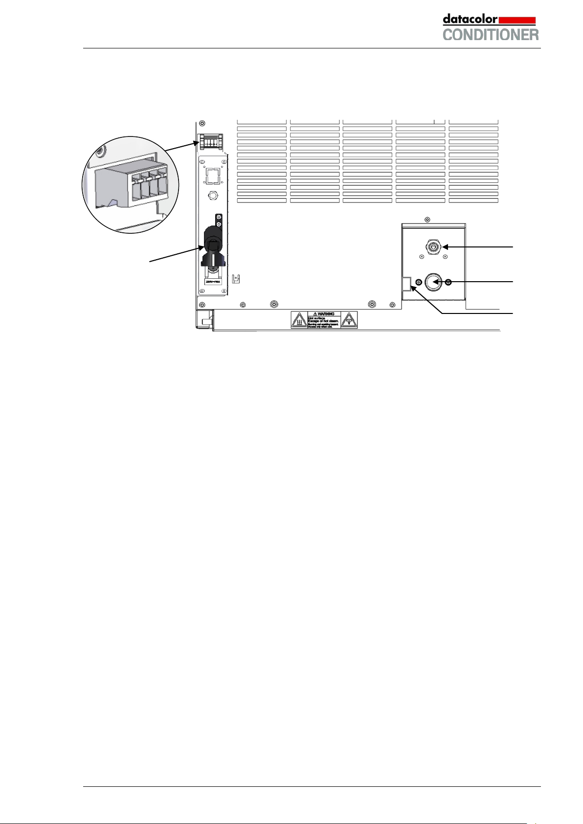
(3)
2.4 Rear view with water connections
(4)
Figure 6: Water connections on the cabinet rear
(3) Socket for optional freshwater can (chap. 4.5)
(4) Power cable
(5) Purging outlet for humidifying module – for service purpose only
(6) Freshwater connection “IN” with screw thread ¾’’ for hose ½“, with union nut
(7) Wastewater connection “OUT” with hose olive for hose ½“
(7)
(6)
(5)
Datacolor CONDITIONER™ (MB2) 06/2017 page 18/126
Page 19
3. Completeness of delivery, transportation, storage, and installa-
tion
3.1 Unpacking, and checking equipment and completeness of delivery
After unpacking, please check the cabinet and its optional accessories, if any, based on the delivery receipt for completeness and for transportation damage. Inform the carrier immediately if transportation
damage has occurred.
The final tests of the manufacturer may have caused traces of the shelves on the inner surfaces. This
has no impact on the function and performance of the cabinet.
Please remove any transportation protection devices and adhesives in/on the cabinet and on the doors
and remove the operating manuals and accessory equipment.
CAUTION
Sliding or tilting of the cabinet.
Damage to the cabinet.
Risk of injury by lifting heavy loads.
∅ Do NOT lift or transport the cabinet using the door, t he handl e, or the lower housing.
Lift the cabinet from the pallet at the four lower corners with the aid of four people
If you need to return the cabinet, please use the original packing and observe the guidelines for safe lifting and transportation (chap. 3.2).
For disposal of the transport packing, see chap. 21.1.
3.2 Guidelines for safe lifting and transportation
After operation, please observe the guidelines for temporarily decommissioning the cabinet (chap. 21.2).
CAUTION
Sliding or tilting of the cabinet.
Damage to the cabinet.
Risk of injury by lifting heavy loads.
Transport the cabinet in its original packaging only.
For moving or shipping, secure the cabinet with transport straps.
∅ Do NOT lift or transport the cabinet using the door, t he handl e, or the lower housing.
Lift the cabinet at the four lower corners with the aid of 4 people
You can order transport packing for moving or shipping purposes from your local Datacolor service representative.
Datacolor CONDITIONER™ (MB2) 06/2017 page 19/126
Page 20

CAUTION
midifying system must be activated (deactivated operation line “Humidity off”, chap.
) and close the tap of
Permissible ambient temperature range during transport:
• If the steam humidifying system has NOT been emptied: +3 °C / 37.4 °F to +60 °C / 140 °F.
• After your local Datacolor service representative has emptied the steam humidifying system: -10 °C /
14 °F to +60 °C / 140 °F.
At temperatures below +3 °C / 37.4 °F, water must be completely removed from the hum i difying system.
CAUTION
Transport below +3 °C / 37.4 °F with filled steam humidifying system.
Freezing in the steam generator.
Damage to the cabinet.
Contact your local Datacolor service representative before any transportation below +3
°C / 37.4 °F.
3.3 Storage
Intermediate storage of the cabinet is possible in a closed and dry room. Observe the guidelines for temporary decommissioning (chap. 21.2).
Permissible ambient temperature range during storage:
• If the steam humidifying system has NOT been emptied: +3 °C / 37.4 °F to +60 °C / 140 °F.
• After your local Datacolor service representative has emptied the steam humidifying system: -10 °C /
14 °F to +60 °C / 140 °F
With temperatures below +3 °C / 37.4 °F, water must be completely removed from the humidifying system.
CAUTION
Storage below +3 °C / 37.4 °F with filled steam humidifying system.
Freezing in the steam generator.
Damage to the cabinet.
Contact your local Datacolor service representative before any transportation below +3
°C / 37.4 °F.
Permissible ambient humidity: max. 70 % r.H., non-condensing
Condensation by excess humidity.
Danger of corrosion on the housing after operating at humidity values > 70 % r.H.
for a long period.
Dry the cabinet completely before shut-down:
• Set the humidity to 0 % r.H. To enable dehumidification, the humidifying and dehu-
7.3 and setting “Control on”, chap. 6.3).
• Set the temperature set point to 60 °C / 140 °F for approx. 2 hours (Manual mode).
• Only then, shut down the cabinet at the main power switch (1
the water supply.
When after storage in a cold location you transfer the cabinet to its warmer installation site, condensation
may form. Before start-up, wait at least one hour until the cabinet has attained ambient temperature and
is completely dry.
Datacolor CONDITIONER™ (MB2) 06/2017 page 20/126
Page 21
CAUTION
3.4 Location of installation and ambient conditions
Set up the cabinet on a flat, even surface, and in a well-ventilated, dry location and align it using a spirit
level. The site of installation must be capable of supporting the cabinet’s weight (see technical data, chap.
23.4). The cabinets are designed for setting up inside a building (indoor use).
Danger of overheating.
Damage to the cabinet.
∅ Do NOT set up cabinet in non-ventilated recesses.
Ensure sufficient ventilation for dispersal of the heat.
• Permissible ambient temperature range during operation: +18 °C / 64.4 °F to +32 °C / 89.6 °F. At
elevated ambient temperature values, fluctuations in temperature can occur.
The ambient temperature should not be substantially higher than the indicated ambient temperature of +22 °C +/- 3 °C / 71.6 °F ± 5.4 °F to which the specified technical data relate. Deviations from the indicated data are possible for other ambient conditions. Lower values of the
temperature range indicated in the technical data are valid at an ambient temperature of m ax.
25 °C / 77 °F.
With each degree of ambient temperature >25 °C / 77 °F, the refrigeration power decreases
by 1.5 K.
• Permissible ambient humidity: 70 % r.H. max., non-condensing
When operating the cabinet at temperature set-points below ambient temperature, high ambient humidity
may lead to condensation on the cabinet.
• Installation height: max. 2000 m / 6562 ft. above sea level.
A water tap (1 bar to 10 bar) is necessary for the installation of the humidificat i on sy st em (chap. 4.3). If no
suitable in-house water connection is available, you can manually supply water by filling the freshwater
can (option, chap. 4.5).
To avoid any possible water damage, provide a floor drain at the location of the device. Select
a suitable installation site to avoid any consequential damage by splashing water.
When placing several cabinets of the same size side by side, maintain a minimum distance of 250 mm /
9.84 in between each cabinet. Wall distances: rear 100 mm / 3.9 in, sides 160 mm / 6.29 in. Spacing
above the cabinet of at least 100 mm / 3.9 in must also be accounted for.
CAUTION
Danger by stacking.
Damage to the cabinets.
∅ Do NOT place the cabinets on top of each other.
To completely separate the cabinet from the power supply, you must disconnect the power plug. Install
the cabinet in a way that the power plug is easily accessible and can be easily pulled in case of danger.
For the user there is no risk of temporary overvoltages in the sense of EN 61010-1:2010.
With an increased amount of dust in the ambient air, clean the condenser fan (by suction or blowing)
several times a year.
Avoid any conductive dust in the ambiance according to the cabinet layout complying with pollution degree 2 (IEC 61010-1).
Datacolor CONDITIONER™ (MB2) 06/2017 page 21/126
Page 22
Do not install or operate the cabinet in potentially explosive areas.
DANGER
Explosion hazard.
Danger of death.
∅ Do NOT operate the cabinet in potentially ex pl osiv e areas.
KEEP explosive dust or air-solvent mixtures AWAY from the v i cinity of the cabinet.
After turning off the cabinet, you must close the tap of the water supply. Install the cabinet in a way that
the freshwater supply is easily accessible.
In case of a prolonged temporal decommissioning: Leave the cabinet door open or remove the access
port plugs.
4. Installation and connections
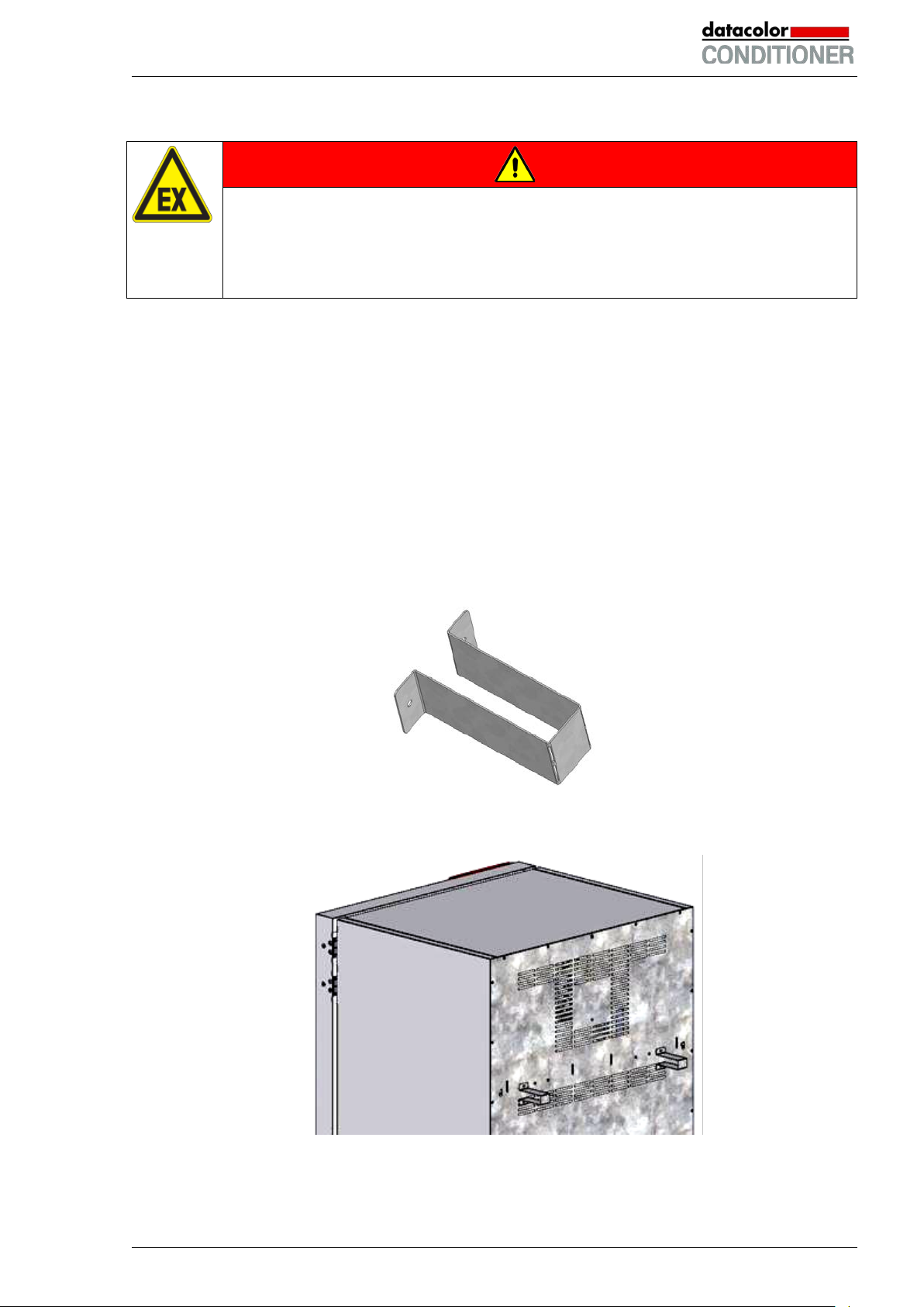
4.1 Spacer for wall distance
Please fix both spacers with the supplied screws at the cabinet rear. This serves to ensure the prescribed
minimum distance to the rear wall of 100 mm / 3.94 in.
Figure 7: Spacer for wall distance
Figure 8: Cabinet rear with mounted spacers
Datacolor CONDITIONER™ (MB2) 06/2017 page 22/126
Page 23

4.2 Wastewater connection
Fasten the wastewater hose to the wastewater connection “OUT” (7) on the rear of the cabinet (olive ∅
14 mm). Observe the following points:
• You can use a part of the supplied water hose as a drainage hose. In case another hose is used, it
has to be permanently resistant against at least 95 °C / 203 °F.
• Mount the wastewater hose with a maximum positive inclination of 1 m and a maximum total length of
3 m.
• Protect the cabinet end of the drainage hose with one of the supplied hose clamps.
• Reliably prevent sucking back of wastewater. The end of the wastewater hose must not be immersed
in liquids. This can be ensured e.g., by free discharge.
Waste water is collected in an internal can with a volume of approx. 0.5 liters. It i s pumped off
only when required, thus there is no continuous waste water flow.
Protect the waste water supply with the supplied hose clamps.
4.3 Freshwater supply
Connect the waste water pipe before connecting the cabinet to a freshwater pipe or filling the
freshwater can (option, chap. 4.5).
You can supply the cabinet with freshwater via a water pipe or by manually filling a freshwater can (option, chap. 4.5).
Water intake temperature NOT below +5 °C / 41 °F and not exceeding 40 °C / 104 °F.
CAUTION
Calcification of the humidifying system.
Damage to the cabinet.
Operate the cabinet with deionized (demineralized) water only.
Types of suitable water quality:
• Deionized water from a water treatment installation already existing at the customer's site. Conductivi-
ty from 1 µS /cm up to a maximum of 20 µS/cm. (Water, which is in equilibrium with the CO
and has a conductivity below 1 µS/cm (ultrapure water), may cause acid corrosion due to its low pH.)
in the air,
2
• Water treated by the optional water treatment system BINDER Pure Aqua Service (disposable sys-
tem). A reusable measuring equipment to assess the water quality is included (chap. 4.4).
The manufacturer is NOT responsible for the water quality at the user’s site.
Any problems and malfunctions that might arise following use of water of deviat i ng qual i ty is
excluded from liability by the manufacturer.
The warranty becomes void in the event of use of water of deviating quality.
Datacolor CONDITIONER™ (MB2) 06/2017 page 23/126
Page 24
For the water supply, fix the delivered adapter with hose olive on the thread at the rear of
4.3.1 Automatic fresh water supply via water pipe
An enclosure inside the cabinet contains the connection kit for freshwater and wastewater. Install the
freshwater connection using either the enclosed water hose or another pressure-resistant one. To accomplish this, remove the cover of the freshwater connection “IN” (6) on the rear of the cabinet. Protect
both ends of the hose with two of the four supplied hose clamps.
Before turning on the cabinet, check the connection for leaks. Water supply is automatically effected via
the freshwater connection “IN” (6).
As the appliance only lets in water when required, there is no continuous water flow.
• Supply pressure 1 to 10 bar when connecting to a water pipe
• Water type: deionized (demineralized) water
• Water intake temperature NOT below +5 °C / 41 °F and not exceeding 40 °C / 104 °F.
• The water intake should be provided with a shut-off slide or water-tap.
•
the cabinet.
• Protect the water supply at one side with the supplied hose clamp.
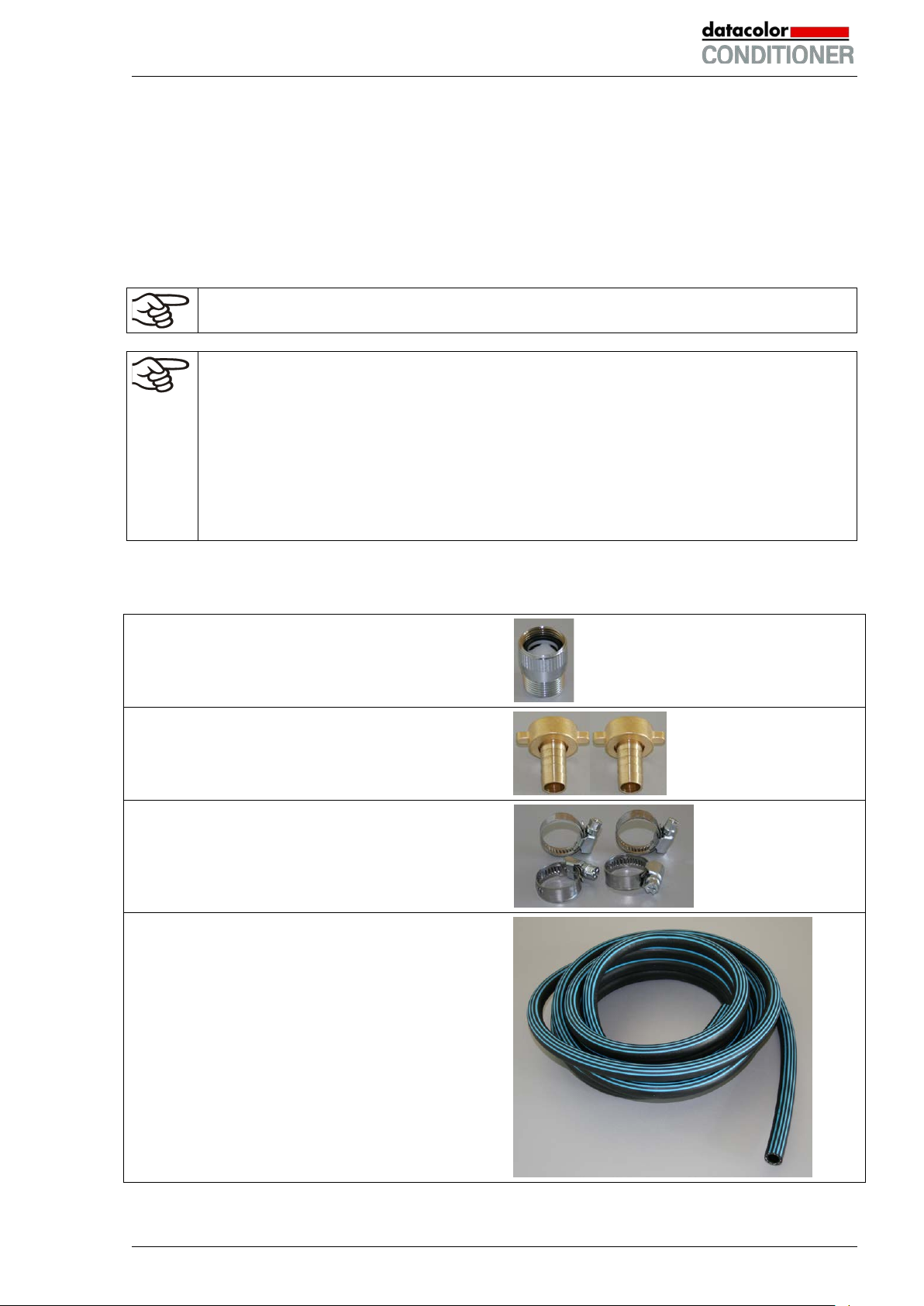
The connection kit for connecting the cabinet to the water main enclosed with the cabinet includes a
protective device against flooding caused by burst water hoses. Items supplied:
Hose burst protection device.
2 hose nozzles with screwing
4 hose clamps
6m water hose (PVC black, 12 mm (½’’) inner diameter), which should be cut into 2 accordingly, for the
feed hose and drain.
Pressure-resistant up to 10bar, heat resistant up to
95 °C / 203 °F.
Datacolor CONDITIONER™ (MB2) 06/2017 page 24/126
Page 25
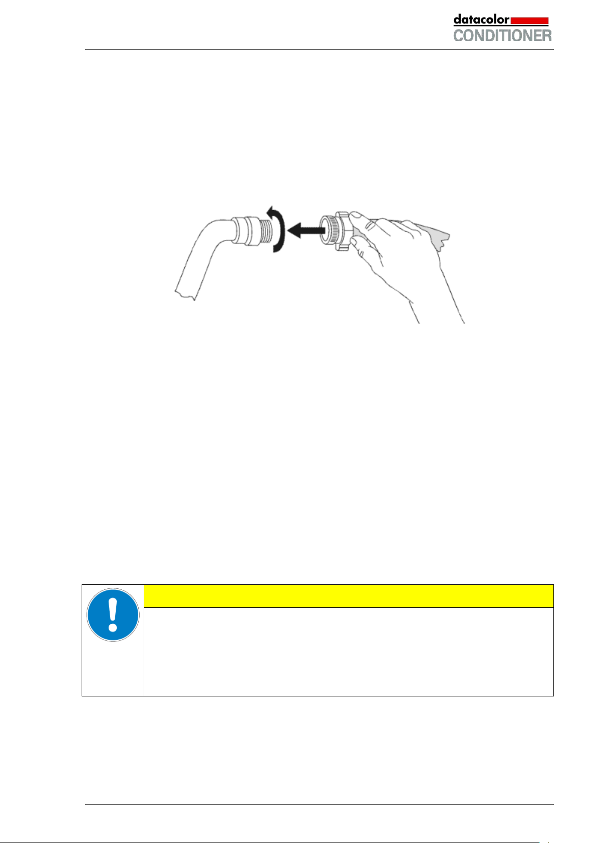
Assembly:
Screw the hose burst protection device onto a water tap with a G¾ inch right turning thread connection.
The connection is self-sealing. Establish the connection between the safety kit and the cabinet with a part
of the supplied hose. Protect both ends of the hose by the supplied hose clamps.
We recommend connecting the hose as the last step in order to avoid twisting the hose while screwing on
the safety kit.
Open the water tap slowly in order to avoid actuating the hose burst protection device.
Figure 9: Assembly of the connection kit
Protection principle of the hose burst protection device:
Whenever a strong water flow of about 18 l / min. occurs, e.g. caused by a burst water hose, a valve au-
tomatically cuts off the water supply, which can be heard as a clicking noise. The water supply now remains shut until it is manually released.
Release of the reflux protection device:
In case the burst protection device has interrupted the water supply, first find the reason and remove it as
necessary. Close the water tap. Release the valve by a half left-turn of the upper knurled part. You can
hear the release of the valve as a clicking noise. Tighten the burst protection device against the water tap
by a right turn. Open the water tap slowly afterwards.
Maintenance of the assembly of the hose burst protection device:
Calcification can impair valve function. We recommend an annual inspection by a skilled plumber. The
plumber should demount the safety kit to check the valve by hand for functi on, calcification or blockage.
CAUTION
Danger of calcification.
Impairment of valve function.
Have a plumber inspect the valve annually.
Remove calcifications by citric acid or acetic acid solutions.
Continue by testing the function and tightness of the mounted cabinet
Check: Quickly open the water tap while there is no cabinet connected – the valve should cut off the water flux without any delay.
Datacolor CONDITIONER™ (MB2) 06/2017 page 25/126
Page 26
4.3.2 Manual fresh water supply via external freshwater can (option)
If no house water connection with suitable water is available, you can manually supply water by filling a
freshwater can (volume: 20 liters / 0.71 cu.ft), which is part of the option “External freshwater and
wastewater cans” (chap. 4.5). You can attach the freshwater can on the rear of the cabinet or place it
next to the cabinet.
To guarantee humidification during 24 hours even at high humidity set-points with manual
water supply, we recommend filling the freshwater can (option) daily at the end of the day.
4.4 Optional water treatment system BINDER Pure Aqua Service
The optional water treatment system (disposable unit) is available to treat tap water. The lifetime of the
unit depends on water quality and the amount of treated water used. The measuring equipment to assess
the water quality is reusable.
For detailed information on installing and operating the water treatment system BINDER
Pure Aqua Service, please refer to the operating manual Art. No. 7001-0269, coming with
BINDER Pure Aqua Service.
4.5 Optional external freshwater and wastewater cans
If no suitable in-house water connection is available, you can manually supply water by filling the optional
external freshwater can. There is an additional external water can for the waste water. Volume: 20 liters /
0.71 cu.ft.
The cans are placed in holding devices. You can affix them directly at the rear of the cabinet or place
them next to the cabinet.
Figure 10: Cabinet rear view with installed external water cans (option)
Datacolor CONDITIONER™ (MB2) 06/2017 page 26/126
Page 27
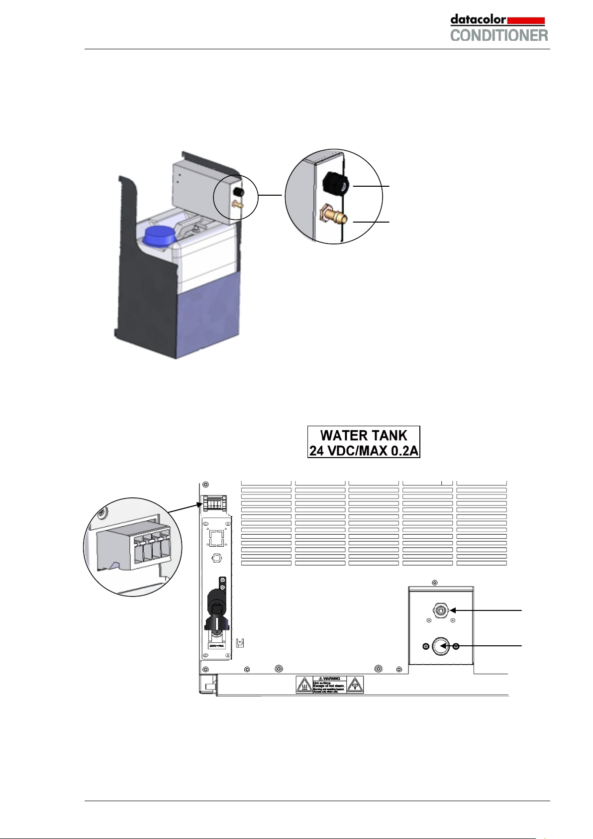
The socket (3) is marked with a sticker:
4.5.1 Mounting the freshwater can
(1) Fixing (if required)
Hang the can with its holding device on its 4 carriers. You can install it either at the left or the right
side.
Cable connection (8)
Freshwater hose connection (9)
Figure 11: Freshwater can (option)
(2) Cable connections
Connect the plug of the cable to the socket (3) at the rear of the cabinet.
Socket (3)
(7)
Datacolor CONDITIONER™ (MB2) 06/2017 page 27/126
(6)
Figure 12: Connections at the cabinet rear
Page 28
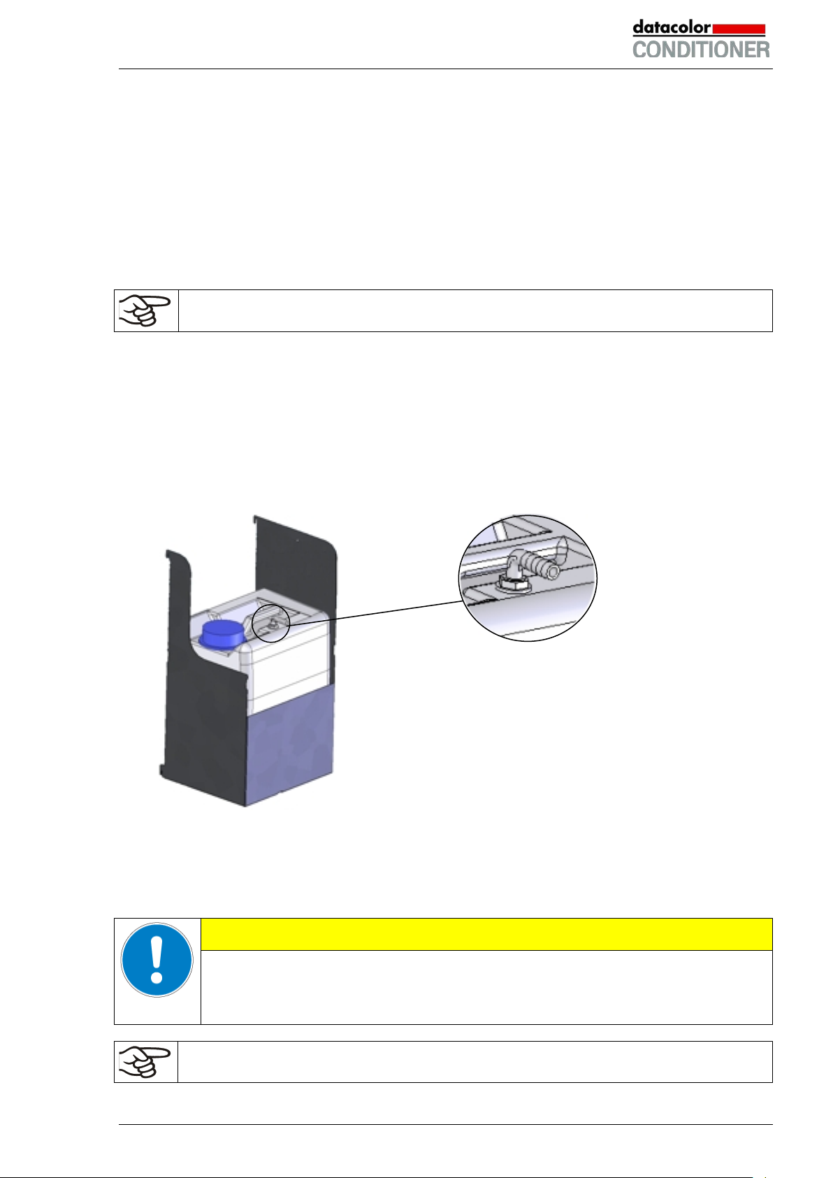
(3) Hose connections
Plug the freshwater hose into the hose connection (9) above the freshwater can and secure it with
a hose clamp. You can use a part of the standard supplied water hose.
Screw the hose nozzle (brass) to the free edge of the hose and screw it directly onto the freshwater connection “IN” (6) at the rear of the cabinet.
When the freshwater can is empty, the message “Freshwater supply” will be displayed on the controller
(chap. 11.1.3), the buzzer sounds, and the humidification module turns off. After acknowledging the
alarm, the humidification module tries to fill up and start operating.
To guarantee humidification during 24 hours even at high humidity set-points with manual
water supply, we recommend filling the freshwater can (option) at the end of each day.
4.5.2 Mounting the wastewater can
(1) Fixing (if required)
Hang the can with its holding device on its 4 carriers at the free space next to the freshwater can.
(2) Hose connections
Plug the wastewater hose to the hose connection (10) of the wastewater can and secure it with a
hose clamp. You can use a part of the standard supplied water hose.
Hose connection of the wastewater can (10)
Plug the free hose edge to the wastewater connection “OUT” (7) at the rear of the cabinet and secure it with a hose clamp.
Figure 13: Wastewater can (option)
You can remove the wastewater can with its holding device for emptying (disconnect the hose first before
emptying).
CAUTION
Overflow of the wastewater can.
Damage to the surrounding.
Empty the wastewater can in a timely manner before it is full.
Bringing a source of humidity into the inner chamber may increase wastewater production.
Regularly check the filling level of the wastewater can.
Datacolor CONDITIONER™ (MB2) 06/2017 page 28/126
Page 29

CAUTION
4.5.3 Mounting with wastewater recycling
When the cabinet interior is clean, you can reuse the wastewater from the cabinet. Connect the
wastewater connection “OUT” (7) of the cabinet with the freshwater hose connection (11) of the freshwater can. The wastewater can is not used in this case.
Soiling of the vapor humidification system.
Damage to the cabinet.
Reuse wastewater ONLY with a clean cabinet interior.
In case of soiling / contamination of the interior, conduct the wastewater to the
wastewater connection or use the wastewater can.
(1) Fixing of the freshwater can (if required)
Hang the can with its holding device on its 4 carriers. You can install it either at the left or the right
side.
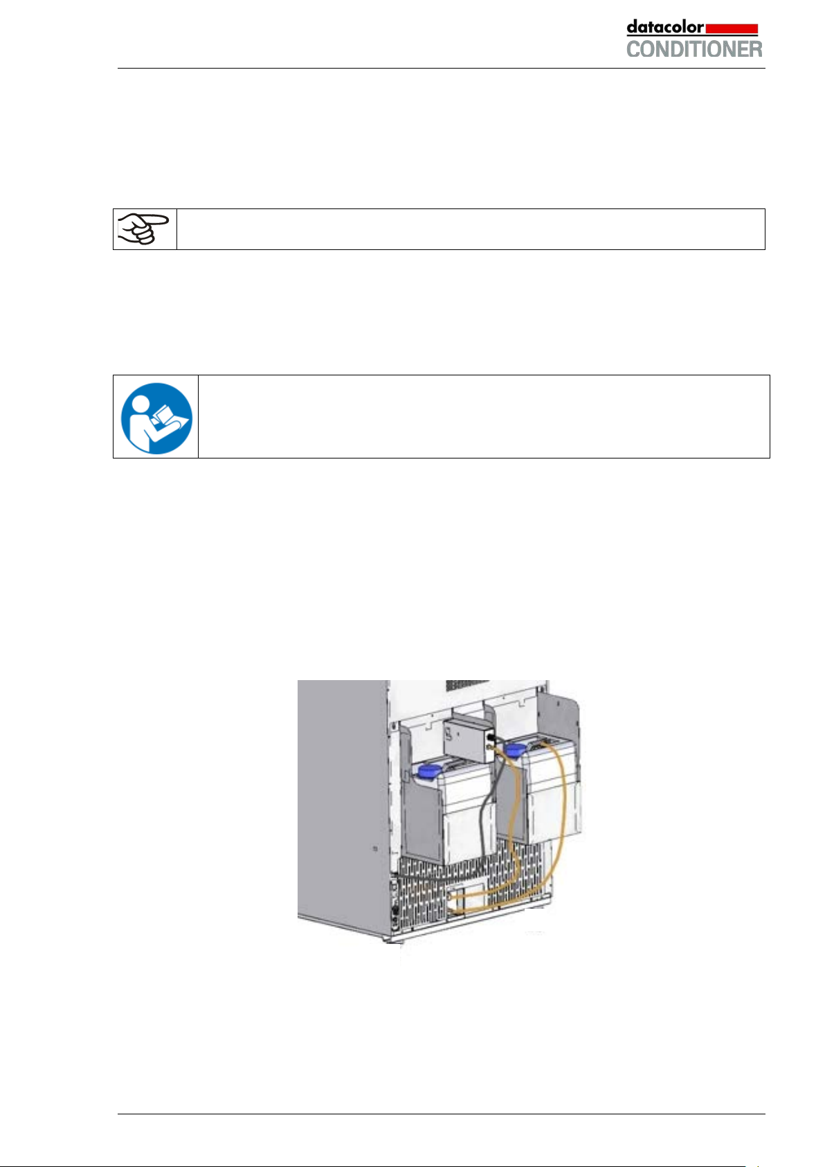
(2) Cable connections of the freshwater can
Connect the plug of the cable to the socket (3) at the rear of the cabinet as described in chap. 2.4.
(3) Hose connections
Plug the wastewater hose into the hose connection (11) of the freshwater can and secure it with a
hose clamp. You can use a part of the standard supplied water hose.
Plug the free hose edge to the wastewater connection “OUT” (7) at the rear of the cabinet and secure it with a hose clamp.
Hose connection of the freshwater can (11)
Figure 14: Freshwater can (option)
Bringing a source of humidity into the inner chamber may increase wastewater production.
Regularly check the filling level of the freshwater can.
Datacolor CONDITIONER™ (MB2) 06/2017 page 29/126
Page 30
4.6 Placement of the light cassettes (cabinet with lights)
The light cassettes are permanently connected. The cable length permits easily removal to replace the
fluorescent tubes or to change the position of the light cassette inside the cabinet.
You can insert the light cassettes in different heights onto the beads at the lateral walls of the chamber.
Insert and pull out the light cassettes only by the handles.
Do not place any charging material directly onto the light cassettes because those are heated by the fluorescent tubes which would lead to exposing the charging material to undefined temperatures. The temperature directly below or on the light cassettes is not equal to the temperature displayed at the temperature controller.
Place the charging material on the supplied racks below the light cassettes.
CAUTION
The light cassettes will become hot with temperature set-points >40 °C.
Danger of burning.
∅ Do NOT touch the light cassettes during operation.
Let the light cassettes cool down before changing their position.
4.7 Electrical connection
The cabinets are supplied ready for connection. They come with a fixed power connection cable of at
least 1800 mm / 70.87 in in length.
• Power plug: NEMA 6-20P
• Voltage +/-10% at the indicated power frequency: 200-240 V at 50Hz, 200-240 V at 60Hz
• Current type: 2~
• Cabinet fuse: 16 Amp
• The domestic socket must also provide a protective conductor. Make sure that the connection of the
protective conductor of the domestic installations to the cabinet’s protective conductor meets the latest
technology. The protective conductors of the socket and plug must be compatible!
• Prior to connection and start-up, check the power supply voltage. Compare the values to the specified
data located on the cabinet’s type plate (left cabinet side, bottom right -hand, see chap. 1.4).
• When connecting, please observe the regulations specified by the local electricity supply company.
We recommend the use of a residual current circuit breaker.
• Pollution degree (acc. to IEC 61010-1): 2
• Installation category (acc. to IEC 61010-1): II
CAUTION
Danger of incorrect power supply voltage.
Damage to the equipment.
Check the power supply voltage before connection and start-up.
Compare the power supply voltage with the data indicated on the type plate.
See also electrical data (chap. 23.4).
Datacolor CONDITIONER™ (MB2) 06/2017 page 30/126
Page 31

To completely separate the cabinet from the power supply, you must disconnect the power
plug. Install the cabinet in a way that the power plug is easily accessible and can be easily
pulled in case of danger.
Remark when operating the cabinet with a power frequency of 60 Hz:
WARNING
High leakage current.
Electrical hazard.
Earth connection is essential before connecting supply. Check socket before inserting
plug.
When connected to a power supply 1N~ with a frequency of 60 Hz, a leakage current of more than 3.5
mAmp is possible. If grounding through the power cable is insufficient or missing, the leakage current
may flow through the user’s body. Correct installation of the professional grade power socket provided by
the user safely avoids this. Before connecting the chamber to the socket, please check its grounding
contact type plug for appropriate construction and if it is undamaged.
4.8 Connection of the optional voltage changer
The voltage changer enables the cabinet to operate at a power frequency of 115 Volt. It is packed separately and supplied together with the cabinet.
The voltage changer is supplied with a fixed power connection cable with a NEMA 5-20P plug. It is protected against excess-current with an internal over-current release category B16A. The connection is
made by the customer.
CAUTION
Sliding or tilting of the voltage changer.
Damage to the voltage changer.
Risk of injury by lifting heavy loads.
Lift the voltage changer at both carrying handles from the pallet with two persons.
Do not install the voltage changer in the exhaust air flow at the rear of the cabinet.
For the installation of the voltage changer next to the cabinet, provide a wall distance the cabinet of ap-
prox. 0.4 m / 1.3 ft.
CAUTION
Danger of overheating.
Damage to the voltage changer.
∅ Do NOT install the voltage changer in unventilat ed recesses.
Ensure sufficient ventilation for dispersal of the heat.
Datacolor CONDITIONER™ (MB2) 06/2017 page 31/126
Page 32

Dimensions of the voltage changer
Width
mm
255
Depth (without door handles)
mm
360
Depth (incl. cable and door handles)
mm
450
Height
mm
300
Length of the connection cable to wall socket
mm
172
to set up the voltage changer (minimum)
Electrical connection data of the voltage changer
Input side V 115
A
26,9
Output side (to the cabinet)
V
214
A
13,0
Power frequency
Hz
50 / 60
(A)
(A) Carrying handle
(B) Pilot lamp (green)
(B)
(C)
(D)
(C) Power switch
(D) Connection socket for cabinet
(E) Power cable
Figure 15: Voltage changer (front)
(E)
To establish the electrical connection of the cabinet with the voltage changer, proceed in the following
order:
1. Connect the power cable of the cabinet to the connection socket (D) of the voltage changer
2. Establish the power connection of the voltage changer. The socket must provide a protective conduc-
tor.
3. Turn on the voltage changer at the power switch (C) (position “I”). The green pilot lamp (B) lights up.
4. Turn on the cabinet with the main power switch (1) in the lateral control panel
Position “0” = off Position “I” = on
Figure 16: Power switch of the voltage changer
Lateral wall clearance of the cabinet
Datacolor CONDITIONER™ (MB2) 06/2017 page 32/126
mm 400
Page 33

5. Functional overview of the MB2 chamber controller
The MB2 chamber controller controls following parameters inside the cabinet:
• Temperature in °C
• Relative humidity in % r.H.
• Light intensity (cabinet with lights) in %
• Fan speed in %
For the control ranges of temperature and humidity, see climatic diagrams (chap. 17).
You can enter the desired set point values in fixed value operation mode directly on the display surface or
via the setpoint menu. For program operation the controller offers programming week and time programs.
In addition there is a timer program available (stopwatch function).
The controller offers various notifications and alarm messages with visual and audible indication and
remote alarms via e-mail, an event list (trace file) and the graphical display of the measuring values in the
in der chart recorder view. The MB2 program controller permits programming temperature and humidity
cycles and also defining the light intensity (cabinet with lights), fan speed and special controller functions
for each program section. You can enter values or programs directly at the controller or use the APTCOM™ 3 DataControlSystem software (option) specially developed by BINDER.
Datacolor CONDITIONER™ (MB2) 06/2017 page 33/126
Page 34

Operating mode
Temperature values
Humidity values
Actual values
Set-point values
Functional icons
Figure 17: Normal display of the MB2 program controller (sample values), cabinet without lights
Operating mode
Temperature values
Humidity values
Light intensity values
Actual values
Set-point values
Functional icons
Figure 18: Normal display of the MB2 program controller (sample values), cabinet with lights
Datacolor CONDITIONER™ (MB2) 06/2017 page 34/126
Page 35

Current operating mode
Date, time, authorization level of
5.1 Operating functions in normal display
Text list for information icons
the logged-in user, memory
Quick setpoint entry
Continue to next screen
Back to Normal display
Information
Program start
Setpoint entry
Event list
Display of active alarms
Access to main menu
Figure 19: Operating functions of the MB2 controller in normal display (example values for cabinet with
lights)
Datacolor CONDITIONER™ (MB2) 06/2017 page 35/126
Page 36

5.2 Display views: Normal display, program display, chart-recorder display
Press the Change view icon to toggle between normal display, program display and chartrecorder display.
Press the Normal display icon to return from program display and chart recorder display back to
Normal display.
• Normal display (actual values / setpoint values)
(Cabinet without lights)
• Program display (example: time program)
• Chart recorder display
(Cabinet with lights)
(Cabinet without lights)
Datacolor CONDITIONER™ (MB2) 06/2017 page 36/126
(Cabinet with lights)
Page 37

Icon
Signification
Function
Icon
Signification
Function
5.3 Controller icons overview
Navigation icons in Normal display
Main menu
Alarm
Event list
Access from Normal display to the main menu
Access from Normal display to the list of active alarms
Access from Normal display to the event list
Access from Normal display to the setpoint entry menu: setpoint
Setpoint setting
Program start
Program pause
Program cancelling
Information
Normal display
Change view
entry for Fixed value operation, turning on/off humidity cont rol,
safety controller settings
Start a previously entered time or week program,
continue a paused time program
Pause a running time program
Cancel a running time or week program
Information on program operation, setpoints, actual values, and
the safety controller
Return from program display or chart recorder display to Normal
display
Toggle between Normal display, program display, and chart
recorder display
Functional icons in individual menus
Back
Update
Confirm
Close
Reset alarm
Change keyboard
Edit
Return from each menu to Normal display
Update the event list and alarm messages
Take over the entries and exit the menu / continue menu se-
quence.
Exit the menu / cancel menu sequence. Entries are not taken
over. When terminating a menu sequence, an information window appears, which must be confirmed.
Acknowledge the alarm and mute the buzzer.
Change between uppercase and lower case characters, digits
and special characters
Edit settings of time and week programs
Datacolor CONDITIONER™ (MB2) 06/2017 page 37/126
Page 38

Icon
Signification
Function
Icon
Text information
Condition
Symbol
Information
Functional icons in the chart recorder display
Show legend
Hide legend
Switch legend
Show indications
Hide indications
History display
Curve selection
Search
Zoom
Show scroll buttons
Hide scroll buttons
Show legend
Hide legend
Switch between legend pages
Show indication “Door open” (B2)
Hide indication “Door open” (B2)
Pause chart recorder and change to history display. Data recording
continues.
Go to “Curve selection” submenu in the history display
Go to “Search” submenu in the history display to select the required
instant
Go to “Zoom” submenu in the history display to select the zoom factor
Show scroll buttons in the history display to scroll to an instant
Hide scroll buttons in the history display to scroll to an instant
Information icons referring to chamber conditions
“Idle mode” Controller in Idle mode
“Temperature range” Current actual temperature v al ue outside the tolerance range
“Humidity range” Current actual humidity value outside the tolerance range
“Door open” Cabinet door is open
“Humidity off” The humidification / dehumidification system is turned off
Information icon in the touchscreen calibration menu
Remaining time to touch the display when calibrating the touchscreen.
Datacolor CONDITIONER™ (MB2) 06/2017 page 38/126
Page 39

5.4 Operating modes
The MB2 program controller operates in the following operating modes:
• Idle mode
The controller is not functional, i.e., there is no heating or refrigeration and no humidification or dehumidification. The fan is off. Cabinet with lights: The fluorescent tubes are off. The cabinet approximates ambient values.
You can activate and deactivate this operating mode with the “Idle mode” control contact in Fixed value operating mode (chap. 7.3), time program operation (chap. 9.7.3) and week program operation
(chap. 10.6.5).
• Fixed value operating mode
The controller operates as a fixed-point controller, i.e., set-points for temperature and humidity, fan
speed and light intensity (cabinet with lights) can be defined, which are then maintained until the next
manual change (chap. 7.1).
• Timer program operation
Stopwatch function: during an entered duration the controller constantly equilibrates to the setpoints
entered in Fixed value operation mode.
• Time program operation
An entered time program for temperature, humidity fan speed and light intensity (cabinet with lights is
running. The controller offers 25 program memory places with 100 program sections each. The total
number of program sections of all programs is unlimited
• Week program operation
An entered week program for temperature, humidity fan speed and light intensity (cabinet with lights is
running. The controller offers 5 program memory places with 100 switching points each. The switching
points can be distributed over all days of the week.
Datacolor CONDITIONER™ (MB2) 06/2017 page 39/126
Page 40

5.5 Controller menu structure
Use the navigation icons in the screen footer in Normal display to access the desired controller functions.
Normal display (cabinet without lights)
The available functions depend on the current authorization level “Service”, “Admin” or “User” (chap.
13.1). This is selected either during login or can be available without password protection.
Main menu: program settings, further information, “Service” submenu.
The “Settings” submenu allows general configuration of the controller.
List of active alarms
Access to the event list
Setpoint entry for Fixed value operation, turning on/off humidi ty control,
safety controller settings
Start/ pause/ cancel an already entered, respectively a running time
program or start / cancel an already entered, respectively a running
week program
Unless noted otherwise, the figures show the functional range, which is available for the user with “Admin” authorization level.
Normal display (cabinet with lights)
chap. 5.5.1
chap. 11
chap. 15.2
chap. 7, 6.3,
12.2
chap. 9.1,
9.2, 10.1
Datacolor CONDITIONER™ (MB2) 06/2017 page 40/126
Page 41

5.5.1 Main menu
The main menu provides access to the general configuration of the controller as well as to program entry
and the user administration. Additionally there are support functions like a contact page or the display
calibration depending on the available angle.
Press the Main menu icon to access the main menu from Normal Display.
Press the Back icon to return from each setting menu to Normal Display.
The main menu provides the following functions and submenus.
User management: login and logout, password management
Cabinet information chap. 15.2
“Settings” submenu (not visible for user with
“User” authorization level)
Program entry submenu for time and week
programs
“Service” submenu chap. 5.5.3
Datacolor service contact page chap. 15.1
Calibrating the touch screen chap. 14.4.2
Back to Normal Display
“Settings” submenu
• Settings of many general controller functions and network settings (chap. 14).
chap. 13
chap. 14
chap. 9 and 10
• Available only for users with “Service” and “Admin” authorization level
“Service” submenu
• Access to service data, controller reset to factory settings (chap. 5.5.3)
• Available only for users with “Service” and “Admin” authorization level. Full functional range only for
Datacolor service representatives (users with “Service” authorization level).
“Programs” submenu
• Access to the controller’s program functions (chap. 8, 9, 10)
Datacolor CONDITIONER™ (MB2) 06/2017 page 41/126
Page 42

Setting the temperature unit, menu language…
operation and screen saver
Settings for the measurement chart: storage
interval, storage values, min. and max. values
Setting the tolerance range and delay time for
tolerance range alarm
Configuration of the e-mail server, assignment of e-mail addresses
Information for your Datacolor service representative
5.5.2 “Settings” submenu
The “Settings” submenu is available for users with “Service” or “Admin” authorization level. It serves to
enter date and time, select the language for the controller menus and the desired temperature unit and to
configure the controller’s communication functions.
Path: Main menu > Settings
chap. 14.1, 14.2
Setting date and time chap. 14.3
Setting the display brightness, continuous
Entry of the MAC address and IP address chap. 14.5.1
Password protection for web server access chap. 14.5.2
Back to main menu
chap. 14.4
chap. 16.2
chap. 11.4
chap. 14.5.3
5.5.3 “Service” submenu
The “Service” submenu is available for users with “Service” or “Admin” authorization level. When loggedin with “Admin” authorization level the user will find information to tell your local Datacolor service representative in service case.
Path: Main menu > Service
(view with “Admin” authorization level)
Datacolor CONDITIONER™ (MB2) 06/2017 page 42/126
Serial number of the cabinet, setup version of
the controller software
Counter of operating hours chap. 15.4
Reset to factory settings
Back to main menu
chap. 14.2
Page 43

5.6 Principle of controller entries
In the selection and entry menus there are icons displayed in the footers which you can use to take over
the entry or cancel it.
Selection menu (example)
After completing the settings there are the following possibilities:
Press the Confirm icon to take over the entries and exit the menu or continue the menu sequence.
Press the Close icon to exit the menu or cancel the menu sequence without taking over the entries.
When terminating a menu sequence, an information window appears, which must be confirmed.
Entry menu (example)
5.7 Performance during and after power failures
During a power failure, all controller functions are shut down.
After the power returns, all functions return to the same status the cabinet had before power failure. . The
controller continues to function in the original operating mode it was in previously before the power failure
occurred.
• Performance after power failure in Idle mode
Control is deactivated
• Performance after power failure in Fixed value operation mode
All functions return to the same status the cabinet had before power failure. The set-points are immediately resumed.
• Performance after power failure during time program operation
The program is resumed at the point where the interruption occurred with the latest set-points reached
during the program run.
• Performance after power failure during week program operation
The week program continues with the values corresponding to the current time.
Power failure and power return are noted in the event list (chap. 15.3).
If during power failure an alarm has occurred (tolerance range, safety controller), confirm the alarm. See
chap. 11.3.
Datacolor CONDITIONER™ (MB2) 06/2017 page 43/126
Page 44

5.8 Performance when opening the door
When you open the door the fan starts running with minimum speed.
After 60 seconds from opening the door, heating, refrigeration, humidification, dehumidification and fan
turn off.
After closing the door, heating, refrigeration, humidification, dehumidif icat i on and fan turn on again.
6. Start up
6.1 Turning on the cabinet
After connecting the supply lines (chap. 4), turn on the cabinet by its main power switch (1). The lit pilot
lamp shows the cabinet is ready for operation.
When the main power switch is turned on and yet the controller display is dark, the display is in stand-by
mode. Press on the touchscreen to activate it.
• Open the water-tap for freshwater supply. Alternatively, f i l l the freshwater can (option, chap. 4.5).
• The humidifying and dehumidifying system must be activated (deactivated operation line “Humidity
off”, chap. 7.3 and setting “Control on”, chap. 6.3).
After the first turning on of the cabinet or after an interruption of the power supply the relative humidity will
increase after a delay of about 20 minutes, as the fresh water needs to be heated first. During this period,
the relative humidity can drop considerably.
The cabinet may release odors in the first few days after commissioning. This is not a quality defect. To
reduce odors quickly we recommend heating up the cabinet to its nominal temperature for one day and in
a well-ventilated location.
WARNING: If customer should use a cabinet running in non-supervised continuous operation, we strongly recommend in case of inclusion of irrecoverable specimen or samples to
split such specimen or samples and store them in at least two cabinets, if this is feasible.
6.2 Controller settings upon start up
The window „Language selection“ enables the language selection, in case that it’s activated in the
“Start-up” menu. Afterwards occurs a request of the time zone and the temperature unit.
The controller will function in the operating mode, which was active before the last shut-down. It controls
temperature and humidity in fixed value operating mode to the last entered values and in the program
mode to the set points achieved beforehand.
Datacolor CONDITIONER™ (MB2) 06/2017 page 44/126
Page 45

Locked operation
Provided that the user administration has been activated by the assignment of passwords for the different
authorization types, the controller operation is first locked after turning on the unit, recognizable by the
closed lock icon in the header.
In the locked view the controller provides all display functions. No setting functions are av ail abl e.
The setpoints are shaded (light grey) in normal display. Changing them by direct entry in the fixed value
operating mode is not possible. The functional icons for setpoint entry and program start in the footer are
without function.
After turning on the unit, user log-in is required to operate the controller (chap. 13.2)
Operation without user log-in / without password-protection
If the password function has been deactivated, after turning on the unit without user log-in there are those
controller functions available, which correspond to the highest authorization level without a password
protection. There is no lock icon in the header.
6.3 Turning on/off humidity control
Turning off humidity control is required when operating the cabinet without water connection in order to
avoid humidity alarms. For further information see chap. 17.
Press the Setpoint setting icon to access the “Setpoint” setting menu from Normal display.
“Setpoints” menu.
Select “Control on/off”.
Datacolor CONDITIONER™ (MB2) 06/2017 page 45/126
You can turn humidity control (humidification
and dehumidification) on or off.
If the “Humidity “checkbox is marked, humidity
control is active. Mark / unmark the checkbox
to change the setting.
Page 46

7. Set-point entry in “Fixed value” operating mode
In Fixed value operating mode you can enter a temperature set-point, a humidity set-point, the fan speed,
and the switching-state of up to 16 operation lines.
All settings made in Fixed value operating mode remain valid until the next manual change. They are
saved also when turning off the cabinet or in case of toggling to Idle Mode or Program Mode.
Cabinet without
lights
Temperature
Humidity
Fan speed
Cabinet with
lights
Temperature
Humidity
Light intensity
Fan speed
Reduce the fan speed only if required, because the spatial distribution of temperature and
humidity will also be reduced.
Technical data refers to 100% fan speed.
Setting ranges Control ranges
0 ºC / 32 °F up to 70 °C / 158 °F without humidity
-5 °C / 41 °F up to 70 °C / 158 °F.
10 °C / 50 °F up to 70 °C / 158 °F with humidity
10 % r.H. to 80 % r.H.
0 % r.H. up to 80 % r.H.
see climatic diagrams, chap. 17.
40% up to 100 %
Setting ranges Control ranges
0 ºC / 32 °F up to 50 °C / 122 °F without humidity
-5 °C / 41 °F up to 50 °C / 122 °F.
10 °C / 50 °F up to 50 °C / 122 °F with humidity
10 % r.H. to 70 % r.H.
0 % r.H. up to 70 % r.H.
see climatic diagrams, chap. 17.
0 % to 100 %
40% up to 100 %
For the control range of temperature and relative humidity, see the temperature / humidit y diagrams chap.
17).
With set-point type “Limit”, adapt the safety controller (chap. 12.2) always when you changed
the temperature set-point. Set the safety controller set-point by approx. 2 °C to 5 °C above the
controller temperature set-point.
Recommended setting: Set-point type “Offset” with safety controller set-point 2 °C.
When operating without humidity by setting “Control off” (chap. 6.3), the humidity tolerance
range function is automatically deactivated.
When operating without humidity by activated operation line “Humidity off” (chap. 7.3), set the
humidity tolerance range to “0” in order to avoid tolerance range alarms (chap. 11.4).
Datacolor CONDITIONER™ (MB2) 06/2017 page 46/126
Page 47

7.1 Set-point entry for temperature, humidity, light intensity, and fan speed
through the “Setpoints” menu
Press the Setpoint setting icon to access the “Setpoint” setting menu from Normal display.
“Setpoints” menu (cabinet without lights) “Setpoints” menu (cabinet with lights)
Select “Fixed value operation setpoints” to access the individual parameters.
• Select the field “Temperature” and enter the desired temperature setpoint.
Cabinet without lights: Setting range: -5 °C up to 70 °C.
Cabinet with lights: Setting range: -5 °C up to 50 °C.
Confirm entry with Confirm icon.
• Select the field “Humidity” and enter the desired humidity setpoint.
Cabinet without lights: Setting range: 0% r.H. up to 80% r.H.
Cabinet with lights: Setting range: 0% r.H. up to 70% r.H.
Confirm entry with Confirm icon.
• Select the field “Fan” and enter the desired fan speed setpoint.
Setting range: 40% up to 100% fan speed.
Confirm entry with Confirm icon.
• Cabinet with lights: Select the field “Light” and enter the desired light intensity setpoint.
Setting range: 0% up to 100% light intensity. With setting 0% t he l i ght is off.
Confirm entry with Confirm icon.
When entering a value outside the setting range, the message: “Value outside of limits! (Min:
xxx, Max: xxx)” appears (xxx is a wildcard for the limits of the respective parameter). Press the
Confirm icon and repeat the entry with a correct value.
After completing the settings, press the Confirm icon to take over the entries and exit the menu, or press
the Close icon to exit the menu without taking over the entries.
Datacolor CONDITIONER™ (MB2) 06/2017 page 47/126
Page 48

7.2 Direct setpoint entry for temperature, humidity, and light intensity via
Normal display
Alternatively you can also enter the setpoints directly via Normal display.
Normal display (example: cabinet with lights)
Select the setpoint you want to change.
Example: “Temperature” entry menu. Enter the desired setpoint and confirm entry with Confirm icon.
7.3 Special controller functions via operation lines
Press the Setpoint setting icon to access the “Setpoint” setting menu from Normal display.
You can define the switching state of up to 16 operation lines (control contacts). They are used to activate
/ deactivate special controller functions.
• Operation line “Humidity off” serves to turn off the humidity.
• Operation line Idle mode” activates / deactivates the operating mode “Idle mode”.
The other operation lines are without function.
Use the “Setpoints” menu to configure the operation lines.
“Setpoints” menu (example: cabinet with lights)
Select the field “Functions on/off”.
Activated operation line: switching status “1” (On), deactivated operation line: switching status “0” (Off )
The operation lines count from right to left. Example:
Activated operation line “Humidity off” = 000000000000000
Deactivated operation line “Humidity off” = 000000000000000
Datacolor CONDITIONER™ (MB2) 06/2017 page 48/126
“Functions on/off” entry menu.
Mark / unmark the checkbox to activate / deac-
tivate the desired function.
1
0
Page 49

8. Timer program: stopwatch function
During an entered duration the controller constantly equilibrates to the setpoints entered in Fixed value
operation mode (temperature, humidity, fan speed, configuration of the operation lines). This duration can
be entered as a “Timer program”. During the program runtime, any setpoint changes do not become effective; the controller equilibrates to the values which were active during program start.
8.1 Starting a timer program
In Normal display press the Program start icon to access the “Program start” menu.
“Program start” menu.
• In the field “Program type” select “Timer program”.
• Select the field “Program duration” and enter the desired program duration. Press the Confirm icon.
• Select the field “Program start” and enter the desired start time of the program. Press the Confirm
icon. The program delay time until program start begins.
Normal display.
Information on the bottom of the screen indicates the
currently running program and the time already passed.
The grey bar shows how much time of the whole time is
elapsed.
8.1.1 Performance during program delay time
During the configured program delay time until program start, the controller equilibrates to the current
setpoints of Fixed value operation mode. Modifications of these setpoints are possible but become effective only after the timer program is finished. When the configured moment for program start is reached,
the program delay time ends and the program starts running. The controller equilibrates to the values
which had been active during program start
Datacolor CONDITIONER™ (MB2) 06/2017 page 49/126
Page 50

8.2 Stopping a running timer program
8.2.1 Pausing a running timer program
Press the Program pause icon to interrupt the program.
The program is paused. The program runtime stops running down, the time display flashes.
There are the following options:
Press the Program start icon to continue the program
Press the Cancelling icon to cancel the program
8.2.2 Cancelling a running timer program
Press the Program cancelling icon to cancel the program.
A confirmation prompt is displayed.
Press the Confirm icon to confirm that the program shall really be cancelled.
After confirming the message the controller changes to Fixed value operation mode. Temperature and
humidity will then equilibrate to the setpoints of Fixed value operat i on m ode.
8.3 Performance after the end of the program
After the end of the program the message “Device
changes to fixed value operation mode” appears on the
screen.
Press the Confirm icon.
After confirming the message the controller changes to Fixed value operation mode. Temperature and
humidity will then equilibrate to the setpoints of Fixed value operat ion m ode.
Datacolor CONDITIONER™ (MB2) 06/2017 page 50/126
Page 51

9. Time programs
The MB2 program controller permits programming time programs with real-time reference. It offers 25
program memory positions with up to 100 program sections each.
For each program section you can enter a temperature set-point, fan speed, section duration, type of
temperature transition (ramp or step) and the tolerance range.
If the safety controller has been set to “limit” mode, check the setting of the safety controller
when changing the temperature set-point, (chap. 12.2).
Reduce the fan speed only if required, because the spatial distribution of temperature and
humidity will also be reduced.
Technical data refers to 100% fan speed.
Programming remains saved in case of a power failure or after turning off the unit.
Path: Main menu > Programs> Time program
9.1 Starting an existing time program
In Normal display press the Program start icon to access the “Program start” menu.
“Program start” menu
• In the field “Program type” select the setting “Time program”.
• In the field “Program” select the desired program.
• Select the field “Program start” and enter the desired program start time. Press the Confirm icon. The
program delay time until program start begins.
The program end is adapted automatically depending on the entered program duration.
After completing the settings, press the Confirm icon to take over the entries and exit the menu. The
program starts running.
If instead you press the Close icon to exit the menu without taking over the entries, the program will not
start.
Normal display. Information on the bottom of the screen
indicates the currently running program and the time already passed. The grey bar shows how much time of the
whole time is elapsed. If program duration has been set to
infinite, the grey bar is not displayed.
Datacolor CONDITIONER™ (MB2) 06/2017 page 51/126
Page 52

9.1.1 Performance during program delay time
During the configured program delay time until program start, the controller equilibrates to the current
setpoints of Fixed value operation mode. Modifications of these setpoints are effective. When the configured moment for program start is reached, the program delay time ends and the program starts running.
9.2 Stopping a running time program
9.2.1 Pausing a running time program
Press the Program pause icon to interrupt the program..
The program is paused. The program runtime stops running down, the time display flashes.
There are the following options:
Press the Program start icon to continue the program
Press the Cancelling icon to cancel the program
9.2.2 Cancelling a running time program
Press the Program cancelling icon to cancel the program.
A confirmation prompt is displayed. Press the Confirm icon to confirm that the program shall really be
cancelled.
After confirming the message, the controller changes to Fixed value operation mode. Temperature and
humidity will then equilibrate to the setpoints of Fixed value operat i on m ode.
9.3 Performance after the end of the program
After the end of the program the message
“Device changes to fixed value operation
mode” appears on the screen.
Press the Confirm icon.
As long as the message has not been confirmed, the setpoint of the last program section remains effective. Program the last section as desired. If e.g. heating, refrigeration, humidification an dehumidification
shall turn off, activate operation line “Idle mode” in the last program section.
After confirming the message the controller changes to Fixed value operation mode. Temperature and
humidity will then equilibrate to the setpoints of Fixed value operat ion m ode.
Datacolor CONDITIONER™ (MB2) 06/2017 page 52/126
Page 53

Select a program section to open the
9.4 Creating a new time program
Path: Main menu > Programs > Time program
“Time program” menu:
overview of the existing programs.
Select an empty program place.
Enter the program name and, if desired, additional program information in the corresponding
fields.
Press the Confirm icon.
The program view opens (chap. 9.5).
9.5 Program editor: program management
Path: Main menu > Programs > Time program
“Time program” menu:
overview of the existing programs.
Select an existing program (example: program
3) or create a new program (chap. 9.4).
The program view opens.
Datacolor CONDITIONER™ (MB2) 06/2017 page 53/126
Program view (example for cabinet with lights:
program 3).
If a new program has been created, there is
just one program section.
There are the following options:
section editor (chap. 9.6)
Press the Edit icon to open the program
editor
Page 54

Program editor: “Edit program” menu
Select the desired function and press the Confirm
icon.
The program editor offers following options:
• Change the program name
• Copy program
• Replace program: Replacing an new or an existing program with the copied program. This menu point
is visible only after a program has been copied.
• Delete program
• Add new section
To add a new section, select “Add new section” and press the Confirm icon.
The program view opens.
9.5.1 Deleting a time program
Program view (example: cabinet with lights).
A new section is always added at the very bot-
tom (example: section 2).
Path: Main menu > Programs > Time program
In the “Time program” menu select the program to be deleted. The program view opens.
In the program view press the Edit icon to open the program editor
In the program editor select “Delete program” and press the Confirm icon.
The program is deleted. The controller returns to the program view.
Datacolor CONDITIONER™ (MB2) 06/2017 page 54/126
Page 55

9.6 Section editor: section management
Path: Main menu > Programs > Time program
Select the desired program.
Program view (example: cabinet with lights).
Select the desired program section
(example: section 1)
Section view (example: section 1).
There are the following options:
Select a parameter to enter or modify t he
according value (chap. 9.7)
Press the Edit icon to open the program
editor
Section editor: “Edit section” menu
Select the desired function and press the Confirm icon.
The section editor offers following options:
• Copy section
• Replace section: Replacing an existing section with the copied section. This menu point is visible only
after a section has been copied.
• Insert section: Adding the copied section. This menu point is visible only after a section has been cop-
ied.
• Delete section
• Add new section
Datacolor CONDITIONER™ (MB2) 06/2017 page 55/126
Page 56

Section editor: “Edit section” menu.
9.6.1 Add a new program section
Select “Add new section” and press the Confirm
icon.
Then select whether to insert the new section
before or after the current section.
Press the Confirm icon. The new section opens.
9.6.2 Copy and insert or replace a program section
Program view (example: cabinet with lights).
Select the program section to be copied
(example: section 1)
Section view (example: section 1).
Press the Edit icon to open the section editor.
Section editor: “Edit section” menu
Select “Copy section” and press the Confirm
icon.
The current section (example: section 1) is
copied.
The controller returns to the section view.
Datacolor CONDITIONER™ (MB2) 06/2017 page 56/126
Section view (example: section 1).
Press the Close icon to change to the pro-
gram view, if you want to select another section to be replaced or before or after which
the copied section shall be inserted…
Page 57

or
Press the Edit icon to open the section editor
if you want the current section to be replaced
or the copied section to be inserted before or
after it
Program view (example: cabinet with lights).
Select the section to be replaced or before or
after which the copied section shall be inserted (example: section 2) and press the Con-
firm icon.
Section view (example: section 1).
Press the Edit icon to open the section editor
Select “Replace section” to replace the selected section
with the copied section
or
Select “Insert section” to additionally add the copied
section.
In this case select whether to insert it before or after the
selected section.
Section editor: “Edit section” menu
Press the Confirm icon
9.6.3 Deleting a program section
In the program view select the program section to be deleted. The section view opens.
In the section view press the Edit icon to open the section editor
In the section editor select “Delete section” and press the Confirm icon.
The section is deleted. The controller returns to the section view.
Datacolor CONDITIONER™ (MB2) 06/2017 page 57/126
Page 58

Section duration
Type of setpoint transition: ramp or step
Operation lines
Temperature setpoint
Humidity setpoint
Fan speed
9.7 Value entry for a program section
Path: Main menu > Programs > Time program
Select the desired program and section.
The section view gives access to all parameters of a program section. You can enter or modify the val-
ues.
Program name and section number
Repeating one or several sections within a program
Temperature tolerance range: minimum and maximum
Humidity tolerance range: minimum and maximum
The setting and control ranges for the individual parameters are the same as for “Fixed value” operating
mode (chap. 7).
9.7.1 Section duration
Section view (partial view).
Select the field “Duration” indicating the time.
“Duration” entry menu.
Enter the desired section duration with the arrow keys
and press the Confirm icon.
Setting range: 0 up to 99 hours 59 min 59 sec.
Datacolor CONDITIONER™ (MB2) 06/2017 page 58/126
Page 59

9.7.2 Set-point ramp and set-point step
You can define the type of temperature and humidity transitions for each indiv i dual program secti on.
“Ramp” mode: Gradual changes of temperature and humidity
The set-point of a given program section functions as the section’s start temperature. During the section’s
duration, the set-point gradually passes to the set-point of the subsequent program section. The actual
value follows the continually changing set-point.
If the last program section is in “ramp” mode and the setpoint shall change within this section, then you
must program an additional section (with the shortest possible section duration) to provide the target
temperature of the last program section. Otherwise, the setpoint would remain constant during the section’s duration.
Programming in the “ramp” mode allows all kinds of temperature and humidity transitions:
• Gradual changes of temperature and humidity
The setpoint changes its value gradually during the entered section duration. The actual value follows
the continually moving set-point at any time.
• Program sections with constant temperature and humidity
The setpoints (initial values) of two subsequent program sections are identical; so the temperature
and humidity remain constant during the entire duration of the first program section.
• Sudden changes of temperature and humidity
Steps can be programmed in ramp mode as temperature or humidity changes (ramps) that occur during a very short interval. If the duration of this transitional program section is very short (minimum entry 1 sec), the temperature or humidity change will proceed rapidly within the minimum am ount of time.
“Step” mode: Sudden changes of temperature and humidity
The set-point of any program section functions as the section’s target value. At the start of the program
section, the cabinet heats up or cools down and humidifies/dehumidifies with the maximum speed to
reach the entered value; and then it holds it for the remaining section time. Therefore the set-point temperature remains constant for the section’s duration. These changes occur rapidly within the minimum
amount of time (minimum entry: 1 second).
Programming in the “step” mode allows only two kinds of temperature and humidity transitions:
• Programming gradual changes of temperature and humidity (ramps) is impossible in the “step” mode
• Program sections with constant temperature and humidity
The setpoints (target values) of two subsequent program sections are identical; so the temperature
and humidity remain constant during the entire duration of the first program section.
• Sudden changes of temperature and humidity
The entered setpoint of the section is reached as fast as possible and then held constant for the remaining section duration.
Selecting the setting “Ramp” or “Step”
Section view (partial view).
In the field “Course” select the desired setting
“Ramp” or “Step”.
Datacolor CONDITIONER™ (MB2) 06/2017 page 59/126
Page 60

W/°C
t/min.
0
20
40
60
80
100
10 30 40
60 70 100
130
1 2 3 4 5 6 7 8
[hh:mm:ss]
[°C]
[% rH]
[%]
1
00:10:00
40.0
xxxx
xxxx
Step
2
00:20:00
60.0
xxxx
xxxx
Step
3
00:10:00
80.0
xxxx
xxxx
Step
4
00:20:00
40.0
xxxx
xxxx
Step
5
00:10:00
40.0
xxxx
xxxx
Ramp
6
00:30:00
80.0
xxxx
xxxx
Ramp
7
00:30:00
80.0
xxxx
xxxx
Ramp
8
00:00:01
20.0
xxxx
xxxx
Ramp
The controller returns to the section view.
“Ramp” and “Step” mode example (representation of a temperature course)
Corresponding program table
Section No.
Duration
Temperature
Humidity
Fan
Ramp or Step
9.7.3 Special controller functions via operation lines
You can define the switching state of up to 16 operation lines (control contacts). They are used to activate
/ deactivate special controller functions.
• Operation line “Humidity off” serves to turn off the humidity.
• Operation line Idle mode” activates / deactivates the operating mode “Idle mode”.
The other operation lines are without function.
Use the Section editor to configure the operation lines.
Section view.
Select the field “Functions on/off”.
Datacolor CONDITIONER™ (MB2) 06/2017 page 60/126
“Functions on/off” entry menu.
Mark / unmark the checkbox of the desired
function to activate / deactivate it and press the
Confirm icon.
Page 61

Section view indicating the operation lines.
Activated operation line: switching status “1” (On)
Deactivated operation line: switching status “0” (Off)
The operation lines count from right to left.
Example:
Activated operation line “Humidity off” = 000000000000000
Deactivated operation line “Humidity off” = 000000000000000
1
0
9.7.4 Setpoint entry
• Select the field “Temperature” and enter the desired temperature setpoint.
Cabinet without lights: Setting range: -5 °C up to 70 °C.
Cabinet with lights: Setting range: -5 °C up to 50 °C.
Confirm entry with Confirm icon. The controller returns to the section view.
• Select the field “Humidity” and enter the desired humidity setpoint.
Cabinet without lights: Setting range: 0% r.H. up to 80% r.H.
Cabinet with lights: Setting range: 0% r.H. up to 70% r.H.
Confirm entry with Confirm icon. The controller returns to the section view.
• Select the field “Fan” and enter the desired fan speed setpoint.
Setting range: 40% up to 100% fan speed.
Confirm entry with Confirm icon. The controller returns to the section view.
• Cabinet with lights: Select the field “Light” and enter the desired light intensity setpoint.
Setting range: 0% up to 100% light intensity. With setting 0% the li ght is off.
Confirm entry with Confirm icon. The controller returns to the section view.
9.7.5 Tolerance range
You can specify a temperature and humidity program tolerance range for each program section with different values for the tolerance minimum and maximum. When the actual value exceeds the given threshold, the program is interrupted. This is indicated on the display (see below). When the actual temperature
is situated again within the entered tolerance limits, the program automatically continues. Therefore, the
duration of the program may be extended due to the programming of tolerances.
Datacolor CONDITIONER™ (MB2) 06/2017 page 61/126
Page 62

Programming of tolerances may extend program duration.
An entry of “-99999” for the tolerance minimum means “minus infinite” and an entry of “999999” for the
tolerance maximum means “plus infinite”. Entry of these values will never lead to program interruption.
The entry of “0” for the tolerance minimum and/or maximum deactivates t he respective tolerance function.
When requesting rapid value transitions, we recommend not programming tolerance values in order to
enable the maximum heating-up, cooling-down, humidification or dehumidification speed.
Section view.
• Select the field “Tolerance band min” and enter the desired lower tolerance band value. Setting range:
-99999 to 99999. Confirm entry with Confirm icon. The controller returns to the section view.
• Select the field “Tolerance band max” and enter the desired upper tolerance band value. Setting
range:
-99999 to 99999. Confirm entry with Confirm icon. The controller returns to the section view.
If one of the actual values (temperature and/or humidity) is outside the program tolerance range the
whole program course is interrupted. During this program interruption time the controller equilibrates to
the set-points of the current section.
The screen header indicates “Program pause (tolerance band)”. The program runtime indication flashes
and does not proceed any further.
When the temperature or humidity values are back within the entered program tolerance range, the program continues automatically.
9.7.6 Repeating one or several sections within a time program
You can repeat several subsequent sections together. It is not possible to define the start section the
same time also as the target section, therefore you cannot repeat a single individual section.
Enter the desired number of repetitions in the field „Number of repetitions“ and the number of the section
to start the repetition cycle with in the field “Start section for repetition” To have sections repeated infinitely, enter the number of repetitions as “-1”.
The selected sections are repeated as many times as selected. Then the program continues.
Datacolor CONDITIONER™ (MB2) 06/2017 page 62/126
Page 63

Section view.
• Select the field “Number of repetitions” and enter the desired number of repetitions. Setting range: 1 to
99, and -1 for infinite. Confirm entry with Confirm icon. The controller returns to the section view.
• Select the field “Start section for repetition” and enter the section number, at which the repetition
should start. Setting range: 1 up to the section before the currently selected section. Confirm entry
with Confirm icon. The controller returns to the section view.
9.7.7 Saving the time program
Section view.
After the all desired values of the program
section have been configured, press the Con-
firm icon to take over the programming.
The controller changes to the program view.
To save the programming it is absolutely required to press the Confirm icon. Otherwise all
settings will be lost! There is no confirmation prompt!
Program view (example: cabinet with lights).
Press the Confirm icon to take over the pro-
gramming.
The controller changes to the Normal display.
Datacolor CONDITIONER™ (MB2) 06/2017 page 63/126
Page 64

10. Week programs
The MB2 program controller permits programming week programs with real-time reference. It offers 5
week program places in total with up to 100 shift points for each week program.
Path: Main menu > Programs> Week program
10.1 Starting an existing week program
In Normal display press the Program start icon to access the “Program start” menu.
“Program start” menu.
• In the field “Program type” select the setting “Week program”.
• In the field “Program” select the desired program.
• There are no further settings available in the “Program start” menu for week programs, as they are
needed only for time programs.
After completing the settings, press the Confirm icon to take over the entries and exit the menu. The
program starts running.
If instead you press the Close icon to exit the menu without taking over the entries, the program will not
start.
After starting the week program, the previously entered week program setpoints are active and will be
equilibrated according to the current time.
Information on the bottom of the screen indicates the
currently running program.
10.2 Cancelling a running week program
Press the Program cancelling icon to cancel the program.
A confirmation prompt is displayed. Press the Confirm icon to confirm that the program shall really be
cancelled.
After confirming the message the controller changes to Fixed value operation mode. Temperature and
humidity will then equilibrate to the setpoints of Fixed value operat i on m ode.
Datacolor CONDITIONER™ (MB2) 06/2017 page 64/126
Page 65

10.3 Creating a new week program
Path: Main menu > Programs > Week program
“Week program” menu: overview of the existing programs. Select an empty program place.
Enter the program name and, if desired, additional program information in the corresponding fields. Press the Confirm icon. The program view opens.
Program view.
For the first section no weekday is specified.
Therefore the section is first marked in red and
cannot be saved.
Note for cabinet with lights: The light setpoint is
not visible in the week program view.
Datacolor CONDITIONER™ (MB2) 06/2017 page 65/126
Page 66

Select a program section to open the
10.4 Program editor: program management
Path: Main menu > Programs > Week program
“Week program” menu:
overview of the existing programs.
Select an existing program (example: program
1).
Program view (example: program 1).
If a new program has been created, there is
just one program section.
There are the following options:
section editor (chap. 0)
Press the Edit icon to open the program
editor
Program editor: “Edit program” menu.
Select the desired function and press the Confirm icon.
The program editor offers following options:
• Change program name. This menu also offers to configure the ramp / step mode setting (chap.
10.6.1).
• Copy program
• Replace program: Replacing an new or an existing program with the copied program. This menu point
is visible only after a section has been copied.
• Delete program
• Add new section
Datacolor CONDITIONER™ (MB2) 06/2017 page 66/126
Page 67

To add a new section, select “Add new section” and press the Confirm icon.
The program view opens.
Program view.
With a new section no weekday is specified. There-
fore the section is first marked in red and cannot be
saved.
A new section is always added at the very bottom
(example: section 3). When the section start is specified the sections are automatically arranged in the
correct chronological order.
10.4.1 Deleting a week program
Path: Main menu > Programs > Week program
In the “Week program” menu select the program to be deleted. The program view opens.
In the program view press the Edit icon to open the program editor
In the program editor select “Delete program” and press the Confirm icon.
The program is deleted. The controller returns to the program view.
Datacolor CONDITIONER™ (MB2) 06/2017 page 67/126
Page 68

10.5 Section editor: Section management
Path: Main menu > Programs > Week program
Select the desired program.
Program view.
Select the desired program section
(example: section 1)
Section view (example for cabinet with lights)
There are the following options:
Select a parameter to enter or modify t he ac-
cording value (chap. 10.6)
Press the Edit icon to open the program editor
Section editor: “Edit section” menu
Select the desired function and press the Confirm icon.
The section editor offers following options:
• Copy section
• Replace section: Replacing an existing section with the copied section. This menu point is visible only
after a section has been copied.
• Insert section: Adding the copied section. This menu point is visible only after a section has been cop-
ied.
• Delete section
• Add new section
Datacolor CONDITIONER™ (MB2) 06/2017 page 68/126
Page 69

10.5.1 Add a new program section
Section editor: “Edit section” menu.
Select “Add new section” and press the Con-
firm icon.
Program view.
With a new section no weekday is specified. There-
fore the section is first marked in red and cannot be
saved.
A new section is always added at the very bottom
(example: section 3). When the section start is specified the sections are automatically arranged in the
correct chronological order.
10.5.2 Copy and insert or replace a program section
Section editor: “Edit section” menu
Select “Copy section” and press the Confirm
icon.
The current section (example: section 1) is
copied.
The controller returns to the program view.
Datacolor CONDITIONER™ (MB2) 06/2017 page 69/126
Program view
Select the section to be replaced or before or
after which the copied section shall be inserted
(example: section 2).
Press the Confirm icon
The controller returns to the section editor
Page 70

Select “Replace section” to replace the selected section with the copied section
or
Select “Insert section” to additionally add the copied
section.
Press the Confirm icon.
If you selected “Insert section” the sections are auto-
matically arranged in the correct chronological order.
Section editor: “Edit section” menu
10.5.3 Deleting a program section
In the program view select the program section to be deleted. The section view opens.
In the section view press the Edit icon to open the section editor
In the section editor select “Delete section” and press the Confirm icon.
The section is deleted. The controller returns to the section view.
10.6 Value entry for a program section
Path: Main menu > Programs > Week program
Select the desired program and section.
The setting and control ranges for the individual parameters are the same as for “Fixed value” operating
mode (chap. 7).
10.6.1 Set-point ramp and set-point step modes
The explanation of the settings “Ramp” or “Step” is given in chap. 9.7.2.
You can define the type of temperature and humidity transitions for t he entire week program.
Select the desired program and press the Edit icon to open the program editor. In the program editor
select the “Change program name” function and press the Confirm icon.
Datacolor CONDITIONER™ (MB2) 06/2017 page 70/126
Page 71

“Change program name” menu.
In the field “Course” select the desired setting “Ramp”
or “Step” and press the Confirm icon.
10.6.2 Weekday
In the field “Weekday” select the desired weekday.
Section view (example: cabinet with lights).
10.6.3 Start time
With “Daily” selected, this section will run every day
at the same time.
Section view (example: cabinet with lights).
Select the field “Moment”.
Datacolor CONDITIONER™ (MB2) 06/2017 page 71/126
Entry menu “Moment”.
Select with the arrow keys the desired start
moment of the section and press the Confirm
icon.
Page 72

10.6.4 Setpoint entry
• Select the field “Temperature” and enter the desired temperature setpoint.
Cabinet without lights: Setting range: -5 °C up to 70 °C.
Cabinet with lights: Setting range: -5 °C up to 50 °C.
Confirm entry with Confirm icon. The controller returns to the section view.
• Select the field “Humidity” and enter the desired humidity setpoint.
Cabinet without lights: Setting range: 0% r.H. up to 80% r.H.
Cabinet with lights: Setting range: 0% r.H. up to 70% r.H.
Confirm entry with Confirm icon. The controller returns to the section view.
• Select the field “Fan” and enter the desired fan speed setpoint.
Setting range: 40% up to 100% fan speed.
Confirm entry with Confirm icon. The controller returns to the section view.
• Cabinet with lights: Select the field “Light” and enter the desired light intensity setpoint.
Setting range: 0% up to 100% light intensity. With set ting 0% the light is off.
Confirm entry with Confirm icon. The controller returns to the section view.
10.6.5 Special controller functions via operation lines
You can define the switching state of up to 16 operation lines (control contacts). They are used to acti vate
/ deactivate special controller functions.
• Operation line “Humidity off” serves to turn off the humidity.
• Operation line Idle mode” activates / deactivates the operating mode “Idle mode”.
The other operation lines are without function.
Select the desired program and section. You can set the operation lines in the “Functions on/off” field.
For details please refer to chap. 9.7.3.
Datacolor CONDITIONER™ (MB2) 06/2017 page 72/126
Page 73

icon
condition occurred
11. Notification and alarm functions
11.1 Notification and alarm messages overview
11.1.1 Notifications
Notifications are indicated by information icons displayed in the screen header in Normal display
An information icon serves as an indication of a certain condition.
If this condition persists, in some cases an alarm will be triggered after a fix or configurable interval. As
long as the condition persists, the information icon therefore continues to be displayed also in state of
alarm. If during alarm the conditions ends, e.g., if during a tolerance range alarm the actual value returns
to within the tolerance range, the information icon disappears, whereas the alarm will continue until manual acknowledgement.
Press the flash icon next to the information icon to access the corresponding text information.
Condition
The controller is in Idle mode (chap. 5.4).
The current actual temperature value is out-
side the tolerance range (chap. 11.4)
The current actual humidity value is outside
the tolerance range (chap. 11.4)
The humidification / dehumidification system
is turned off (via operation line and/or by
setting “Control on/off”)
or Temperature setpoint below 0 °C or above
95 °C
Normal display showing the text information.
The currently valid information texts are high-
lighted in black (example: Idle mode)
Information
Text information
“Idle mode” immediately
“Temperature
range”
“Humidity range” immediately
“Humidity off” immediately
Start after
immediately
Cabinet door open
Notifications are not shown in the event list.
Datacolor CONDITIONER™ (MB2) 06/2017 page 73/126
“Door open” immediately
Page 74

condition occurred
alarm output (option)
Start after condition
occurred
11.1.2 Alarm messages
Condition Alarm message
The current actual temperature value
is outside the tolerance range (chap.
“Temperature range
11.4)
The current actual humidity value is
outside the tolerance range (chap.
“Humidity range
11.4)
Start after
after configurable
time
after configurable
time
Zero-voltage relay
time as alarm start
time as alarm start
Cabinet door open “Door open after 5 minutes ---Power failure --- ---- immediately
Exceeded setpoint of the safety control-
ler class 3.1
“Safety controller immediately ----
e.g. “- - - - “ or
Temperature sensor defective
immediately ----
“<-<-< “ or “>->->”
Safety controller temperature sensor
defective
Safety controller
sensor
immediately ----
Alarm messages are displayed in the list of active alarms until acknowledging them. They are also shown
in the event list.
11.1.3 Messages concerning the humidity system
Condition and measures Message
The humidity module is defective. Contact your local
Datacolor service representative.
“Humidity system” immediately
The humidity module cannot fill up.
In case of freshwater supply via water pipe:
The water tap is closed, or the cabinet is defective (e.g.
inlet valve of humidity module).
In case of freshwater supply via freshwater can (option,
“Freshwater supply” immediately
chap. 4.5):
Water can is empty. Humidification is turned off. In case
of refrigerating operation, the interior is strongly dehumidified. When the water supply is functional again, the
humidity system restarts, or the cabinet is defective.
The humidity module cannot empty the condensate
tank.
Wastewater tube obstructed. Check the length and loca-
“Waste water” immediately
tion of the wastewater tube. If appropriate contact your
local Datacolor service representative.
Purging is required soon. Turn off and on again the
humidity switch to start purging. After a successful purging the notification resets automatically.
Maintenance of the humidity system is required. Contact
your local Datacolor service representative.
“Humidity system
purging req.”
“Humidity module
service”
after predefined time
(approx. 3-5 months
depending on use)
after predefined time
(approx. 1 year)
Messages concerning the humidity system are shown in the event list.
Datacolor CONDITIONER™ (MB2) 06/2017 page 74/126
Page 75

Screen header flashing in red color and
icon on the bottom of the screen:
change to the list of active alarms and
(a)
(c)
(b)
When operating the cabinet without water connection, turn off humidity control in the “setpoints” menu (chap. 6.3) in order to avoid humidity alarms.
11.2 State of alarm
1. Visual indications in Normal display: alarm message, screen header flashing in red color
2. Audible alert, if t he buzzer is enabled (chap. 11.5).
Normal display in state of alarm (example for
cabinet with lights).
(a)
showing the alarm message
(b) Alarm
alarm acknowledgement
(c) If applicable, information icon in the screen
header. Indication of a certain condition
11.3 Resetting an alarm, list of active alarms
Normal display in state of alarm (example for
cabinet with lights).
Press the Alarm icon
Pressing the Reset alarm icon mutes the buzzer for all active alarms. The icon then disappears.
List of active alarms.
Press the Reset alarm icon.
• Acknowledging while the alarm condition persists: Only the buzzer turns off. The visual alarm indica-
tion remains on the controller display. The alarm remains in the list of active alarms.
When the alarm condition has ended, the visual alarm indication is automatically cleared. The alarm is
then no longer in the list of active alarms.
• Acknowledging after the alarm condition has ended: The buzzer and the visual alarm indication are
reset together. The alarm is then no longer in the list of active alarms.
• The zero-voltage relay alarm output resets together with the alarm.
Datacolor CONDITIONER™ (MB2) 06/2017 page 75/126
Page 76

Icon
Signification
Information
11.4 Tolerance range settings
In this menu you can set the deviation between the actual value and setpoint which that shall cause a
tolerance range alarm.
This function only activates after the set-point has been reached once.
Path: Main menu > Settings > Various
Submenu “Various”.
• Select the field “Range alarm delay” and enter the time in minutes, after which the range alarm shall
be triggered. Setting range: 15 min to 120 min. Confirm entry with Confirm icon.
• Select the field ”Temperature range” and enter the desired value for the temperature range. Setting
range: 2 °C to 10 °C. Confirm entry with Confirm icon.
• Select the field “Humidity range” and enter the desired value for the humidity range. Setting range: 5%
r.H. to 20% r.H. Confirm entry with Confirm icon.
After completing the settings, press the Confirm icon to take over the entries and exit the menu, or press
the Close icon to exit the menu without taking over the entries.
If there are actual values outside the tolerance range the following information icons for the corresponding parameter are displayed:
“Temperature range” The temperature value is outside the tolerance range
“Humidity range” The humidity value is outside the tolerance range
If the condition persists, an alarm is triggered after the configured interval (“range alarm delay”). It is visually indicated in Normal display. If the alarm buzzer is activated (chap. 11.5) there is an audible alert. The
alarm is shown in the list of active alarms (chap. 11.3).
Datacolor CONDITIONER™ (MB2) 06/2017 page 76/126
Page 77

11.5 Activating / deactivating the audible alarm (alarm buzzer)
Path: Main menu > Settings > Chamber
“Chamber” submenu (example).
In the field “Audible alarm” select the desired setting
“off“ or “on” and press the Confirm icon.
12. Temperature safety devices
12.1 Over temperature protective device (class 1)
The cabinet is equipped with an internal temperature safety device, class 1 acc. to DIN 12880:2007. It
serves to protect the cabinet and prevents dangerous conditions caused by major defects.
• Cabinet without lights: limit temperature approx. 110 °C / 230 °F
• Cabinet with lights: limit temperature approx. 90 °C / 194 °F
If this limit temperature is reached, the over temperature protective device permanently turns off the cabinet. The user cannot restart it. The protective cut-off device is located internally. Only a service specialist
can replace it. Therefore, please contact an authorized service provider or your local Datacolor service
representative.
12.2 Overtemperature safety controller class 3.1
The cabinets are regularly equipped with an electronic overtemperature safety controller (temperature
safety device class 3.1 according to DIN 12880:2007). The safety controller is functionally and electrically
independent of the temperature control system. If an error occurs, it performs a regulatory function.
The overtemperature safety controller serves to protect the cabinet, its environment and the contents
from exceeding the maximum permissible temperature. In the case of an error, it limits the temperature
inside the cabinet to the entered safety controller set-point. This condition (state of alarm) is indicated
visually and additionally with an audible alert if the buzzer is enabled (chap. 11.5). The alarm persists
until the cabinet cools down below the configured safety controller setpoint.
Check the setting regularly and adjust it following changes of the set-point or charge.
The safety controller only activates after the set-point has been reached once.
Datacolor CONDITIONER™ (MB2) 06/2017 page 77/126
Page 78

• In the field “Mode” select the desired setting
12.2.1 Safety controller modes
You can select between “Limit (absolute)” and “Offset (relative)” safety controller mode
• Limit: Absolute maximum permitted temperature value
This setting offers high safety as a defined temperature limit will not be exceeded. It is important to
adapt the safety controller set-point after each modification of the temperature set-point. Otherwise,
the limit could be too high to ensure efficient protection, or, in the opposite case, it could prevent the
controller from reaching an entered set-point outside the limit range.
• Offset: Maximum overtemperature above any active temperature set point. The maximum tempera-
ture changes internally and automatically with every set-point change.
This setting is recommended for program operation. It is important to check the safety controller set-
point and safety controller mode occasionally, as it does not offer a fix, independent limit temperature
value, which would never be exceeded.
Example: Desired temperature value: 21 °C, desired safety controller value: 25 °C.
Possible settings for this example:
Temperature set point Safety controll er mode S afety controller set-point
21 °C
Limit (absolute) 25 °C
Offset (relative) 4 °C
12.2.2 Setting the safety controller
Press the Setpoint setting icon to access the “Setpoint” setting menu from Normal display.
“Setpoints” menu.
Select the field “Safety controller” to access the
settings.
“Limit” or “Offset”.
• Select the corresponding field “Limit” or “Offset” according to the selected mode and enter the desired
safety controller setpoint. Confirm entry with Confirm icon.
Datacolor CONDITIONER™ (MB2) 06/2017 page 78/126
Page 79

highest temperature value of the selected temperature
Regularly check the safety controller setting for set-point type “Limit” or “Offset”
• in Fixed value operating mode according to the entered set-point temperature value
• in program mode according to the
program
Set the safety controller set-point by approx. 2 °C to 5 °C above the desired temperature setpoint.
After completing the settings, press the Confirm icon to take over the entries and exit the menu, or press
the Close icon to exit the menu without taking over the entries.
12.2.3 Message and measures in the state of alarm
The state of alarm is indicated visually in Normal display by the alarm message “Safety controller alarm”
and the screen header flashing in red color. If the buzzer is enabled (chap. 11.5) there is an additional
audible alert (chap. 11.2). The alarm remains active until it is acknowledged on the controller and the
inner temperature falls below the set safety controller setpoint. Then the heati ng i s released again.
Normal display with safety controller alarm
(example for cabinet with lights).
Press the Alarm icon
List of active alarms.
Press the Reset alarm icon.
12.2.4 Function check
Check the safety controller at appropriate intervals for its functionality. It is recommended that the authorized operating personnel should perform such a check, e.g., before starting a longer work procedure.
Datacolor CONDITIONER™ (MB2) 06/2017 page 79/126
Page 80

13. User management
13.1 Authorization levels and password protection
The available functions depend on the current authorization level “Master”, “Service”, “Admin” or “User”.
The authorization levels are hierarchical: Every authorization includes all functions of the next l ower level.
“Master” authorization level
• Highest authorization level, only for developers
• Extensive authorization for controller operation and configuration, outputs/inputs, alarm settings, pa-
rameter sets and operating ring display
• All passwords can be changed in the “log out” submenu (chap. 13.3).
“Service” authorization level
• Authorization level only for Datacolor service
• Extensive authorization for controller operation and configuration, access to service data
• The passwords for “Service”, “Admin” and “User” authorization levels can be changed in the “log out”
submenu (chap. 13.3).
“Admin” authorization level
• Expert authorization level, for the administrator
• Authorization for controller configuration and network settings and for operating those controller func-
tions required for operating the cabinet. Restricted access to service data.
• Password (factory setting): “2”.
• The passwords for “Admin” and “User” authorization levels can be changed in the “log out” submenu
(chap. 13.3).
“User” authorization level
• Standard authorization level for the cabinet operator
• Authorization for operating the controller functions required for operating the cabinet.
• No authorization for controller configuration and network settings. The “Settings” and “Service” sub-
menus of the main menu are not available.
• Password (factory setting): “1”
• The password for the “User” authorization level can be changed in the “log out” submenu (chap. 13.3).
As soon as a password has been assigned for an authorization level, the access to this level and the
related controller functions are only available after log-in with the appropriate password.
If for an authorization level no password is assigned, the related controller functions of this level are
available for every user without login.
If passwords have been assigned for all authorization levels, access to the controller functions is locked
without login.
Datacolor CONDITIONER™ (MB2) 06/2017 page 80/126
Page 81

Operation after user login
At user login, the authorization level is selected
and confirmed by entering the respective password.
Following user login, controller operation is available, recognizable by the open-lock icon in the
header. The available controller functions correspond to the user’s authorization level.
Example: cabinet without lights
Password protection activated for all levels: operation without user login is locked
If passwords have been assigned for all authorization levels, the controller is locked without registration of a user.
As long as no user is registered, controller operation is locked, recognizable at the closed-lock icon
in the header. This requires that the user management has been activated by the assignment of
passwords for the individual authorization levels.
Example: cabinet without lights
Password protection for at least one level deactivated: operation without user login is possible
If passwords have not been assigned for all authorization levels, after turning on the cabinet there are
those controller functions available, which correspond to the highest authorization level without
password protection.
No lock icon is shown in the display header.
User login is neither required nor possible.
To activate the password protection and user login,
perform new password assignment (chap. 13.5.3).
Example: cabinet without lights
Datacolor CONDITIONER™ (MB2) 06/2017 page 81/126
Page 82

Information window
To check the authorization level of the user currently logged-in, select in Normal display the arrow far
right in the display header.
The information window shows date and time, the controller’s free memory space and under “Authorization” the authorization level of the current user.
If passwords have been assigned for all authorization levels, a user without login (password entry) has no
authorization. There are only viewing functions available.
Display when all authorization levels are password protected and no user has logged in:
No authorization level is displayed.
If passwords have been assigned only for some of the authorization levels, a user without login (password entry) has access to the functions of the highest authorization level without password protection.
Display when only some of the authorization levels are
password protected (example: no protection for the
“User” and “Admin” levels) and no user has logged in:
The user’s effective authorization (due to lack of password protection) is shown.
Example: user with “Admin” authorization.
If passwords have been assigned for some or all of the authorization levels, user login (password entry)
provides the authorization for the corresponding password-protected level.
Display when at least some of the authorization levels
are password protected and a user has logged in.
The user’s authorization (by password entry) is shown.
Example: user with “Admin” authorization.
Datacolor CONDITIONER™ (MB2) 06/2017 page 82/126
Page 83

13.2 Log in
Path: Main menu > User > Log in
Controller
without a user
logged-in
Selection of user type (example) All selection possibilities are password protected
Controller with logged-in user
After completing the settings, press the Confirm icon to take over the entries and exit the menu, or press
the Close icon to exit the menu without taking over the entries.
Controller with
deactivated
password
Datacolor CONDITIONER™ (MB2) 06/2017 page 83/126
Page 84

Controller with
Controller with
Controller with
13.3 Log out
Path: Main menu > User > Log out
User logoff with “Admin” authorization
logged-in user
User logoff with “Admin” authorization
logged-in user
Controller
without a
user logged-
Controller
without a
user logged-
in
in
13.4 User change
If the password function has been deactivated (chap.13.5.2) this function is not available.
Path: Main menu > User > User change
logged-in user
Datacolor CONDITIONER™ (MB2) 06/2017 page 84/126
Page 85

User selection (example) All selection possibilities are password protected
Controller with loggedin user
13.5 Password assignment and password change
This function is not available for a user logged-in with “User” authorization.
13.5.1 Password change
A logged-in user can change the passwords of his current level and of the next lower level(s).
Example: A user with “Admin” authorization can change the passwords for the “Admin” and “User” au-
thorization levels.
Path: Main menu > User > Password
User logged-in
with “Service” or
“Admin”
authorization
Datacolor CONDITIONER™ (MB2) 06/2017 page 85/126
Page 86

Selection of the authorization level
(example: view with “Admin” authorization)
Enter desired password. If desired, press the Change
keyboard icon to access other entry windows.
In the “Keyboard switch” window you can select different keyboards to enter uppercase and lowercase
letters, digits, and special characters. All types of characters can be combined within one single password.
Example: access the digit entry window
Entry of digits
To confirm the entry, press the Confirm icon.
Repeat the password entry for confirmation (sample
picture). For each character of the password, the required keyboard appears automatically.
Then press the Confirm icon.
Datacolor CONDITIONER™ (MB2) 06/2017 page 86/126
Page 87

13.5.2 Deleting the password for an individual authorization level
A user logged-in with “Service” or “Admin” authorization can delete the passwords of his current level and
of the next lower level(s). To do this no password is entered during a password change.
Path: Main menu > User > Password
Controller with
logged-in user
(e.g. with “Admin”
authorization)
Select the authorization level for which the
password shall be deleted.
Do NOT enter anything in the “Confirm
password” screen. Press the Confirm icon.
Do NOT enter anything in the “Password”
screen. Press the Confirm icon.
The password is deleted.
Datacolor CONDITIONER™ (MB2) 06/2017 page 87/126
Page 88

13.5.3 New password assignment for “service” or “admin” authorization level when the
password function was deactivated
If the password protection for an authorization level has been deactivated, i.e., no password is assigned,
no login for this level is possible. Therefore access to this authorization level is available without login.
If the password for the “Service” or “Admin” authorization has been deleted (chap. 13.5.2), a new password can be assigned for the current level and the next lower level(s) without user login.
Example: The password for the “Admin” authorization level was deleted, therefore every user without
login has full access to the functions of the “Admin” authorization level. If access to this level shall become password protected again, the user can assign a new password for the “Admin” authorization level
with the “Password” function.
Path: Main menu > User > Password
Controller with
deactivated
password for
“Service” or
“Admin” author-
ization
Select the authorization level, for which you
want to assign a password.
(Example: “Admin” authorization)
To confirm the entry, press the Confirm icon.
Repeat the password entry for confirmation. For each character of the password, the required keyboard
appears automatically. Then press the Confirm icon.
Datacolor CONDITIONER™ (MB2) 06/2017 page 88/126
Enter the desired password. If desired, press
the Change keyboard icon to access other
entry windows.
Page 89

13.6 Activation code
Certain functions of the controller can be unlocked with a previously generated activation code.
The activation code enables access to functions available only in the “Service” authorization level by us-
ers without a “Service” authorization. Such functions include e.g., adjustment or extended confi gurat i ons.
The activation code is available in authorization levels.
Path: Main menu > User> Activation code
Controller
with logged-
in user
Activation code menu.
Select the first of the four entry fields.
Select the next of the four entry fields and proceed accordingly until the ent ire code has been entered.
“Activation code” menu with entered code
(sample view).
Press OK to take over the entry
Activation code entry window.
Enter the first four characters of the activa-
tion code and press the Confirm icon.
The available functions are indicated by marked
checkboxes.
Example: Extended configurations available.
Under “Expiration date” the date of expiry of the
code is displayed.
Datacolor CONDITIONER™ (MB2) 06/2017 page 89/126
Page 90

14. General controller settings
Most of the general settings can be accessed in the “Settings” submenu, which is available for users with
“Service” or “Admin” authorization level. It serves to enter date and time, select the language for the controller menus and the desired temperature unit and to configure the controller’s communication functions.
14.1 Selecting the controller’s menu language
The MB2 program controller communicates by a menu guide using real words in German, English,
French, Spanish, and Italian.
Path: Main menu > Settings > Chamber
“Chamber” submenu.
Select the desired language.
14.2 Selecting the temperature unit
Following start-up of the cabinet:
“Chamber” submenu.
Select if there shall be a language query after
restarting the cabinet and press the Confirm
icon.
Or later:
Path: Main menu > Settings > Chamber
Select the desired temperature unit and press
the Confirm icon.
Datacolor CONDITIONER™ (MB2) 06/2017 page 90/126
Page 91

Change of the temperature unit between °C and °F.
If the unit is changed, all values are converted accordingly
C = degree Celsius
F= degree Fahrenheit
0 °C = 31°F
100 °C = 212°F
14.3 Setting date and time
Following start-up of the cabinet after language selection:
Select the time zone and configure the daylight
saving time switch.
Conversion:
[value in °F] = [value in °C] ∗ 1,8 + 32
Or later:
Path: Main menu > Settings > Date and time
“Date and time” submenu.
Select the field “Date / time”.
“Date / time” entry menu.
Enter date and time and press the Confirm
icon.
Datacolor CONDITIONER™ (MB2) 06/2017 page 91/126
Page 92

“Date and time” submenu.
In the field “Daylight saving time switch” select
the desired setting “Automatic” or “Inactive”.
“Date and time” submenu. Select the desired
start of the daylight saving time.
After completing the settings, press the Confirm icon to take over the entries and exit the menu, or press
the Close icon to exit the menu without taking over the entries.
“Date and time” submenu.
Select the desired time zone and press the
Confirm icon.
“Date and time” submenu. Select the desired
end of the daylight saving time and press the
Confirm icon.
14.4 Display configuration
14.4.1 Adapting the display parameters
This function serves to configure parameters like display brightness and operating times.
Path: Main menu > Settings > Display > Display
“Display” submenu.
Datacolor CONDITIONER™ (MB2) 06/2017 page 92/126
Page 93

• Select the field “Brightness”.
Move the grey slide to the left or right to define the
• In the field “Activate continuous operation” select the
brightness of the display
• left = darker (minimum value: 0)
• right = brighter (maximum value: 100)
Press the Confirm icon.
• Select the field “Wait time for screen saver” and enter the desired waiting time for the screen saver in
seconds. Setting range: 10 sec up to 32767 sec. During the waiting time the display is off. Confirm
entry with Confirm icon.
desired setting “Yes” or “No”.
• Select the field “Begin continuous operation” (possible only if continuous operation is ac tivated) and
enter the time with the arrow keys. Confirm entry with Confirm icon.
• Select the field “End continuous operation. (only possible if continuous operation is activated) and
enter the time with the arrow keys. Confirm entry with Confirm icon.
After completing the settings, press the Confirm icon to take over the entries and exit the menu, or press
the Close icon to exit the menu without taking over the entries.
14.4.2 Touchscreen calibration
This function serves to optimize the display for the user’s individual angular perspective.
Path: Main menu > Calibrate touchscreen
Normal display (example: cabinet with lights)
Select “Calibrate touchscreen” and follow the instructions on the display.
You need to touch all four corners of the touchscreen to calibrate it. Appropriate boxes appear successively in each corner.
The clock icon shows how much time there is left to touch the currently activated box. If the
box is not touched withing this period, calibration is aborted and the display changes to
Normal display.
After completing the calibration, i.e., touching all four boxes, the display changes to Normal display.
Datacolor CONDITIONER™ (MB2) 06/2017 page 93/126
Page 94

• In the field “IP address assignment” select the
With selection “Manual” you can enter the IP-
• In the field “DNS server address” select the deWith selection „Manual“ you can enter the DNS
14.5 Network and communication
For these settings at least the “Admin” authorization level is required.
14.5.1 Ethernet
14.5.1.1 Configuration
Path: Main menu > Settings > Ethernet
“Ethernet” submenu.
desired setting “Automatic (DHCP)“ or “Manual“.
address, the subnet mask and the standard
gateway manually.
• Select “DNS device name” and enter the DNS device name. Confirm entry with Confirm icon.
sired setting “Automatic” or “Manual”.
server address manually.
After completing the settings, press the Confirm icon to take over the entries and exit the menu, or press
the Close icon to exit the menu without taking over the entries.
Datacolor CONDITIONER™ (MB2) 06/2017 page 94/126
Page 95

• In the field “Password active” select the desired
14.5.1.2 Display of MAC address
Path: Main menu > Device info > Ethernet
“Ethernet” submenu (example).
14.5.2 Web server
This controller menu serves to configure the web server. Then you can enter the cabinet’s IP-address in
the Internet. The IP address is available via Chamber information > Ethernet. The web server opens.
Enter the user name and password which have been assigned for the web server in the controller menu.
This enables online access to the controller display, to see e.g., the event list or error messages. In this
view no settings can be changed.
Path: Main menu > Settings > Web server
“Webserver” submenu.
setting “Yes” or “No”.
• Select the field “User name” and enter the desired user name. Confirm entry with Confirm icon.
• Select the field “Password” and enter the desired password. Confirm entry with the Confirm icon.
• Select the field “Automatic log out after” and enter the time in minutes after which the webserver shall
log out automatically. Setting range: 0 min to 65535 min. Confirm entry with Confirm icon.
After completing the settings, press the Confirm icon to take over the entries and exit the menu, or press
the Close icon to exit the menu without taking over the entries.
Datacolor CONDITIONER™ (MB2) 06/2017 page 95/126
Page 96

• In the field “Authentication” select the desired
14.5.3 E-Mail
As soon as an alarm was triggered, an e-mail is sent to the configured e-mail address.
Path: Main menu > Settings > Email
E-mail address entry:
“Email” submenu.
Select the desired e-mail address field and enter the
e-mail address. You can use the Keybord change
icon for entry. Confirm entry with Confirm icon.
E-mail server settings:
“Email” submenu.
Select the field “Email server” to access the settings
setting “None” or “SMTP” auth“.
With the setting “SMTP auth”, you can enter a
password under “Email password”.
• Select the field “Email user name” and enter the desired user name. Confirm entry with Confirm icon.
• Select the field “SMTP mail server URL” and enter the SMPT mail server URL. Confirm entry with
Confirm icon.
• Select the field “Email sender” and enter the desired Email sender. Confirm entry with Confirm icon.
After completing the settings, press the Confirm icon to take over the entries and exit the menu, or press
the Close icon to exit the menu without taking over the entries.
Datacolor CONDITIONER™ (MB2) 06/2017 page 96/126
Page 97

14.6 USB menu
When you insert a USB-stick, the “USB” menu opens.
Depending on the user’s authorization level, different functions (highlighted in black) are available for the
logged-in user.
Available functions with “User” authorization level
Available functions with “Admin” authorization level
Available functions with “Service” authorization
level
Datacolor CONDITIONER™ (MB2) 06/2017 page 97/126
Page 98

15. General information
15.1 Service contact page
Path: Main menu > Contact
15.2 Current operating parameters
Press the Information icon to access the “Info” menu from Normal display.
“Info” menu.
Select the desired information.
• Select “Program operation” to see information on a currently running program.
Datacolor CONDITIONER™ (MB2) 06/2017 page 98/126
Page 99

Select “Safety controller” to see information
• Select “Setpoints“ to see information on the
entered setpoints and operation lines.
(cabinet without lights)
(cabinet with lights)
• Select “Actual values” to see information on
the current actual values.
•
on the safety controller status.
15.3 Event list
The “Event list” displays status information and errors of the current day. It enables to view the last 100
events or defective conditions of the chamber.
Press the Event list icon to access the event list from Normal display.
Event list
Press the Update icon to update the event list.
Attention: Following a modification of the language setting (chap. 14.1) or the storage int erval of the chart recorder (chap. 16.2) the Event list is cleared.
Datacolor CONDITIONER™ (MB2) 06/2017 page 99/126
Page 100

Versions of CPU, I/O module and safety controller
for Datacolor
service
inputs
service
15.4 Counter of operating hours (cabinet with lights)
Path: Main menu > Service > Counter
There are two counters: one for the cabinet operating hours and the other for the operating hours of the
illumination.
Both counters can be reset independently. The rest menu is available only for users with “Service” authorization. To have the values reset, please contact your local Datacolor service representative.
15.5 Technical information on the cabinet
Path: Main menu > Device info
Cabinet name and setup
Information on digital and analog inputs and
outputs and phase angle outputs
Information on modbus analog and digital
Information on Ethernet connection, MAC
address display
Back to main menu
for Datacolor
service
for Datacolor
chap. 14.5.1
Datacolor CONDITIONER™ (MB2) 06/2017 page 100/126
 Loading...