

Page 1

Datacolor 800™
Datacolor 500™
Datacolor 850™
Datacolor 550™
User’s Guide
Page 2

Datacolor 800 Datacolor 500 Datacolor 850 Datacolor 550 User’s Guide
Part No. 015-400233, Rev B, August 1, 2017
All efforts have been made to ensure the accuracy of the information presented in this format. However, should any
errors be detected, Datacolor appreciates your efforts to notify us of these oversights.
Changes are periodically made to this information and are incorporated into forthcoming versions. Datacolor reserves
the right to make improvements and/or changes in the product(s) and/or program(s) described in this material at any
time.
© 2017 Datacolor. Datacolor, SPECTRUM and other Datacolor product trademarks are the property of Datacolor.
Microsoft and Windows are either registered trademarks of Microsoft Corporation in the United States and/or other
countries.
To obtain information on local agents, contact either of the offices listed below, or visit our website at
www.datacolor.com.
Support Questions?
If you need help with a Datacolor product, please contact one of our top-rated technical support teams listed in the
appendix for the Datacolor office in your area.
Page 3

Contents
Datacolor Spectrophotometers ......................................................................... 3
About the Datacolor 800 Spectrophotometer ...................................................................... 3
Electrical/Environmental Requirements ........................................................................ 4
Safety Features ............................................................................................................ 5
Light Source .......................................................................................................... 5
Power .................................................................................................................... 5
Instrument Handling .............................................................................................. 5
Feature Summary ......................................................................................................... 6
Accessories ......................................................................................................................... 7
Calibration Tiles ............................................................................................................ 7
Aperture Plates ............................................................................................................. 7
Transmittance Options ........................................................................................................ 9
Accessing the Transmission Compartment ......................................................................... 9
Transmission Accessories ................................................................................................. 10
Transmission Sample Holders ........................................................................................... 11
Cable Installation .............................................................................................. 13
Overview ........................................................................................................................... 13
Power Cable ...................................................................................................................... 13
Serial Cable Installation ..................................................................................................... 13
USB Cable Installation ....................................................................................................... 15
Cable Installation ........................................................................................................ 15
Driver Installation ........................................................................................................ 16
Viewing/Changing System Port Assignment .............................................................. 16
Ethernet Cable Installation ................................................................................................ 17
Controls and Indicators .................................................................................... 18
Controls and Indicators Panel ............................................................................................ 18
Powering Up ...................................................................................................................... 19
Instrument Calibration ...................................................................................... 21
Overview ........................................................................................................................... 21
Installing Calibration Data ........................................................................................... 21
Reflectance Calibration ..................................................................................................... 23
Reflectance Calibration Procedure ............................................................................. 23
UV Filter Calibration .......................................................................................................... 24
Transmittance Calibration .................................................................................................. 25
Sample Presentation and Measurement ......................................................... 27
Sample Presentation and Measurement Overview ............................................................ 27
Reflectance Measurements ........................................................................................ 27
Sample Viewing Port .................................................................................................. 27
Sample Viewing Display ............................................................................................. 28
Remote Measure Button ..................................................................................... 28
Transmittance Measurements .................................................................................... 29
Regular Transmittance ........................................................................................ 29
Total, Diffuse, and Haze Transmittance .............................................................. 30
Maintenance ...................................................................................................... 33
About Instrument Maintenance .......................................................................................... 33
Exterior Surface Cleaning ........................................................................................... 33
Sphere Cleaning ......................................................................................................... 33
Tile Handling and Cleaning ........................................................................................ 34
Handling Tiles ..................................................................................................... 34
Cleaning Tiles ..................................................................................................... 34
Datacolor 800, 850, 500, and 550 Series User’s Guide Contents i
Page 4

Tile Storage ......................................................................................................... 34
Cleaning the Black Trap ............................................................................................. 35
Cleaning the Spectralon® Plaque .............................................................................. 35
Handling and Cleaning the Cuvette ............................................................................ 36
Instrument Status ................................................................................................ 37
Exporting Diagnostic Data ................................................................................... 38
Updating Firmware .............................................................................................. 39
Appendix ............................................................................................................ 41
Datacolor 800 Instrument Specifications ........................................................................... 41
Features of the Datacolor 800 and Related Configurations ............................................... 43
Miscellaneous Technical Information ......................................................................... 45
System Requirements for USB Connection................................................................ 45
Ethernet Connection Considerations .......................................................................... 45
RS-232C Connection (Communication Settings) ....................................................... 45
RS-232C Connector Pin Assignments ....................................................................... 45
Datacolor Global Support .................................................................................................. 46
Datacolor 800, 850, 500, and 550 Series User’s Guide Contents ii
Page 5
Datacolor Spectrophotometers
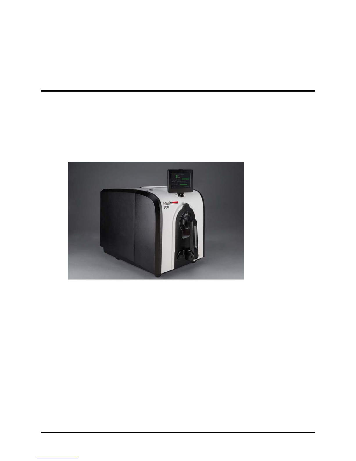
About the Datacolor 800 Spectrophotometer
The Datacolor reference-grade benchtop Datacolor 800 spectrophotometer is the newest
generation of benchtop color measuring instruments, incorporating an improved integrated
circuit technology in the instrument design. The Datacolor 800 is intended for use as a
device for measuring, specifying and evaluating color in both laboratory and production
settings, especially where precise digital color communication is required. Additional
configurations of this instrument, including the Datacolor 850, 550, and 500, are described
in the following section of this manual: Features of the Datacolor 800 and Related
Configurations.
Datacolor 800
Below is a summary of the standard and optional features included with the instruments.
Standard features include the following:
Pulsed xenon light source
Multiple aperture sizes to accommodate samples of different sizes
Automated specular port
Integrated camera and viewing display for precise sample positioning
Automated aperture detection
Automated zoom lens
Automated, adjustable ultra-violet filters for measuring fluorescent samples
Datacolor 800, 850, 500, and 550 Series User’s Guide 3
Page 6

Electrical/Environmental Requirements
Input Power
Requirements
Operating
Environment
Interfaces
Input Voltage: 100-240VAC
Number of Phases: Single
Frequency: 50/60 Hz
Power Rating: 80VA
Temperature: 5°C to 40°C
Maximum Relative Humidity: 20%-85% non-condensing
Altitude: Up to 2,000 meters
Do not store above 140F (60C)
Indoor Use
Do not crush, short circuit, mutilate, reverse polarity, disassemble, or
dispose. In fire, might cause burns or release toxic materials.
Serial: RS232
USB: 2.0
Ethernet
Datacolor 800, 850, 500, and 550 Series User’s Guide 4
Page 7
Safety Features
If the equipment is used in a manner not specified by the manufacturer, the protection
provided by the equipment may be impaired.
CAUTION
There are no user-serviceable parts for this equipment.
Light Source
Do not stare directly into the open port located in the front door panel when the
measurement is in progress.
Staring directly into the light source can result in eye discomfort similar to that of
staring at a camera flash.
Ensure that an aperture plate is installed prior to calibrating the instrument or
performing measurements.
Power
CAUTION
Disconnect power before servicing.
The power cord supplied with the unit must be used to connect to an earthed (grounded)
power supply.
Position the product such that the AC power cord that attaches to the rear of the unit is
easily accessible and can be disconnected if required.
Servicing of this instrument is to be performed only by qualified Datacolor personnel. DO
NOT remove bottom cover screws to expose internal components. The following warning is
located on the bottom cover:
HIGH VOLTAGE
DO NOT REMOVE SCREWS
ONLY TO BE OPENED BY
QUALIFIED SERVICE PERSON
Instrument Handling
This instrument is intended for use on a stable benchtop and is not meant to be a portable
instrument. In cases where it must be physically moved, two persons, each using two
hands is recommended.
Datacolor 800, 850, 500, and 550 Series User’s Guide 5
Page 8
Feature Summary
These instruments employ state-of-the-art features including the spectrometer, integrating
sphere, light source, and optics. Below is a summary of those features:
FEATURE DESCRIPTION PURPOSE/BENEFIT
Integrating sphere
Measurement
Geometry
SP2000 Spectral
Analyzer
Light source
Effective
Bandwidth
Barium coated sphere. Industry standard.
D/8º geometry, Specular
Component Included (SCI) or
Excluded (SCE).
Proprietary dual-channel
holographic grating. 256photodiode linear arrays used
for both the reference and
sample channels.
Pulsed xenon Filtered to provide D65 illumination
10nm Reliable Spectral data for
Provides for more uniform
measurement of samples with
irregular surfaces.
Dual channel design provides
continuous monitoring of sample
illumination and compensates for
changes. 256-photodiode array
enhances the precision of the
measurement.
including UV component.
determining color and color
difference.
Datacolor 800, 850, 500, and 550 Series User’s Guide 6
Page 9
Accessories
All models come with the following standard accessories:
Power cable
RS232 serial cable with connectors
USB Cable with ferrite
Black Trap
White Tile
Green Tile
White Tile Calibration data on Mini-CD or USB Memory Stick
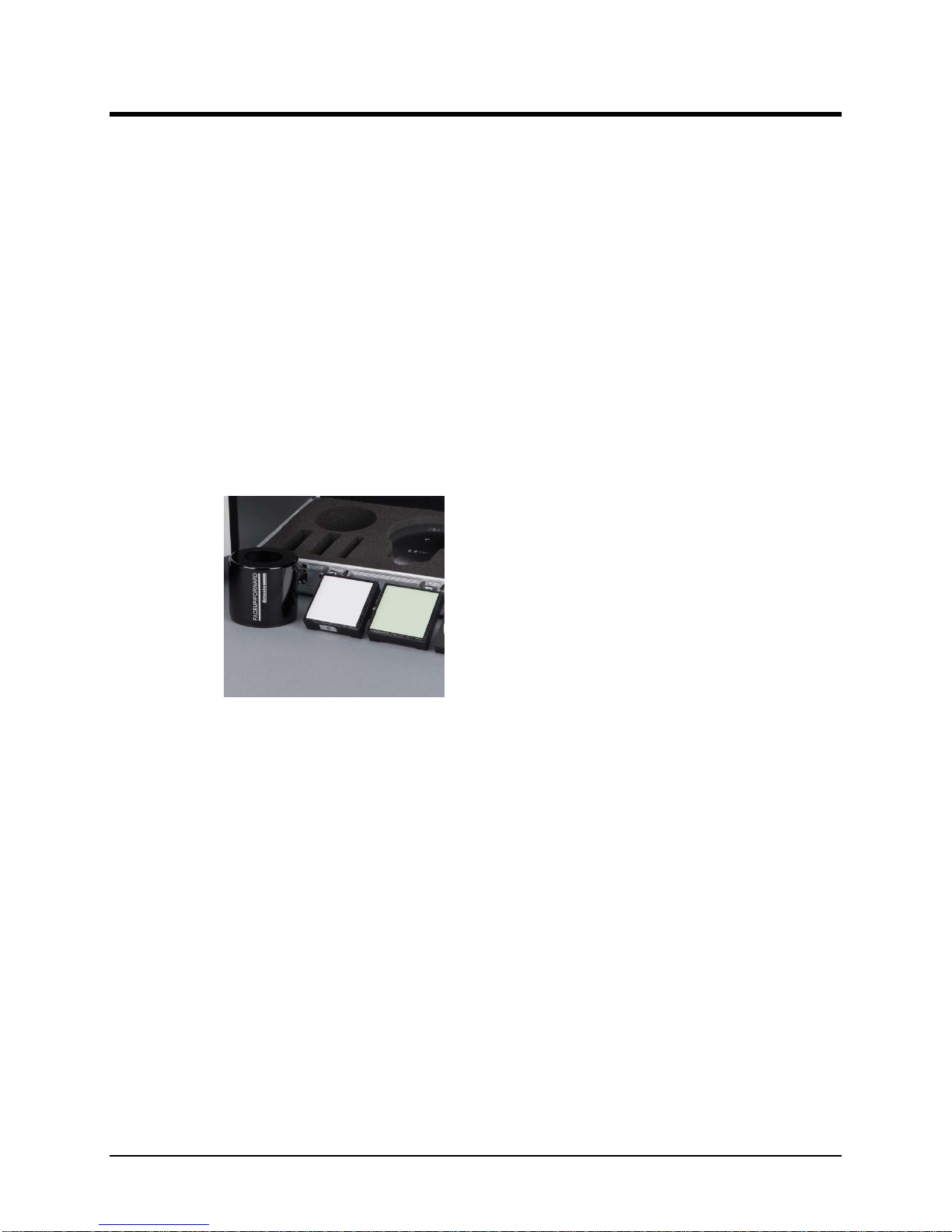
Calibration Tiles
A black trap, white tile and green tile are provided with all instruments:
The black trap and white tile are used each time the instrument is calibrated.
The green tile is used to perform an optional diagnostic test.
A CD or USB Memory Stick containing the calibration values for the white tile is
also provided.
Aperture Plates
Multiple aperture plates with openings of different sizes are included as standard
accessories with all models. The identification is engraved on each plate.
The aperture plates listed below are provided with every model (unless identified as
optional):
Large Area View (LAV)
Medium Area View (MAV) (Optional)
Small Area View (SAV)
Ultra-Small Area View (USAV)
Extra Ultra Small Area View (XUSAV) (Optional)
Datacolor 800, 850, 500, and 550 Series User’s Guide 7
Page 10
Below are aperture plate specifications:
Aperture
Identification
LAV 26mm 30mm
MAV 16mm 20mm
SAV 5mm 9mm
USAV 2.5mm 6.5mm
XUSAV 2.5mm 3.0mm
NOTE
The area illuminated is always 4mm greater than the diameter measured to reduce
translucency errors. The exception to this is the XUSAV plate.
Tips for Aperture Selection
Always use the largest possible aperture size.
The Large Area View (LAV) plate is recommended for averaging samples with
irregular surfaces and textured samples.
Small (SAV) and ultra-small (USAV) plates should only be used for
measurements of samples that do not completely cover the opening of the larger
aperture plates.
Medium (MAV) with barium coating must be used for transmission
measurements.
Sample Area
Measured
Sample Area
Illuminated
Datacolor 800, 850, 500, and 550 Series User’s Guide 8
Page 11
Transmittance Options
The Datacolor 850/550 includes an option to measure the transmission properties of
transparent and translucent samples. The 850/550 can measure the “regular” transmittance
of transparent solid and liquid samples, as well as the “total” and “diffuse” transmittance of
translucent samples. The Datacolor 850/550 can also be used to perform the following
evaluations:
Haze evaluations, in compliance with ASTM D1003 Standard Test Method for
Haze and Luminous Transmittance of Transparent Plastics, for materials that
exhibit slight light scattering.
APHA evaluation, which measure the yellowness of liquids.
The transmission compartment of the Datacolor 850/550 is large enough to allow the
operator to easily insert and remove samples. It has been fitted with a spill tray in the event
of minor spillage of liquid samples.
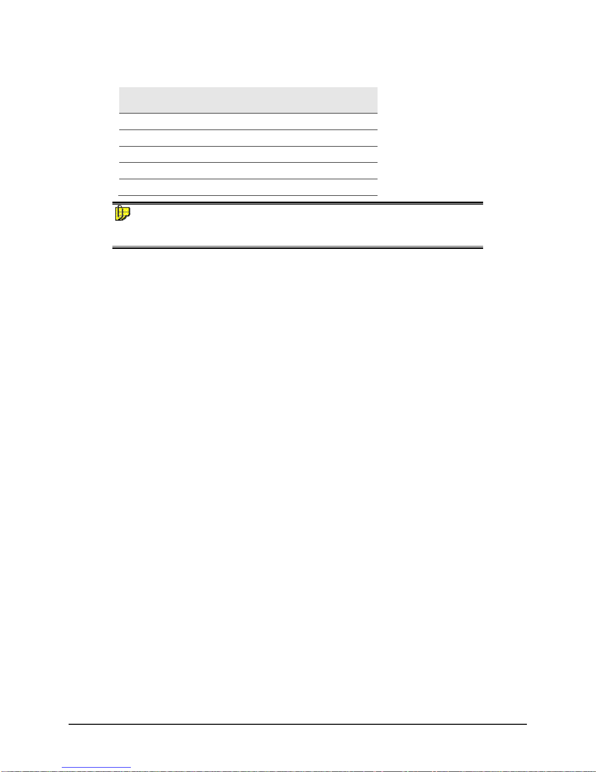
Accessing the Transmission Compartment
There are side-latch buttons on each side of the Datacolor 850/550 case that are used to
open the transmission case:
Button
Depress these buttons, and slide the case toward the back of the instrument, to open the
transmission compartment. Reverse the process to close the transmission compartment. The
case will lock in the Open and Closed positions:
Datacolor 800, 850, 500, and 550 Series User’s Guide 9
Page 12
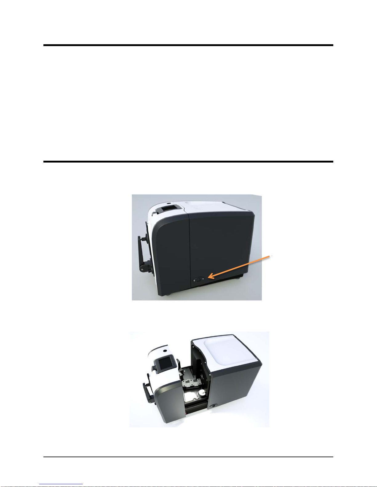
Transmission Accessories
The following accessories must be installed in order to perform transmission measurements:
Solid Sample
Holder
Cuvette Holder
(Liquid Samples)
Transmission Sample Holder
Base.
Used to mount the
Transmission Sample Holders.
Installed at the factory.
Transmission Sample Holders.
Installed as required by user.
Spill Tray.
Installed at factory to catch minor
spills.
NOTE
The cuvette holder is designed to hold an optical glass cuvette 50mm X 10mm (Datacolor
Part No. 2950-0004).
Datacolor 800, 850, 500, and 550 Series User’s Guide 10
Page 13
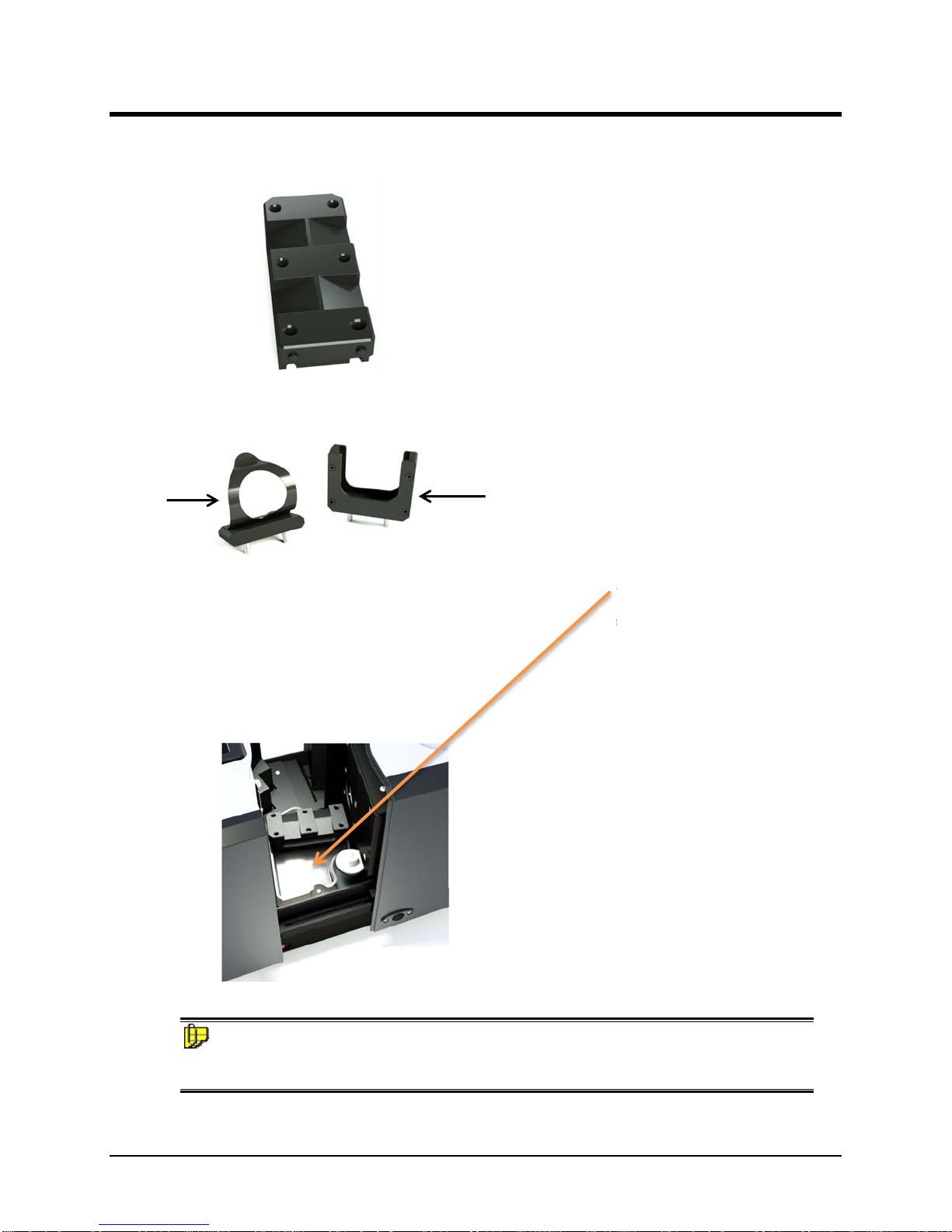
Transmission Sample Holders
Two sample holders are provided to accommodate various types of transparent samples.
Solid Sample Holder
Two thumb screws provide the ability to adapt
the holder to samples of varying thicknesses.
Cuvette and Cuvette Holder (Liquid Samples)
This holder is designed for use with a 50mm X
10mm optical glass cuvette.
These sample holders are mounted onto the transmission sample holder base via two dowels
protruding from the bottom of the holders.
NOTES
Loosen the thumbscrews on the solid sample holder to aid in the installation of the sample
holder. Make sure the sphere opening/lens opening is completely covered by the sample you
are going to measure. No special tools are required to install the sample holders.
Datacolor 800, 850, 500, and 550 Series User’s Guide 11
Dowel Pins
Page 14
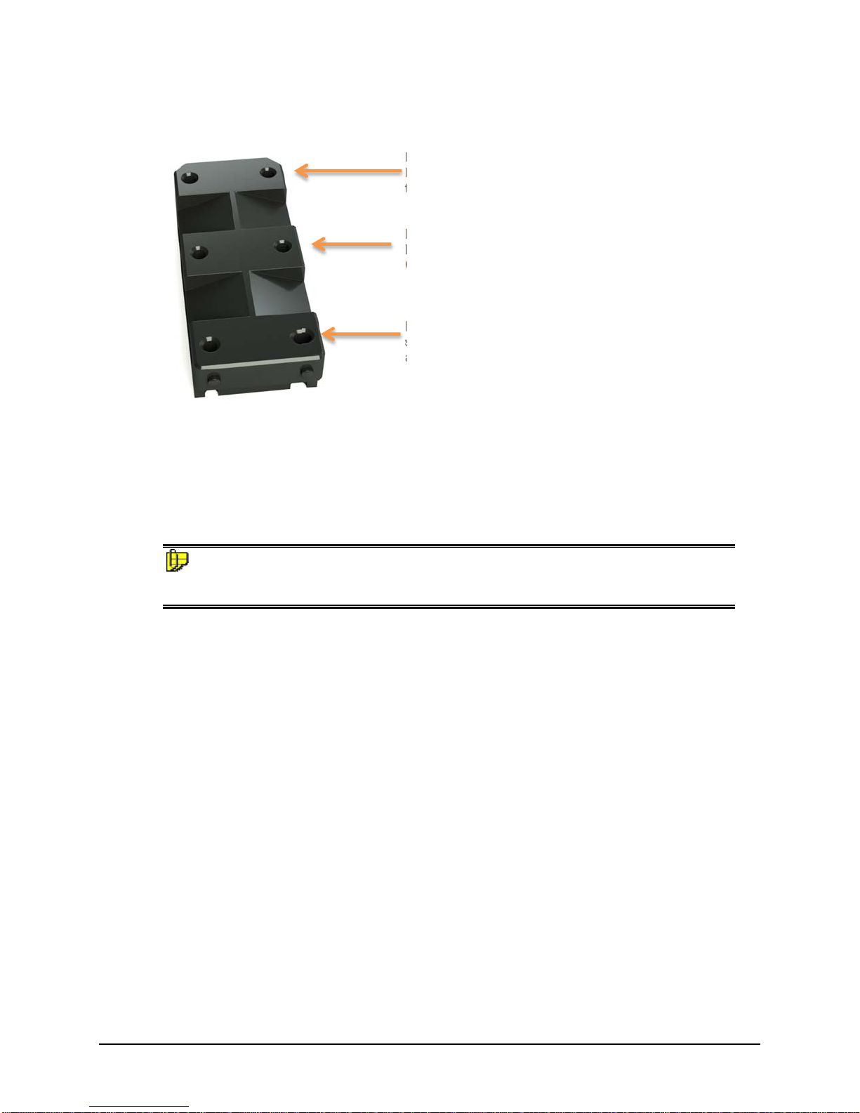
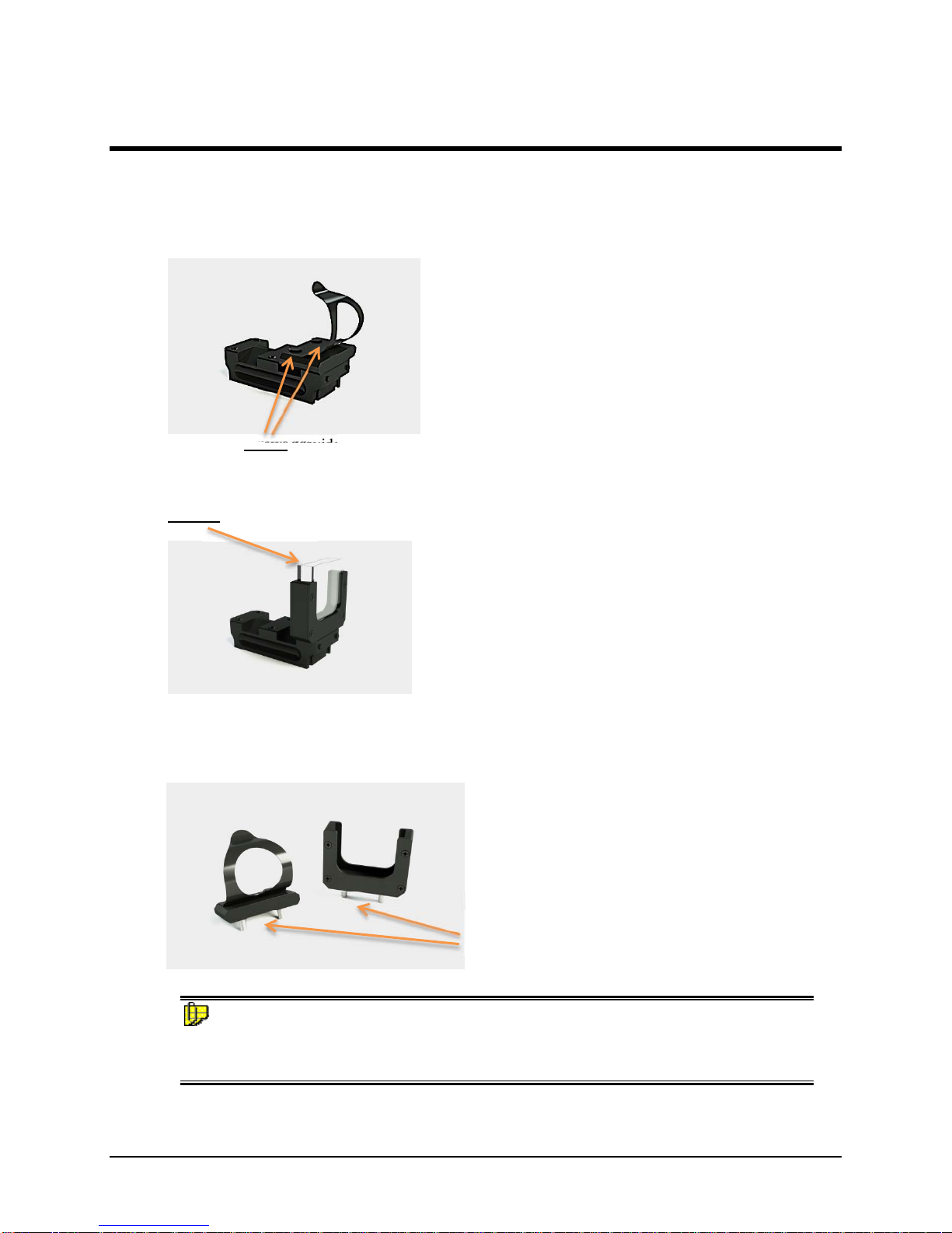
Transmission Sample Holder Base
Position 3. Places the sample close to the lens.
It is used to measure regular transmission of
transparent materials.
Position 2. This is provided for ease of
handling when measuring regular transmission.
Can only be used with the cuvette holder.
Position 1. Places the sample close to the
sphere. Used to measure translucent samples
and to make haze measurements.
The base is installed at the factory and includes three positions to locate the sample between
the sphere and the lens.
The location of the sample holder along the base depends upon the type of material being
measured.
NOTES
The base should remain in the transmission compartment, but the sample holders (Solid or
Cuvette) must be removed for Reflectance calibration and measurement.
Datacolor 800, 850, 500, and 550 Series User’s Guide 12
Page 15
Cable Installation
Overview
You must install a power cable and an interface cable (either a USB, serial or an Ethernet
cable) to connect the instrument to a computer.
NOTE
Do not connect all interface cables to the unit. You have a choice of using an Ethernet
cable, serial cable or a USB cable.
The connections for the cables are found on the back of the instrument.
WARNING
Read the "Electrical and Environmental Requirements” section BEFORE connecting your
instrument.
Power Cable
A power cable is provided with the instrument.
NOTE
The power cord supplied with the unit must be used to connect to an earthed (grounded)
power supply.
Power is supplied to the back of the unit via a 3-prong male connector.
Plug the female end of the power cord into the power receptacle on the rear panel of the
instrument. Insert the plug into a standard AC outlet.
Serial Cable Installation
You can connect the instrument to the computer using either a serial cable, Ethernet cable,
or a USB cable. Select one of them. This section provides instructions for using the serial
cable.
NOTE
Do not connect all interface cables to the unit at the same time.
Datacolor 800, 850, 500, and 550 Series User’s Guide 13
Page 16

The serial cable is shown below:
1. Connect the 9-pin male connector on the serial cable to the RS-232C female
connector on the rear panel of the instrument.
2. Connect the female connector on the serial cable to a serial communications port
on the back of the computer.
3. If there is more than one serial port on the computer, make a note of the port
being used. You may need to enter this information into the program.
4. Tighten each connection securely to ensure proper signal.
See the Appendix for a description of the RS-232C connector pin assignments.
Datacolor 800, 850, 500, and 550 Series User’s Guide 14
Page 17

USB Cable Installation
Instruments manufactured by Datacolor can be connected to a USB port on a desktop
system. See Appendix, System Requirements for US B Connection before you attempt to
connect to a USB port.
You can connect the instrument to the computer using either a serial cable, Ethernet cable,
or a USB cable. Select one of them. This section provides instructions for using the USB
cable.
NOTES
Do not connect all interface cables to the unit at the same time.
If you use the USB cable, you may need to install additional software to activate the USB
port. See also Driver Installation below for instructions to add this software.
Before You Begin
Close all programs currently running on the system.
You will need the accessories listed below to complete the installation:
USB cable (provided by Datacolor).
USB Memory Stick or CD included with the instrument (this is required only
when installing new instruments)
Three steps must be completed to enable the USB port for use with the instrument:
Install the USB cable (as shown below).
Identify the COM port assignment for the USB port. This is accessed through the
Device Manager on the Control Panel included with the Windows operating
system.
Change the COM port assignment in the Datacolor applications software.
Cable Installation
The USB cable provided with the system is shown below:
One end of the cable connects to a USB port on the instrument. The other connects to a
USB port on the computer.
Connect the USB cable to the instrument and to the USB port on the back of the
To Instrument
To Computer
computer.
Datacolor 800, 850, 500, and 550 Series User’s Guide 15
Page 18

Driver Installation
All current Datacolor software ships with the necessary drivers for the Datacolor 800. If you
are using Third party software with the Datacolor 800, please contact Datacolor Support via
our website at:
http://industrial.datacolor.com/industrial-support/
Viewing/Changing System Port Assignment
As part of the USB driver installation, a COM port number is assigned to the USB port. The
default selection is the next available COM port. Depending on the application you are
running, you may need to know this port assignment to configure the Datacolor applications
program(s) to recognize the USB port.
NOTES
Some Datacolor programs automatically configure the USB port assignment. Others
require that you manually assign the port number. Refer to the program User’s Guide for
information to assign/edit the instrument port number.
Datacolor 800, 850, 500, and 550 Series User’s Guide 16
Page 19

Ethernet Cable Installation
Instruments manufactured by Datacolor can now be connected to an Ethernet port on a
desktop system. See Appendix, Ethernet Connection Considerations, before you attempt
to connect to an Ethernet port.
You can connect the instrument to the computer using either a serial cable, Ethernet cable,
or a USB cable. Select one of them. This section provides instructions for using the
Ethernet cable.
NOTE
Do not connect all interface cables to the unit at the same time.
An Ethernet cable is shown below:
1. Connect either end of the Ethernet cable to the connector on the rear panel of
the instrument.
2. Connect the other end of the Ethernet cable to an Ethernet LAN port.
3. Observe the LCD Status Display and note the IP address of the instrument. You
will need to enter this information into the appropriate software (e.g. TOOLS).
Refer to the program User’s Guide for information regarding where to enter the
IP address.
See the Appendix for additional Ethernet Connection Considerations.
Datacolor 800, 850, 500, and 550 Series User’s Guide 17
Page 20

Controls and Indicators
Controls and Indicators Panel
On all benchtop models, an LCD Status Display is located on the instrument. It identifies
the current instrument settings being used.
The LCD Status Display will include information regarding:
Set measurement conditions (aperture, specular port, UV)
Calibration time remaining
IP Address (if connected to Ethernet)
Serial number of the White Tile
Date and level of last service
Serial number of the instrument
Installed firmware version
NOTE
Depending on the model, the LCD Status Display can be raised and rotated to the left
or right. Do not rotate the LCD more than 45 degrees to the left or right while the
LCD is raised.
Datacolor 800, 850, 500, and 550 Series User’s Guide 18
Page 21

Powering Up
NOTE
The power cord supplied with the unit must be used.
Use this simple procedure to start using your instrument:
1. Verify all cable connections. The AC power cord should be plugged into an
outlet. A communications cable (serial, Ethernet, or USB) should be attached to
the instrument and host computer or LAN connection as applicable.
2. Turn on the computer.
3. Turn on the instrument power switch. This is located on the side of your
instrument.
When power is applied, all mechanisms are automatically reset.
The LCD will display updates as the instrument starts up, until the final LCD
Status Display is shown.
NOTE
If the instrument power is not turned on before a Datacolor program is
launched, you may receive an error message.
4. Depending on the model you are using, the LCD Display may include the status
of the following mechanisms:
Aperture plate/zoom lens position
UV filter status
Specular port status
When the LCD Status Display is shown, your instrument is ready to use.
5. Launch a Datacolor program on your computer.
6. Prepare to calibrate the instrument. You will need the black trap, the white
calibration tile and the green diagnostic tile.
Datacolor 800, 850, 500, and 550 Series User’s Guide 19
Page 22

N O T E S
Datacolor 800, 850, 500, and 550 Series User’s Guide 20
Page 23

Instrument Calibration
Overview
The instrument must be calibrated regularly to ensure that the measurements are accurate.
This section provides instructions for performing both reflectance and transmittance
calibrations.
NOTE
We recommend that you calibrate the instrument every 8 hours. Please refer to your
software documentation for specific calibration instructions.
Installing Calibration Data
If this is a new instrument, you will not need to install the calibration data. The White
Calibration Tile data is preloaded at the factory. However, Datacolor recommends that
White Calibration Tiles be replaced annually. If you need to replace your White Calibration
Tile, please contact your local Datacolor office. Upon receipt of a new tile, calibration data
can be found on the USB Memory Stick or CD included with the tile. Install the data directly
on the instrument by inserting a USB Memory Stick containing the WHITESE.DAT and
WHITESI.DAT files into the USB port at the rear of the instrument. A menu of options will
appear on the instrument’s LCD Status Display. Below is an example of the installation
procedure.
NOTE
The Remote Measure Button serves multiple purposes. In this scenario, one short click will
allow you to cycle through the menu options, while pressing and holding for approximately
one second will select a menu option.
1. Upon inserting the USB Memory Stick into the instrument, while the LCD Status
Display is shown, you will see the screen change to one that is similar to the
screen below:
Navigation between the menu options is performed with short clicks of the
Remote Measure button.
Activating a selected menu option is performed with by pressing and holding the
Remote Measure button for approximately one second.
Datacolor 800, 850, 500, and 550 Series User’s Guide 21
Page 24

(Activating the “Exit USB Mode” option will quit the USB mode and returns you to
the LCD Status Display.)
2. Updating the White Tile is initiated by selecting (short clicks) and activating (long
press) the “Update White Tile” option.
This option will overwrite the older files on the instrument with the new
WHITESE.DAT and WHITESI.DAT files on the USB stick, corresponding to the
new White Calibration Tile. The instrument will automatically be restarted after
the update. The LCD Status Display will reflect the serial number of the new tile.
Datacolor 800, 850, 500, and 550 Series User’s Guide 22
Page 25

Reflectance Calibration
The instrument should be calibrated every 8 hours to compensate for changes in the
environment. A black trap, white tile and green tile are provided with all instruments to
complete the calibration:
The black trap and white tile are used each time the instrument is calibrated. The green tile
is used to perform an optional diagnostic test.
Reflectance Calibration Procedure
The software prompts for calibration vary from one program to another. All of the
procedures include two measurements:
The black trap
The white tile
Before you begin, verify that the aperture plate at the port matches the aperture selection in
the program you are running.
1. Access the calibration procedure in the program you are running.
2. When you are prompted by the program, place the black trap at the instrument
port.
3. When you are prompted by the program, place the white tile at the instrument
port.
4. The program may prompt you for a diagnostic tile. If prompted, place the green
tile at the instrument port, and start the measurement.
5. After these measurements are completed, the program will display a message
that the calibration is successful. You can now start measuring samples.
The Datacolor User’s Guide for the program you are running (e.g., Datacolor TO OLS, etc.)
provides step-by-step instructions regarding the (instrument) software setup and calibration
procedure.
NOTES
If sequential total transmittance and reflectance measurements are going to be made using
the Datacolor 850/550, the instrument should be calibrated for both transmittance and
reflectance conditions. Transmittance measurements are made using the barium-coated
MAV aperture plate.
Datacolor 800, 850, 500, and 550 Series User’s Guide 23
Page 26

UV Filter Calibration
The procedure for calibrating the adjustable UV filter is performed in reflectance mode, and
requires the use of a UV calibration standard obtainable from a number of standardization
organizations. Datacolor provides a fluorescent white tile (Fluorescent Reference
Standard) that may be used as a reference standard after the instrument has been
calibrated for UV using an official UV calibration standard. An applicable whiteness value
can only be assigned to the Datacolor Fluorescent Reference Standard after the instrument
has been calibrated for UV using an official UV calibration standard. This procedure
requires the selection of specific software options. See also the Datacolor TOOLS User’s
Guide, which contains step-by-step instructions to calibrate the adjustable UV filter.
NOTES
This calibration procedure is critical to the accurate measurement, either reflectance or
transmittance, of fluorescent samples.
If you are sharing either reflectance or transmittance data for fluorescent samples, the
adjustable UV filter in each of the instruments must be calibrated regularly.
Datacolor 800, 850, 500, and 550 Series User’s Guide 24
Page 27

Transmittance Calibration
The following accessories are used to calibrate the instrument for transmittance:
Barium-coated MAV Aperture Plate
Calibration Procedure
Before you begin, you should verify the current aperture selection. The setting must be
Medium Area View (MAV) and the barium-coated MAV plate (for transmittance measurements
only) should be placed at the instrument port.
White Spectralon® Plaque.
Placed at the
sample port for calibration.
port for many transmission measurements. Consult the
standard procedure (ASTM, ISO, etc.) you are following to
determine if this sample should be placed at the port.
Black Card. Used to “block”
the lens during calibration (“zero” calibration).
In addition, it is placed at the
NOTE
Transmittance calibration and measurements must be made using the barium-coated Medium
Area View (MAV) aperture plate. This special aperture plate is not used for reflectance
measurements.
To calibrate the instrument for transmittance measurements, do the following:
1. Place the barium-coated MAV aperture plate at the port.
2. Open the transmission compartment and make sure the optical path between the
sphere and the lens is clear.
3. Access the calibration procedure in the program you are running. You may need
to change the selections for the aperture plate, and measurement mode
(transmission). See also the User’s Guide for the program you are running for detailed
instructions to access the instrument setup and calibration options.
Datacolor 800, 850, 500, and 550 Series User’s Guide 25
Page 28

4. When you are prompted by the program, block the lens using the black card:
5. When the measurement is completed, remove the black card from the transmission
compartment.
6. Place the white Spectralon® plaque at the sample port, and make the next
measurement.
NOTES
The white Spectralon® plaque remains at the port for “Regular” and “Total” Transmittance
measurements, and is replaced with the black trap for “Diffuse” Transmittance measurements.
See also
Transmittance Measurements
.
Datacolor 800, 850, 500, and 550 Series User’s Guide 26
Page 29

Sample Presentation and
Measurement
Sample Presentation and Measurement Overview
You must pay close attention to the positioning of the sample to insure an accurate
measurement. When positioned correctly, the sample rests between the sample holder
and the front panel door. The sample must completely cover the aperture opening.
Reflectance Measurements
1. Grasp the sample holder and pull forward.
2. Position the sample, then carefully bring arm back up to normal operating
position.
WARNING
Do not allow sample arm to spring back. Also, the sample arm attaches
to the instrument via two captive fasteners that can be hand tightened.
Before first use, ensure that the sample arm is firmly attached.
Sample Viewing Port
When measuring small samples, you may need to check that the sample is properly
positioned at the port. To verify that the correct area of the sample is being measured:
1. Place the sample at the port. Grasp the black tab above the aperture plate.
2. Pull top of door down to its full horizontal position.
3. The backside of this door reveals the area of the sample covering the port
4. Push the door back to its normal position.
For the Datacolor 800V (vertical mount), the cylindrical, spring-loaded
sample holder can be depressed to position your sample. You can
return the cylinder to its normal position with a quarter turn of the
cylinder.
opening. If necessary, adjust the placement of the sample to target the portion of
the sample to be measured.
Datacolor 800, 850, 500, and 550 Series User’s Guide 27
Page 30

Sample Viewing Display
When measuring samples on the Datacolor 800, 800V, and 850, the status display also
serves as a display for sample placement. Toggle to the sample camera view on the LCD
by pressing and holding the Remote Measure Button for approximately one second.
Remote Measure Button
The button at the top of the instrument is used to start a measurement from the instrument,
rather than from the program. Depending upon your instrument model, it can also be used
to toggle to and from a display of video from an internal camera used for sample
placement. Toggling the display between the LCD Status Display and the camera video
can be performed by pressing and holding the button down for approximately one second.
Datacolor 800, 850, 500, and 550 Series User’s Guide 28
Page 31

Transmittance Measurements
Three techniques are used to measure the transmittance of samples: “regular”
transmittance, “total” transmittance and “diffuse” transmittance.
Regular Transmittance
When working with samples that are completely transparent (such as dyes in solution or
transparent plastics) you are measuring “regular” transmittance. These samples need to be
positioned close to the lens opening at the back of the transmission compartment using
either the cuvette holder or solid sample holder as appropriate:
Regular Transmittance
Datacolor 800, 850, 500, and 550 Series User’s Guide 29
Page 32

Total, Diffuse, and Haze Transmittance
When measuring the transmittance of translucent samples that contain particles, such as
engineered resins or opal glass, you are measuring either “total” or “diffuse” transmittance.
The samples should be positioned at the front of the transmission compartment, close to
the sphere opening.
“Total” transmittance measurements are made with the white Spectralon® plaque in place
at the front aperture plate and the sample placed against the sphere opening.
“Diffuse” transmittance measurements are made with the black trap in place at the front
aperture plate and the sample placed against the sphere opening.
Haze assessments are made using two measurements, one with the white Spectralon®
plaque, the other with the black trap installed at the front aperture plate. For both
measurements, the sample must be placed against the sphere opening.
NOTES
Use the solid sample holder to place the solid sample flush against the sphere opening. In
order to ensure the best measurement, there must be no gap between the sample and the
sphere opening in “Total”, “Diffuse”, or Haze measurements.
Datacolor 800, 850, 500, and 550 Series User’s Guide 30
Page 33

Total Transmittance
Diffuse
Transmittance
Consult with your Applications Specialist regarding the measurement technique you should
use for specific evaluations.
Datacolor 800, 850, 500, and 550 Series User’s Guide 31
Page 34

N O T E S
Datacolor 800, 850, 500, and 550 Series User’s Guide 32
Page 35

Maintenance
About Instrument Maintenance
The certificate of performance supplied with this instrument is valid for one (1) year under
the following conditions:
It is used in an environment suitable for the instrument type.
It is handled and used with care.
Datacolor strongly recommends that the instrument be serviced once/year by an authorized
service engineer.
Datacolor offers a variety of maintenance and certification services to match your needs.
Please contact your local Datacolor office for more information.
The sections that follow provide detailed instructions for maintaining the instrument and
calibration tiles. These instructions and tips will help to insure that the instrument continues
to perform properly over its life.
CAUTION
There are no user-serviceable parts for this equipment.
Exterior Surface Cleaning
The white, exterior surface of the instrument can be cleaned with an isopropyl alcohol wipe.
For more persistent stains, acetone can also be applied.
Sphere Cleaning
The measurement port should be examined visually for the presence of dust, sample
particles, fibers, and excessive yellowing due to environmental influences. This inspection
should be performed frequently, especially if you measure loose materials.
Loose materials in the sphere should be removed by a Datacolor-certified technician.
Datacolor 800, 850, 500, and 550 Series User’s Guide 33
Page 36

Tile Handling and Cleaning
Handling Tiles
Handle calibration tiles with extreme care. Do not drop them, or scratch the
glazed surface.
Always use the edges to grasp the tile.
Cleaning Tiles
The calibration tiles should be cleaned before each use. Wipe each tile clean
with a soft, lint-free cloth.
A detergent, free of optical brighteners, fluorescent materials or photoactive dyes
should be use as needed to clear any oils, fingerprints or other deposits. Liquid
dish detergent is a suitable detergent. The detergent/water solution should be
prepared as follows: 1 part detergent : 250 parts water. Use a few drops of the
detergent solution to moisten a soft, lint-free cloth, and gently wipe the tile
surface. Rinse the detergent from the tile by wiping it with a cloth, moistened
with clean water.
NEVER use abrasive cleansers, razor blades or other metal objects to remove
dirt or foreign substances from the calibration tiles. This will damage the surface.
NEVER immerse the tiles in water.
Tiles that have scratches, chips, abrasions or cracks must be replaced. Signs of
wear and tear on the tile surface will affect the accuracy of the calibration.
Tile Storage
Large temperature variations will affect the accuracy of the calibration, requiring
more frequent calibration. The calibration tiles should be stored in an
environment that simulates the temperature of the samples to be measured.
Prolonged exposure to sunlight or other sources of ultra-violet radiation will
cause the color of the tiles to change. The tiles should always be stored in a
protective case or container away from direct sunlight and environmental
contaminants.
Datacolor 800, 850, 500, and 550 Series User’s Guide 34
Page 37

Cleaning the Black Trap
The black trap should be kept dust-free. Dust accumulating in the black trap should be
blown out with compressed air.
Cleaning the Spectralon® Plaque
This is the white plaque used for transmission calibration and measurement. It is an optical
standard and should be handled in the same way as other optical standards. All efforts
should be made to prevent contaminants from contacting the surface of the plaque. We
recommend that you wear gloves when handling this plaque.
WARNING
Do NOT use Freon to air brush this plaque.
Cleaning Instructions
If the tile is lightly soiled, it may be air brushed with a jet of clean dry air or nitrogen. For
heavier soil, the material can be cleaned using the following procedure:
1. Sand the surface under running water with a 220 – 240 grit waterproof emery cloth, until the
surface is totally hydrophobic (water beads and runs off immediately).
2. Blow dry with clean air or nitrogen, or allow the material to air dry.
Datacolor 800, 850, 500, and 550 Series User’s Guide 35
Page 38

Handling and Cleaning the Cuvette
This is used for the measurement (Transmittance) of liquid samples. All efforts should be
made to prevent scratches and contaminants from contacting the surface of the cuvette.
We recommend that you wear gloves when handling the cuvette and grasp it from the
opaque sides only.
WARNING
Handle with care by grasping the opaque sides only. Do not scratch the surface with
abrasive cleaning materials. Only use materials appropriate for the cleaning of optical
glass.
The cuvette is made of optical glass. It is recommended that standard methods
applicable to the cleaning of optical glass cuvettes be used as required between the
measurements of different samples.
Datacolor 800, 850, 500, and 550 Series User’s Guide 36
Page 39

Instrument Status
The LCD Status Display includes a color coded (green, yellow, red) Instrument Status bar.
Normally, this bar will be green in color and the Status Codes field will be blank. Certain
conditions, including the ones listed below, may cause the Instrument Status bar to be
yellow or red in color. Corresponding Status Codes will also be displayed. Should these
conditions occur, please contact your local Datacolor office for more information and
guidance regarding next steps.
Item Condition CodeandColor
AgeofWhiteTile
(Replacementrecommended
yearly)
ControlMeasurements
(TakenduringCalibration)
Timesincelast
Maintenanceand
Certification
10‐12monthsold 00111;Yellow
>12monthsold 00121;Red
dE>=.5foragivensetof
00211;Yellow
measurementconditions.
>12months 00311;Yellow
Datacolor 800, 850, 500, and 550 Series User’s Guide 37
Page 40

Exporting Diagnostic Data
Diagnostic data is stored on the instrument. Your local Datacolor office may ask for this
data in order to remotely service your instrument. This data can be retrieved via a USB
Memory Stick.
1. Upon inserting a USB Memory Stick into the instrument, you will see a screen
similar to the one below:
The above option menu is displayed only when inserting the USB stick while on
the LCD Status Display.
Navigation between the menu options is performed with short clicks of the
Remote Measure button.
Activating the currently selected menu option is performed with by pressing and
holding the Remote Measure button for approximately one second.
(Activating the “Exit USB Mode” option will quit the USB mode and displays the
LCD Status Display.
2. Exporting diagnostic data is initiated by selecting (short clicks) and activating
(long press) the “Export Data” option
Datacolor 800, 850, 500, and 550 Series User’s Guide 38
Page 41

3. When the export is complete, the following will be indicated:
4. The data will be stored in a folder named with the following pattern: “Backup”<InstrumentModel>-<InstrumentSerialNumber>-<CurrentDateTime>
Updating Firmware
The instrument’s firmware can also be updated via a USB Memory Stick. Please contact
your local Datacolor office before attempting to update the instrument’s firmware.
Datacolor 800, 850, 500, and 550 Series User’s Guide 39
Page 42

N O T E S
Datacolor 800, 850, 500, and 550 Series User’s Guide 40
Page 43

Appendix
Datacolor 800 Instrument Specifications
Specifications are subject to change without notice.
ITEM DESCRIPTION
Instrument Type
Measuring Geometry
Illumination Source
Sphere Diameter
Specular Port
Spectral Analyzer
Wavelength Range
Photometric Range
Black Trap
Aperture Configuration
Input Power
Requirements
Operating
Environment
Interface
LCD
Dual beam integrating sphere with xenon flash lamp.
Diffuse illumination, 8º viewing in conformance with CIE
publication No. 15.2 Colorimetry.
Pulsed xenon, filtered to approximate D65.
152 mm / 6.0 inches
Automated specular included or specular excluded
Proprietary SP 2000 analyzer with dual 256-diode array and highresolution holographic grating.
360 – 700nm
0 to 200%
High performance
Large Area View. 30mm illuminated/ 26mm viewed
Medium Area View. 20mm illuminated/ 16mm viewed
Small Area View. 9mm illuminated/ 5mm viewed
Ultra-Small Area View. 6.5mm illuminated/ 2.5mm viewed
X-Ultra Small Area View*. 3mm illuminated/ 2.5mm viewed
Input Voltage: 100-240VAC
Number of Phases: Single
Frequency: 50/60 Hz
Power Rating: 80VA
Temperature: 5°C to 40°C
Recommended Temperature: 23°C +/- 2°C
Maximum Relative Humidity: 20%-85% non-condensing
Recommended Relative Humidity: 50% +/-15% non-condensing
Altitude: Up to 2,000 meters
Do not store above 140F (60C)
Indoor Use
Do not crush, short circuit, mutilate, reverse polarity, disassemble,
or dispose. In fire, might cause burns or release toxic materials.
Serial: RS232
USB: 2.0
Ethernet
3.5" RGB Color Display Module
Datacolor 800, 850, 500, and 550 Series User’s Guide 41
Max Resolution 320 x 240
Maximum Pixel Clock 28 MHz
Page 44

Power Consumption 150mA @ 3.3 V
Operating Temp. -20°C to +70°C
Dimensions 82 x 77 x 11.55 mm
Instrument Dimensions**
* Sample translucency may affect inter-lens agreement
** Dimensions shown are for horizontal mount instruments.
Size: L 16.4” (41.66 cm) front
to back
L18.5” (46.99 cm) sample arm
to back
H 13.2” x W 12.3” (33.53 cm x
31.24cm)
Weight: 37.5 lbs (17.01kg)
Datacolor 800, 850, 500, and 550 Series User’s Guide 42
Page 45

Features of the Datacolor 800 and Related Configurations
FEATURE Datacolor
800
Reporting Interval
Effective Bandwidth
20 Read
Repeatability on
White Tile Using
Two Flashes
(CIELAB)
Inter-instrument
Agreement—
Reflectance
Measurements*
(CIEL*a*b*)
Lens
Aperture Plates
Aperture Detection
Automated,
adjustable UV
Calibration
UV Cutoff Filters
Remote
Measurement
Button
Camera
Vertical Mount
Transmittance
Inter-instrument
agreement – regular
transmittance at 550
nm
Inter-instrument
agreement –
transmission haze
measurements
10nm 10nm 10nm 10nm 10nm 10nm
10nm 10nm 10nm 10nm 10nm 10nm
0.01 dE
(max)
0.15
(max)*
0.08
(avg)*
4 position
autozoom
3
standard
LAV
SAV
USAV
2 optional
MAV
XUSAV
Yes Yes Yes Yes Yes Yes
Yes Yes Yes No Yes Yes
400 nm
420 nm
460nm
Yes Yes Yes Yes Yes Yes
Yes Yes Yes No No No
No Yes No No No No
No No Yes No No Yes
— — ±0.20% at
— — ±0.15% at
Datacolor
800V
0.01 dE
(max)
0.15
(max)*
0.08
(avg)*
4 position
autozoom
3
standard
LAV
SAV
USAV
2 optional
MAV
XUSAV
400 nm
420 nm
460nm
Datacolor
850
0.01 dE
(max)
0.15 (max)*
0.08 (avg)*
4 position
auto-zoom
4 standard
LAV
SAV
USAV
MAV
(Barium
Coated)
2 optional
MAV
XUSAV
400 nm
420 nm
460nm
85% T
±0.10% at
32% T
10% TH
Datacolor
500
0.03 dE
(max)
0.30
(max)*
0.15
(avg)*
4 position
autozoom
3
standard
LAV
SAV
USAV
2 optional
MAV
XUSAV
NA 400 nm
— — ±0.40% at
— — ±0.30% at
Datacolor
500UV
0.03 dE
(max)
0.30
(max)*
0.15
(avg)*
4 position
autozoom
3
standard
LAV
SAV
USAV
2 optional
MAV
XUSAV
420 nm
460nm
Datacolor
550
0.03 dE
(max)
0.30 (max)*
0.15 (avg)*
4 position
auto-zoom
4 standard
LAV
SAV
USAV
MAV
(Barium
Coated)
2 optional
MAV
XUSAV
400 nm
420 nm
460nm
85% T
±0.20% at
32% T
10% TH
Datacolor 800, 850, 500, and 550 Series User’s Guide 43
Page 46

Transmission
— — 22 mm — — 22 mm
aperture size
* Measurements made at 23º C +/- 1º C.
Datacolor 800, 850, 500, and 550 Series User’s Guide 44
Page 47

Miscellaneous Technical Information
System Requirements for USB Connection
Below are the software and firmware versions required to successfully connect a Datacolor
instrument to a USB port.
Operating Systems
USB Firmware
Windows 7 or higher
2.0 or higher
Ethernet Connection Considerations
The instrument connects to an Ethernet port via a standard Cat 5 cable. Because the
distance from the instrument to the closest available LAN connection point varies per
installation, a cable is not provided. Both the instrument and the associated computer must
be on the same Local Area Network (LAN) and configured to be on the same Subnet (e.g.
255.255.255.0). This is not a point to point connection between the instrument and the
computer.
NOTES
The Instrument relies upon a DHCP Server to obtain an IP address and does not have a Host
Name.
RS-232C Connection (Communication Settings)
Parameter Value
Baud Rate 115200
Data Bits 8
Stop Bits 1
Parity N
RS-232C Connector Pin Assignments
Pin # Purpose Direction
2 Transmit data Out (to host)
3 Receive data In (from host)
7 Signal ground
CAUTION
(1) DO NOT WIRE to pins other than 2, 3, and 7.
(2) For all unused inputs, the default is active high.
Datacolor 800, 850, 500, and 550 Series User’s Guide 45
Page 48

Datacolor Global Support
A complete User’s Guide is provided with this product. However there are also resources
regarding color education on the Datacolor website, including contact information for local
Datacolor offices.
http://industrial.datacolor.com/support/contact-us-2/
Datacolor 800, 850, 500, and 550 Series User’s Guide 46
 Loading...