

Page 1

SP55 Printer Guide
554733-001
August 2004
Page 2

Information resources for the SP55 Printer
Installation To install the printer:
To install one printer on a PC using a USB cable,
see the Installation Map, packed at the top of the
printer carton.
For detailed installation information or for special
situations (such as network inst al l a ti on ), see
e-Guide/SP Series/SP_Info_Central.chm on the
driver CD-ROM.
Message Help If you see a message, click Help on the message
Really! Help topics are short and to the point.
box.
Printer Guide The Printer Guide (this document) contains
operating information for the printer and driver.
SP Info Central
and e-Guide
FAQs
Dealer
Customer Care
For in-depth information about using the printer or
driver, click the SP Info Central icon on the desktop.
(Insert the CD-ROM and choose User Information
to install SP Series Info Central if the icon is not on
the desktop.)
Service and Support FAQs at www.datacard.com provide answers to questions about the SP55 printer.
For help with questions not addressed by other SP55 information, contact your dealer.
Contact the Datacard Customer Care Center at 1.800.328.3996 (U.S. & Canada) or 1.952.988.2316
(worldwide).
Page 3

Contents
About the printer . . . . . . . . . . . . . . . . . . . . .1
Loading cards . . . . . . . . . . . . . . . . . . . . . . . 5
Loading print ribbon . . . . . . . . . . . . . . . . . . . 7
Check the PC connection . . . . . . . . . . . . . . . . 9
Status light . . . . . . . . . . . . . . . . . . . . . . . . 11
Opening Properties or Printing Preferences . . 13
Open the Printer Toolbox . . . . . . . . . . . . . . 15
Cleaning the printer . . . . . . . . . . . . . . . . . . 17
Printer supplies . . . . . . . . . . . . . . . . . . . . . 19
Getting the most out of your printer . . . . . . . 21
Troubleshooting . . . . . . . . . . . . . . . . . . . . . 23
Site requirements . . . . . . . . . . . . . . . . . . . . 25
Legal Notices (FCC) . . . . . . . . . . . . . . . . . . 27
539335-001 Rev. C Page iii
Page 4

About the printer
The outside of the printer
Duplex Module: Optional module at the back of
the printer.
Printer Cover.
Latch: Lift the latch to open the printer cover.
Input Hopper: Open the cover to load blank cards.
Output Hopper: Remove completed cards.
Ready button: Push to pause or resume
the printer.
The status light helps you
understand printer operation.
See “Status light” on page 11 for details.
Page 1
Page 5

Ports are located on the left side of the printer.
USB Data Port: Connect the data cable to the printer.
ALL printers have this port.
Manual Advance Knob: Use to move a card in the
printer or to turn rollers.
Power Receptacle: Plug in the power supply to power
on the printer.
Cable Guides: Hold the data cable securely.
Security lock receptacle: Connect the optional
security lock to the opening under the ledge of the
printer (not visible in this drawing).
Optional Smart Card USB Port: See “Features and
options” on page 4.
Optional Smart Card Serial Port: See “Features and
options” on page 4.
Tip: Lift the latch to open the printer and see inside.
Page 2
Page 6

The inside of the printer
Cover Arm: Holds the cover and printhead cartridge in place.
Printhead Cartridge: Applies the image to the card. The label
includes ”YMC” for color or “K” for monochrome printheads.
Print Ribbon Cartridge (shown with color print ribbon).
Printer Label: Includes the serial number and model
information (located on the left side of the printer and not
visible in this drawing).
Cleaning roller (not visible in this drawing): Removes dust
and debris from cards.
Page 3
Page 7

Features and options
Features and options are identified on the printer label.
• Printers with “U” printing can print one color (monochrome)
only. “C” printing is full-color or monochrome printing.
• All SP55 printers have a USB connection.
• SP55 printers can include a duplex module.
•A magnetic stripe module can be a three-track (IAT) or
single-track (NTT) module. It is visible inside the printer.
• SP55 Printers can have an 100-card (H1) or 200-card (H2)
Input Hopper. The Input Hopper can have a lock (K1).
• An optional sm ar t ca r d mod u l e ca n ha ve :
• Contact coupler (SC1x0 on the label): Visible inside the
printer. Includes a USB port on the printer.
• Contactless (RF) coupler (SC20x): Includes a serial or
USB port.
• Combination smart card coupler (SC3xx): Contact and
contactless couplers. Visible inside the printer, includes
USB or serial port. See SP Series Info Central for codes.
• Contact station (SC400): Visible inside the printer.
Includes a serial port.
Page 4
Page 8

Loading cards
1 Open the input hopper cover.
2 Remove cards from the original package.
Tips: Handling cards
• Do not touch the surface of cards before printing
them. (Oils on hands will reduce printing quality.)
• Handle cards by the edges or wear gloves.
• Cards can stick
together: Slide or
fan cards to
separate the edges.
• Orient all cards the same way.
Page 5
Page 9

3 Place the cards in the input hopper.
The diagram shows the typical locations for the
magnetic stripe and smart card chip.
4 Push the input hopper cover closed until it
latches.
See SP Series Info Central for current information
about cards to use in the printer.
Magnetic stripe
Smart card chip
Page 6
Page 10
Loading print ribbon
1 Open the printer.
2 Remove the ribbon cartridge.
3 Remove both used ribbon spools from the cartridge
(if present).
Tips: Handling print ribbon
• Keep unused ribbon in the original package.
• Don’t place ribbon on a dusty or dirty surface–dirt
could damage the printhead.
4 Run a cleaning card and replace the cleaning sleeve
at the same time that you load a new print ribbon.
“Cleaning the printer” on page 17 for the steps to
See
follow.
Page 7
Page 11

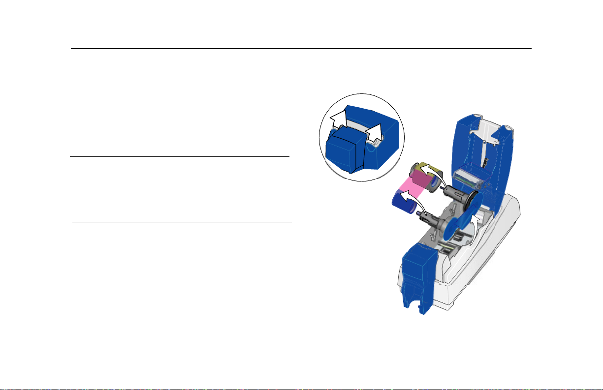
5 Load the new roll of print ribbon on the cartridge.
— Put the full spool of ribbon on the supply spindle of the
ribbon cartridge. Push until the spool clicks onto the
spindle.
— Put the empty take-up spool on the spindle with the
solid black gear. Push until the spool clicks onto the
spindle.
6 Replace the loaded ribbon cartridge in the printer.
— Make sure both spindles rest in the black supports on
the left side of the printer.
— Make sure the ribbon cartridge handle rests in the
supports on the right side of the printer.
— Make sure to install the full, new spool toward the input
hopper of the printer.
7 Close the printer cover. Press down firmly to latch it.
Page 8
Page 12
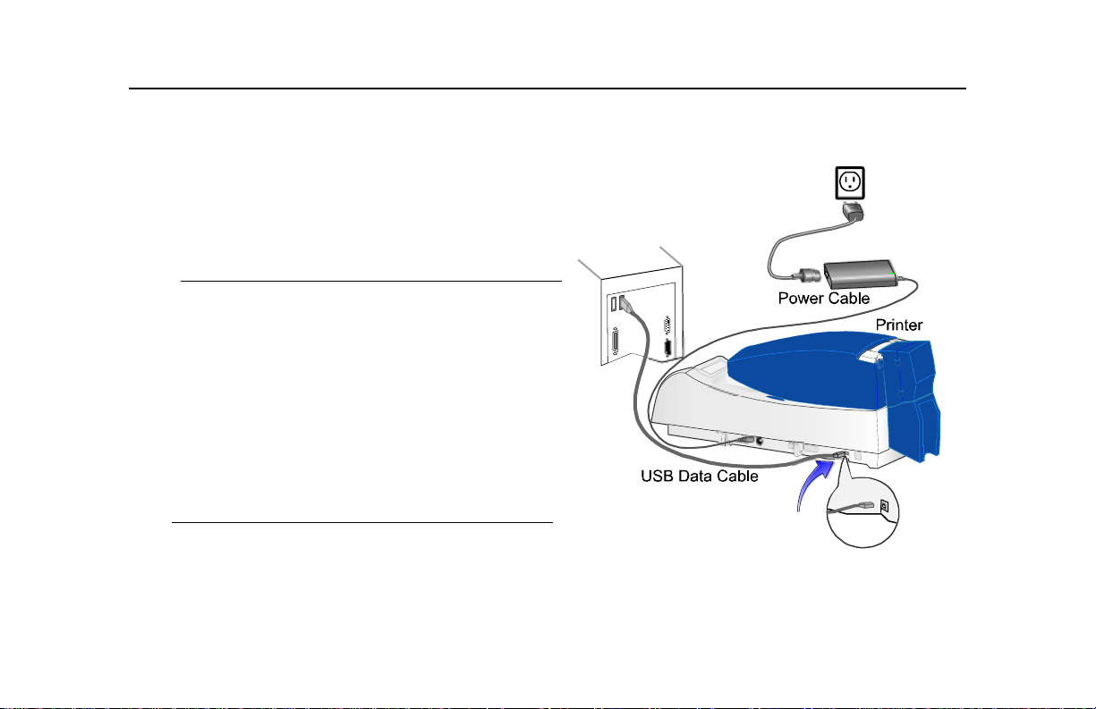
Check the PC connection
The printer and PC are connected when the printer is
set up. Before beginning card processing, make sure the
connection is complete.
Page 9
The USB data cable should be connected to a USB port
on the PC and to the USB data port on the printer.
The printer can be connected in these other ways:
Through a direct network connection, where the
printer is connected to a network (using a print
server) and the PC is connected to the same
network.
As a shared printer, where the printer is connected
to another PC on the network and the user’s PC is
connected to the network.
See SP Info Central for more information about
connecting the printer.
PC
Page 13
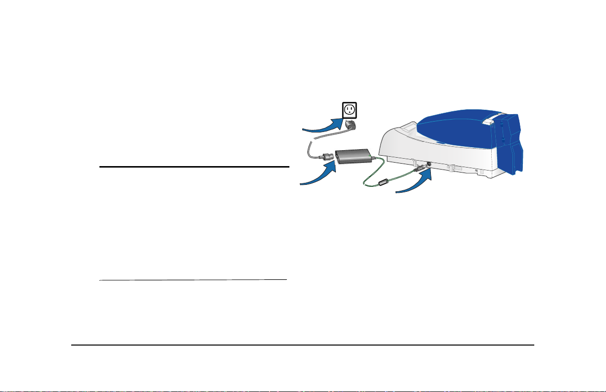
Power on the printer
Plug in the printer to power it on.
The printer does not have a power switch.
1
Make sure the power supply cord connects to
the printer power receptacle (1).
2 Connect the power cord to the power supply (2).
3 Connect the power cord to the power outlet (3).
4 The printer powers on and initializes.
Tips for printer power
Wait while the printer initializes.
The printer Status Light displays steady green
when the printer is ready to print cards. See
“Status light” on page 11 for details.
Follow the guidelines for your organization about
when to power the printer on and off.
3
2
1
Page 10
Page 14

Status light
The front of the printer has a light that provides information about the current state of the printer.
At startup, the status light displays steady amber for several seconds, a red-amber-green sequence, and then
blinking green for several seconds. When the printer is ready to print, the status light is steady green.
Status Light Description Meaning
Red-Amber-Green The printer is starting. The light displays colors while
the printer initializes.
Steady Green The printer is ready and waiting to print cards.
Blinking Green The printer is busy, such as when printing cards or
initializing.
Steady Amber The printer is paused (without an error) or is initializing.
Page 11
Page 15

Status Light Description Meaning
Blinking Amber The printer has an error. Check the following:
• See the PC for a message.
• If you used the Power-on/Ready sequence to
• If you changed the printer name, power the PC
Steady Red The printer has a condition that requires service or the
printer did not power-on correctly. To attempt to correct
the condition, power the printer off and on before
calling for service.
Off The printer power is off.
print a test card, check the printer for problems.
off and on.
Page 12
Page 16

Opening Properties or Printing Preferences
Begin with the printer connected to the PC and
powered on so values are saved correctly.
1 Choose Start from the Windows task bar.
2 Choose Settings and then Printers (and Faxes).
The Printers (and Faxes) window opens.
3 Click once on the SmartDriver printer icon to
select it.
• The driver must be installed for the printer icon
to be present.
• SmartDriver is the default name of the printer.
The name of your printer might be different.
4 From the menu bar, choose File and then one of
the following:
• For Windows Me or 98, choose Properties.
• For Windows 2000 or XP, choose Printing
Preferences, and then click the Advanced
button.
Properties dialog box for Windows 98 SE and
Windows Me
Page 13
Page 17

5
The dialog box opens.
6 V iew settings or change settings.
• Make sure that driver settings match printer
features and supplies used.
• The Print Ribbon Type setting is read from
the printer and cannot be changed (for most
connection types).
• If you change the card design, review and
update all settings for the new card design.
• Use the default settings of “Spool printing
so program finishes printing faster.” and
“Enable bi-directional support.”
7 Choose OK to save and close or choose
Cancel to close without saving changes.
See SP Series Info Central for detailed setup
information, including information about settings for
card features.
Printing Preferences dialog box for Windows
2000 and Windows XP
Page 14
Page 18

Open the Printer Toolbox
The Printer Toolbox icon is located in the lower right
corner of the Windows desktop. The icon shows the
status of communication between the printer and driver.
See SP Series Info Central for details about the icon.
By default, the Printer Tool box dialog box is displayed. If
it is not, do one of the following to display it:
• Open the Properties or Printing Preferences
dialog, and click Printer Toolbox.
• Double-click the icon.
Use the Printer Toolbox to:
• Run a cleaning card.
• Change color settings.
• Print a sample card or magnetic stripe card.
• View the status of commu nication between th e printer
and PC.
• Suspend communication when not printing a card.
• Change edge to edge settings.
• Use Advanced Setup to change printing intensity.
Page 15
Page 19

The Printer Toolbox displays:
• The current state of communication between the
driver and printer.
• Message text, if there are any messages.
• The current port mode, which can be USB, Shared
Mode, or Directly Networked.
• The printer type.
• The driver and printer firmware version numbers.
Communication automatically resumes when you print a
card, or when you open the Properties or Printing
Preferences dialog box.
Buttons on the Printer To olbox are grayed out when a
card is ready to print or is printing, when there is a
message, or when the printer is powered off. Wait until
printing is done before printing a sample card, running a
cleaning card, or using advanced setup. Some buttons
do not apply to this printer and are always gray.
See SP Series Info Central for more information about
the Printer Toolbox.
Page 16
Page 20

Cleaning the printer
Run a cleaning card and change the cleaning sleeve when
changing the print ribbon. Make sure that all cards sent to the
printer have completed printing before cleaning.
1 Open the printer cover and remove the ribbon cartridge.
2 Remove the replaceable cleaning roller.
3 Open the input hopper cover (1).
4 Remove unprinted cards from the input hopper (2).
5 Open the Printer Toolbox (if needed, see page 15).
6 Click the Clean Printer button. A prompt to insert the
cleaning card appears.
7 Open the cleaning card package and remove the
cleaning card.
Page 17
Clean Printer
button
8 Insert the cleaning card into the input hopper (3), just past
the roller.
9 Click OK on the message box. The printer moves the card
through the printer several times and ejects the card. Wait
a few minutes to allow the rollers to dry.
1
3
2
Page 21

10
Slide the used cleaning sleeve off the spindle.
11 Discard the used cleaning card and used sleeve.
12 Place a new cleaning sleeve on the spindle (1).
13 Remove the protective cover from the sleeve (2).
14 Insert the replaceable cleaning roller (with a new cleaning
sleeve) into the printer (3).
15 Replace the ribbon cartridge, close the printer cover, load
cards, and resume printing.
Cleaning tips
Use the cleaning card as soon as you open the package. The
cleaning solution on the card evaporates after a few minutes.
Some card features, such as signature panels and magnetic
stripes, can require more frequent cleaning of the printer.
Clean printer rollers regularly, such as every time you change
the ribbon.
If you use StickICards™, use a cleaning card after every 100
cards. The printer might also need additional cleaning.
See SP Series Info Central for more cleaning information.
1
2
3
Page 18
Page 22

Printer supplies
Datacard-certified ribbon kits and cleaning supplies are available for the printer. Ribbon kits contain a roll of print
ribbon, a cleaning card, and a replaceable cleaning sleeve. Datacard recommends that you run a cleaning card
and replace the cleaning sleeve each time you change the print ribbon.
Color print ribbon
Color print ribbon for the printer is available as follows:
• YMCKT Color Ribbon Kit, part number 552854-204, prints up to 250 images
• YMCKT Color Ribbon Kit, part number 552854-504, prints up to 500 images
• YMCKT-KT Color Ribbon Kit, part number 552854-506, prints up to 300 images (for duplex printing)
Color print ribbons are designed for full-color card printing. The ribbons use the following color panels: Y=yellow,
M=magenta, and C=cyan/blue, a K=black, and a T=topcoat (clear). Datacard color print ribbon for SP Series
printers uses Advanced Imaging Technology™ for high quality printing.
Monochrome and Topcoat ribbon
Ribbon with alternating Black (K) and Topcoat (T) panels is available as part of the KT Ribbon Kit, part number
552854-509, which prints up to 1000 images.
Monochrome print ribbon
Several colors of monochrome (single-color) print ribbon are available for the SP Series printer. A roll of ribbon
prints 1500 or more images. The Ribbon Saver feature is enabled by Datacard-certified monochrome ribbons.
Page 19
Page 23

Ribbon Saver increases the number of cards printed with each roll of ribbon. Available monochrome colors
include:
Color Part number Color Part Number
Black 552954-501 Silver 552954-507
Black HQ
Dark Blue 552954-502 Metallic Silver 552954-607
White 552954-503 Metallic Gold 552954-608
Red 552954-504 Scratch-off 552954-513
Green 552954-506 Metallic Holo Fleck 552954-609
*. For use only in SP Series color card printers
*
552954-601 Gold 552954-508
Cleaning supplies
In addition to the cleaning supplies included in the ribbon kit, Datacard recommends that you order additional
cleaning supplies to have on hand to address unusual situations.
• A package of 5 replaceable cleaning sleeves is available. The part number is 549716-002.
• A package of 10 cleaning cards is available. The part number is 552141-002.
See SP Series Info Central for complete information about supplies and replacement parts for SP Series printers.
Page 20
Page 24

Getting the most out of your printer
To get the best quality cards and to maintain printer performance, follow these tips
for success:
• Use the best quality cards available with a smooth, glossy PVC surface and
print them only once. Make sure options, such as a Mylar® signature panel or a
magnetic stripe, are high quality.
• Match the card design and the supplies you use to obtain the results you want.
— Edge to edge printing requires high-quality cards and can require fine-tuning
the printer (using the SmartDriver) and the card design (using the card
creation application).
— Avoid placing an image or important data on the other side of the card from a
magnetic stripe, smart card chip, or signature panel.
— Locate bar codes at least 0.25 inches from other printing and from the edge
of the card. Make sure the color used to print the bar code works in your bar
code readers.
— Do not print closer than 0.1 inch from a signature panel, magnetic stripe, or
smart card chip.
— Do not apply topcoat over a magnetic stripe, signature panel, or smart card
chip.
• Follow instructions carefully when replacing supplies, correcting problems,
cleaning the printer, and replacing parts.
Page 21
Page 25

• Use cables that meet specifications and connect them correctly.
• Keep cards and Datacard-certified supplies on hand and store them safely.
• Keep the printer clean and keep the area around the printer clean.
See SP Series Info Central for detailed information about:
• Setting up the printer for the card design
• Making cards
• Changing printer settings
• Troubleshooting
• Supplies and parts, and specifications for them
Page 22
Page 26

T roubleshooting
What is the problem? Try this:
Page 23
1 A message appeared on the PC or
LCD panel.
2 The printed cards do not look the
way that I want them to.
3 Cards jam often.
4 The ribbon has broken.
• Click the Help button on the message box to see possible
causes and the solution for each cause. See the “Related
Topics” to fix the problem.
• If you moved the ribbon while the printer was powered off, print
another card. If the problem persists, see the SP Series Info
Central for detailed information about solving card appearance
problems.
• The brand of cards might be dirty, heavily powdered, or bowed
(curved). Consider buying a different brand of cards or clean the
printer more often to use the cards.
• The printer rollers might be dirty. See “Cleaning the printer” on
page 17 for steps to clean the printer rollers.
• Trim the end of the broken ribbon evenly. If ribbon on the takeup spool is not wound firmly or is uneven, remove it. Tap e the
end of the ribbon onto the same take-up spool, making the
edges of the ribbon and spool even.
• If the ribbon breaks repeatedly, settings might not be correct for
the card design and ribbon. See Setup in SP Series Info Central.
Page 27

What is the problem? Try this:
5 The printer does not respond when
I print a card or when I click
“Resume” on the Printer Toolbox.
6 The printer cover will not close.
• Make sure the printer is plugged in. See “Power on the printer”
on page 10.
• Make sure the printer is connected to the computer. “Check the
PC connection” on page 9.
• If the Status Light on the printer is blinking amber (yellow), press
the Ready button.
• Power off the printer and power it on to see if communication
resumes.
• See SP Series Info Central for more detailed communication
troubleshooting information.
• Push down firmly on the front edge of the cover to latch it.
• Make sure no extra items are inside the printer.
• Make sure the print ribbon cartridge is installed correctly. See
“Loading print ribbon” on page 7.
• If you installed or bumped the printhead cartridge, make sure it
is installed correctly. See SP Series Info Central.
Page 24
Page 28
Site requirements
Operating environment
• Relative humidity: 20% to 80% non-condensing
• Temperature: 60° F to 95° F (15° C to 35° C)
Electrical requirements
• The external power supply is rated at 100-240 VAC, 50-60 Hz,
1.8 amp. (It adjusts to any power within this range.)
• Single phase, 3-wire, grounded receptacle only.
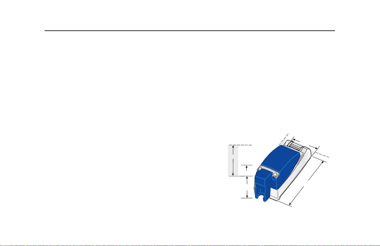
Physical requirements
• The printer weighs less than 11.5 pounds (5.3 kg). The weight
depends on the supplies and options installed.
• Printer dimensions are 21.5 inches (546 mm) long and 7.8
inches (198 mm) wide. The 100-card input hopper is 9.5 inches
(241 mm) high and the 200-card hopper is 11.9 inches (302 mm)
high.
• The clearance required 1 inch (25 mm) at the back, 2 inches (5
cm) on the left side, and 10.5 inches (267 mm) above the printer
latch to open the cover.
Do not use the printer in a dirty environment. Do not use the printer
in a closed compartment. Do not block air flow around the printer.
10.5” (for cove r )
11.9”
9.5”
Page 25
2”
7.8”
1”
21.5”
Page 29

Legal Notices (FCC)
Please note and heed the WARNING and CAUTION labels that have been placed on the equipment for your
safety. Please do not attempt to operate or repair this equipment without adequate training.
Liability statement
This Datacard® product has been built to the high standards of DataCard® Corporation. See SP Series Info
Central for the statement of liability.
Regulatory compliance
This Datacard® product conforms to FCC and regulatory requirements as specified in North America, Europe, and
Asia. See SP Series Info Central for detailed regulatory compliance information.
Trademark acknowle dgm e nts
Trademark, service mark, and copyright acknowledgments are listed in SP Series Info Central.
Proprietary Notice
All drawings and information herein are the property of DataCard® Corporation.
© 2003-2004 DataCard® Corporation. All rights reserved.
Page 30

11111 Bren Road West
Minnetonka, MN 55343-9015
952.933.1223
952.933.7971 FAX
www.datacard.com
Datacard is a registered trademark of DataCard Corporation.
August 2004 554773-001 Rev. C
Dealer information:
 Loading...