

Page 1
User's Manual
WR-8826-FX / WR-8826-TFX / WR-6412-FX / WR-6415-FX
WR-320-FX / WR-322S-FX / WR-121S-FX / WR-151S-FX
Antes de utilizar el equipo, lea la sección
“Precauciones de seguridad” de este manual.
Conserve este manual para futuras consultas.
Before operating the device, please read the
“Safety precautions” section of this manual.
Retain this manual for future reference.
Page 2
CONTENTS
SAFETY PRECAUTIONS
WARRANTY
DECLARATION OF CONFORMITY
INTRODUCTION
CONFIGURATIONS
4 x WR-8826 (625W @ 8 Ohms)
8 x WR-8826 (1150W @ 4 Ohms)
16 x WR-8826 (2100W @ 2 Ohms)
4 x WR-6412 o WR-6415 (1150W @ 4 Ohms)
8 x WR-6412 o WR-6415 (2100W @ 2 Ohms)
16 x WR-6412 o WR-6415 (3700W @ 2 Ohms)
LINE DRAWINGS
SPECIFICATIONS
INSTALLATION
ACCESSORIES
TROUBLESHOOTING
ANNEX : Table for cable selection
3
4
5
6 - 8
9 - 11
12
13
14 - 15
16 - 23
24
25
Manual del Usuario / WR series / User’s Manual
Page 3

Cajas acústicas pasivas / Passive loudspeaker enclosures
Precauciones de Seguridad
Safety Precautions
El signo de exclamación dentro de un triángulo indica la
existencia de importantes instrucciones de operación y
mantenimiento en la documentación que acompaña al producto.
Conserve y lea todas estas instrucciones.
Siga las advertencias.
El doble cuadrado indica equipo de Clase II. The double square indicates Class II device.
Las especificaciones se encuentran en la etiqueta de la parte
posterior del producto.
No exponga este equipo a la lluvia o humedad sin el protector
de lluvia recomendado. No use este aparato cerca del agua
(piscinas y fuentes, por ejemplo). No exponga el equipo a
salpicaduras sin el protector de lluvia recomendado, ni coloque
sobre él objetos que contengan líquidos, tales como vasos y
botellas.
Equipo IP-56 (IP-54 en los modelos WR-6412) según la norma
IEC 60529: 1989 + M1 @ 1999 con un ángulo horizontal mínimo
de -2º.
Este símbolo indica que el presente producto no puede ser
tratado como residuo doméstico normal, sino que debe
entregarse en el correspondiente punto de recogida de equipos
eléctricos y electrónicos.
Equipo diseñado para funcionar entre -25ºC y 45ºC con una
humedad relativa máxima del 95%.
El cableado exterior conectado al equipo requiere de su
instalación por una persona instruida o el uso de cables flexibles
ya preparados.
The exclamation point inside an equilateral triangle is intended to
alert the users to the presence of important operating and
mainten an ce (servi ci ng ) ins tr uc tions i n the l it er ature
accompanying the product.
Heed all warnings. Follow all instructions.
Keep these instructions.
The specifications can be found on the rear label of the product.
Do not expose this device to rain or moisture without the rain
protector supplied. Do not use this apparatus near water (for
example, swimming pools and fountains). Do not place any
objects containing liquids, such as bottles or glasses, on the top
of the unit. Do not splash liquids on the unit without the rain
protector supplied.
IP-56 equipment (IP-54 for WR-6412 models) according IEC
60529: 1989 + M1 @ 1999. Minimum horizontal angle -2º.
This symbol on the product indicates that this product should
not be treated as household waste. Instead it shall be handed
over to the appicable collection point for the recycling of
electrical and electronic equipment.
Working temperature ranges from -25ºC to 45ºC with a relative
humidity of 95%.
The outer wiring connected to the device requires installation by
an instructed person or the use of a flexible cable already
prepared.
El equipo cuenta con dos conectores de entrada en paralelo
para facilitar la conexión de varias cajas en paralelo.
No emplace altavoces en proximidad a equipos sensibles a
campos magnéticos, tales como monitores de televisión o
material magnético de almacenamiento de datos.
El colgado del equipo sólo debe realizarse utilizando los herrajes
de colgado recomendados y por personal cualificado.
No existen partes ajustables por el usuario en el interior de este
equipo. Cualquier operación de mantenimiento o reparación
debe ser realizada por personal cualificado. Es necesario el
servicio técnico cuando el equipo se haya dañado de alguna
forma, como que haya caído líquido o algún objeto en el interior
del aparato, haya sido expuesto a lluvia o humedad, no funcione
correctamente, haya recibido un golpe o su cable de red esté
dañado.
Limpie con un paño seco. No use limpiadores con disolventes. Clean only with a dry cloth. Do not use any solvent based
Note that the two Speakon input connectors are wired in parallel
to provide easy parallel connection of several enclosures.
Do not place loudspeakers in proximity to devices sensitive to
magnetic fields such as television monitors or data storage
magnetic material.
The appliance should be flown only from the rigging points and
by qualified personnel.
No user serviceable parts inside. Refer all servicing to qualified
service personnel. Servicing is required when the apparatus has
been damaged in any way, such as power-supply cord or plug is
damaged, liquid has been spilled or objects have fallen into the
apparatus, the apparatus has been exposed to rain or moisture,
does not operate normally or has been dropped.
cleaners.
Manual del Usuario / WR series / User’s Manual
3
Page 4

GARANTÍA
Todos nuestros productos están garantizados por un periodo de 24
meses desde la fecha de compra.
Las garantías sólo serán válidas si son por un defecto de
fabricación y en ningún caso por un uso incorrecto del producto.
Las reparaciones en garantía pueden ser realizadas,
exclusivamente, por el fabricante o el servicio de asistencia técnica
autorizado.
Otros cargos como portes y seguros, son a cargo del comprador
en todos los casos.
Para solicitar reparación en garantía es imprescindible que el
producto no haya sido previamente manipulado e incluir una
fotocopia de la factura de compra.
WARRANTY
All our products are warrantied against any manufacturing defect
for a period of 2 years from date of purchase.
The warranty excludes damage from incorrect use of the product.
All warranty repairs must be exclusively undertaken by the factory
or any of its authorised service centers.
To claim a warranty repair, do not open or intend to repair the
product.
Return the damaged unit, at shippers risk and freight prepaid, to
the nearest service center with a copy of the purchase invoice.
4
Manual del Usuario / WR series / User’s Manual
Page 5

DECLARACIÓN DE CONFORMIDAD
DECLARATION OF CONFORMITY
DAS Audio Group, S.L.
C/ Islas Baleares, 24 - 46988 - Pol. Fuente del Jarro - Valencia. España
(Spain).
Declara que
WR-8826-FX / WR-8826-TFX / WR-6412-FX / WR-6415-FX / WR-320-FX / WR-322S-FX /
WR-121S-FX / WR-151S-FX:
Declares that
WR-8826-FX / WR-8826-TFX / WR-6412-FX / WR-6415-FX / WR-320-FX / WR-322S-FX /
WR-121S-FX / WR-151S-FX:
Cumple con los objetivos esenciales de las Directivas:
Abide by essential objectives relating Directives:
l De Baja Tensión / Low Voltage 2014/35/UE
l RoHS 2011/65/UE
l RAEE (WEEE) 2012/19/UE
Y son conformes a las siguientes Normas Armonizadas Europeas:
In accordance with Harmonized European Norms:
l EN 60065:2014.- Audio, video and similar electronic apparatus. Safety
requirements.
l EN 50581:2012.- Technical documentation for the assessment of
electrical and electronic products with respect to the restriction of
hazardous substances.
Manual del Usuario / WR series / User’s Manual
5
Page 6

INTRODUCTION
The WR FX series is a series of products aimed at the outdoor installation market (Weather Resistant).
Features
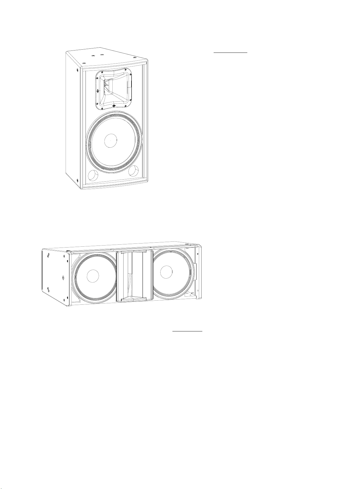
WR-8826FX / WR-8826TFX
– 2-way system for outdoor installation
– FX finish (Fiberglass) for direct exposure
– ISO-flex interior coating
– 2 x 6B, 6" loudspeaker,
– 1" annular diaphragm compression driver
– Stainless threaded fixing points for wall mounts
– Version with line transformer is the WR-8826FXT
The WR-8826FX employs twin 6B woofers for low
frequency reproduction. A 1” annular diaphragm
compression driver provides brilliant highs. The birch
plywood cabinet construction offers an ultra-compact
design which is available in black or white. This enclosure
is IP-56 according IEC 60529.
The WR-8826FX has been designed for the outdoor
installation market. The WR “FX” finish protects the
cabinets outdoors thanks to a fiberglass exterior and ISOflex interior protection augmenting their weather resistance
when used in direct exposure situations. Stainless steel
threaded rigging points and optional mounting hardware
are available. Version with 75 W/100 V factory installed
line transformer is available, WR-8826FXT.
WR-8826-FX / WR-8826-TFX
WR-6412FX
– 2-way system for outdoor installation
– FX finish (Fiberglass) for direct exposure
– ISO-flex interior coating
– 1 x 12AV, 12" loudspeaker
– M-75 compression driver with 3" annular diaphragm
– Rotatable 60º x 40º horn design
– Stainless threaded fixing points for wall mounts
The WR-6412FX employs a single 12AV woofer for low
frequency reproduction. An M-75 compression driver with
3" titanium diaphragm attached to a 60º x 40º rotatable
horn provides exceptional high frequency reproduction.
The birch plywood cabinet construction offers an ultracompact design which is available in black or white. This
enclosure is IP-54 according IEC 60529.
The WR-6412FX has been designed for the outdoor
installation market. The WR “FX” finish protects the
cabinets outdoors thanks to a fiberglass exterior and ISOflex interior protection augmenting their weather resistance
when used in direct exposure situations. Stainless steel
threaded rigging points and optional mounting hardware
are available.
WR-6412-FX
6
Manual del Usuario / WR series / User’s Manual
Page 7
WR-6415-FX
WR-6415FX
– 2-way system for outdoor installation
– FX finish (Fiberglass) for direct exposure
– ISO-flex interior coating
– 1 x 15AV, 15" loudspeaker
– M-75 compression driver with 3" annular diaphragm
– Rotatable 60º x 40º horn design
– Stainless threaded fixing points for wall mounts
The WR-6415FX employs a single 15AV woofer for low
frequency reproduction. An M-75 compression driver with
3 titanium diaphragm attached to a 60º x 40º rotatable
horn provides exceptional high frequency reproduction.
The birch plywood cabinet construction offers an ultracompact design which is available in black or white. This
enclosure is IP-56 according IEC 60529.
The WR-6415FX has been designed for the outdoor
installation market. The WR “FX” finish protects the
cabinets outdoors thanks to a fiberglass exterior and ISOflex interior protection augmenting their weather resistance
when used in direct exposure situations. Stainless steel
threaded rigging points and optional mounting hardware
are available.
WR-320-FX
WR-320FX
– Installation Line Array
– 2 x 10Mi low frequency loudspeakers, 2.5" VCD
– 1 x M-75 compression driver, 3" VCD
– Rigging systems for permanent installation
– Rigging compatible with the WR-322SFX
The WR-320FX has been designed for the outdoor installation market. The birch plywood
cabinet construction offers a compact design which is available in black or white.
The WR “FX” finish protects the cabinets outdoors thanks to a fiberglass exterior and ISOflex interior protection augmenting their weather resistance when used in direct exposure
situations.
Manual del Usuario / WR series / User’s Manual
7
Page 8

WR-322SFX
– Weather resistant subwoofer system
– Fiberglass exterior finish
– ISO-flex interior coating
– 1600 Wprogram power handling
– 2 x 12P, 12" low frequency loudspeakers,
3" VCD
– For use in bi-amplified systems
WR-322S-FX
The WR-322SFX has been designed for the outdoor installation market. The birch plywood cabinet
construction offers a compact design which is available in black or white.
The WR “FX” finish protects the cabinets outdoors thanks to a fiberglass exterior and ISO-flex interior
protection augmenting their weather resistance when used in direct exposure situations.
– Rigging compatible with the WR-320FX
WR-121SFX
– 12", 12GX, 4" VCD, weather resistant subwoofer system
– Fiberglass exterior finish
– ISO-flex interior coating
– Easy arraying with the WR-6412FX
– Threaded fixing points for mounting accessories
– IP54 rating according IEC 60529
WR-121S-FX
The WR (weather resistant) series expands with a
compact subwoofer designed to provide extended range
for the WR series full-range cabinets. The WR-121SFX
incorporates a single 600 Wrms 12" loudspeaker. The WR-
121SFX offers identical cabinet dimensions as the WR6412FX for easy combination in tight packed arrays.
Threaded rigging points and optional mounting hardware
are available.
WR-151SFX
– 15", 15SX, 4" VCD, weather resistant subwoofer system
– Fiberglass exterior finish
– ISO-flex interior coating
– Easy arraying with the WR-6415FX
– Threaded fixing points for mounting accessories
– IP54 rating according IEC 60529
The WR (weather resistant) series expands with a
compact subwoofer designed to provide extended range
for the WR series full-range cabinets. The WR-151SFX
incorporates a single 600 Wrms 15" loudspeaker. The WR-
151SFX offers identical cabinet dimensions as the WR6415FX for easy combination in tight packed arrays.
Threaded rigging points and optional mounting hardware
are available.
WR-151S-FX
8
Manual del Usuario / WR series / User’s Manual
Page 9

CONFIGURATIONS
4 x WR-8826-FX
625W @ 8 Ohms
DSP-2040
D-20
Two WR-8826-FX (16ohms each) in parallel mode per channel.
Refer to the user manual of the D-20 amplifier for SPEAKON connection.
8 x WR-8826-FX
1150W @ 4 Ohms
DSP-2040
D-20
Four WR-8826-FX (16ohms each) in parallel mode per channel.
Refer to the user manual of the D-20 amplifier for SPEAKON connection.
Manual del Usuario / WR series / User’s Manual
9
Page 10

CONFIGURATIONS (cont’d)
16 x WR-8826-FX
2100W @ 2 Ohms
DSP-2040
D-20
Eight WR-8826-FX (16ohms each) in parallel per channel.
Refer to the user manual of the D-20 amplifier for SPEAKON connection.
4 x WR-6412-FX (or WR-6415-FX)
1150W @ 4 Ohms
DSP-2040
D-20
Two WR-6412-FX or WR-6415-FX (8 ohms each) in parallel per channel.
Refer to the user manual of the D-20 amplifier for SPEAKON connection.
10
Manual del Usuario / WR series / User’s Manual
Page 11

CONFIGURATIONS (cont’d)
8 x WR-6412-FX (or WR-6415-FX)
2100W @ 2 Ohms
DSP-2040
D-20
Four WR-6412-FX or WR-6415-FX (8 ohms each) in parallel per channel.
Refer to the user manual of the D-20 amplifier for SPEAKON connection.
16 x WR-6412-FX (or WR-6415-FX)
3700W @ 2 Ohms
DSP-2040
D-100
Four WR-6412-FX or WR-6415-FX (8 ohms each) in parallel per channel
Refer to the user manual of the D-100 amplifier for SPEAKON connection.
Manual del Usuario / WR series / User’s Manual
11
Page 12

LINE DRAWINGS
ALL DIMENSIONS IN MILLIMETERS
226
WR-8826-FX / WR-8826-TFX
456
WR-6415-FX / WR-151S-FX WR-6412-FX / WR-121S-FX
267
Bottom View
390
Bottom View Right ViewFront View
Bottom View
Front View
390
WR-6412FX
462
WR-6415FX
Front View Rear View
390
WR-121SFX
462
WR-151SFX
545
Right View
Right View
Rear View
700
Rear View
770
12
WR-322S-FX WR-320-FX
Bottom View Right View
Bottom View
Front View
Front View Rear View
Right View
Manual del Usuario / WR series / User’s Manual
Rear View
Page 13

Page 14

INSTALLATION
The WR FX series includes protection methods to
ensure the best connectivity conditions even under
harsh weather conditions.
After the installation is finished, don’t remove
any safety parts in normal working conditions.
Security operations and/or technical services
should be performed by authorised staff.
It includes a waterproof cover which gives us
a double connection chamber.
The system includes 5m of connection wire
ready to use in the application.
The color code is:
.- Blue --> +
.- Brown --> -
Don’t remove after
installation
The system includes 5m of connection wire
ready to use in the application. If more than 5m of
connection wire is required, a longer cable can be
used. If so proceed as follows:
1.- Prepare the rear part of the enclosure for cable connection, removing the existing cable.
INPUT
INPUT
OUTPUT
OUTPUT
INPUT
INPUT
INPUT
INPUT
OUTPUT
OUTPUT
OUTPUT
OUTPUT
OUTPUT
14
Labels of models
Manual del Usuario / WR series / User’s Manual
Page 15

Labels of models (cont'd)
2.- Screw the cables to the barrier strip following the label indications.
INPUT
INPUT
INPUT
INPUT
OUTPUT
OUTPUT
OUTPUT
OUTPUT
OUTPUT
3.- Fix the cover of the rear part of the enclosure with six screws.
INPUT
INPUT
INPUT
INPUT
OUTPU T
OUTPU T
OUTPU T
OUTPU T
OUTPU T
Manual del Usuario / WR series / User’s Manual
Don’t remove after
installation
15
Page 16

ACCESSORIES
Warnings
This manual contains needed information for
flying DAS Audio systems, description of the
elements and safety precautions. To perform any
operations related to flying the system, read the
present document first, and act on the warnings
and advice given. The goal is to allow the user to
become familiar with the mechanical elements
required to fly the acoustic system, as well as the
safety measures to be taken during set-up and
teardown.
Absolutely no risks should be taken with
regards to public safety. When flying enclosures
from ceiling support structures, extreme care
should be taken to assure the load bearing
capabilities of the structures so that the installation
is absolutely safe. Do not fly enclosures from
unsafe structures. Consult a certified professional if
needed. All flying accessories that are not supplied
by DAS Audio are the user's responsibility. Use at
your own risk.
Only experienced installers with adequate
knowledge of the equipment and local safety
regulations should fly speaker boxes. It is the
user's responsibility to ensure that the systems to
be flown (including flying accessories) comply with
state and local regulations.
The working load limits in this manual are the
results of tests by independent laboratories. It is
the user's responsibility to stay within safe limits. It
is the user's responsibility to follow and comply
with safety factors, resistance values, periodical
supervisions and warnings given in this manual.
Product improvement by means of research and
development is on going at DAS. Specifications
are subject to change without notice.
It is common practice to apply 5:1 safety
factors for enclosures and static elements. For
slings and elements exposed to material fatigue
due to friction and load variation the following
ratios must be met; 5:1 for steel cable slings, 4:1
for steel chain slings and 7:1 polyester slings.
Thus, an element with a breaking load limit of
1000 kg may be statically loaded with 200 kg (5:1
safety factor) and dynamically loaded with 142 kg
(7:1 safety factor).
Periodically check the system replacing the
structural elements which could be deteriorated.
Introduction
The WR system includes a double connection
chamber to achieve better connectivity conditions
even under harsh weather conditions.
The minimum angle in the horizontal plane to
ensure the max IP ratio IP56 is -2º.
That is, if we look at the figures below, the
angle a (in horizontal assemblies) must have a
value between 0 and 90º while the angle b (in
vertical assemblies), must have a value between 0
and 88º.
a
Assembly with horizontal box
When flying a system, the working load must
be lower than the resistance of each individual
flying point in the enclosure, as well as each box.
Hanging hardware should be regularly inspected
and suspect units replaced if in doubt. This is
important to avoid injury and absolutely no risks
should be taken in this respect. It is highly
recommended that you implement an inspection
and maintenance program on flying elements,
including reports to be filled out by the personnel
that will carry out the inspections. Local
regulations may exist that, in case of accident,
may require you to present evidence of inspection
reports and corrective actions after defects were
found.
16
Manual del Usuario / WR series / User’s Manual
b
Assembly with vertical box
Page 17

Flying with eyebolts
The WR series models feature internal steel
flying points with mounting threads. These eyebolt
flying points are factory sealed with M10 screws,
which are replaced with eyebolts on the flying
points as required. Flying with eyebolts is very
ec o nomi cal and s afe, and is spec iall y
recommended for fixed installations where the
boxes are permanently fixed.
The Allen-head screws must be removed and
replaced by M10 eyebolts on one side of the
enclosure. Each rigging point has a 200 kg (440 lb)
working load limit. Then choose the slings or
chains of required load resistance and length,
bearing in mind that the length difference between
the front and back slings or chains will determine
the vertical orientation. Alternatively, the back
bottom eyebolt point can be used to provide
vertical orientation.
The ANL-2 set is an optional set of four
eyebolts and four carabiners. (Dimensions below
are in millimeters).
In the case of the ANL-2 eyebolt, this means
that the 200 kg working load becomes 60 kg at 45
degrees. Do not use eyebolt flying if the load angle
is higher than 45 degrees.
% of working
load
0 Degrees
100% 65% 30% 25%
30 Degrees 45 Degrees More than 45
Degrees
ANL-2
Each ANL-2 eyebolt has a rated working load
of 200 kg. (440 lb). Each ANL-2 carabiner has a
working load of 330 kg (726 lb). If using other
hardware, make sure it is rated to handle the
required load.
When using eyebolts it is important to bear in
mind that the rated working load is only true for a
load applied in the plane of the eye, and is
significantly reduced for other angles. The drawing
illustrates the concept. The table shows the
variation of the working load as a function of the
load angle.
The following illustrations show different views
on eyebolt flying for a single box. The length of the
back cables or chains determines the vertical
angle of the box.
Manual del Usuario / WR series / User’s Manual
17
Page 18

Rigging accessories
AXU-WR8826 / AXU-WR6412 / AXU-WR6415
The AXU-WR8826 / AXU-WR6412 / AXUWR6415 are not included with the WR-8826-FX (or
WR-8826-TFX) / WR-6412-FX and WR-6415-FX
respectively in the packaging.
The AXU accessories have been designed to
enable mounting the speakers in a horizontal and
vertical position.
They can also be installed on walls or ceilings.
Mounting instructions:
1.- Remove the top and bottom screws from
the speaker cabinet.
2.- Position the AXU-WRXXXX on the wall or
ceiling.
3.- Position the WR cabinet between the
arms of the support. Beware that the AXU
support allows for an asymmetric arc. Install in
the appropriate position.
4.- Attach the unit to the support using the
screws (step 1) but do not tighten.
5.- Aim the unit to the desired angle and
tighten screws.
18
Manual del Usuario / WR series / User’s Manual
Page 19

Description of the AXU-WR8826 / AXU-WR6412 / AXU-WR6415
Refer to the user’s manual of accessories, on our website, for more information.
for mounting on wall or ceiling
free use
AXC-AT
for use in combination
with two AXC-AT
AXC-ZT
free use
90º
45º
0º
45º
Safety point
Manual del Usuario / WR series / User’s Manual
from 0º to 45º
Safety point
or from 45º to 90º
19
Page 20

Horizotal array with tops and subwoofers
The WR FX series allows us to create horizontal array configurations with tops and subwoofers with
the WR-6412-FX and WR-121S-FX models, and with the WR-6415-FX and WR-151S-FX models.
In the figure you can see an example of this type of array.
D100
Custom INOX AX (available upon special request)
2 tops and 1 sub are ideal to be used with one amplifier channel (using the subwoofer’s selector
in the “PASSIVE SYSTEM” position).
We must use the
subwoofer’s selector in
the “PASSIVE SYSTEM”
position to drive the
group easily.
20
Manual del Usuario / WR series / User’s Manual
Page 21

Installation Line Array
Also, the WR FX series permits to make line arrays with the models WR-320-FX & WR-322S-FX.
The WR-320-FX includes the JP-WR320, to help in the angling of the array. The sum of the angles
used on a side, indicate the angle between the boxes on this side.
Note: Use the same combination for the other side.
Below we will see the silkscreen of these pieces and an example for 6º.
Example:
4º+2º=6º
+0º
+0.5º
+3º
+4º
+5º
Left silkscreen
+5º
RMINE
+1º
+2º
+0º
REFER TO USER'S MA NU
SPLAY ANGL ES BETWEE N C
AL TO DE TE
ABINE TS
FRONT
JP-WR320
FRONT
Right silkscreen
REFE
R TO US ER'S MANUAL T O D
SPLAY ANGL ES BETWEE N CABINET S
ETERM INE
+0º
+0.5º
+3º
+5º
+5º
+1º
+0º
WR FX series also offers an optional AX accessory, AX-WR300, which allows us to fly an array of WR320-FX, or WR-322S-FX + WR-320-FX.
The WR-322S-FX does not include the JP-WR320.
See the silkscreen of AX, where the holes to use for the different combinations are indicated.
RIGHT
12 14 614141414 667891113
320
322
8 8888888
8
AX-WR300
8888 8
322 REAR
320 REAR
LEFT
+4º
+2º
6 6 6 7 8 9 11
322 REAR
8 8 8 88
320 REAR
121414 14 14 1413
320
322
8
88 8 8 88 8 8
Note: It’s possible to use a UFB (Universal Fly Bar) if a central bar is needed, because this AX does
not include a pick-up.
Note: The same screws removed on the sides of the boxes, will be used again to fit the accessories
to the enclosure.
Regardless of the use of a UFB, we must start by screwing the AX-WR300 to the top enclosure.
AX-WR300 + WR-320-FX
AX-WR300 + WR-322S-FX
Manual del Usuario / WR series / User’s Manual
21
Page 22

If we need to mount another sub below the first, we will need another JP-WR320, one piece on each side.
Always 0°
between two
WR-322S-FX
Both in the case of having subwoofers as in the case of not having any, we will mount the following WR-
320-FX below the first enclosure, for which we need a JP-WR320, one piece for each side, with the desired
angles.
Max. 5º between
WR-322S-FX
and WR-320-FX
As an example we will mount the following array: 1x WR-322S-FX + 4x WR-320-FX, with angles: 0º,
0,5º, 1º and 5º.
+0º
+0.5º
+3º
+4º
To determine
which screw
to disassemble
of the pair
that appear together
depends on whether
the chosen angle is
in the front arch (front
screw) or rear arch
(rear screw)
22
+5º
+5º
0º
+1º
+2º
REFER TO USER'S MANUAL TO DETERMINE
SPLAY ANGLES BETWEEN CABINETS
+0º
Manual del Usuario / WR series / User’s Manual
FRONT
0º
The screws
removed are used
as safety pins
Page 23

The screws
removed are
used as safety
pins
0,5º
+4º
+2º
0,5º
+0º
+0º
0º
+0.5º
+3º
+5º
+5º
+1º
FER TO USER'S MANU
RE
SPLAY ANGLES BETWEEN C
AL TO DETERMINE
ABINETS
5º
0º
+0º
+0.5º
+3º
+4º
+5º
+5º
+2º
+1º
+0º
5º
REFER TO USER'S MAN UAL TO DETE RMINE
SPLAY ANGLES BETWEEN C ABINETS
FRONT
0º
+0º
+0.5º
+3º
1º
+4º
+5º
+5º
+2º
+1º
+0º
1º
REFER TO USER'S MAN UAL TO DETE RMINE
SPLAY ANGLES BETWEEN C ABINETS
FRONT
FRONT
The screws
removed are
used as safety
pins
The screws
removed are
used as safety
pins
0º
0,5º
0,5º
1º
Then, we will have an array: 1x WR-322S-FX +
4x WR-320-FX, with angles: 0º, 0,5º, 1º and 5º.
Optional UFB
0º
0º
0,5º
1º
5º
Nevertheless, for an array without WR-322S-FX,
with 4x WR-320-FX only, and the same angles: 0º,
0,5º, 1º and 5º, we will have:
Optional UFB
Manual del Usuario / WR series / User’s Manual
23
Page 24

TROUBLESHOOTING
PROBLEM
CAUSE
SOLUTION
1 - No sound from any units.
2 NO sound from one unit.–
1.1 – No signal present in the
amplifier
1.2 – Defective cable.
1,3 – High number of speakers
connected in the same amplifier’s
channel.
2.1 – No signal present in the UNIT..
1.1.1 – Check that the amplifier is
on.
1.1.2 – Check that the gain is set
above its minimum setting.
1.1.3 – Check that there is a signal
to your amplifier from your mixer.
1.2.1 – Check that the cable from
the sound source to the UNIT is
connected correctly. Replace the
cable if defective.
1.2.2 – Check that none of the
connected cables are cut or frayed.
1,3,1 – Check th e m inimum
impedance requirements of your
amplifier.
2.1.1 – Check that the cable
between the UNITS is connected
correctly. Replace the cable if
defective.
2.1.2 – Check the balance control
on the mixer.
3 Poor stereo image or weak bass –
output
3.1 – Wrong connection
3.1.1 – Check the polarities (+/-) and
be sure that all the speakers are well
connected.
24
Manual del Usuario / WR series / User’s Manual
Page 25

ANNEX : Table for cable selection
This table shows the power loss in % and dB, for different cable lengths and sections shown. It is
recommended that the losses do not exceed 30% in any case (around 3dB). Although it is recommended
minimizing losses, the maximum acceptable losses are usually around 15% (approximately 1.4dB).
Manual del Usuario / WR series / User’s Manual
25
Page 26

www.dasaudio.com
UM_WR1_01_EN
DAS Audio Group, S.L.
C/. Islas Baleares, 24
46988 Fuente del Jarro
Valencia, SPAIN
Tel. +34 96 134 0860
DAS Audio of America, INC.
6900 NW 52th Street
Miami, FL. 33166 - U.S.A.
TOLL FREE: 1 888 DAS 4 USA
DAS Audio Asia PTE. LTD.
3 Temasek Avenue, Centennial
Tower #34-36
Singapore 039190
Tel. +65 6549 7760
DAS do Brasil LTDA.
Rua Dos Andradas, 382 SL
Santa Efigênia, São Paulo
Brasil. CEP: 01208-000
Tel. +551133330764
 Loading...