

Page 1

Systems Guide
variant series
Page 2

variant
Page 3
SYSTEM INSTALLATION
The units can be installed in a
variant 25A/112A
number of ways. Typically several
units would be assembled to form a line array
cluster, but it can also be used alone, as a frontfill
or as an under- balcony unit. A wide range of
accessories and uses are available, and have been
described in the paragraphs below.
Planning/inspection
Before installing the system it
is advisable to run a simulation using the
FOCUS
This way we can determine the needs that should
be met by the rigging structures such as hoists,
cranes, beams, rigging points, etc. Besides
providing weight information, the program also
provides users with splay angle information, safety
pin positions and coverage predictions.
and every one of the aforementioned structures is
capable of supporting a superior load than that of
the complete system.
software utilizing the venue dimensions.
It is extremely important to assure that each
variant 25A/112A
variant 25A/112A
EASE
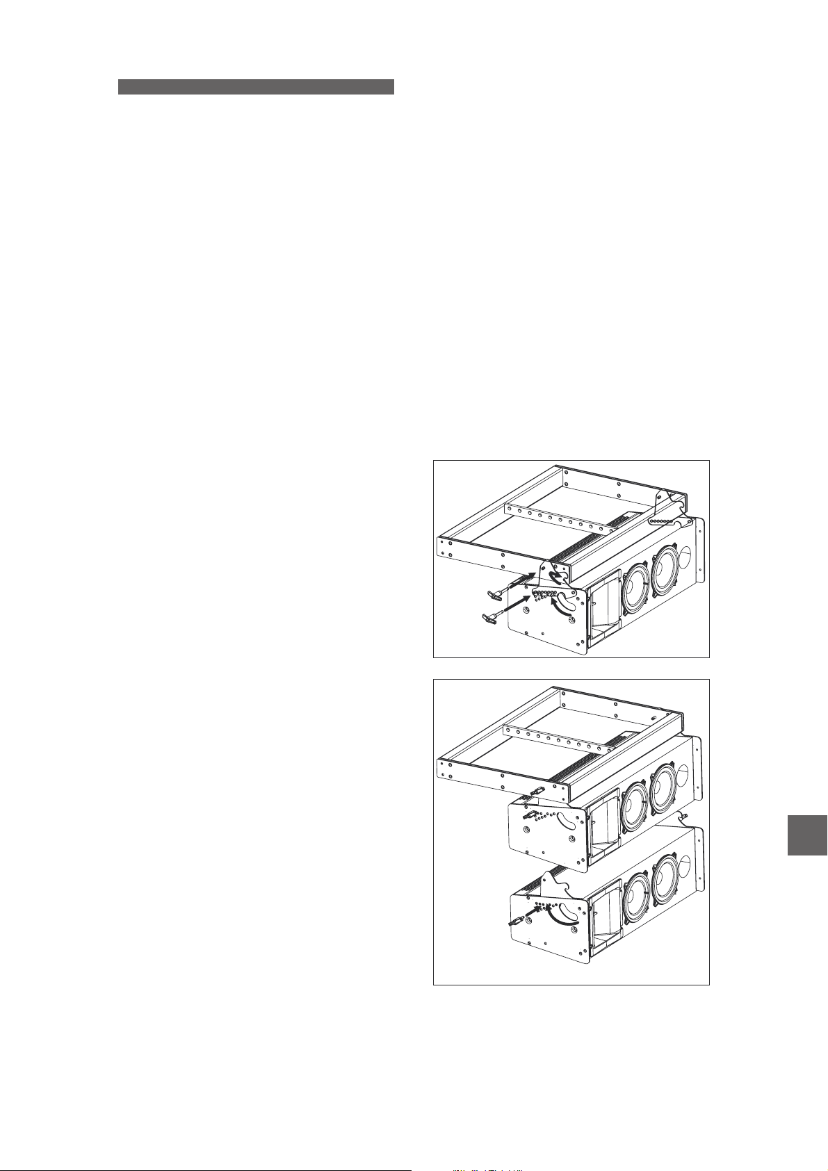
Installing a line array system
Whenever a cluster of only
units is to be assembled the procedure will be as
follows:
First step will be to attach the bumper
to the hoist. The chain sling needs to be attached
to the structure using the shackle provided with
the grid. The shackle will be inserted into the hole
recommended by the software.
The next step will be to mechanically connect
the first to the . In order to do so
rotate the connecting links (1) and then insert the
safety pins through the labeled holes to select the
splay angle between the and the grid
(2). Now both connecting links must be inserted
into the receptacles on the (3). Once this
has been done two more safety pins have to be
inserted to secure the boxes (4). It is highly
advisable to check that all of the safety pins have
been correctly inserted.
variant25A AX-V25
EASE FOCUS
variant 25A
variant 25A/112A
AX-V25
AX-V25
Inspection is the next step after planning and
acquiring all the necessary parts needed to elevate
the systems. All parts, including the hardware
attached to the enclosure, the safety pins, etc.
should be thoroughly inspected before each use.
Units exhibiting deformations, cracks or any other
defect should be replaced with new units.
It is important to establish an inspection routine
for the complete rigging system before each event
or installation as well as establishing the maximum
load specifications of the hoists to be used.
Rigging should be carried out by experts
familiar with the way the system functions and
their characteristics.
On occasions it may be convenient to have
additional tie down points to impede the array
from twisting or swinging.
4
2
3
1
EN
6
5
variant S uideystems G
1
Page 4
The procedure to mechanically connect the
second unit is similar. First rotate the connecting
links (5) in order to select the correct angle by
means of the safety pins (6). In this example the
selected angle is 2º. Once this has been done then
the enclosure must be hung from the first box (7)
and assured by means of one more safety pin (8).
3
4
2
1
7
variant 25A - max 20 units
4
3
8
2
1
EN
The above described procedure applies to the
rest of the units.
The basic procedure to hang the units is as
follows: rotate the connecting links (1) until the
desired angle is reached. Then introduce the
safety pins through the holes labeled with the
desired angle which should have been provided by
the prediction software (2). Now
introduce the connecting links into the receptacles
of the box above and hang the unit from the
rotating point (3). Finally introduce the safety pin
that secures the unit (4). This procedure will be
repeated as many times as enclosures are to be
assembled. This procedure is also identical in case
of flying systems.
2
variant112A
EASE FOCUS
variant 112A AX-V25
set up at 0º.
variant S uideystems G
variant 112A - max 6 units
Note: The vertical angle between the first
and the flying grid can only be
Page 5
Assembling a system with flown subwoofers
variant 18A
The units feature integral rigging
hardware allowing them to be flown independently
or above enclosures.
variant25A
The first step will be to mechanically connect
variant 18A AX-V25
the first to the grid. 6 safety pins
are included in the rear side of the box in order to
do so. First rotate the rear side connecting links by
180º, and then the front side connecting links until
variant 18A AX-V25
the labeled position has been
reached. After that, insert the pin through the hole
labelled (2).
variant18AAX-V25
1
-5º
0º
5º
VARIANT25
0º
AX-V25
VARIA NT 18
1
2
The next step will be to hang one more
unit below the first one. To do so first both
18A
variant
connecting links will be rotated (4), then a safety
pin will be inserted into the hole labeled
variant 18A
(5) on the front side connecting link, and finally
both connecting links will be introduced into the
rigging hardware of the box above and secured by
means of two more safety pins (6).
6
-5º
0º
5º
VARIANT25
0º
AX-V25
VARIANT18
To secure the enclosure to the grid (3) two
more safety pins are needed on each side. Check
that the position of the connecting links are as
shown in the image below.
4
6
If units are to be hung from the
variant 25A
variant 18A
have to be rotated (7), then the safety pin must be
inserted into the hole that provides the desired
angle (8), and finally the connecting links have to
be introduced into the rigging hardware of the box
above and be secured by means of a safety pin on
each side (9).
subwoofers, first the connecting links
4
5
EN
3
3
9
7
8
variant S uideystems G
3
Page 6

The procedure in case of installing
variant 112A
systems is equivalent to the previous mentioned
before.
-5º
0º
5º
VARIANT25
0º
AX-V25
VARIANT18
9
7
8
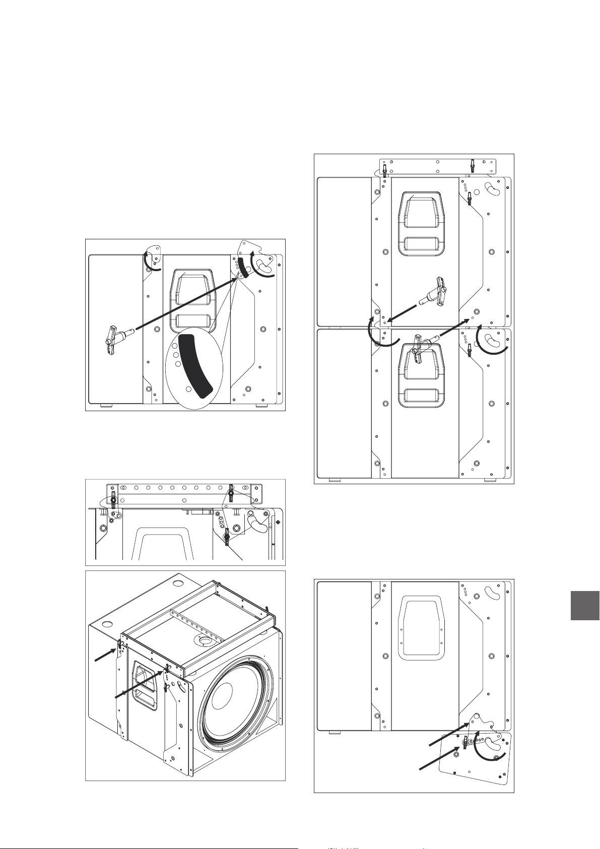
Stacking units on the subs
variant 18A
The units feature integral rigging
hardware which can also be used for stacking
variant 25A/112A
maximum recommended number of
units in this mode is 6. The maximum number of
variant 112A
The splay angles available between both
enclosures are 0º, 5º and -5º.
The first step will be to mechanically connect
the first unit to the
variant 25A variant 18A
enclosure. Four safety pins, which are included in
the box, will be necessary to do so. First rotate the
connecting links (1) on the until the
desired angle is achieved and introduce the safety
pin through the hole labeled with the desired splay
angle (2). The three available angles are 0º, 5º and
-5º. Look at the label on the box.
units on top of them. The
variant 25A
units to be stacked on the subs is 2.
variant 18A
variant18A
2
Before attaching the first to the
1
variant 25A
subwoofer unit, the connecting links must be
rotated (3) until the desired splay angle with the
next unit on top is reached. Once the desired
angle has been reached the safety pins will be
introduced (4) into the corresponding hole.
3
4
In order to attach the unit to the
subwoofer unit, introduce the connecting (5) links
on the into the receptacles on the
variant 25A
variant 18A
. Then two safety pins (6) must be
introduced (one per side) to secure one enclosure
to the other.
variant 25A
EN
5
6
4
variant S uideystems G
Page 7

introduced into the 0º labeled hole, while in the
picture below the safety pin has been introduced
into the +5º labeled hole.
Before attaching the first to the
variant 112AIn the picture above the safety pin has been
subwoofer unit, the connecting links must be
rotated (3) until the desired splay angle with the
next unit on top is reached. Once the desired
angle has been reached the safety pins will be
introduced (4) into the corresponding hole.
The rest of the boxes will be set up using the
above explained procedure for connecting rods
and safety pins ( See page 2).
The first step will be to mechanically connect
the first unit to the
variant 112A variant 18A
enclosure. Four safety pins, which are included in
the box, will be necessary to do so. First rotate the
connecting links (1) on the until the
variant 18A
desired angle is achieved and introduce the safety
pin through the hole labeled with the desired splay
angle (2). The three available angles are 0º, 5º and
-5º. Look at the label on the box.
-5º
0º
5º
VARIANT25
variant18A
4
In order to attach the unit to the
3
variant 112A
subwoofer unit, introduce the connecting (5) links
on the into the receptacles on the
variant 112A
variant 18A
. Then two safety pins (6) must be
introduced (one per side) to secure one enclosure
to the other.
5
6
0º
AX-V25
VARIANT18
EN
2
1
In the graph above the quick release pins have
been inserted in the center hole of the
rigging hardware, so the angle between both
systems is 0º.
If more cabinets are going to be stacked
repeat the process described on page 2.
variant S uideystems G
variant 18A
5
Page 8

System installation using the ceiling support AXC-V25
variant 25A
The units can be set up as a long
array of more than four enclosures (as explained
above) or as a small array of 2, 3 or 4 units. In the
latter case the highly resistant grid
accessory is not necessary. Instead the
AX-V25
AXC-V25
ceiling mount accessory can be used to hang a
cluster of up to four units.
First attach the ceiling mount accessory to the
ceiling or a beam. Before doing so be sure that the
load bearing capability of these elements is
enough. The will be attached to the ceiling
AX-V25
by means of six nº 10 rawlplugs and six 7 x 40
mm screws.
Grower (lock) washer
Metal washer
AXC-V25
Before connecting the first box to the ceiling
mount accessory the two M8x30 DIN965 screws
must be removed from the and
replaced by two M8x35 DIN912.
M8X30 DIN965
variant 25A
M8x35 DIN 912
Rubber washer
Three different washers must be used along
the M8x35 DIN912 screws and placed in the
following order- grower (lock) washer, metal
washer and rubber washer.
In order to hang the rest of the boxes the
captive rigging hardware and safety pins will be
used, and the procedures described on the 4.3
paragraph of this manual will be followed. The
picture below shows three units
variant 25A
hanging from the ceiling.
EN
6
variant S uideystems G
Page 9

When a pair of hook clamps are attached to
the ceiling mount accessory, it can be fixed to a
truss structure such as the one shown in the
picture below:
The accessory can also be used as a
AXC-V25
support for up to two units on a pole
mount accessory, on top of one unit.
To do so the accessory is to be used
upside-down and a special pole mount adaptor
must be fixed to it by means of two M8x35
DIN912 screws, nuts and washers. A 10º splay
angle is recommended in order to achieve a 20º
vertical coverage.
AXC-V25
variant 25A
variant 18A
20º
AXC-V25
Pole Mount
M8x35 DIN912
AXC-ZT
EN
variant S uideystems G
7
Page 10

variant 112A
The units can be set up as a
cluster of more than three enclosures (as explained
above) or as a small array of 2 units. In the latter
case the highly resistant grid accessory is
not necessary. Instead the ceiling mount
AX-V25
AXC-V112
accessory can be used to hang a cluster of up to
four units.
First attach the ceiling mount accessory to the
ceiling or a beam. Before doing so be sure that the
load bearing capability of these elements is
enough. The will be attached to the
AX-V112
ceiling by means of six nº 10 rawlplugs and six 7
x 40 mm screws.
AXC-V112
Grower (lock) washer
Metal washer
M8x35 DIN 912
Rubber washer
Three different washers must be used along
the M8x35 DIN912 screws and placed in the
following order- grower (lock) washer, metal
washer and rubber washer.
EN
Before connecting the first box to the ceiling
mount accessory the two M8x30 DIN965 screws
(per side) must be removed from the
variant 112A
and replaced by two M8x35 DIN912.
M8x30 DIN 965
In order to hang the rest of the boxes the
captive rigging hardware and safety pins will be
used, and the procedures described on the 4.3
paragraph of this manual will be followed. The
picture below shows two units
variant 112A
hanging from the ceiling.
8
variant S uideystems G
Page 11

When a pair of hook clamps ( ) are
attached to the ceiling mount accessory, it can be
fixed to a truss structure such as the one shown in
the picture below:
The accessory can also be used as
AXC-V112
a support for up two unit on a pole
mount accessory, on top of one unit. To
do so the accessory is to be used
upside-down and a special pole mount adaptor
must be fixed to it by means of two M8x35
DIN912 screws, nuts and washers. A 15º splay
angle is recommended in order to achieve a 30º
vertical coverage.
AXC-V112
variant 112A
AXC-AT
variant 18A
AXC-ZT
AXC-V112
M 8x35 DIN912
EN
variant S uideystems G
9
Page 12

System installation using the wall support AXW-V25
Up to three units can be wall
mounted by means of the accessory.
variant 25A
AXW-V25
First the accessory must be fixed to the wall,
making sure in advance that the work load of the
wall allows for it. The wall mount accessory will be
attached to the wall using six nº 10 rawlplugs and
six 7 x 40 mm screws.
Then hang the first unit from the
variant 25A
wall mount accessory. The two M8x30 DIN965
screws have to be removed from each side of the
box and replaced by two M8x35 DIN912 screws.
Grower washer
Metal washer
M8x35 DIN 912
Rubber washer
EN
M8X30 DIN965
Three different washers must be used along
the M8x35 DIN912 screws and placed in the
following order- grower (lock) washer, metal
washer and rubber washer.
Warning!! If three units have to be
variant 25A
hung it is advisable to fix the box in the middle to
the wall mount accessory.
In order to hang the rest of the boxes the
captive rigging hardware and safety pins will be
used, and the procedures described on the 4.3
paragraph of this manual will be followed. The
picture below shows three units fixed to
variant 25A
the wall.
10
variant S uideystems G
Page 13

Page 14

www.dasaudio.com
SI_VA_01_EN
D.A.S. AUDIO, S.A.
C/. Islas Baleares, 24
46988 Fuente del Jarro
Valencia, SPAIN
Tel. 96 134 0525
Tel. Intl. +34 96 134 0860
Fax 96 134 0607
Fax Intl. +34 96 134 0607
D.A.S. AUDIO OF AMERICA, INC.
Sunset Palmetto Park
6816 NW 77th Court.
Miami, FL. 33166 - U.S.A.
TOLL FREE: 1-888DAS4USA
Tel. +1 305 436 0521
Fax +1 305 436 0528
D.A.S. AUDIO ASIA PTE. LTD.
25 Kaki Bukit Crescent #01-00/02-00
Kaki Bukit Techpark 1
Singapore 416256
Tel. +65 6742 0151
Fax +65 6742 0157
 Loading...