

Page 1
User's Manual
series
UX-221 / UX-218 / UX-218-R
Antes de utilizar el equipo, lea la sección
“Precauciones de seguridad” de este manual.
Conserve este manual para futuras consultas.
Before operating the device, please read the
“Safety precautions” section of this manual.
Retain this manual for future reference.
Page 2

CONTENTS
SAFETY PRECAUTIONS
WARRANTY
DECLARATION OF CONFORMITY
INTRODUCTION
CONFIGURATIONS
Example with UX-221
Example with UX-218
SPECIFICATIONS
LINE DRAWINGS
INSTALLATION AND ACCESSORIES
ANNEX : Table for cable selection
3
4
5
6 - 7
8 - 9
10
11
12 - 23
24
Manual del Usuario / UX series / User’s Manual
Page 3
series
UX-221 / UX-218 / UX-218-R
Cajas acústicas pasivas / Passive loudspeaker enclosures
Precauciones de Seguridad
Safety Precautions
Conserve y lea todas estas instrucciones.
Siga todas las advertencias.
El signo de exclamación dentro de un triángulo indica la
existencia de componentes internos cuyo reemplazo puede
afectar a la seguridad.
El doble cuadrado indica equipo de Clase II. The double square indicates Class II device.
Las especificaciones se encuentran en la etiqueta de la parte
posterior del producto.
El colgado del equipo sólo debe realizarse utilizando los herrajes
de colgado recomendados y por personal cualificado.
No exponga este equipo a la lluvia o humedad. No exponga el
equipo a salpicaduras ni coloque sobre él objetos que
contengan líquidos, tales como vasos y botellas. Equipo IP-20.
Este símbolo indica que el presente producto no puede ser
tratado como residuo doméstico normal, sino que debe
entregarse en el correspondiente punto de recogida de equipos
eléctricos y electrónicos.
Equipo diseñado para funcionar entre 15ºC y 45ºC con una
humedad relativa máxima del 95%.
El cableado exterior conectado al equipo requiere de su
instalación por una persona instruida.
Keep these instructions.
Heed all warnings. Follow all instructions.
The exclamation point inside an equilateral triangle indicates the
existence of internal components whose substitution may affect
safety.
The specifications can be found on the rear label of the product.
The appliance should be flown only from the rigging points and
by qualified personnel.
Do not expose this device to rain or moisture. Do not place any
objects containing liquids, such as bottles or glasses, on the top
of the unit. Do not splash liquids on the unit. IP-20 equipment.
This symbol on the product indicates that this product should
not be treated as household waste. Instead it shall be handed
over to the appicable collection point for the recycling of
electrical and electronic equipment.
Working temperature ranges from 15ºC to 45ºC with a relative
humidity of 95%.
The outer wiring connected to the device requires installation by
an instructed person.
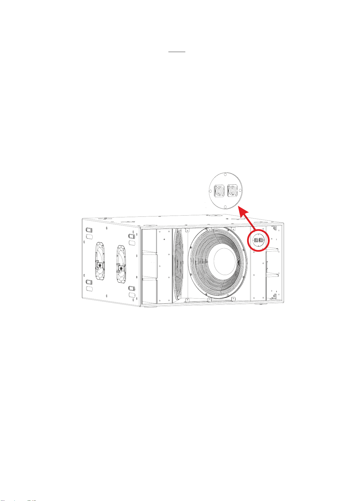
El equipo cuenta con dos conectores de entrada en paralelo
para facilitar la conexión de varias cajas en paralelo.
No emplace altavoces en proximidad a equipos sensibles a
campos magnéticos, tales como monitores de televisión o
material magnético de almacenamiento de datos.
No existen partes ajustables por el usuario en el interior de este
equipo. Cualquier operación de mantenimiento o reparación
debe ser realizada por personal cualificado. Es necesario el
servicio técnico cuando el aparato se haya dañado de alguna
forma, tal como que haya caído líquido o algún objeto en el
interior del aparato, haya sido expuesto a lluvia o humedad, no
funcione correctamente o haya recibido un golpe.
Limpie con un paño seco. No use limpiadores con disolventes.
Note that the two Speakon input connectors are wired in parallel
to provide easy parallel connection of several enclosures.
Do not place loudspeakers in proximity to devices sensitive to
magnetic fields such as television monitors or data storage
magnetic material.
No user serviceable parts inside. Refer all servicing to qualified
service personnel. Servicing is required when the apparatus has
been damaged in any way, such as power-supply cord or plug is
damaged, liquid has been spilled or objects have fallen into the
apparatus, the apparatus has been exposed to rain or moisture,
does not operate normally or has been dropped.
Clean only with a dry cloth. Do not use any solvent based
cleaners.
Manual del Usuario / UX series / User’s Manual
3
Page 4

GARANTÍA
Todos nuestros productos están garantizados por un periodo de 24
meses desde la fecha de compra.
Las garantías sólo serán válidas si son por un defecto de
fabricación y en ningún caso por un uso incorrecto del producto.
Las reparaciones en garantía pueden ser realizadas,
exclusivamente, por el fabricante o el servicio de asistencia técnica
autorizado.
Otros cargos como portes y seguros, son a cargo del comprador
en todos los casos.
Para solicitar reparación en garantía es imprescindible que el
producto no haya sido previamente manipulado e incluir una
fotocopia de la factura de compra.
WARRANTY
All our products are warrantied against any manufacturing defect
for a period of 2 years from date of purchase.
The warranty excludes damage from incorrect use of the product.
All warranty repairs must be exclusively undertaken by the factory
or any of its authorised service centers.
To claim a warranty repair, do not open or intend to repair the
product.
Return the damaged unit, at shippers risk and freight prepaid, to
the nearest service center with a copy of the purchase invoice.
4
Manual del Usuario / UX series / User’s Manual
Page 5

DECLARACIÓN DE CONFORMIDAD
DECLARATION OF CONFORMITY
DAS Audio Group, S.L.
C/ Islas Baleares, 24 - 46988 - Pol. Fuente del Jarro - Valencia. España
(Spain).
Declara que :UX-221, UX-218 y UX-218-R
Declares that :UX-221, UX-218 and UX-218-R
Cumple con los objetivos esenciales de las Directivas:
Abide by essential objectives relating Directives:
l De Baja Tensión / Low Voltage 2014/35/UE
l RoHS 2011/65/UE
l RAEE (WEEE) 2012/19/UE
Y es conforme a las siguientes Normas Armonizadas Europeas:
In accordance with Harmonized European Norms:
l EN 60065:2014.- Audio, video and similar electronic apparatus. Safety
requirements.
l EN 50581:2012.- Technical documentation for the assessment of
electrical and electronic products with respect to the restriction of
hazardous substances.
Manual del Usuario / UX series / User’s Manual
5
Page 6

INTRODUCTION
The UX series is comprised of systems designed in response to demands for high-output ultra-low
frequency solutions. UX-218 and UX-221 are versions of UX series models that have been designed for
external amplification. In addition, model UX-218-R is a version with built-in rigging hardware.
The enclosures incorporate front connectors which allow for easy installation when used in cardioid
configurations.
FEATURES
UX-218 / UX-218-R
- High performance subwoofer system for external
amplification
- Two 18UXN long-excursion loudspeakers
- Front loaded cross-fire configuration
- Solid birch plywood construction
The UX-218 / UX-218-R join the new range of
UX Series subwoofer systems in passive versions.
The UX-218, or UX-218-R, make use of two 18”
18UXN transducers. The new loudspeaker,
designed and manufactured by DAS, offers
impressive features such as a 4" sandwich split
winding voice coil, a remarkable 52 mm peak-topeak excursion, and a powerful FEA optimized
UX-218
FRONT CON NECTORS FOR
CARDIOID C ONFIGURATI ONS
neodymium magnet assembly. Thanks to the
double silicon spider, the 18UXN controls the
moving mass with high linearity. An aluminum
demodulating ring reduces distortion, and effective
ventilation of the voice coil gap provides for a high
thermal rating and reduced power compression.
UX-218-R
The enclosure is constructed using Birch
plywood and makes use of extensive bracing to
eliminate resonances. The woodwork is finished
with the robust DAS ISO-flex protective coating
for durability. A dolly platform with locking casters,
PL-UX218S for UX-218 and PL-UX218RS for UX-218-
R, is available to stack and move the systems.
Protection during transport is provided by the
optional covers available from DAS
UX-218-R is the flying version with built-in
rigging.
6
Manual del Usuario / UX series / User’s Manual
Page 7
UX-221
- High power ultra-low frequency subwoofer system
- Twin 21" Neodymium loudspeakers with 6" voice coils
- Solid 21 mm birch plywood construction
- Impressive 60 mm peak-to-peak excursion
The UX-221 includes two 21" loudspeakers equipped with 6" voice coils and offers a power handling
capacity of 8000 Wpeak for each loudspeaker. The impressive 60 mm peak-to-peak excursion, powerful
neodymium magnet assembly and double silicone spider with optimized compliance provide for commanding
low frequency response.
The enclosure is constructed using 21 mm Birch plywood and makes use of extensive bracing to
eliminate resonances. The woodwork is finished with the robust DAS ISO-flex protective coating for
durability. A dolly platform with locking casters, PL-221S, is available to stack and move the systems.
Protection during transport is provided by the optional covers available from DAS
FRONT CONNECTORS FOR
CARDIOID CONFIGURATIONS
UX-221
Manual del Usuario / UX series / User’s Manual
7
Page 8
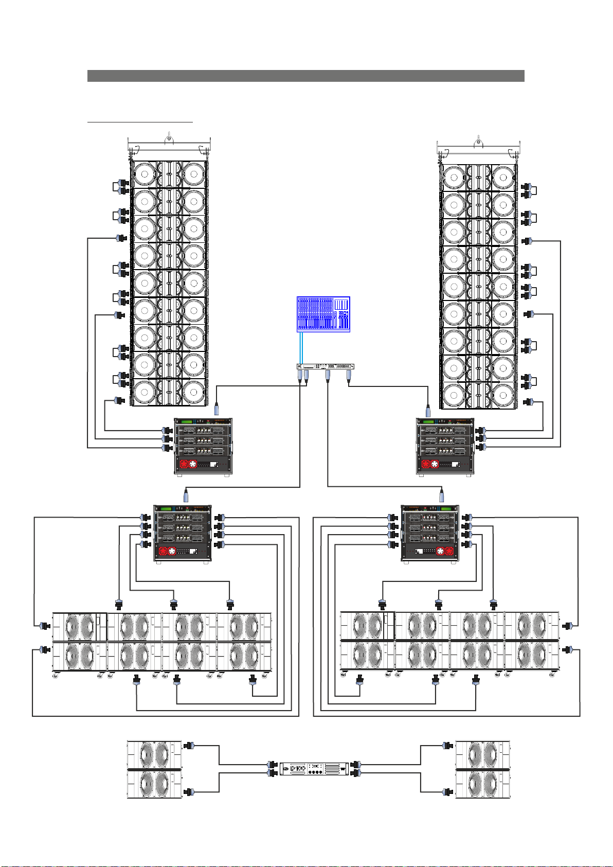
CONFIGURATIONS
Next, find two examples. You will find more configurations on our website.
Example with UX-218
18 x AERO-50
16 x UX-218
Subs: left & right
LINK
LINKLINKLINK
LINK
LINKLINKLINK
LINKLINK
LINKLINK
DSP-4080
EDIT
Power
Bridge A-B
A/P
PRC A
PRC C PRC D
PRC B
Limit
Limit Limit Limit
-24 -24 -24 -24-12 -12 -12 -12-6 -6 -6 -6-3 -3 -3 -3
OCM OCM OCM OCM
Atten. dB
Atten. dB
Atten. dB
-6
-6
-6
-4
-4
-4
-12
-12
-12
-12
-2
-2
-2
0
0
0
Link Link Link
Ch. A Ch. B Ch. C Ch. D
Power
Bridge A-B
A/P
PRC A
PRC C PRC D
PRC B
Limit
Limit Limit Limit
-24 -24 -24 -24-12 -12 -12 -12-6 -6 -6 -6-3 -3 -3 -3
OCM OCM OCM OCM
Atten. dB
Atten. dB
Atten. dB
-6
-6
-6
-4
-4
-4
-12
-12
-12
-12
-2
-2
-2
0
0
0
Link Link Link
Ch. A Ch. B Ch. C Ch. D
Power
Bridge A-B
A/P
PRC A
PRC C PRC D
PRC B
Limit
Limit Limit Limit
-24 -24 -24 -24-12 -12 -12 -12-6 -6 -6 -6-3 -3 -3 -3
OCM OCM OCM OCM
Atten. dB
Atten. dB
Atten. dB
-6
-6
-6
-4
-4
-4
-12
-12
-12
-12
-2
-2
-2
0
0
0
Link Link Link
Ch. A Ch. B Ch. C Ch. D
power distro
Bridge C-D
PROFESSIONAL
Atten. dB
POWER
-6
AMPLIFIER
-4
-2
0
Bridge C-D
PROFESSIONAL
Atten. dB
POWER
-6
AMPLIFIER
-4
-2
0
Bridge C-D
PROFESSIONAL
Atten. dB
POWER
-6
AMPLIFIER
-4
-2
0
FI-Schalter
L1 L2 L3
I
FI4030mA4pol.
o
Power
Bridge A-B
A/P
PRC A
PRC C PRC D
PRC B
Limit
Limit Limit Limit
-24 -24 -24 -24-12 -12 -12 -12-6 -6 -6 -6-3 -3 -3 -3
OCM OCM OCM OCM
Atten. dB
Atten. dB
Atten. dB
-6
-6
-6
-4
-4
-4
-12
-12
-12
-12
-2
-2
-2
0
0
0
Link Link Link
Ch. A Ch. B Ch. C Ch. D
Power
Bridge A-B
A/P
PRC A
PRC C PRC D
PRC B
Limit
Limit Limit Limit
-24 -24 -24 -24-12 -12 -12 -12-6 -6 -6 -6-3 -3 -3 -3
OCM OCM OCM OCM
Atten. dB
Atten. dB
Atten. dB
-6
-6
-6
-4
-4
-4
-12
-12
-12
-12
-2
-2
-2
0
0
0
Link Link Link
Ch. A Ch. B Ch. C Ch. D
Power
Bridge A-B
A/P
PRC A
PRC C PRC D
PRC B
Limit
Limit Limit Limit
-24 -24 -24 -24-12 -12 -12 -12-6 -6 -6 -6-3 -3 -3 -3
OCM OCM OCM OCM
Atten. dB
Atten. dB
Atten. dB
-6
-6
-6
-4
-4
-4
-12
-12
-12
-12
-2
-2
-2
0
0
0
Link Link Link
Ch. A Ch. B Ch. C Ch. D
power distro
Power
Bridge C-D
PROFESSIONAL
Atten. dB
POWER
-6
AMPLIFIER
-4
-2
0
Bridge C-D
PROFESSIONAL
Atten. dB
POWER
-6
AMPLIFIER
-4
-2
0
Bridge C-D
PROFESSIONAL
Atten. dB
POWER
-6
AMPLIFIER
-4
-2
0
FI-Schalter
L1 L2 L3
I
FI4030mA4pol.
o
Manejamos cada UX-218 con un canal de D-100.
±1
±1
We drive each UX-218 loudspeaker with a channel of D-100.
±1
±1
Bridge A-B
A/P
Bridge C-D
PRC A
PRC C PRC D
PRC B
Limit
Limit Limit Limit
-24 -24 -24 -24-12 -12 -12 -12-6 -6 -6 -6-3 -3 -3 -3
OCM OCM OCM OCM
PROFESSIONAL
Atten. dB
Atten. dB
Atten. dB
Atten. dB
POWER
-6
-6
-6
-6
AMPLIFIER
-4
-4
-4
-4
-12
-12
-12
-12
-2
-2
-2
-2
0
0
0
0
Link Link Link
Ch. A Ch. B Ch. C Ch. D
Power
Bridge A-B
A/P
Bridge C-D
PRC A
PRC C PRC D
PRC B
Limit
Limit Limit Limit
-24 -24 -24 -24-12 -12 -12 -12-6 -6 -6 -6-3 -3 -3 -3
OCM OCM OCM OCM
PROFESSIONAL
Atten. dB
Atten. dB
Atten. dB
Atten. dB
POWER
-6
-6
-6
-6
AMPLIFIER
-4
-4
-4
-4
-12
-12
-12
-12
-2
-2
-2
-2
0
0
0
0
Link Link Link
Ch. A Ch. B Ch. C Ch. D
FI-Schalter
L1 L2 L3
I
FI4030mA4pol.
power distro
o
8
Manual del Usuario / UX series / User’s Manual
Page 9

CONFIGURATIONS (cont’d)
Example with UX-221
18 x AERO-50
12 x UX-221
Subs: left & right
LINK
LINKLINKLINK
LINK
LINKLINKLINK
LINKLINK
LINKLINK
DSP-4080
EDIT
Power
Bridge A-B
A/P
Bridge C-D
PRC A
PRC C PRC D
PRC B
Limit
Limit Limit Limit
-24 -24 -24 -24-12 -12 -12 -12-6 -6 -6 -6-3 -3 -3 -3
OCM OCM OCM OCM
Atten. dB
Atten. dB
Atten. dB
Atten. dB
-6
-6
-6
-6
-4
-4
-4
-12
-12
-12
-12
-2
-2
-2
0
0
0
Link Link Link
Ch. A Ch. B Ch. C Ch. D
Power
Bridge A-B
A/P
Bridge C-D
PRC A
PRC C PRC D
PRC B
Limit
Limit Limit Limit
-24 -24 -24 -24-12 -12 -12 -12-6 -6 -6 -6-3 -3 -3 -3
OCM OCM OCM OCM
Atten. dB
Atten. dB
Atten. dB
Atten. dB
-6
-6
-6
-6
-4
-4
-4
-12
-12
-12
-12
-2
-2
-2
0
0
0
Link Link Link
Ch. A Ch. B Ch. C Ch. D
Power
Bridge A-B
A/P
Bridge C-D
PRC A
PRC C PRC D
PRC B
Limit
Limit Limit Limit
-24 -24 -24 -24-12 -12 -12 -12-6 -6 -6 -6-3 -3 -3 -3
OCM OCM OCM OCM
Atten. dB
Atten. dB
Atten. dB
Atten. dB
-6
-6
-6
-6
-4
-4
-4
-12
-12
-12
-12
-2
-2
-2
0
0
0
Link Link Link
Ch. A Ch. B Ch. C Ch. D
power distro
PROFESSIONAL
POWER
AMPLIFIER
-4
-2
0
PROFESSIONAL
POWER
AMPLIFIER
-4
-2
0
PROFESSIONAL
POWER
AMPLIFIER
-4
-2
0
FI-Schalter
L1 L2 L3
I
FI4030mA4pol.
o
Power
Bridge A-B
A/P
Bridge C-D
PRC A
PRC C PRC D
PRC B
Limit
Limit Limit Limit
-24 -24 -24 -24-12 -12 -12 -12-6 -6 -6 -6-3 -3 -3 -3
OCM OCM OCM OCM
Atten. dB
Atten. dB
Atten. dB
Atten. dB
-6
-6
-6
-6
-4
-4
-4
-12
-12
-12
-12
-2
-2
-2
0
0
0
Link Link Link
Ch. A Ch. B Ch. C Ch. D
Power
Bridge A-B
A/P
Bridge C-D
PRC A
PRC C PRC D
PRC B
Limit
Limit Limit Limit
-24 -24 -24 -24-12 -12 -12 -12-6 -6 -6 -6-3 -3 -3 -3
OCM OCM OCM OCM
Atten. dB
Atten. dB
Atten. dB
Atten. dB
-6
-6
-6
-6
-4
-4
-4
-12
-12
-12
-12
-2
-2
-2
0
0
0
Link Link Link
Ch. A Ch. B Ch. C Ch. D
Power
Bridge A-B
A/P
Bridge C-D
PRC A
PRC C PRC D
PRC B
Limit
Limit Limit Limit
-24 -24 -24 -24-12 -12 -12 -12-6 -6 -6 -6-3 -3 -3 -3
OCM OCM OCM OCM
Atten. dB
Atten. dB
Atten. dB
Atten. dB
-6
-6
-6
-6
-4
-4
-4
-12
-12
-12
-12
-2
-2
-2
0
0
0
Link Link Link
Ch. A Ch. B Ch. C Ch. D
power distro
Power
Bridge A-B
A/P
Bridge C-D
PRC A
PRC C PRC D
PRC B
Limit
Limit Limit Limit
-24 -24 -24 -24-12 -12 -12 -12-6 -6 -6 -6-3 -3 -3 -3
PROFESSIONAL
POWER
AMPLIFIER
-4
-2
0
PROFESSIONAL
POWER
AMPLIFIER
-4
-2
0
PROFESSIONAL
POWER
AMPLIFIER
-4
-2
0
FI-Schalter
L1 L2 L3
I
FI4030mA4pol.
o
OCM OCM OCM OCM
Atten. dB
Atten. dB
Atten. dB
-6
-6
-6
-4
-4
-4
-12
-12
-12
-12
-2
-2
-2
0
0
0
Link Link Link
Ch. A Ch. B Ch. C Ch. D
Power
Bridge A-B
A/P
PRC A
PRC C PRC D
PRC B
Limit
Limit Limit Limit
-24 -24 -24 -24-12 -12 -12 -12-6 -6 -6 -6-3 -3 -3 -3
OCM OCM OCM OCM
Atten. dB
Atten. dB
Atten. dB
-6
-6
-6
-4
-4
-4
-12
-12
-12
-12
-2
-2
-2
0
0
0
Link Link Link
Ch. A Ch. B Ch. C Ch. D
Power
Bridge A-B
A/P
PRC A
PRC C PRC D
PRC B
Limit
Limit Limit Limit
-24 -24 -24 -24-12 -12 -12 -12-6 -6 -6 -6-3 -3 -3 -3
OCM OCM OCM OCM
Atten. dB
Atten. dB
Atten. dB
-6
-6
-6
-4
-4
-4
-12
-12
-12
-12
-2
-2
-2
0
0
0
Link Link Link
Ch. A Ch. B Ch. C Ch. D
power distro
PROFESSIONAL
Atten. dB
POWER
-6
AMPLIFIER
-4
-2
0
Bridge C-D
PROFESSIONAL
Atten. dB
POWER
-6
AMPLIFIER
-4
-2
0
Bridge C-D
PROFESSIONAL
Atten. dB
POWER
-6
AMPLIFIER
-4
-2
0
FI-Schalter
L1 L2 L3
I
FI4030mA4pol.
o
±1 ±2 ±1 ±2
Manejamos cada 21" con un canal de D-100.
We drive each 21" loudspeaker with a channel of D-100.
Manual del Usuario / UX series / User’s Manual
9
Page 10

SPECIFICATIONS
Frequency Range (-10 dB)
RMS (Average) Power Handling
On-Axis Sensitivity 1W/1m
Rated Maximum Peak SPL at 1 m
Transducers / Replacement Parts
Nominal Impedance
Recommended Amplifier Power
Enclosure Geometry
Enclosure Material
Color/Finish
Rigging System
Connectors
Dimensions (H x W x D)
Weight
Accessories
UX-221
28 Hz – 125 Hz
2 x 2000W
104 dB SPL
LF: 2 x 21UXN4 / GM-21UXN4
2 x 2800W @ 4 Ohms
Black ISO-flex Paint
Ground Stackable
4 x NL4 speakO N wired ±1 & ±2
60 x 120 x 110 cm
23.6 x 47.2 x 43.3 in
FUN-2-UX221 Cover
PL-221S Stacking dolly
145 dB
2 x 4 Ohms
(1 unit UX-221)
Rectangular
Birch Plywood
130 kg (286 lb)
ANL-2 Eye Bolt
UX-218 / UX-218-R
28 Hz – 125 Hz
2200W
103 dB SPL
LF: 2 x 18UXN / GM-18UXN
3600W @ 4 Ohms
Black ISO-flex Paint
Ground Stackable
Integrated in box design (R)
4 x NL4 speakO N wired ±1
51.4 x 95.2 x 101 cm
20.1 x 37.4 x 39.7 in
51.4 x 101 x 101 cm (R)
20.1 x 39.7 x 39.7 in (R)
129 kg (283.8 lb) (R)
AX-UX218 Rigging system (R)
FUN-2-UX218 Cover
FUN-3-UX218 Cover
PL-UX218S Stacking dolly
PL-UX218RS Stacking dolly (R)
142 dB
4 Ohms
Rectangular
Birch Plywood
87 kg (191.4 lb)
ANL-2 Eye Bolt
DAS Audio Group, S.L. continuously strives to enhance its products through investigation and development. All
specifications are subject to change without prior notice.
10
Manual del Usuario / UX series / User’s Manual
Page 11

LINE DRAWINGS
UX-221
ALL DIMEN SIONS IN MILL IMETERS
UX-218
ALL DIMEN SIONS IN MILL IMETERS
UX-218-R
ALL DIMEN SIONS IN MILL IMETERS
Manual del Usuario / UX series / User’s Manual
11
Page 12

INSTALLATION AND ACCESSORIES
INSTALLATION
When boxes are flown in cardioid configuration, connect the turned units at the front for tidier wiring as
shown in the figures (rear views).
SpkC_10
SpkC_10
Simply plug the cable into the front NL4 speakON connector. Carefully observe the label directions
for proper connection of speakers:
LF1 (±1) & LF2 (±2)
[UX-221]
LF1 & LF2 (±1)
[UX-218 / UX-218-R]
ACCESSORIES
Only experienced installers with adequate knowledge of the equipment and local safety regulations
should fly speaker boxes.
It is the user's responsibility to ensure that the systems to be flown (including flying accessories) comply
with state and local regulations.
The working load limits in this manual are the results of tests by independent laboratories. It is the user's
responsibility to stay within safe limits. It is the user's responsibility to follow and comply with safety factors,
resistance values, periodical supervisions and warnings given in this manual. Product improvement by means
of research and development is ongoing at DAS. Specifications are subject to change without notice.
It’s common industry practice to apply 5:1 safety factors for enclosures and static elements. For slings
and elements exposed to material fatigue due to friction and load variation the following ratios must be met;
5:1 for steel cable slings, 4:1 for steel chain slings and 7:1 for polyester slings. Thus, an element with a
breaking load limit of 1000 kg may be statically loaded with 200 kg (5:1 safety factor) and dynamically loaded
with 142 Kg (7:1 safety factor).
12
Manual del Usuario / UX series / User’s Manual
Page 13

For the working load of each lift motor, a safety factor of 10:1 must be used.
When flying a system, the working load must be lower than the resistance of each individual flying point in
the enclosure, as well as each box.
Hanging hardware should be regularly inspected and suspect units replaced if in doubt. It is highly
recommended that you implement an inspection and maintenance program on flying elements, including
reports to be filled out by the personnel that will carry out the inspections. Local regulations may exist that, in
case of accident, may require you to present evidence of inspection reports and corrective actions after
defects were found.
Absolutely no risks should be taken with regards to public safety.
When flying enclosures from ceiling support structures, extreme care should be taken to assure the load
bearing capabilities of the structures so that the installation is absolutely safe.
All flying accessories that are not supplied by DAS Audio are the user's responsibility. Use at your own
risk when installing flown systems.
ANL-2
The ANL-2 set is an optional set of four eyebolts and four carabiners. (Dimensions in the figure below are
in millimeters)
To install an enclosure using this system, the Allen-head screws of the enclosure must be removed and
replaced by M10 eyebolts on one side of the enclosure. Each rigging point has 200 Kg (440 lb.) working load
limit. Then choose the slings or chains of required load resistance and length, bearing in mind that the length
difference between the front and back slings or chains will determine the vertical orientation. Alternatively,
vertical orientation can be achieved by using bottom eyebolt point at the back.
Each ANL-2 eyebolt has a rated working load of 200 kg. (440 lbs.). Each ANL-2 carabiner has a working
load of 330 kg (726 lbs.). If using other hardware, make sure it is rated to handle the required load.
When using eyebolts, it is important to bear in mind that the rated working load is only true for a load
applied in the plane of the eye, and is significantly reduced for other angles. The drawing illustrates the
concept. The table shows the variation of the working load as a function of the load angle. In the case of the
ANL-2 eyebolt, this means that the 200-kg working load becomes 60 kg at 45 degrees. Do not use eyebolt
flying if the load angle is higher than 45 degrees. For vertical orientation, use of an eyebolt beyond that angle
is possible (see figure below).
Note: when handling heavy loads, always wear appropriate clothing and protective elements
such as gloves, safety shoes, etc.
ANL-2
% Working
Load
0 degrees
100% 65% 30% 25%
Manual del Usuario / UX series / User’s Manual
30 degrees 45 degrees > 45 degrees
13
Page 14

PL-221S
Even though it features integrated rigging points for threaded eyebolts (ANL-2), the most practical use of
UX-221 is stacked. Using the PL-221S dolly platform (WLL = 450 kg), we can stack and transport up to three
UX-221 units; and care should be taken to avoid roll over when moving them, preventing injuries.
As an example, the PL-221S platform, with one UX-221 on top, can be seen in the figure below.
Note: when handling heavy loads, always wear appropriate clothing and protective elements
such as gloves, safety shoes, etc.
PL-221S
PL-UX218S / PL-UX218RS
As for UX-221, a dolly platform is available for transporting and stacking UX-218 units (PL-UX218S, with
WLL = 300 kg), and its rigging version, UX-218-R (PL-UX218RS, with WLL = 400 kg). Using these dolly
platforms we can stack and transport up to three units; and care should be taken to avoid roll over when
moving them.
As an example, these platforms can be seen in the figure below.
Note: when handling heavy loads, always wear appropriate clothing and protective elements
such as gloves, safety shoes, etc.
PL-UX218S
PL-UX218RS
14
Manual del Usuario / UX series / User’s Manual
Page 15

RIGGING
Out of the subwoofers in this manual, only UX-218-R can use a frame designed specifically for flying. UX-
218 can be converted to UX-218-R by means of the KIT-R-UX218 accessory kit. Only in this way will the
enclosure be safely suspended.
Note: when handling heavy loads, always wear appropriate clothing and protective elements
such as gloves, safety shoes, etc.
KIT-R-UX218
Therefore, only UX-218-R can combine with the AX-UX218 accessory frame so that enclosures can be
flown safely. If an extra pick-up point was needed, a PICKUP-AX-AE40S3 center bar could be added. This is
shared with AERO-40A systems, so that PICKUP-AX-AE40S3 allows for easy combining with these line array
systems.
These accessories can be seen in the figures below.
AX-UX218
PICKUP-AX-AE40S3
Next, we'll show an example of a line array system, with the steps on how to assemble it.
The attachment point system is similar to that of the AERO-40A, so, if unfamiliar with it, we suggest you go
through the rigging manual for these systems (RM_AE40_03).
Looking at the enclosure from the side, it can be seen that the frame is symmetrical to optimise a cardioid
arrangement.
Acting on the side controls, the attachment parts will release. We'll know that they are locked into place
once we hear a click, like the front attachment points on AERO-40A, while the side controls will automatically
go back to the initial position when released.
Side controls
Click
Click
Manual del Usuario / UX series / User’s Manual
15
Page 16

Unless it has already been done,
place the enclosure on top of a PL-
UX218RS platform.
Note: Bear in mind that the unit
is not attached to the platform via
quick release pins like other
models.
It is in these preparation steps
that you need to take into account
which units go forward and which
ones go backwards in cardioid
configurations.
In our example, since it is not a
cardioid configuration, all units go
forward.
We'll place another unit on top
of the one we already had with the
guides exposed.
Align the holes and engage the
quick release pins on both sides of
the enclosures as indicated in the
attached figure.
The result can be seen in the
attached figure.
In our examples we will only
stack two units, but, as you may
remember, the platform allows for
stacking up to three units.
16
Manual del Usuario / UX series / User’s Manual
Page 17

Expose the upper guides of the
units like we previously did with the
lower unit.
Place the side parts of the AX-
UX218, each on its correct side
(check the silk screening), lining up
holes of the quick release pins, as
shown.
Next, engage the quick release
pins to attach the AX parts to the
stacked units, on both sides of the
units.
Manual del Usuario / UX series / User’s Manual
17
Page 18

Attach the pick-up point, or pick-up
points, to the holes in the side of the AX
parts indicated by Ease Focus, using the
quick release pins.
Remember that one pick-up bar only
provides a single pick-up point. If another
pick-up point is required, an additional
pick-up bar is needed.
Proceed to hook the assembly to the
motor (or motors, if using two pick-up
points).
18
Manual del Usuario / UX series / User’s Manual
Page 19

Lift the assembly slightly and remove
the dolly platform so as to be able to add
AERO-40A enclosures.
To prepare groups of 4 AERO-40A units
on PL-40S platforms, and select inter-box
angles, consult the rigging manual for
AERO-40A (RM_AE40_03), which can
be found on our website. This manual will
let you become familiar with the use of
the side controls and guides in the
enclosures.
Next, place the first group of AERO-
40A below the group of UX-218-R. In this
example, two groups of 4 AERO-40A will
be attached.
Manual del Usuario / UX series / User’s Manual
19
Page 20

Expose the guides in the upper AERO40A. Once the guides are prepared and
aligned, link the two groups together
using quick release pins.
Observe the indications present in the
silkscreen lettering and use the AERO-40A
rigging manual, RM_AE40_03, as
additional information.
Furthermore, with the help of Ease
Focus software, you will know which pickup holes need to be used so that the final
inclination of the system is the required
one.
20
Manual del Usuario / UX series / User’s Manual
Page 21

Once the two groups have been
joined together, you can start selecting
angles for AERO-40A units according to
the angles indicated by Ease Focus
soft w a re, a n d according to the
indications in the AERO-40A rigging
manual (RM_AE40_03).
Remember that inter-box angles
between AERO-40A units have been 0º,
so as to allow for a safe transport.
Manual del Usuario / UX series / User’s Manual
21
Page 22

Lift the assembly slightly and remove
the PL-40S dolly platform.
Next, lift the assembly so as to leave
room for the second group of AERO-40A
(as stated, our example will use a total of
8 AERO-40A).
For the second group, proceed as
with the first group, setting enclosure
angles before removing the platform.
22
Manual del Usuario / UX series / User’s Manual
Page 23

The final result can be
seen in the attached figure.
F o r disas s e mbly and
transport, it is again advisable
that you go through the
AERO-40A rigging manual
(RM_AE40_03), that can be
found on our website.
UX-218-R units can be
t r a n s p o r t e d in t h re e s
(maximum) using their
platform.
Manual del Usuario / UX series / User’s Manual
23
Page 24

ANNEX : Table for cable selection
This table shows the power loss in % and dB, for different cable lengths and sections shown. It is
recommended that the losses do not exceed 30% in any case (around 3dB). Although it is recommended
minimizing losses, the maximum acceptable losses are usually around 15% (approximately 1.4dB).
24
Manual del Usuario / UX series / User’s Manual
Page 25

www.dasaudio.com
UM_UX-P_03_EN
DAS Audio Group, S.L.
C/. Islas Baleares, 24
46988 Fuente del Jarro
Valencia, SPAIN
Tel. +34 96 134 0860
DAS Audio of America, INC.
6900 NW 52th Street
Miami, FL. 33166 - U.S.A.
TOLL FREE: 1 888 DAS 4 USA
DAS Audio Asia PTE. LTD.
3 Temasek Avenue, Centennial
Tower #34-36
Singapore 039190
Tel. +65 6549 7760
DAS do Brasil LTDA.
Rua Dos Andradas, 382 SL
Santa Efigênia, São Paulo
Brasil. CEP: 01208-000
Tel. +551133330764
 Loading...