

D.A.S. Sound Froce SF-158, Sound Froce SF-10, Sound Froce SF-218, Sound Froce SF-26, Sound Froce SF-212 User Manual
Page 1
User's Manual
Sound Force : Distributed Systems
SF-10 / SF-26 / SF-158 / SF-212 / SF-218
Antes de utilizar el equipo, lea la sección
“Precauciones de seguridad” de este manual.
Conserve este manual para futuras consultas.
Before operating the device, please read the
“Safety precautions” section of this manual.
Retain this manual for future reference.
Page 2

CONTENTS
SAFETY PRECAUTIONS
WARRANTY
DECLARATION OF CONFORMITY
INTRODUCTION
CONFIGURATIONS
4 x SF-221 + 4 x SF-158 (4 WAY) + D series
4 x SF-221 + 4 x SF-158 (3 WAY) + D series
4 x SF-221 + 4 x SF-158 (4 WAY) + DX series
4 x SF-221 + 4 x SF-158 (3 WAY) + DX series
2 x SF-212 + 4 x SF-10
2 x SF-212 + 6 x SF-26
2 x SF-218 + 8 x SF-10
2 x SF-212 + 8 x SF-26
LINE DRAWINGS
SPECIFICATIONS
3
4
5
6 - 7
8 - 11
12
13
INSTALLATION
ACCESSORIES 18 - 22
ANNEX : Table for cable selection
14 - 17
23
Manual del Usuario / SF series / User’s Manual
Page 3
SF-10 / SF-26 / SF-158 / SF-212 / SF-218
Cajas acústicas pasivas / Passive loudspeaker enclosures
Precauciones de Seguridad
Safety Precautions
Conserve y lea todas estas instrucciones.
Siga todas las advertencias.
El signo de exclamación dentro de un triángulo indica la
existencia de componentes internos cuyo reemplazo puede
afectar a la seguridad.
El doble cuadrado indica equipo de Clase II. The double square indicates Class II device.
Las especificaciones se encuentran en la etiqueta de la parte
posterior del producto.
El colgado del equipo sólo debe realizarse utilizando los herrajes
de colgado recomendados y por personal cualificado. No
cuelgue la caja de las asas.
No exponga este equipo a la lluvia o humedad. No exponga el
equipo a salpicaduras ni coloque sobre él objetos que
contengan líquidos, tales como vasos y botellas. Equipo IP-20.
Este símbolo indica que el presente producto no puede ser
tratado como residuo doméstico normal, sino que debe
entregarse en el correspondiente punto de recogida de equipos
eléctricos y electrónicos.
Equipo diseñado para funcionar entre -25ºC y 45ºC. La
humedad relativa máxima del 95%.
El cableado exterior conectado al equipo requiere de su
instalación por una persona instruida o el uso de cables flexibles
ya preparados.
Keep these instructions.
Heed all warnings. Follow all instructions.
The exclamation point inside an equilateral triangle indicates the
existence of internal components whose substitution may affect
safety.
The specifications can be found on the rear label of the product.
The appliance should be flown only from the rigging points and
by qualified personnel. Do not suspend the box from the
handles.
Do not expose this device to rain or moisture. Do not place any
objects containing liquids, such as bottles or glasses, on the top
of the unit. Do not splash liquids on the unit. IP-20 equipment.
This symbol on the product indicates that this product should
not be treated as household waste. Instead it shall be handed
over to the applicable collection point for the recycling of
electrical and electronic equipment.
Working temperature ranges from -25ºC to 45ºC. The maximum
relative humidity of 95%.
The outer wiring connected to the device requires installation by
an instructed person or the use of a flexible cable already
prepared.
El equipo cuenta con dos conectores de entrada en paralelo
para facilitar la conexión de varias cajas en paralelo.
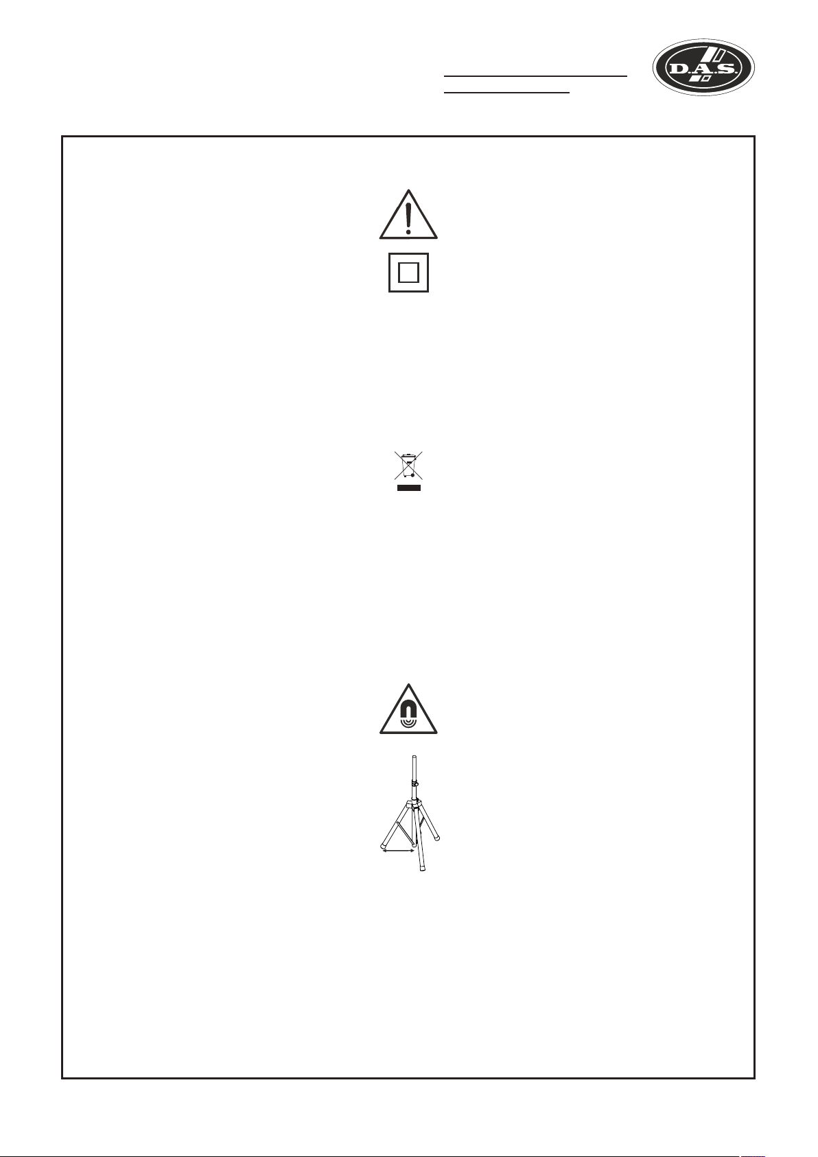
No emplace altavoces en proximidad a equipos sensibles a
campos magnéticos, tales como monitores de televisión o
material magnético de almacenamiento de datos.
Para las cajas con vaso para trípode, la altura máxima de
seguridad desde el suelo a la base de la caja montada sobre
trípode modelo TRD-2, con pies a 55 cm del eje del trípode, es:
SF-26------------------> 130 cm
SF-10------------------> 125 cm
No existen partes ajustables por el usuario en el interior de este
equipo. Cualquier operación de mantenimiento o reparación
debe ser realizada por personal cualificado. Es necesario el
servicio técnico cuando el aparato se haya dañado de alguna
forma, tal como que haya caído líquido o algún objeto en el
interior del aparato, haya sido expuesto a lluvia o humedad, no
funcione correctamente o haya recibido un golpe.
Limpie con un paño seco. No use limpiadores con disolventes.
Note that the two Speakon input connectors are wired in parallel
to provide easy parallel connection of several enclosures.
Do not place loudspeakers in proximity to devices sensitive to
magnetic fields such as television monitors or data storage
magnetic material.
For enclosures with tripod socket, the maximum safety height
from floor to bottom of enclosure when mounting on a TRD-2
tripod, with legs spread 55cm from the central pole, is:
SF-26------------------> 130 cm
SF-10------------------> 125 cm
55 cm
No user serviceable parts inside. Refer all servicing to qualified
service personnel. Servicing is required when the apparatus has
been damaged in any way, such as power-supply cord or plug is
damaged, liquid has been spilled or objects have fallen into the
apparatus, the apparatus has been exposed to rain or moisture,
does not operate normally or has been dropped.
Clean only with a dry cloth. Do not use any solvent based
cleaners.
Manual del Usuario / SF series / User’s Manual
3
Page 4

GARANTÍA
Todos nuestros productos están garantizados por un periodo de 24
meses desde la fecha de compra.
Las garantías sólo serán válidas si son por un defecto de
fabricación y en ningún caso por un uso incorrecto del producto.
Las reparaciones en garantía pueden ser realizadas,
exclusivamente, por el fabricante o el servicio de asistencia técnica
autorizado.
Otros cargos como portes y seguros, son a cargo del comprador
en todos los casos.
Para solicitar reparación en garantía es imprescindible que el
producto no haya sido previamente manipulado e incluir una
fotocopia de la factura de compra.
WARRANTY
All D.A.S. products are warrantied against any manufacturing defect
for a period of 2 years from date of purchase.
The warranty excludes damage from incorrect use of the product.
All warranty repairs must be exclusively undertaken by the factory
or any of its authorised service centers.
To claim a warranty repair, do not open or intend to repair the
product.
Return the damaged unit, at shippers risk and freight prepaid, to
the nearest service center with a copy of the purchase invoice.
4
Manual del Usuario / SF series / User’s Manual
Page 5

DECLARACIÓN DE CONFORMIDAD
DECLARATION OF CONFORMITY
D.A.S. Audio, S.A.
C/ Islas Baleares, 24 - 46988 - Pol. Fuente del Jarro - Valencia. España
(Spain).
Declara que :SF-10 / SF-26 / SF-158 / SF-212 / SF-218
Declares that :SF-10 / SF-26 / SF-158 / SF-212 / SF-218
Cumple con los objetivos esenciales de las Directivas:
Abide by essential objectives relating Directives:
l Directiva de Baja Tensión (Low Voltage Directive) 2014/35/UE
l Directiva RoHS 2011/65/UE
l Directiva RAEE (WEEE) 2012/19/UE
Y es conforme a las siguientes Normas Armonizadas Europeas:
In accordance with Harmonized European Norms:
l EN 60065:2014.- Audio, video and similar electronic apparatus. Safety
requirements.
l EN 50581:2012.- Technical documentation for the assessment of
electrical and electronic products with respect to the restriction of
hazardous substances.
Manual del Usuario / SF series / User’s Manual
5
Page 6
INTRODUCTION
The Sound Force (SF) series has been designed for today´s high-level dance venues where exceptional
sound, imposing power and impressive looks are key requisites.
Thanks to the modularity of the series, the designers of the rooms have a variety of combinations to midhigh, medium-low and subwoofers that can be adapted to specific local needs.
Designed for performance and reliability, built to exacting standards Sound Force by D.A.S. Audio .The
first choice for high-level dance clubs worldwide.
Features
SF-26
- Twin 6" loudspeakers, 6P
– M-34 compression driver of 1"
– Vertical or horizontal positioning
– Threaded fixing points for wall mounts
– Pole mount accessories
The SF-26 employs twin 6P woofers for low frequency
reproduction. The M-34 compression driver provides
brilliant highs. The birch plywood cabinet construction
offers an ultra-compact design. Precise coverage and
control in either the horizontal and vertical position is
possible thanks to the symmetrical 80° horn geometry.
The cabinets can be permanently installed by way of the
SF-26
optional “U” brackets and accessories which allow for
multiple configurations. Four threaded fixing points for the
AXW-1 adjustable wall mount and stand mounting
accessories augment adaptability. A robust steel grille
internally lined with acoustically transparent filter cloth
protects components. Optional colors are available by
special order.
SF-10
SF-10
– Single 10" loudspeaker
– Compression driver with 1.75" polymer diafragm
– Threaded fixing points for wall mounts
– Pole mount socket
The SF-10 employs a single 10" woofer, 10P, for low
frequency reproduction. The M-60N compression driver
with 1.75" high tech polymer diaphragm provides brilliant
highs. The birch plywood cabinet construction offers an
ultra-compact design. Precise coverage and control with
its 110º x 50º horn geometry. The cabinets can be
permanently installed by way of the optional “U” brackets
and accessories which allow for multiple configurations.
Four threaded fixing points for the AXW-3 adjustable wall
mount and a pole mount socket augment adaptability. A
robust steel grille which shares the design scheme of the
other Sound Force models. Optional colors are available
by special order.
6
Manual del Usuario / SF series / User’s Manual
Page 7
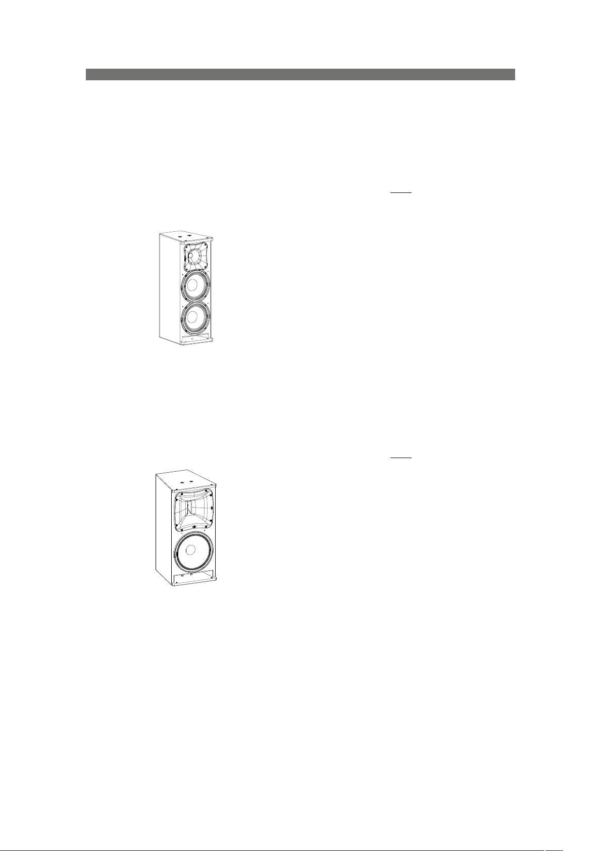
SF-158
SF-158
- Three-way full-range system
– 1 x 15GNR horn loaded bass loudspeaker
– 1 x 8AN horn loaded mid-range loudspeaker
– M-75N neodymium compression driver
– Selectable biamp/triamp operating modes
– Tight 40º x 30º coverage angles
– Rotatable horn for vertical or horizontal positioning
The SF-158 3-way, full-range system is designed to
provide the Sound Force series with a powerful stand-alone
solution. A horn loaded 15" bass, and an 8" mid range in
a bullet-type loading device handle the low to mid range.
The M-75N neodymium compression driver provides
exceptional high frequency reproduction. The SF-158 can
be used in either the vertical or horizontal position thanks
to its rotatable mid-high horn assembly. Selectable biamp
or triamp operation is possible. Custom colors can be
ordered.
SF-212
- Compact band-pass subwoofer system
- Dual 12” low frequency loudspeakers and 3" coil
- Enclosure designed for an easy stacking
SF-212
SF-218
The SF-212 is a band-pass subwoofer system with
dual 12P low frequency loudspeakers. The loudspeaker is
protected by a perforated steel grille, sealed against
corrosion using a powder coat finish. The birch plywood
cabinet construction offers an ultra-compact design which
is available in black or white. The SF-212 is designed for
use in active systems. The handles make moving easy.
Custom colors can be ordered.
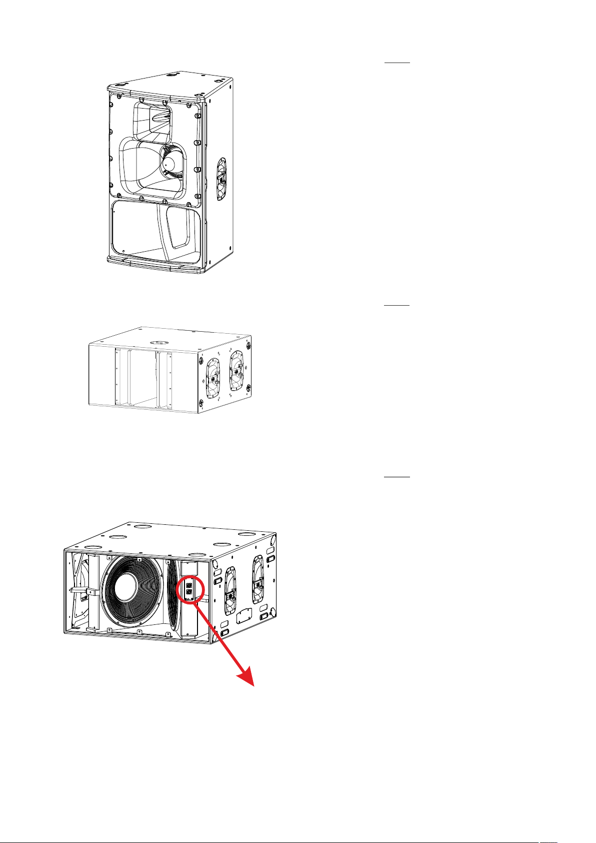
SF-218
- High performance subwoofer system for external
amplification
- Two 18UXN long-excursion loudspeakers
- Front loaded cross-fire configuration
- Solid birch plywood construction
The SF-218, make use of two 18” 18UXN transducers.
The new loudspeaker, designed and manufactured by
D.A.S., offers impressive features such as a 4" sandwich
split winding voice coil, a remarkable 52 mm peak-topeak excursion, and a powerful FEA optimized
neodymium magnet assembly. Thanks to the double
silicon spider, the 18UXN controls the moving mass with
high linearity. An aluminum demodulating ring reduces
distortion, and effective ventilation of the voice coil gap
provides for a high thermal rating and reduced power
compression.
FRONT CON NECTORS
FOR CARDI OID
CONFIGUR ATIONS
The enclosure is constructed using Birch plywood and
makes use of extensive bracing to eliminate resonances.
The woodwork is finished with the robust D.A.S. ISO-flex
protective coating for durability. A dolly platform with
locking casters, PL-UX218S, is available to stack and move
the systems (up to 3 units). Protection during transport is
provided by the optional covers available from D.A.S.
Custom colors can be ordered.
Manual del Usuario / SF series / User’s Manual
7
Page 8

CONFIGURATIONS
Next, find eight examples.
4 x SF-221 + 4 x SF-158 (4 WAY) + D series
CONNECTOR NL8
L R
±1 / ±2 / ±3
CONNECTOR NL8
D100
±1 / ±2 / ±3
CONNECTOR NL8
D100
D100
±1 / ±2 ±1 / ±2
CONNECTOR NL4 CONNECTOR NL4
±1 / ±2
CONNECTOR NL4
D100
±1 / ±2
CONNECTOR NL4
CONNECTOR NL8
4 x SF-221 + 4 x SF-158 (3 WAY) + D series
CONNECTOR NL8 CONNECTOR NL8
L R
±1 / ±2
CONNECTOR NL8
D100
D100
±1 / ±2
CONNECTOR NL4 CONNECTOR NL4
±1 / ±2
CONNECTOR NL4
D100
±1 / ±2
CONNECTOR NL8
±1 / ±2
±1 / ±2
CONNECTOR NL4
8
Manual del Usuario / SF series / User’s Manual
Page 9

CONFIGURATIONS (cont’d)
CONNECTOR NL8
4 x SF-221 + 4 x SF-158 (4 WAY) + DX series
L R
PROTECTION
DX SERIES DSP
BRIDGE 1+2
PROCESSING POWER AMPLIFIER
±1 / ±2 / ±3
CONNECTOR NL8
±1 / ±2
CONNECTOR NL4
±1 / ±2
CONNECTOR NL4
MUTE
CLIP
0
6
AUX 1-4
12
18
24
IN A-D
BANK
EDIT
LIM LIM LIM LIM
3 3 3 3
6 6 6 6
12 12 12 12
18 18 18 18
24 24 24 24
-12 -12 -12 -12
-20 -20 -20 -20
- - - -
DX SERIES
LIM LIM LIM LIM
3 3 3 3
6 6 6 6
12 12 12 12
18 18 18 18
24 24 24 24
-12 -12 -12 -12
-20 -20 -20 -20
- - - -
DX SERIES
LIM LIM LIM LIM
3 3 3 3
6 6 6 6
12 12 12 12
18 18 18 18
24 24 24 24
-12 -12 -12 -12
-20 -20 -20 -20
- - - -
DX SERIES
1 2 3 4
L+4
L+4
L+4
G.R.
LIM
LIM
LIM
1
6
6
6
2
4
12
12
12
8
18
18
18
16
24
24
24
A B C D
LINK LINKLINK
-6 -6 -6 -6
-4 -4 -4 -4
-2 -2 -2 -2
0dB 0dB 0dB 0dB
LINK LINKLINK
-6 -6 -6 -6
-4 -4 -4 -4
-2 -2 -2 -2
0dB 0dB 0dB 0dB
LINK LINKLINK
-6 -6 -6 -6
-4 -4 -4 -4
-2 -2 -2 -2
0dB 0dB 0dB 0dB
BRIDGE 3+4
BACK NEXT
MENU
STBY
ADJUST
REMOTE
DIGITAL IN
NETWORK AUDIO
ENTER
QUIT
DX SERIES DSP
PROCESSING POWER AMPLIFIER
AUX OUTPUTS
PROTECTION
BRIDGE 1+2
BRIDGE 3+4
STBY
POWER
ANALOGUE
NETWORK AUDIO
PROTECTION
BRIDGE 1+2
BRIDGE 3+4
STBY
POWER
ANALOGUE
NETWORK AUDIO
PROTECTION
BRIDGE 1+2
BRIDGE 3+4
STBY
POWER
ANALOGUE
NETWORK AUDIO
±1 / ±2 / ±3
CONNECTOR NL8
±1 / ±2
CONNECTOR NL4
±1 / ±2
CONNECTOR NL4
CONNECTOR NL8
4 x SF-221 + 4 x SF-158 (3 WAY) + DX series
CONNECTOR NL8 CONNECTOR NL8
±1 / ±2
CONNECTOR NL8
±1 / ±2
CONNECTOR NL4
±1 / ±2
CONNECTOR NL4
L R
PROTECTION
DX SERIES DSP
BRIDGE 1+2
PROCESSING POWER AMPLIFIER
BRIDGE 3+4
BACK NEXT
MENU
STBY
MUTE
1 2 3 4
ADJUST
L+4
L+4
L+4
CLIP
G.R.
REMOTE
LIM
LIM
LIM
1
0
6
6
6
2
6
AUX 1-4
DIGITAL IN
4
12
12
12
12
8
18
18
18
18
16
24
24
24
24
IN A-D
NETWORK AUDIO
A B C D
ENTER
QUIT
BANK
DX SERIES DSP
EDIT
PROCESSING POWER AMPLIFIER
AUX OUTPUTS
LINK LINKLINK
PROTECTION
BRIDGE 1+2
LIM LIM LIM LIM
3 3 3 3
BRIDGE 3+4
6 6 6 6
12 12 12 12
18 18 18 18
24 24 24 24
-6 -6 -6 -6
STBY
-4 -4 -4 -4
-12 -12 -12 -12
-2 -2 -2 -2
POWER
-20 -20 -20 -20
- - - -
ANALOGUE
0dB 0dB 0dB 0dB
NETWORK AUDIO
DX SERIES
LINK LINKLINK
PROTECTION
BRIDGE 1+2
LIM LIM LIM LIM
3 3 3 3
BRIDGE 3+4
6 6 6 6
12 12 12 12
18 18 18 18
24 24 24 24
-6 -6 -6 -6
STBY
-4 -4 -4 -4
-12 -12 -12 -12
-2 -2 -2 -2
POWER
-20 -20 -20 -20
- - - -
ANALOGUE
0dB 0dB 0dB 0dB
NETWORK AUDIO
DX SERIES
Manual del Usuario / SF series / User’s Manual
±1 / ±2
CONNECTOR NL8
±1 / ±2
CONNECTOR NL4
±1 / ±2
CONNECTOR NL4
9
Page 10

CONFIGURATIONS (cont’d)
2 x SF-212 + 4 x SF-10
±1
CONNECTOR NL4
L R
AUX 1-4
IN A-D
BANK
DX SERIES DSP
PROCESSING POWER AMPLIFIER
MUTE
1 2 3 4
L+4
CLIP
LIM
0
6
6
12
12
18
18
24
24
A B C D
EDIT
PROTECTION
BRIDGE 1+2
BRIDGE 3+4
BACK NEXT
MENU
STBY
ADJUST
L+4
L+4
G.R.
REMOTE
LIM
LIM
1
6
6
2
DIGITAL IN
4
12
12
8
18
18
16
24
24
NETWORK AUDIO
ENTER
QUIT
DX SERIES DSP
PROCESSING POWER AMPLIFIER
±1 ±1
CONNECTOR NL4 CONNECTOR NL4
2 x SF-212 + 6 x SF-26
±1
CONNECTOR NL4
10
±1
CONNECTOR NL4
L R
AUX 1-4
IN A-D
BANK
DX SERIES DSP
PROCESSING POWER AMPLIFIER
MUTE
1 2 3 4
L+4
CLIP
LIM
0
6
6
12
12
18
18
24
24
A B C D
EDIT
PROTECTION
BRIDGE 1+2
BRIDGE 3+4
BACK NEXT
MENU
STBY
ADJUST
L+4
L+4
G.R.
REMOTE
LIM
LIM
1
6
6
2
DIGITAL IN
4
12
12
8
18
18
16
24
24
NETWORK AUDIO
ENTER
QUIT
DX SERIES DSP
PROCESSING POWER AMPLIFIER
±1 ±1
CONNECTOR NL4 CONNECTOR NL4
Manual del Usuario / SF series / User’s Manual
CONNECTOR NL4
±1
Page 11

CONFIGURATIONS (cont’d)
±1 ±1
CONNECTOR NL4 CONNECTOR NL4
±1 ±1
CONNECTOR NL4 CONNECTOR NL4
2 x SF-218 + 8 x SF-10
PROTECTION
DX SERIES DSP
BRIDGE 1+2
PROCESSING POWER AMPLIFIER
BRIDGE 3+4
BACK NEXT
MENU
STBY
MUTE
1
2 3 4
ADJUST
L+4
L+4
L+4
CLIP
G.R.
REMOTE
LIM
LIM
LIM
1
0
6
6
6
2
6
AUX 1-4
DIGITAL IN
4
12
12
12
12
8
18
18
18
18
16
24
24
24
24
IN A-D
NETWORK AUDIO
A B C D
ENTER
QUIT
BANK
DX SERIES DSP
EDIT
PROCESSING POWER AMPLIFIER
2 x SF-212 + 8 x SF-26
±1 ±1
CONNECTOR NL4 CONNECTOR NL4
PROTECTION
DX SERIES DSP
BRIDGE 1+2
PROCESSING POWER AMPLIFIER
BRIDGE 3+4
BACK NEXT
MENU
STBY
MUTE
1 2 3 4
ADJUST
L+4
L+4
L+4
CLIP
G.R.
REMOTE
LIM
LIM
LIM
1
0
6
6
6
2
6
AUX 1-4
IN A-D
BANK
±1 ±1
CONNECTOR NL4 CONNECTOR NL4
EDIT
12
18
24
12
18
24
A B C D
DIGITAL IN
4
12
12
8
18
18
16
24
24
NETWORK AUDIO
ENTER
QUIT
DX SERIES DSP
PROCESSING POWER AMPLIFIER
Manual del Usuario / SF series / User’s Manual
11
Page 12

LINE DRAWINGS
ALL DIMEN SIONS IN MILL IMETERS
SF-10SF-26SF-158SF-212SF-218
12
Manual del Usuario / SF series / User’s Manual
Page 13

Page 14

INSTALLATION
Connectors
The D.A.S. SF series is designed to facilitate the connection for installations, so it has been provided with
two types of connectors: the NL4 type (NL8 in SF-158) is standard for professional audio equipment. These
terminals are connected in parallel, so that we can carry the amplified audio signal up to a device and we can
forward it to the next box, very easily. The polarity of the connectors and other important information for
proper connection is indicated on the labels.
S :witch to operating mode
BI-AMPLIFIED - TRI-AMPLIFIED
BI-AMPLIFIED
TRI-AMPLIFIED
EUROPEAN
PRODUCT
SOUND
FO RC E
55 Hz - 20 kHz
www.dasaudio.com
10
800 W
400 W
8 W
Rotatable horns
Rest of models with NL4
(+1 -1)
When we install the equipment horizontally, it is advisable to rotate the horn to maintain coverage ranges.
In the SF-10 model, the horn can be rotated: remove the grille, unscrew the horn and turn it 90º, screw the
horn and grille back in place. The model SF-158 has been equipped with a modular set of two horns that can
be rotated at the same time, as shown in the following figures:
1 2
14
3 4
Manual del Usuario / SF series / User’s Manual
Page 15

Coverages
The SF-10, SF-26 and SF-158 models are designed with trapezoid enclosures to very easily achieve the
desired coverages in fixed installations. Next, we show the horizontal coverage with three units of SF-158, as
example (enclosures seen from above) :
40º
SF-158
40º
60º
40º
100º
Manual del Usuario / SF series / User’s Manual
15
Page 16

As examples, next, you will see three coverages with Sound Force series models.
Angle between SF-10: 80º (separate cabinets at the front 40cm)
Total Horizontal Coverage angle: 160º
Shown SPL Map at 4kHz
16
Angle between SF-158: 30º (side to side)
Total Horizontal Coverage angle: 90º
Shown SPL Map at 4kHz
Manual del Usuario / SF series / User’s Manual
Page 17

Angle between SF-158: 30º (side to side)
Total Horizontal Coverage angle: 100º
Shown SPL Map at 4kHz
Note: This example as shown on page 15.
Manual del Usuario / SF series / User’s Manual
17
Page 18

ACCESSORIES
To perform any operations related to flying the system, read the present document first, and act on the
warnings and advice given.
The goal is to allow the user to become familiar with the mechanical elements required to fly the acoustic
system, as well as the safety measures to be taken during set-up and teardown.
Only experienced installers with adequate knowledge of the equipment and local safety regulations
should fly speaker boxes.
It is the user's responsibility to ensure that the systems to be flown (including flying accessories) comply
with state and local regulations.
The working load limits in this manual are the results of tests by independent laboratories. It is the user's
responsibility to stay within safe limits. It is the user's responsibility to follow and comply with safety factors,
resistance values, periodical supervisions and warnings given in this manual.
Product improvement by means of research and development is on going at D.A.S. Specifications are
subject to change without notice.
To this date, there is no international standard regarding the flying of acoustic systems. However, it is
common practice to apply 5:1 safety factors for enclosures and static elements.
For slings and elements exposed to material fatigue due to friction and load variation the following ratios
must be met; 5:1 for steel cable slings, 4:1 for steel chain slings and 7:1 polyester slings.
Thus, an element with a breaking load limit of 1000 kg may be statically loaded with 200 kg (5:1 safety
factor) and dynamically loaded with 142 Kg (7:1 safety factor).
The load capacity, of each lift motor, should be correspond to a safety factor of 10:1.
When flying a system, the working load must be lower than the resistance of each individual flying point in
the enclosure, as well as each box.
Hanging hardware should be regularly inspected and suspect units replaced if in doubt.
This is important to avoid injury and absolutely no risks should be taken in this respect. It is highly
recommended that you implement an inspection and maintenance program on flying elements, including
reports to be filled out by the personnel that will carry out the inspections.
Local regulations may exist that, in case of accident, may require you to present evidence of inspection
reports and corrective actions after defects were found.
Absolutely no risks should be taken with regards to public safety.
When flying enclosures from ceiling support structures, extreme care should be taken to assure the load
bearing capabilities of the structures so that the installation is absolutely safe.
Do not fly enclosures from unsafe structures.
Consult a certified professional if needed.
All flying accessories that are not supplied by D.A.S. Audio are the user's responsibility. Use at your own
risk.
ANL-2
18
0 Degrees
% Working
Load
Manual del Usuario / SF series / User’s Manual
100% 65% 30% 25%
30 Degrees 45 Degrees More than 45
Degrees
Page 19

To hang the units, the Allen-head screws must be removed and replaced by M10 eyebolts on one side of
the enclosure. Each rigging point has 200 kg (440 lb) working load limit.
Then choose the slings or chains of required load resistance and length, bearing in mind that the length
difference between the front and back slings or chains will determine the vertical orientation. Alternatively, the
back bottom eyebolt points can be used to provide vertical orientation.
The ANL-2 set is an optional set of four eyebolts and four carabiners. (Dimensions are in milimetres).
Each ANL-2 eyebolt has a rated working load of 200 kg. (440 lb). Each ANL-2 carabiner has a working
load of 330 kg (726 lb). If using other hardware, make sure it is rated to handle the required load.
When using eyebolts it is important to bear in mind that the rated working load is only true for a load
applied in the plane of the eye, and is significantly reduced for other angles. The drawing illustrates the
concept.
The table shows the variation of the working load as a function of the load angle. In the case of the ANL-2
eyebolt, this means that the 200 kg working load becomes 60 kg at 45 degrees. Do not use eyebolt flying if
the load angle is higher than 45 degrees.
Note: As always, when we handle heavy loads, we should wear appropriate clothing and
protective elements such as gloves, safety shoes, etc.
Next, you will see some examples, both horizontal and vertical array.
Frontal view Side view
Horizontal Array
Manual del Usuario / SF series / User’s Manual
Rear view
19
Page 20

Frontal view Side view
Vertical Array
Stacked Systems
However, the most common will be the stacking systems. Below is an example (2x SF-158 upon 2x
SF-221), step by step.
First, we will stack 2x SF-221 as shown below, joining the boxes with 4x AX-SF2.
Rear view
20
Manual del Usuario / SF series / User’s Manual
Page 21

Now, we will screw the AX-SF2158 over them.
Next, we will screw 2x SF-158 to the AX-SF2158.
Manual del Usuario / SF series / User’s Manual
21
Page 22

Finally, we will join the SF-158 units with 2x AX-SF2.
As can be seen, the result is a solid stacked system.
22
Manual del Usuario / SF series / User’s Manual
Page 23

ANNEX : Table for cable selection
This table shows the power loss in % and dB, for different cable lengths and sections shown. It is
recommended that the losses do not exceed 30% in any case (around 3dB). Although it is recommended
minimizing losses, the maximum acceptable losses are usually around 15% (approximately 1.4dB).
Manual del Usuario / SF series / User’s Manual
23
Page 24

www.dasaudio.com
UM_SF_04_EN
D.A.S. AUDIO, S.A.
C/. Islas Baleares, 24
46988 Fuente del Jarro
Valencia, SPAIN
Tel. +34 96 134 0860
D.A.S. AUDIO OF AMERICA, INC.
6900 NW 52th Street
Miami, FL. 33166 - U.S.A.
TOLL FREE: 1 888 DAS 4 USA
D.A.S. AUDIO ASIA PTE. LTD.
3 Temasek Avenue, Centennial Tower #34-36
Singapore 039190
Tel. +65 6549 7760
 Loading...