

Page 1

User's Manual
Sound Force : Monitor
SF-20AL / SF-20AR / SF-1521A
Antes de utilizar el equipo, lea la sección
“Precauciones de seguridad” de este manual.
Conserve este manual para futuras consultas.
Before operating the device, please read the
“Safety precautions” section of this manual.
Retain this manual for future reference.
Page 2

CONTENTS
SAFETY PRECAUTIONS
WARRANTY
DECLARATION OF CONFORMITY
INTRODUCTION
CONFIGURATIONS
SPECIFICATIONS
LINE DRAWINGS
DESCRIPTION OF AMPLIFIERS
INSTALLATION AND ACCESSORIES
ANNEX II: Line connections: unbalanced and balanced
ANNEX III: DASnet cables
3
4
5
6 - 7
8
9
10
11 - 15
16 - 20
21
22
Manual del Usuario / SF series / User’s Manual
Page 3

DECLARACIÓN DE CONFORMIDAD
DECLARATION OF CONFORMITY
D.A.S. Audio, S.A.
C/ Islas Baleares, 24 - 46988 - Pol. Fuente del Jarro - Valencia. España
(Spain).
Declara que Sound Force Monitor series:
Declares that Sound Force Monitor series:
Cumple con los objetivos esenciales de las Directivas:
Abide by essential objectives relating Directives:
l Directiva de Baja Tensión (Low Voltage Directive) 2014/35/UE
l Directiva de Compatibilidad Electromagnética (EMC) 2014/30/UE
l Directiva RoHS 2011/65/UE
l Directiva RAEE (WEEE) 2012/19/UE
Y es conforme a las siguientes Normas Armonizadas Europeas:
In accordance with Harmonized European Norms:
l EN 60065:2014.- Audio, video and similar electronic apparatus. Safety
requirements.
l EN 55032:2012.- Electromagnetic compatibility of multimedia equipment.
Emission requirements.
l EN 55103-2:2009.- Electromagnetic compatibility. Product family
standard for audio, video, audio-visual and entertainment lighting control
apparatus for professional use. Part 2:Immunity.
l EN 50581:2012.- Technical documentation for the assessment of
electrical and electronic products with respect to the restriction of
hazardous substances.
Manual del Usuario / SF series / User’s Manual
5
Page 4

GARANTÍA
Todos nuestros productos están garantizados por un periodo de 24
meses desde la fecha de compra.
Las garantías sólo serán válidas si son por un defecto de
fabricación y en ningún caso por un uso incorrecto del producto.
Las reparaciones en garantía pueden ser realizadas,
exclusivamente, por el fabricante o el servicio de asistencia técnica
autorizado.
Otros cargos como portes y seguros, son a cargo del comprador
en todos los casos.
Para solicitar reparación en garantía es imprescindible que el
producto no haya sido previamente manipulado e incluir una
fotocopia de la factura de compra.
WARRANTY
All D.A.S. products are warrantied against any manufacturing defect
for a period of 2 years from date of purchase.
The warranty excludes damage from incorrect use of the product.
All warranty repairs must be exclusively undertaken by the factory
or any of its authorised service centers.
To claim a warranty repair, do not open or intend to repair the
product.
Return the damaged unit, at shippers risk and freight prepaid, to
the nearest service center with a copy of the purchase invoice.
4
Manual del Usuario / SF series / User’s Manual
Page 5

Sound Force : Monitor
SF-20AL / SF-20AR / SF-1521A
Cajas acústicas activas / Self-powered loudspeaker enclosures
El signo de exclamación dentro de un triángulo indica la
existencia de importantes instrucciones de operación y
mantenimiento en la documentación que acompaña al producto.
Conserve y lea todas estas instrucciones. Siga las advertencias.
ATENCIÓN: Es un producto clase A, por lo que en entornos
domésticos puede causar radio-interferencias, en cuyo caso el
usuario tendrá que tomar las medidas oportunas.
De acuerdo con EN55103-2, usar el equipo sólo en entornos E1,
E2, E3 ó E4.
No desconecte la tierra en el conector de alimentación pues es
peligroso e ilegal. Equipo de Clase I. El producto debe ser
conectado a un enchufe con toma de tierra. Sólo use este
equipo con el cable de red de alimentación adecuado para su
país.
El signo del rayo con la punta de flecha, alerta contra la
presencia de voltajes peligrosos no aislados. Para reducir el
riesgo de choque eléctrico, no retire la cubierta.
No instale el aparato cerca de ninguna fuente de calor como
radiadores, estufas u otros aparatos que produzcan calor. Debe
instalarse siempre sin bloquear la libre circulación de aire por las
aletas del radiador.
No exponga este equipo a la lluvia o humedad sin el protector
de lluvia recomendado. No exponga el equipo a salpicaduras sin
el protector de lluvia recomendado, ni coloque sobre él objetos
que contengan líquidos, tales como vasos y botellas.
Precauciones de Seguridad
Safety Precautions
The exclamation point inside an equilateral triangle is intend to
alert the users to the presence of important operating and
mainten ance (servi cing) in structions in th e litera ture
accompanying the product. Heed all warnings. Follow all
instructions. Keep these instructions.
WARNING: This is a class A product. In a domestic environment
this product may cause radio interferences in which case the
user may be required to take adequate measures.
Use this product only in E1, E2, E3 or E4 environments
according to EN55103-2.
Do not remove mains connector ground, it is dangerous and
illegal. Class I device. The product must be connected to mains
socket outlet with protective earth connection. Only use this
equipment with an appropriate mains cord for your country.
The lightning and arrowhead symbol warns about the presence
of uninsulated dangerous voltage. To reduce the risk of electric
shock, do not remove the cover.
Do not install near any heat sources such as radiators, heat
registers, stoves or other apparatus that produce heat.
The circulation of air through the heatsink must not be blocked.
Do not expose this device to rain or moisture without the rain
protector supplied. Do not place any objects containing liquids,
such as bottles or glasses, on the top of the unit. Do not splash
liquids on the unit without the rain protector supplied.
Este símbolo indica que el presente producto no puede ser
tratado como residuo doméstico normal, sino que debe
entregarse en el correspondiente punto de recogida de equipos
eléctricos y electrónicos.
Equipo diseñado para funcionar entre 15ºC y 45ºC con una
humedad relativa máxima del 95%, con un rango de ±10% de la
tensión nominal de alimentación indicada en la etiqueta trasera
(según IEC 60065). Si debe sustituir el fusible preste atención al
tipo y rango.
El cableado exterior conectado al equipo requiere de su
instalación por una persona instruida o el uso de cables flexibles
ya preparados.
Si el aparato es conectado permanentemente, la instalación
eléctrica del edificio debe incorporar un interruptor multipolar con
separación de contacto de al menos 3mm en cada polo.
Para desconectar el dispositivo debe usar el enchufe.
Desconecte este aparato durante tormentas eléctricas,
terremotos o cuando no se vaya a emplear durante largos
periodos.
No emplace altavoces en proximidad a equipos sensibles a
campos magnéticos, tales como monitores de televisión o
material magnético de almacenamiento de datos.
No emplace el producto sobre un carro, base, tripode, soporte o
mesa inestables. El dispositivo puede caer, causando serias
heridas y dañándose gravemente.
El colgado del equipo sólo debe realizarse utilizando los herrajes
de colgado recomendados y por personal cualificado. No
cuelgue la caja de las asas y respete los valores máximos de
carga dados en el manual.
No existen partes ajustables por el usuario en el interior de este
equipo. Cualquier operación de mantenimiento o reparación
debe ser realizada por personal cualificado. Es necesario el
servicio técnico cuando el equipo se haya dañado de alguna
forma, como que haya caído líquido o algún objeto en el interior
del aparato, haya sido expuesto a lluvia o humedad, no funcione
correctamente, haya recibido un golpe o su cable de red esté
dañado.
Limpie con un paño seco. No use limpiadores con disolventes. Clean only with a dry cloth. Do not use any solvent based
This symbol on the product indicates that this product should
not be treated as household waste. Instead it shall be handed
over to the appicable collection point for the recycling of
electrical and electronic equipment.
Working temperature ranges from 15ºC to 45ºC with a relative
humidity of 95%, with ±10% of the rated main voltage value
indicated on the rear label (according to IEC 60065). If the fuse
needs to be replaced, please pay attention to correct type and
ratings.
The outer wiring connected to the device requires installation by
an instructed person or the use of a flexible cable already
prepared.
If the apparatus is connected permanently, the electrical system
of the building must incorporate a multipolar switch with a
separation of contact of at least 3mm in each pole.
To disconnect the device, you should use the mains plug. Unplug
this apparatus during lightning storms, earthquakes or when
unused for long periods of time.
Do not place loudspeakers in proximity to devices sensitive to
magnetic fields such as television monitors or data storage
magnetic material.
Do not place the product on an unstable cart, stand, tripod,
bracket or table. The device may fall, causing serious injury, and
serious damage to the device itself.
The appliance should be flown only from the rigging points and
by qualified personnel. Do not suspend the box from the handles
and respect the maximium load values given in the manual.
No user serviceable parts inside. Refer all servicing to qualified
service personnel. Servicing is required when the apparatus has
been damaged in any way, such as power-supply cord or plug is
damaged, liquid has been spilled or objects have fallen into the
apparatus, the apparatus has been exposed to rain or moisture,
does not operate normally or has been dropped.
cleaners.
Manual del Usuario / SF series / User’s Manual
3
Page 6

INTRODUCTION
Left SF-Monitor Right SF-Monitor
SF-Monitor
The new SF-Monitor is a powered DJ monitor system designed by D.A.S. for discerning DJ´s world-wide.
The impressive SF-Monitor comprises two parts, the SF-20AL (left version), or SF-20AR (right version),
powered mid-high unit and the SF-1521A, an innovative two-way low frequency system. Specially designed
stacking hardware allows the SF-20AL, or SF-20AR, to be mounted on the SF-1521A subwoofer and angled at
the DJ´s preference. Both the SF-20A (L/R) and the SF-1521A are DASnet™ capable, allowing for remote
monitoring and control of the systems.
The SF-Monitor is a true plug-and-play system. The audio signal can be sent to the SF-1521A directly from
the DJ mixer and then looped to the SF-20A (L/R) thanks to the system presets located on the SF-20A (L/R)
and SF-1521A which align the two units without the need of an external DSP.
Features
SF-20AL / SF-20AR
– DASnet™ remote monitoring and control capable
– 12AN4 loudspeaker
– M-75N compression driver
– Custom colors available
– Companion subwoofer system SF-1521A
– JP-20 hardware included.
The SF-20AL is left version, while the SF-20AR is right
version, of the mid-high unit which is part of the SF-Monitor
system. The powered SF-20A (L/R) can also be used individually
SF-20AL
to provide additional reach in areas not covered by the main
Sound Force system. The mid range incorporates the optimized
12AN4 neodymium loudspeaker providing high output and
reliability. High frequency response relies on a compression
driver-waveguide assembly which employs the M-75N
neodymium compression driver. Two aluminum assemblies
attached to the front of the cabinet comprise the high
frequency waveguide and the carrier for the 12” woofer. The
rear of the SF-20A (L/R) is dominated by an aluminum heat sink
housing the powerful Class D amplifier and related electronics.
A new stacking system allows the SF-20A (L/R) to be
SF-20AR
mounted on the SF-1521A companion subwoofer and angled at
the DJ´s preference.
6
Manual del Usuario / SF series / User’s Manual
Page 7
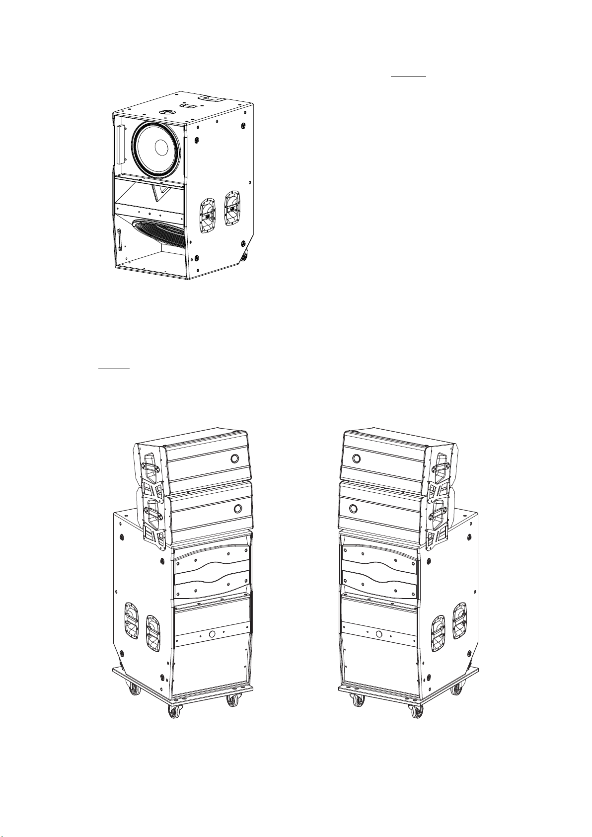
SF-1521A
– 15GNR mid-bass speaker
– 21UXN4 low frequency speaker
– DASnet™ remote monitoring and control
capable
– Companion mid-high system SF-20A (L/R)
The SF-1521A is a unique, powered hybrid
subwoofer system which is part of the SF-Monitor
system. It combines the hard-hitting and defined
performance of a 15" loudspeaker with the deep,
air-moving power of a 21". The SF-1521A employs
the 15GNR loudspeaker for mid-bass reproduction
up to 200 Hz. The extreme low end of the
system´s frequency range is handled by a single
21UXN4 loudspeaker ideal for demanding dance
club applications. A Class D two channel amplifier
developing 1700 Wcontinuos per channel provides
the power. The SF-1521A can also be deployed for
impressive low frequency reproduction in support
systems.
Note:
It’s allowed stacking up to 2 units on a SF-1521A, but the SF-20A (L / R) presets allow to work up to 4 units.
PL-SFMS
The PL-SFMS is an accessory dolly, it allows to move easy the system (see images below), so when units
are transported on the platform, precaution must be taken to avoid tipping, and prevent injuries.
Left SF-Monitor + PL-SFMS Right SF-Monitor + PL-SFMS
Manual del Usuario / SF series / User’s Manual
7
Page 8

CONFIGURATIONS
NOTE :
1-. On the SF-20A (L/R) select DJ Mode 2 Units and
High Pass filter SF-1521A.
2-. On the SF-1521A select DJ Mode (gain up
to the user) and Low Pass filter SF-20A (L/R).
3-. By proceeding this way the system is already
time aligned and no processor is needed.
LINK
2 x SF-20A L
D.J Mixer
2 x SF-20A R
LINK
POWER
SUPPLY
LINK LINK
LINK
POWER
SUPPLY
LINK LIN K
LINK LIN K
1 x SF-1521A
Configuration without DASnet
1 x SF-1521A
TM
LINK
D.J Mixer
L R
2 x SF-20A L
LINK LINK
Matrix 9X9
MAX.
20A/ OUT
AUDIO / DASNET OUT
OUT2OUT
1
OUT
3
PH.1 PH.2 PH.3
AUDIO IN
2
2
2
2
1
1
1
1
3
3
3
3
LINK 1&2 LINK 2&3 LINK 3&4 LINK 4&5 LINK 5&6 LINK 6&7 LINK 7&8 LINK 8&9
2
1
1
3
OUT
1
9xMCB 16A “C” 1pol.
1x RCD 40A 30mA 4pol.
2
3
OUT
2
OUT
3
PUSH
231
2
2
2
1
1
1
3
3
3
TERMINATION
RESISTOR
2
1
POWER
ON
3
OUT
OUT
1
2
OUT
3
L1
FI-Schalter
I
FI4030mA4pol.
L2
o
L3
2 x SF-20A R
LINKLINK
LINKLINK
Dasnet Rack 99
1 x SF-1521A
eCPK_5
Configuration with DASnet
8
Manual del Usuario / SF series / User’s Manual
TM
1 x SF-1521A
eCPK_5
Page 9

SPECIFICATIONS
Model
Nominal LF Power Amplifier 2 x 3400 W
SF-1521A
– 2 x 1700 W
peak
continuous
SF-20AL / SF-20AR
800 W (Class D)
Nominal HF Power Amplifier --- 400 W (Class D)
Input Type Balanced Differential Line Balanced Differential Line
Input Impedance Line: 20 kohms Line: 20 kohms
Sensitivity Line: 4.9 V (+16 dBu) Line: 4.9 V (+16dBu)
Frequency Range (-10 dB) 28 Hz -200 Hz 60 Hz -20 kHz
Horizontal Coverage (-6dB) --- 90º Nominal
Vertical Coverage --- Splay Dependent
Rated Maximum Peak SPL at 1 m
Transducers / Replacement Parts
(1)
141 dB 136 dB
LF1: 1 x 21UXN4 / GM 21UXN4 LF: 1 x 12AN4 / GM 12AN4
LF2: 1 x 15GNR / GM 15G HF: 1 x M-75N / GM M-75N
Enclosure Geometry Rectangular Trapezoidal 3,5º
Enclosure Material Birch Plywood Birch Plywood
Color : Cabinet
Color : Parts
(2)
(2)
Black / ISO-flex paint Black / ISO-flex paint
Red paint Red paint
Rigging System Splay Angles --- Integrated in box design
Audio INPUT: Female XLR Audio INPUT: Female XLR
Aduio LOOP THRU: Male XLR Aduio LOOP THRU: Male XLR
Connectors
Audio + Data INPUT: EtherCon Audio + Data INPUT: EtherCon
Audio + Data LOOP THRU: EtherCon Audio + Data LOOP THRU: EtherCon
AC INPUT: PowerCon TRUE1 NAC3FX AC INPUT: PowerCon TRUE1 NAC3FX
AC OUTPUT: PowerCon TRUE1 NAC3MX AC OUTPUT: PowerCon TRUE1 NAC3MX
AC Power Requirements
Dimensions (H x W x D)
(3)
8A, 115 V, 50 Hz/60 Hz 3.6A, 115 V, 50 Hz/60 Hz
4A, 230 V, 50 Hz/60 Hz 1.8A, 230 V, 50 Hz/60 Hz
106 x 61 x 75.3 cm 31 x 61 x 43 cm
(41.7 x 24 x 29.6 in) (12.2 x 24 x 16.9 in)
Weight 102 kg (224 lb) 28 kg (61.5 lb)
Accessories
PL-SFMS
TRD-6
(1)
Notes:
Maximum calculated Peak SPL based on sensitivity and RMS power handling.
(2)
Custom color schemes.
(3)
Measured data, providing one third of nominal power with Pink Noise input signal.
D.A.S. Audio S.A. continuously strives to enhance its products through investigation and development. All specifications are
subject to change without prior warning.
Manual del Usuario / SF series / User’s Manual
9
Page 10

LINE DRAWINGS
ALL DIMEN SIONS IN MILI METERS
SF-20ALSF-20ARSF-1521A
Bottom view
Front view
Rear viewLeft view
Left viewFront viewBottom view
Rear view
10
Rear viewLeft viewFront viewBottom view
Manual del Usuario / SF series / User’s Manual
Page 11

DESCRIPTION OF AMPLIFIERS
SOUND
20A
FO RCE
D.A.S. Audio, s.a. (Valencia), MADE IN SPAIN
DJ
Main
ID DASNET
mon
PA
11
1
2
IN OUT
3
4
NUMBER
SIGNAL/
OF UNITS
7
IDENTIFY/COMMS
4
LIMIT
SIGNAL INPUT
1
LOOP THRU
2
HIGH PASS
FILTER
8
OFF
160Hz
SF-1521A
HPF
PRESET
3
6
ON/PROTECT
5
NUMBER OF UNITS
9
UNIT NAME STAGE / VENUE
RISK OF ELECTRIC SHOCK
DO NOT OPEN
CAUTION
DO NOT EXPOSE THIS EQUIPMENT
TO RAIN OR MOISTURE
AC INPUT
100-230 V~ 50/60Hz 420W
HIGH PASS FILTER
MAX. 7@230V / 3@115V UNITS SF-20A
10
www.dasaudio.com
AC OUTPUT
SF-20A (L/R)
SOUND
FO RC E
D.A.S. Audio, s.a. (Valencia), MADE IN SPAIN
NOTES LOW PASS FILTER
9
UNIT NAME STAGE / VENUE
www.dasaudio.com
1521A
DJ
Main
ID DASNET
mon
PA
11
-2dB
0dB
IN OUT
+2dB
+4dB
SYSTEM
GAIN
IDENTIFY/COMMS
AC INPUT
920W
SIGNAL/
LIMIT
SIGNAL INPUT LOOP THRU
1
2
7
4
100-230V~ 50/60Hz
MAX. 2@230V/1@115V
10
5
AC OUTPUT
UNITS SF-1521A
LOW PASS
8
3
ON/PROTECT
RISK OF ELECTRIC SHOCK
DO NOT OPEN
CAUTION
DO NOT EXPOSE THIS EQUIPMENT
TO RAIN OR MOISTURE
125Hz
160Hz
SF-20A
LPF
PRESET
FILTER
6
SF-1521A
1) SIGNAL INPUT :
XLR type input signal connectors. As the LOOP THRU connector, they are balanced with the following
pin assignments:
1=GND (Ground).
2=(+) Non inverted input.
3=(-) Inverted input.
2) LOOP THRU :
XLR type output signal connector for connecting several units together and sending them all the same
input signal.
3) SIGNAL / LIMIT :
Two color LED which indicates that there is signal presence if it shines green or indicates amplifier
saturation and the amplifier limiter is activated, if it shines red.
4) IDENTIFY / COMMS :
Orange LED that shines flashing when we push IDENTIFY (to identify the unit) or blink faster if there is
communication with DASnet .
5) ON / PROTECT :
Two color LED indicates that the unit is ON if it shines green and protection if it shines red.
TM
Manual del Usuario / SF series / User’s Manual
11
Page 12

6) HPF PRESET [SF-20A (L/R)]:
This push button allows the “HIGH PASS FILTER” selection. The LED shining indicates the selected
value: OFF (60 Hz), 160 Hz or SF-1521A (200 Hz).
6) LPF PRESET [SF-1521A]:
This push button allows the “HIGH PASS FILTER” selection. The LED shining indicates the selected
value: 125 Hz, 160 Hz or SF-20A (200 Hz).
7) NUMBER OF UNITS [SF-20A (L/R)]:
This push button allows the selection of number of units from 1 to 4 units, according to the operating
modes: MAIN PA or DJ MONITOR. The LED shining indicates the selected value.
7) SYSTEM GAIN [SF-1521A]:
This push button allows the preset selection for the system gain from -2dB to +4dB, in 2dB steps,
according to the operating modes: MAIN PA or DJ MONITOR. The LED shining indicates the selected value.
8) IN/OUT :
Neutrik EtherCon connectors for audio+data input/output with DASnet . With the output connector we
TM
can interconnect several units.
9) Zone for user notes.
10) AC INPUT SELECT :
This switch actives, or not, the mains connector at the front side of the enclosure. When we use a
cardioid configuration, we should connect the mains at the front side of the turned enclosure for wires'
grouping. Select before connecting power to the unit.
11) AC INPUT :
Neutrik PowerCon TRUE1 mains connector. Only use this equipment with an appropriate mains
cord.
12) AC OUTPUT :
Neutrik PowerCon TRUE1 mains connector for connecting several units of LX-118A (please, see the
maximum value on the label).
13) ID DASNET :
Label with identification number for DASnet .
TM
ON / OFF
A sound system should be switched on sequentially. Switch on the self-powered units last in your sound
system (switch on the subwoofer before the mid-high system). Switch on the sound sources such as CD
players or turntables, then the mixer, then the processors, and finally the self-powered unit. If you have
several units, it is recommended that you switch them on sequentially one at a time.
Follow the inverse order when switching off, turning self-powered units off before any other element in the
sound system.
Disconnect the device by removing the mains connector from the mains socket. The mains connector
and mains socket must always be freely accessible and never covered or blocked in any way.
The models use a power cable equipped with a Neutrik PowerCon TRUE1 connector. Power can be
daisy chained via the TRUE1 output connector (see details on product label).
IMPORTANT: Do not disconnect the unit while in use.
Ensure that the device is disconnected from the mains by observing that the ON LED is turned off. Please
note that the ON LED can stay on for several seconds after the mains power has been disconnected.
Overload indicator
This device has a SIGNAL/LIMIT indicator. The
red light indicates the signal is excessive.
Overheating
This equipment does not normally overheat
during normal conditions of use. When overheating
occurs, the unit protects itself. You should then
The indicator should not be lit continuously.
This distorts the signal (quickly fatiguing your ears)
and may damage the speakers.
find out why and if necessary contact an
authorised dealer for technical assistance.
Normally it is enough just to let the unit cool
down after you have corrected the problem so that
Equalisation
the system functions properly again.
Low mains voltage
The unit does not need extreme settings of
equalisation to produce quality sound. Avoid high
levels of gain on the equalisers. Gain values above
+3 dB on a console’s EQ are not recommended.
If mains voltage falls below the shutdown
voltage for the unit, it will stop playing. When
acceptable levels are regained, the unit will switch
back on automatically.
The unit recognises the value of mains
automatically. The unit works from 80V to 260V
(both rms).
12
Manual del Usuario / SF series / User’s Manual
Page 13

Presets
Although some parameters such as number of units, gain, LPF and HPF can be selected by acting on the
switches of the amplifiers, it is more comfortable and more complete, to make the changes of the presets by
TM
DASnet , as we can observe in some examples below.
High Pass Filters (HPF)
This type of filter is implemented in the SF-20A
(L/R). There are three available settings: OFF
(cutoff at 60 Hz), cutoff at 160 Hz and filter suitable
for combined with SF-1521A (cutoff at 200 Hz). In
the curves below, you can appreciate the
difference.
1
2
3
Frequency response curves
(1) - OFF (60Hz)
(2) - 160Hz
(3) - SF-1521A (200Hz)
Low Pass Filters (LPF)
This type of filter is implemented in the SF1521A. There are three available settings: cutoff at
125 Hz, cutoff at 160 Hz and filter suitable for
combined with SF-20A (L/R) (cutoff at 200 Hz). In
the curves below, you can appreciate the
difference.
View of
DASnet
TM
2
3
1
Frequency response curves
(1) - 125Hz
(2) - 160Hz
(3) - SF-20A (200Hz)
Manual del Usuario / SF series / User’s Manual
View of
DASnet
TM
13
Page 14

Number of units and system gain
TM
Below, we can see the preset values for these parameters, as we can see them on .
DASnet
Presets as shown on
DASnet
TM
Examples and recommended presets
Then, we will see two examples to help us understand their combinations, with curves and as we will view
them on .
DASnet
TM
Example: 1x SF-20A (L/R) (1u DJ mode) + 1x SF-1521A (-2dB DJ mode)
SF-20A (L/R)
with 13º
TM
Example: 2x SF-20A (L/R) (2u PA mode ; gain -6dB on ) + 1x SF-1521A (-2dB DJ mode)
DASnet
14
all SF-20A (L/R)
with 3.5º
Manual del Usuario / SF series / User’s Manual
Page 15

Troubleshooting
PROBLEM
CAUSE
SOLUTION
No sound from the unit. The
SIGNAL LED does not light up.
Full power cannot be obtained. The
LIMIT LED never lights up.
Sound is distorted. The LIMIT LED is
not on, or only lights up occasionally.
Sound is distorted and very loud
and LIMIT LED lights up.
Hum or buzz when a mixer is
connected to the unit.
Hum or buzz when using lighting
controls in the same building.
1 – The signal source is sending no
signal.
2 – Defective cable.
1 - The signal source does not have
a hot enough output.
2 - If the connections are correct, It
might be overheating
1 - The mixer or signal source is
distorting.
1 - The system is overloaded and
has reached maximum power.
1.– The console probably has unbalanced outputs. You may be using
an incorrect un-balanced to
balanced cable.
2.– The mixer and the powered
speaker are not plugged into the
same mains outlet.
3.– The audio signal cable is too
long or too close to an AC cable.
4 - DASnet ecP_xx cable is
defective.
5 - Error in DASnet Patch panel 485
net connection.
1.– The audio signal cable is too
long or too close to the lighting
cable.
2.– In a sound system with threephase AC, the lighting equipment
and the UNIT are connected to the
same phase.
1 – Check that the mixer or sound
source is sending signal to the UNIT.
2 – Check that the cable from the
sound source to the UNIT is
connected correctly. Replace the
cable if defective.
1 - If using a mixer, use the
balanced output if available. Use a
professional mixer with a hotter
output.
2 - Try to cool the unit turning down
the master of the mixer.
1 - Turn mixer channel gains down.
Check that none of your signal
sources are distorting.
1 - Turn down the mixer's output.
1.– Read the appendix of this
manual to make a correct unbalanced to balanced cable.
2.– Connect the mixer and the unit
to the same mains outlet.
3.– Use a cable that is as short as
possible and/or move the audio
signal cable away from the mains
cables.
4 - Check that there aren´t pins
crossed in CAT7 cable. Possible
short between audio par and
DASnet signal.
5 - Make sure that Audio INPUT is
not connected in DASnet INPUT and
vice versa.
1.– Move the audio signal cable
away from lighting cables. Try to find
out at what point the noise is leaking
into the system.
2.– Connect the sound system to a
different phase than the lights. You
may need the help of an electrician.
The ON LED does not light up when
the mains connector is connected
and the unit is switched to ON.
1.– Bad or loose AC connection to
the UNIT or the mains outlet.
2 – Faulty AC cable.
3 - Internal fuse blown
Manual del Usuario / SF series / User’s Manual
1.– Check your connections.
2.– Check the cables, connectors
and AC power with a suitable mains
tester.
3 - Replace the fuse for another of
the same size and type.
15
Page 16

INSTALLATION AND ACCESSORIES
In this section we will see how to stack the SF-20A (L / R) on the SF-1521A. In addition, with the help of two
metal plates, JP-20, included in each SF-20A (L / R), we will see how to angle the SF-20A (L / R) according to the
desired coverage, with examples .
Moreover, the accessory PL-SFMS allows us to safety move the SF-Monitor system.
In the following images we see that the sides of JP-20. Silkscreen’s indications help us for the correct
assembly and to assign the angles of the boxes.
LEF T SIDE
RIG HT SIDE
JP-20
First, we take the SF-1521A, and if you then want to move the system, we put it on the PL-SFMS as shown
below.
Now, with or without PL-SFMS, we will remove the screws indicated so you can mount the JP-20.
PL-SFMS
16
SF-1521A on PL-SFMS
SF-1521A
Manual del Usuario / SF series / User’s Manual
Page 17

Now, we will screw each JP-20 on the corresponding side, considering the angle assigned to the box, but
do not tighten completely. Allowing you to place easily the SF-20A (L/R) on SF-1521A.
Once the SF-20A (L/R) is located above of SF-1521A, you should tighten the screws into the appropriate
holes at the desired angle.
If the system has only a SF-20A (L/R), then the system is already mounted.
But, to stack a second SF-20A (L/R) on top, first you proceed to remove the screws from the SF-20A (L/R)
to mount another JP-20.
As in the previous case, each JP-20 piece should be screwed in its corresponding side considering the
angle assigned to the box without fully tightening, to place easily the upper SF-20A (L/R).
Once the SF-20A (L/R) is located above, tighten the screws into the appropriate holes at the desired
angle.
So, the SF-Monitor system (left or right) is mounted, according the angles to the desired coverage.
Manual del Usuario / SF series / User’s Manual
17
Page 18

Let's look at some examples of these coverages for the system SF-Monitor (right or left), according to the
selected angles.
If we had only one SF-20A (L/R), we would have the following coverage for the recommended angle: 13º.
Note: The red dots in the JP-20 indicate the proper position for the screws in each case.
2m
ANG. 13º
(recommended)
0º
0º
3.5º
3.5º
7º
7º
SF1521A
SF1521A
SF1521A
SF1521A
13º
13º
SF20A
SF20A
FRONT
FRONT
2m
1.65m
1.65m
1.5m
1.5m
1m
1m
0.5m
0.5m
Ground stacked
0.5m 1m 1.5m 2m 2.5m 3m
0.5m 1m 1.5m 2m 2.5m 3m
ANG. 13º
(recommended)
0º
3.5º
7º
SF1521A
SF1521A
13º
SF20A
FRONT
2m
2m
1.65m
1.65m
1.5m
1.5m
1m
1m
0.5m
0.5m
On a PL-SFMS
0.5m 1m 1.5m 2m 2.5m 3m
0.5m 1m 1.5m 2m 2.5m 3m
As can be seen, our coverage varies if the system is mounted on platform.
Therefore, below we distinguish these two options in the examples for the case of having two SF-20A
(L/R) in our system, indicating the position of the screws as before in the images of the JP-20.
Ground stacked
ANG. 0º (upper) y 0º (lower)
13º
SF1521A
SF1521A
SF1521A
SF1521A
13º
SF20A
SF20A
FRONT
FRONT
13º
13º
SF20A
SF20A
FRONT
FRONT
0.5m 1m 1.5m 2m 2.5m 3m
0.5m 1m 1.5m 2m 2.5m 3m
0º
0º
3.5º
3.5º
7º
7º
SF1521A
SF1521A
0º
0º
3.5º
3.5º
7º
7º
SF1521A
SF1521A
2m
2m
1.65m
1.65m
1.5m
1.5m
1m
1m
0.5m
0.5m
18
Manual del Usuario / SF series / User’s Manual
Page 19

Ground stacked (cont’d)
ANG. 3.5º (lower) y 0º (upper)
13º
SF1521A
SF1521A
SF1521A
SF1521A
13º
SF20A
SF20A
FRONT
FRONT
13º
13º
SF20A
SF20A
FRONT
FRONT
0º
0º
3.5º
3.5º
7º
7º
SF1521A
SF1521A
0º
0º
3.5º
3.5º
7º
7º
SF1521A
SF1521A
ANG. 3.5º (upper) y 3.5º (lower)
(recommended)
13º
SF1521A
SF1521A
13º
SF20A
SF20A
FRONT
FRONT
0º
0º
3.5º
3.5º
7º
7º
SF1521A
SF1521A
0.5m 1m 1.5m 2m 2.5m 3m
0.5m 1m 1.5m 2m 2.5m 3m
2m
2m
1.65m
1.65m
1.5m
1.5m
1m
1m
0.5m
0.5m
2m
2m
1.65m
1.65m
1.5m
1.5m
13º
SF1521A
SF1521A
13º
SF20A
SF20A
FRONT
FRONT
0º
0º
3.5º
3.5º
7º
7º
SF1521A
SF1521A
ANG. 3.5º (lower) y 7º (upper)
13º
SF1521A
SF1521A
SF1521A
SF1521A
13º
SF20A
SF20A
FRONT
FRONT
13º
13º
SF20A
SF20A
FRONT
FRONT
0º
0º
3.5º
3.5º
7º
7º
SF1521A
SF1521A
0º
0º
3.5º
3.5º
7º
7º
SF1521A
SF1521A
0.5m 1m 1.5m 2m 2.5m 3m
0.5m 1m 1.5m 2m 2.5m 3m
0.5m 1m 1.5m 2m 2.5m 3m
0.5m 1m 1.5m 2m 2.5m 3m
1m
1m
0.5m
0.5m
2m
2m
1.65m
1.65m
1.5m
1.5m
1m
1m
0.5m
0.5m
We recommend using 3.5º for two SF-20A (L/R) in this system configuration.
Now we will see examples for systems on platform.
Manual del Usuario / SF series / User’s Manual
19
Page 20

On a PL-SFMS
ANG. 0º (lower) y 0º (upper)
13º
SF1521A
SF1521A
SF1521A
SF1521A
13º
SF20A
SF20A
FRONT
FRONT
13º
13º
SF20A
SF20A
FRONT
FRONT
0º
0º
3.5º
3.5º
7º
7º
SF1521A
SF1521A
0º
0º
3.5º
3.5º
7º
7º
SF1521A
SF1521A
ANG. 3.5º (lower) y 0º (upper)
13º
SF1521A
SF1521A
SF1521A
SF1521A
13º
SF20A
SF20A
FRONT
FRONT
13º
13º
SF20A
SF20A
FRONT
FRONT
0º
0º
3.5º
3.5º
7º
7º
SF1521A
SF1521A
0º
0º
3.5º
3.5º
7º
7º
SF1521A
SF1521A
0.5m 1m 1.5m 2m 2.5m 3m
0.5m 1m 1.5m 2m 2.5m 3m
0.5m 1m 1.5m 2m 2.5m 3m
0.5m 1m 1.5m 2m 2.5m 3m
2m
2m
1.65m
1.65m
1.5m
1.5m
1m
1m
0.5m
0.5m
2m
2m
1.65m
1.65m
1.5m
1.5m
1m
1m
0.5m
0.5m
ANG. 3.5º (upper) y 3.5º (lower)
(recommended)
13º
SF1521A
SF1521A
SF1521A
SF1521A
13º
SF20A
SF20A
FRONT
FRONT
13º
13º
SF20A
SF20A
FRONT
FRONT
0º
0º
3.5º
3.5º
7º
7º
SF1521A
SF1521A
0º
0º
3.5º
3.5º
7º
7º
SF1521A
SF1521A
ANG. 3.5º (lower) y 7º (upper)
13º
SF1521A
SF1521A
SF1521A
SF1521A
13º
SF20A
SF20A
FRONT
FRONT
13º
13º
SF20A
SF20A
FRONT
FRONT
0º
0º
3.5º
3.5º
7º
7º
SF1521A
SF1521A
0º
0º
3.5º
3.5º
7º
7º
SF1521A
SF1521A
0.5m 1m 1.5m 2m 2.5m 3m
0.5m 1m 1.5m 2m 2.5m 3m
0.5m 1m 1.5m 2m 2.5m 3m
0.5m 1m 1.5m 2m 2.5m 3m
2m
2m
1.65m
1.65m
1.5m
1.5m
1m
1m
0.5m
0.5m
2m
2m
1.65m
1.65m
1.5m
1.5m
1m
1m
0.5m
0.5m
20
Manual del Usuario / SF series / User’s Manual
Page 21

ANNEX I : Line connections: unbalanced and balanced
There are two basic ways to transport an audio signal with microphone or line level:
Unbalanced line: Utilising a two conductor cable, it transports the signal as the voltage between them.
Electromagnetic interference can get added to the signal as undesired noise. Connectors that carry
unbalanced signals have two pins, such as RCA (Phono) and ¼” (6.35mm, often referred to as jack) mono. 3
pin connector such as XLR (Cannon) may also carry unbalanced signals if one of the pins is unused.
Balanced line: Utilising a three conductor cable, one of them acts as a shield against electromagnetic
noise and is the ground conductor. The other two have the same voltage with respect to the ground
conductor but with opposite signs. The noise that cannot be rejected by the shield affects both signal
conductors in the same way. At the device’s input the two signals get summed with opposite sign, so that
noise is cancelled out while the programme signal doubles in level. Most professional audio devices use
balanced inputs and outputs. Connectors that can carry balanced signal have three pins, such as XLR
(Cannon) and ¼” (6.35mm) stereo.
The graphs that follow show the recommended connection with different types of connectors to balanced
processor or amplifier inputs. The connectors on the left-hand side come from a signal source, and the ones
on the right hand side go to the inputs of the processor or amplifier. Note that on the unbalanced connectors
on the left-hand side, two terminals are joined inside the connector. If hum occurs with balanced to balanced
connections, try disconnecting the sleeve (ground) on the input connector. Note that the illustrations show
what should be connected to what, but that pin locations on an actual XLR connector are different. Also, pin
2 hot is assumed on XLR connectors.
Manual del Usuario / SF series / User’s Manual
21
Page 22

ANNEX II : DASnet cables
With each system, cabling and patch panels are provided. It is very important to use the
system with the intended cables to prevent electromagnetic interferences between the
analog audio signal, the DASnet data and the power. Be sure to check the specifications
provided by the cable manufacturer. It is also especially important when installing
connectors yourself, to note that when termination is not accurate, a cable will be unable to
achieve its maximum performance and could have interferences.
There are 4 different types of cables.
- The main feeds which include power and a STP, CAT7 cable. These cables are
named eCP_xx (xx refers to cable length).
- The links between cabinets (aero40A/Convert15A/LX-218CAnet), which are STP
CAT7 cables. Cable code eC_09
- Power Links between cabinets.Cable code Plink1_09
- Links for RoadNet series. Power+STP CAT7. eCPk_1/eCPk_5
Important
The main feed cable eCP_xx has the following structure:
Jacket
STP CAT 7 cable with Aluminium Shield for
each individual pair and a main aluminium
AL Shield
Shield.
The main Shield has to be soldered to the
etherCon housing.
The eC_09 cable is a CAT5e cable with
global Aluminium Shield.
ecP_xx: Power cable 3x2.5mm + CAT7 4x (2 x 0.14mm )
2 2
The pin out of the EtherCon to XLR is the following on the eCP cables:
etherCon XLR
1 Orange-White Audio+ 2
2 Orange Audio- 3
3 Green-White Audio Earth 1
4 Blue
5 Blue-White
6 Green Data Earth 1
7 Brown-White Data- (A) 3
8 Brown Data+ (B) 2
Jacket
22
Manual del Usuario / SF series / User’s Manual
Page 23

www.dasaudio.com
UM_SF_01_ES
D.A.S. AUDIO, S.A.
C/. Islas Baleares, 24
46988 Fuente del Jarro
Valencia, SPAIN
Tel. +34 96 134 0860
D.A.S. AUDIO OF AMERICA, INC.
6900 NW 52th Street
Miami, FL. 33166 - U.S.A.
TOLL FREE: 1 888 DAS 4 USA
D.A.S. AUDIO ASIA PTE. LTD.
3 Temasek Avenue, Centennial Tower #34-36
Singapore 039190
Tel. +65 6549 7760
 Loading...