

Page 1

Page 2

¡ATENCIÓN!
El DSP-48 ocupa un espacio de rack estándar de 1 Unidad (19”). En la instalación debe dejar una distancia
mínima de 4” para los conectores del panel trasero. El montaje debe dejar suficiente espacio alrededor del
aparato para que permita una correcta ventilación. No se debe montar sobre otros aparatos que sean una
importante fuente de calor, como amplificadores, etc. para evitar el sobrecalentamiento.
El DSP-48 se suministra con un cable de alimentación independiente al conector IEC posterior. Este cable
cumple con las normas se seguridad eléctrica internacionales.
El cable suministrado dispone de tres patillas de conexión, una de ellas es la de tierra. Es muy importante
que el aparato siempre esté conectado a una instalación eléctrica segura con toma de tierra.
En caso de avería el aparato debe ser reparado por personal cualificado de uno de nuestros servicios técnicos
autorizados. El técnico deberá estar conectado a tierra , ya que las cargas
electrostáticas pueden afectar al funcionamiento.
NOTA:
instalado es el correcto.
Antes de conectarlo hay que comprobar la tensión de la red eléctrica y comprobar que el fusible
para manipular el aparato
ATTENTION!
The DSP-48 fits into a standard 19" rack unit of space (1 3/4"). Allow at least an additional 4" depth for the
connectors on the back panel. Be sure that there is enough air space around the unit for cooling and ventilation.
DO NOT place the DSP-48 on high temperature devices like power amplifiers etc. to avoid overheating.
Using a main cable and a standard IEC receptacle makes the main connection of the DSP-48. It meets all of the
international safety certification requirements.
Please make sure that all units have a proper ground connection. For your own safety, do not remove the ground
connection within the unit or at the supply, or fail to make this connection at all.
This machine is only intended for qualified personnel to operate & install. Do not attempt to repair and service
yourself but referred to qualified technical service personnel. The user must have sufficient electrical contact
to earth. Electrostatic charges might affect the operation of the DSP-48.
NOTICE: If the fuse needs to be replaced, please pay attention to correct type and ratings.
Page 3
CARACTERíSTICAS
Procesador digital de señal de 24 bits.
4 entradas/ 8 salidas con varios tipos de crossover para dar gran flexibilidad de configuración.
Filtros de tipo Butterworth, Linkwitz-Riley o Bessel, con pendientes de cruce de 12 dB, 18 dB,
24 dB y 48 dB por octava.
6 puntos de EQ en cada entrada y 4 puntos de EQ en cada salida.
Tipos de ecualización: Paramétrica, L-Shelf y H-Shelf.
Ecualizaciones paramétricas en toda la banda pasante, con un rango por octava desde 1/64 hasta 4.0.
Retardos (delay) de hasta 682.52 ms en cada entrada y 21.31ms en cada salida.
Control de polaridad en cada salida.
En cada salida se puede ajustar el umbral, el limitador, el ratio, el tiempo de ataque y el tiempo de
relajación para configuraciones personalizadas.
Conexión USB para control vía PC.
Display LCD retro-iluminado de 2X20.
Indicadores de niveles de funcionamiento en frontal, mediante barras de leds para cada entrada
y cada salida.
Alimentación desde 90V hasta 250V.
2
Page 4

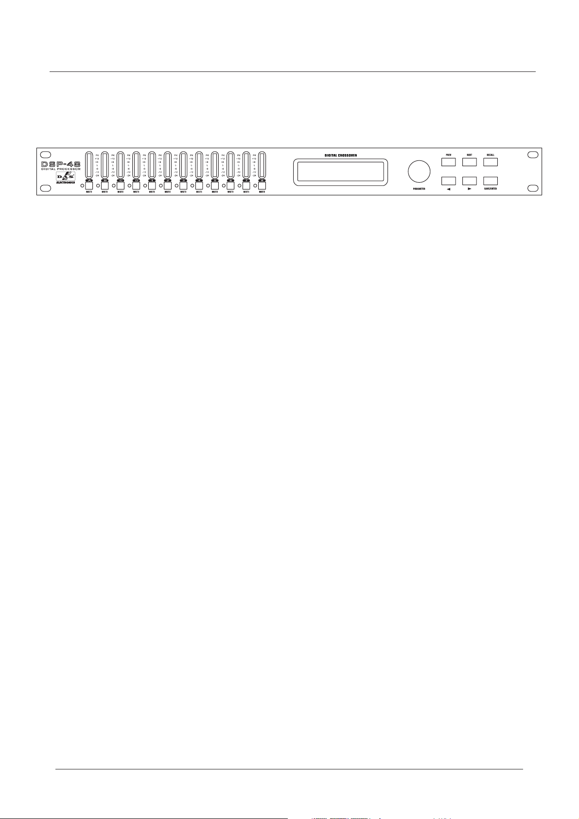
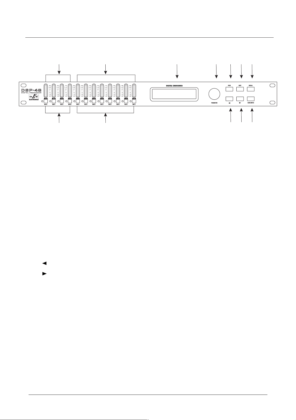
PANEL FRONTAL
12
8
1 . Barra de leds de 7 segmentos para indicador nivel de entrada.
2 . Barra de leds de 7 segmentos para indicador nivel de salida
3 . Pantalla LCD indicadora de todos los parámetros y funciones
4.
Pulsador / giratorio (PARAMETER) para acceso a menú de parámetros y funciones.
9
3
。
.
4
56
10
7
11 12
5 . PREV: Tecla para desplazamiento de las opciones del sub-menú.
Cambio de carácteres en la función de asignar nombre a programas, etc.
6 . NEXT: Tecla para desplazamiento de las opciones del sub-menú.
Cambio de carácteres en la función de asignar nombre a programas, etc.
RECALL:
7 . Rellamada de un programa y salida del menú.
8 . Input MUTE
9 . Output MUTE:
10 . Botón: Cambia de opción y cambia el valor del parámetro.
11 . Botón: Cambia de opción y cambia el valor del parámetro.
12 . SAVE/ENTER: Guarda el programa y confirma la opción.
: El led rojo se ilumina cuando la entrada se encuentra silenciada.
El led rojo se ilumina cuando la salida se encuentra silenciada.
3
Page 5

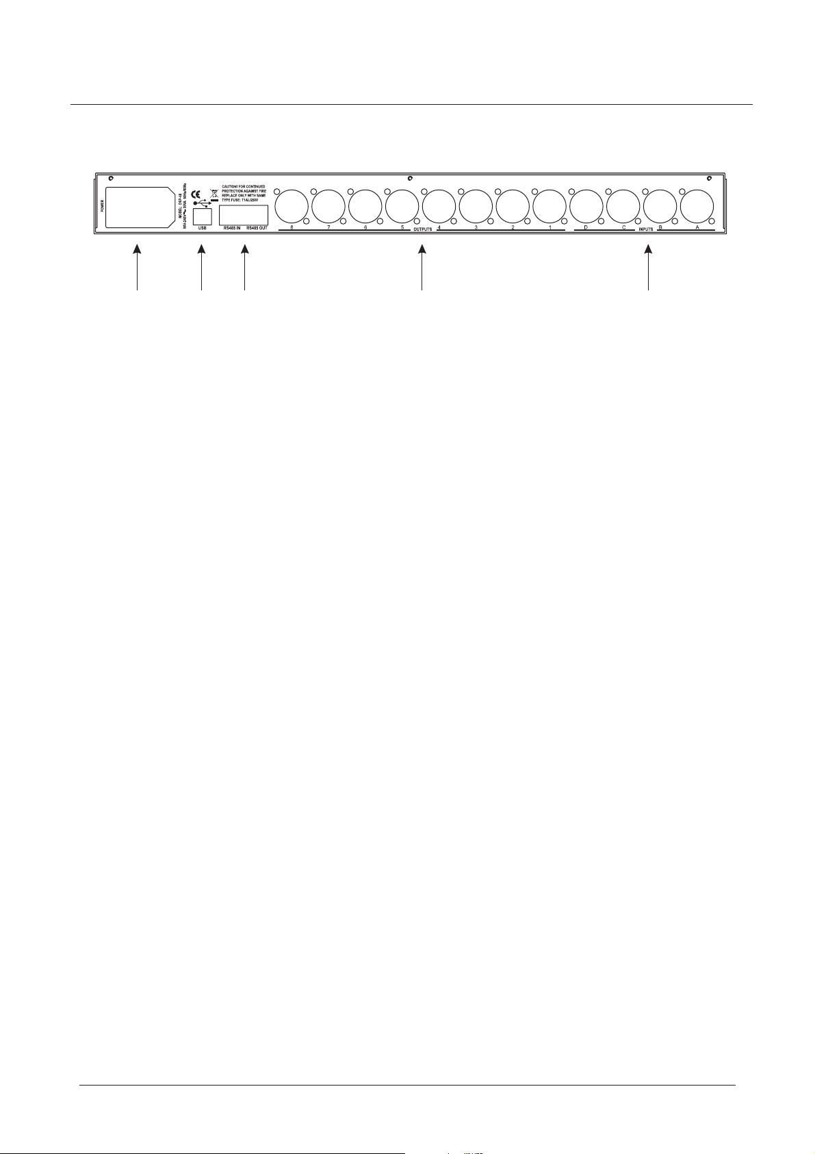
PANEL TRASERO
12
1 Alimentación.
2 Conector USB para control vía PC.
3 Interface RS485.
4 Ocho conectores XLR macho para salida de señal.
5 Cuatro conectores XLR hembra para entrada de señal.
3
4
5
4
Page 6

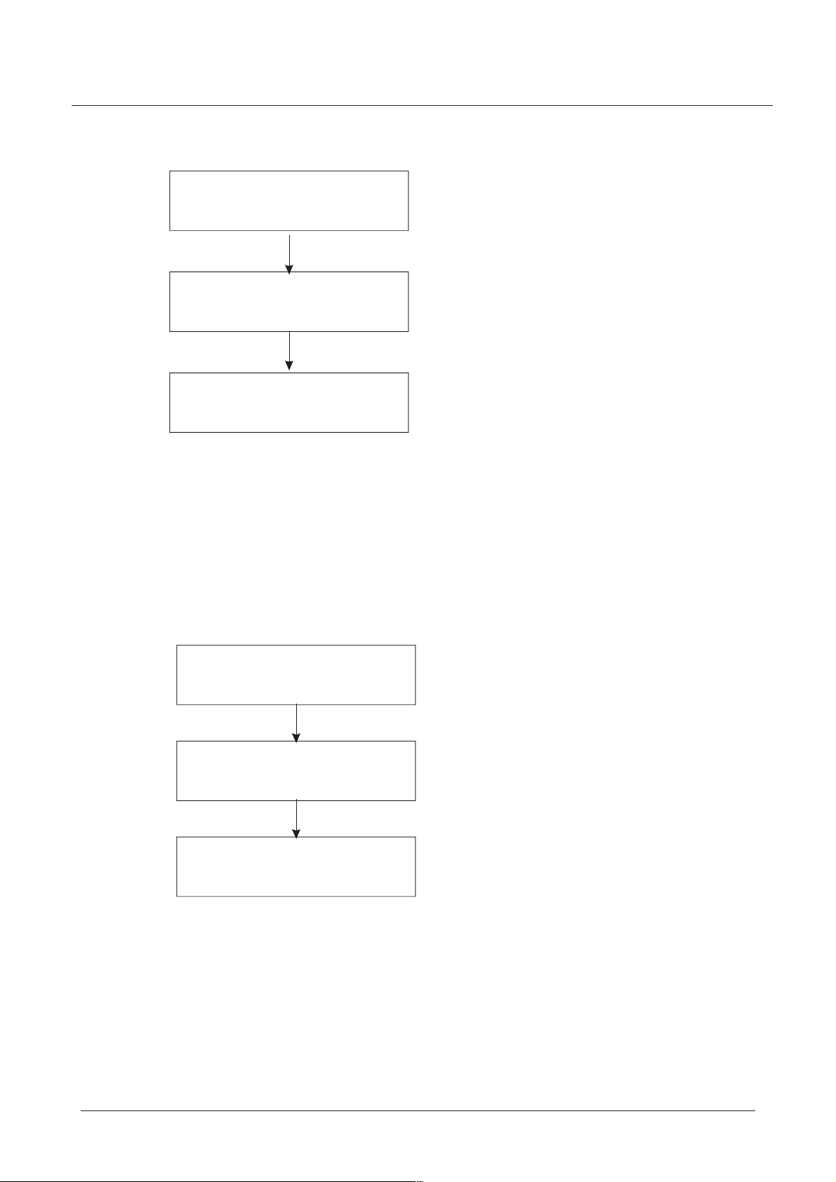
OPERACIONES
1.Ajuste de parámetros en el canal de entrada.
IN:A
Gain = 0.0dB
IN:A DELAY 145.87ms
50.24m 164.83ft
INPUT GAIN /Ganancia de entrada.
El rango de ganancia es de -40 dB a +12dB. En pasos de 0.1dB.
Use el botón PARAMETER, o para cambiar el valor preestablecido.
El botón giratorio PARAMETER cambia el valor en pasos de 0.1 dB.
Si utilizamos los pulsadores o cambian en pasos de 5.0 dB.
En el frontal hay un botón MUTE para silenciar rápidamente.
PulseNEXTparaentrarenelsub-menúinputdelay.
Pulse PREV para entrar en el sub-menú copy input data.
Pulse el botón giratorio PARAMETER para seleccionar otro canal.
INPUT DELAY /Retardo en la entrada
Cada una de las entradas dispone de un retardo de hasta 682.52ms,
en pasos de 21 s, expresado en las medidas más habituales;
milisegundos (ms), metros (m) y pies (ft).
El botón giratorio PARAMETER cambia el valor en pasos de 21 s.
Los pulsadores o cambian en pasos de 5.20 ms.
µ
µ
IN:A EQ ON F:1-PEQ
→
0.0dB 1000Hz 1.00
PulseNEXTparaentrarenelsub-menuinputEQ.
Pulse PREV para entrar en el sub-menu input gain.
Pulse el botón giratorio PARAMETER para seleccionar otro canal.
INPUTEQ/Ecualizaciónalaentrada
Cada canal de entrada dispone de 6 puntos de ecualización, con
un rango de ganacia ajustable entre -30 dB y +15 dB. Se puede
seleccionar los siguientes tipos de ecualización:
- PEQ. Ecualización Paramétrica. Rango de frecuencias desde
19.7 Hz a 20 kHz, ajustable entre 0.016 Oct a 4.000 Oct.
- LS1. Low-Shelf 6 dB. Rango de frecuencias desde 19.7 Hza2kHz.
- LS2. Low-Shelf 12dB. Rango de frecuencias desde 19.7 Hza2kHz.
- HS1. High-Shelf 6dB. Rango de frecuencias desde 3886 Hz a 21.9 kHz.
- Hs2. High-Shelf 12 dB. Rango de frecuencias desde 3886 Hz a 21.9 kHz.
Mediante botón giratorio PARAMETER podemos ajustar estas opciones.
Pulse NEXT para entrar en el sub-menu copy input data.
PulsePREVparaentrarenelsub-menuinputDelay.
Los pulsadores o cambian las opciones: on-off, tipo de EQ, filtros,
ganancia, frecuencia y ancho de banda.
Pulse el botón giratorio PARAMETER para seleccionar otro canal.
5
Page 7

OPERACIONES
Copy Input A
to Input: B
2 Ajuste de parámetros en el canal de salida..
Op1 Gain 0.0dB
Phase:[+] Source:A
COPY INPUT DATA / Copiar datos de entrada
Con el botón giratorio PARAMETER seleccionamos el canal en el que
queremos copiar los ajustes.
Pulse NEXT para acceder al sub-menú input gain.
Pulse PREV para acceder al sub-menú input EQ .
Presione PARAMETER para cambiar de canal.
OUTPUT GAIN / Ganancia de salida
El rango de ganancia en la salida es de -40 dB +12 dB en pasos
de 0.1 dB El indicador (+) ó (-) nos muestra el estado de la fase
Cada una de las salidas puede asignarse a cualquiera de las entradas,
a la suma de A+B,C+D, A+B+C+Doaninguna
En el frontal hay un botón MUTE para silenciar rápidamente
Pulse NEXT para acceder al sub-menú output delay.
Pulse PREV para acceder al sub-menú copy output data.
Pulse o para cambiar la ganancia, fase, fuente de entrada, etc.
..
,
.
Op1 DELAY 16.10ms
5.54m 18.19ft
Op1 EQ ON F:1-PEQ
→
0.0dB 1000Hz 1.00
Presione el botón giratorio PARAMETER para acceder al siguiente canal.
OUT DELAY / Retardo en la salida
Cada canal de salida dispone de un retardo de hasta 21.31 ms, en
pasos de 21 s. Expresado en milisegundos (ms), metros (m) y pies (ft).
Para ajustar estos retardos podemos utilizar el botón PARAMETER
(en pasos de 21 s) o los controles o (en pasos de 5.20 ms)
Pulse NEXT para acceder al sub-menú output EQ .
Pulse PREV para acceder al sub-menú output gain.
Presione PARAMETER para seleccionar el siguiente canal.
OUTPUT EQ / Ecualización a la salida
En cada canal disponemos de 4 posiciones de ecualización:
- PEQ. Ecualización Paramétrica. Rango de frecuencias desde
19.7 Hz a 20 kHz, ajustable entre 0.016 Oct a 4.000 Oct.
- LS1. Low-Shelf 6 dB. Rango de frecuencias desde 19.7 Hza2kHz.
µ
µ
- LS2. Low-Shelf 12dB. Rango de frecuencias desde 19.7 Hza2kHz.
- HS1. High-Shelf 6dB. Rango de frecuencias desde 3886 Hz a 21.9 kHz.
- Hs2. High-Shelf 12 dB. Rango de frecuencias desde 3886 Hz a 21.9 kHz.
6
Page 8

OPERA ONCI ES
Mediante botón giratorio PARAMETER podemos ajustar estas opciones.
Pulse NEXT para entrar en el sub-menú output high-pass.
PulsePREVparaentrarenelsub-menúoutputdelay.
Los pulsadores o cambian las opciones: ganancia, fase, fuente
de entrada y otras opciones.
Pulse el botón giratorio PARAMETER para acceder al siguiente canal.
Op1 HighPassFilter
→
19.7Hz 24dB Linkwitz
Op1 LowPassFilter
→
16k0Hz 24dB Linkwitz
OUTPUT HIGH-PASS FILTER / Salida filtro paso alto
El rango de frecuencia de paso del filtro va desde 19.7 Hz hasta 21.9 kHz.
Tiposdefiltros:
.
Butterworth: 12, 18, 24 y 48 dB/ Octava.
Bessel: 12, 18, 24 y 48 dB/ Octava.
Linkwitz: 12, 24 y 48 dB/ Octava.
Mediante el botón giratorio PARAMETER ajustaremos el valor deseado.
Pulse NEXT para acceder al sub-menú output low-pass.
Pulse PREV para acceder al sub-menú output EQ
Pulse o para cambiar la frecuencia,pendiente, etc.
Presione el botón giratorio PARAMETER para acceder al siguiente canal.
OUTPUT LOW PASS FILTER / Salida filtro paso bajo
El rango de frecuencia desde 19.7 Hz hasta 21.9 kHz, OFF.
Tiposdefiltro:
Butterworth: 12, 18, 24 y 48 dB/ Octava.
Bessel: 12, 18, 24 y 48 dB/ Octava.
Op1 LIMITER 0dBu
→
Inf A.5ms R100ms
7
Linkwitz: 12, 24 y 48 dB/ Octava.
Mediante el botón giratorio PARAMETER ajustaremos el valor deseado.
Pulse NEXT para acceder al sub-menú output low-pass.
Pulse PREV para acceder al sub-menú output EQ
Pulse o para cambiar la frecuencia,pendiente, etc.
Presione el botón giratorio PARAMETER para acceder al siguiente canal.
OUTPUT LIMITER / Limitador de salida
El limitador es ajustable desde -20dBu hasta +20dBu, en pasos de 1dBu.
Las posibles relaciones de compresión del limitador son: 1.2:1,1.5:1,
2:1,3:1,4:1,6:1,10:1, 20:1 e infinito.
El tiempo de ataque puede ser 0.5ms,1ms, 2ms, 5ms, 10ms, 20ms o 50ms.
El tiempo de relajación puede ser 10ms, 20ms, 50ms,100ms, 200ms,
500ms o 1sec.
Page 9

OPERA IONCES
Mediante el botón giratorio PARAMETER ajustaremos el valor deseado.
Pulse NEXT para acceder al sub-menú copy output data.
Pulse PREV para acceder al sub-menú output low-pass.
Pulse o para ajustar opciones del limitador, umbral, ratio,
tiempo de ataque y tiempo de relajación.
Presione el botón giratorio PARAMETER para acceder al siguiente canal.
Copy Output 1
to Output:2
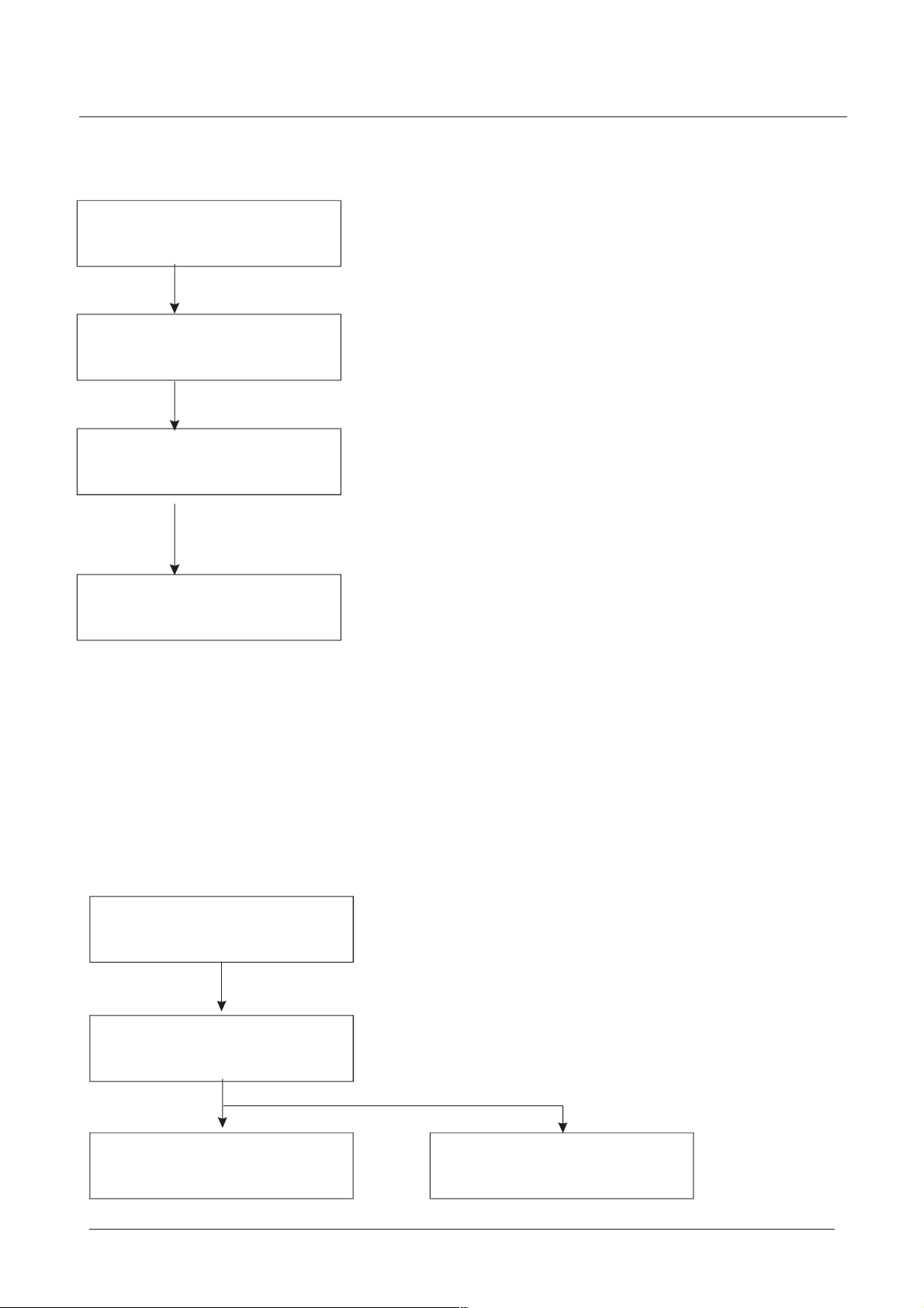
3 Operaciones con el menú principal.
MAIN MENU:*...
PROGRAM
Pulse SAVE/ENTER
PROGRAM
Pulse RECALL
Pulse PREV
Pulse NEXT
Pulse PREV
COPYOUTPUTDATA/Copiardatosdesalida
Seleccionar mediante el botón giratorio PARAMETER el canal deseado.
Pulse NEXT para acceder al sub-menú output gain.
Pulse PREV para acceder al sub-menú output EQ .
Presione el botón giratorio PARAMETER para acceder al siguiente canal.
MAIN MENU:*...
SECURITY
Pulse PREV
Pulse NEXT
MAIN MENU:*...
DUMP PROGRAM
Pulse NEXT
MAIN MENU *..
Pulse PREV
:.
RECEIVE DUMP
PROGRAM
Pulse PREV
PROGRAM
Load preset
Pulse SAVE/ENTER Pulse SAVE/ENTER Pulse SAVE/ENTER
Pulse NEXT
Load a program
4. Manejo del programa
El manejo del programa incluye los siguientes sub-menús:
4.1 Load preset mode / cargar configuraciones
Las distintas configuraciones pueden verse en el apéndice.
Program
Load Preset
Pulse SAVE/ENTER para cargar un preset.
LOAD PRESET
1:4X2-WAYCrossover
Gire el botón PARAMETER para elegir un preset, presione SAVE/ENTER
para cargar un preset.
LOADING PRESET
1:4X2-WAYCrossover
Pulse NEXT
Store a program
8
Page 10

OPERA IONCES
4.2 Loading program / cargar programa
Program
Load a program
Pulse SAVE/ENTER para acceder a la operación de cargar un programa.
LOAD PROGRAM: 1
4X2-WAYCrossover
Gire el botón PARAMETER para cambiar el nombre del programa,
presione SAVE/ENTER para cargar un programa.
LOADING PROGRAM
4X2-WAYCrossover
4.3 Storing program / almacenar programa
Se puede almacenar dentro de un programa todos los parámetros de ganancia de entrada, retardo
de entrada, ecualización de entrada, ganancia de salida, retardo de salida, ecualización de salida,
limitación de salida y fase de salida.
El nombre de un programa tiene un máximo de 20 carácteres.
Se puede almacenar 30 programas como máximo.
Program
Store a program
P.ulse SAVE/ENTER para acceder al sub -menú de almacenar un programa
STORE PROGRAM:1
4*2WAYCROSSOVER
Pulse SAVE/ENTER para almacenar un programa.
Cuando los dos puntos parpadean, gire el botón PARAMETER para
elegir el número del programa, pulse PREV y NEXT para cambiar la
posición del carácter, gire PARAMETER para elegir la letra.
STORING PROGRAM
4*2WAYCROSSOVER
9
Page 11

5. Menú de seguridad
OPERA IONCES
5.1 Bloqueo
MAIN MENU:.*....
SECURITY
Pulse SAVE/ENTER para acceder al
sub-menú de seguridad.
Lock Type
1:Modify
Gire PARAMETER para ajustar el tipo,
pulse SAVE/ENTER para fijarlo.
Set Password
[_ ]
Gire PARAMETER para cambiar las letras,
pulse PREV o NEXT para cambiar la
posición de la letra, pulse SAVE/ENTER
para guardar la contraseña.
LOCKING SYSTEM
Hay cuatro tipos de bloqueo:
1: Modify / Modificar
Los parámetros pueden verse pero no cambiarse. Mute activo.
2: Modify View / Modificar y ver
Los parámetros no pueden verse o cambiarse. Mute activo.
3: Modify Mute / Modicar y mute
Los parámetros pueden verse. Cambios y mute inactivos.
4: Everything /Todo
Todo esta bloqueado.
Use PARAMETER para elegir el tipo de bloqueado.
Pulse SAVE/ENTER para acceder a la pantalla de introducir
contraseña.
Contraseña: cuatro carácteres. Gire el botón PARAMETER
para elegir la letra. Utilice [PREV] y [NEXT] para cambiar de
posición. Pulse el botón SAVE/ENTER para finalizar la operación
bloqueo. En la pantalla aparecerá “LOCKING SYSTEM”
&
&
.
5.2 Desbloqueo
Para acceder al menu de seguridad despues de añadir un bloqueo hay que introducir la contraseña.
La contraseña es de cuatro letras. Utilice [PREV] y [NEXT] para cambiar de posición.Gire el botón
PARAMETER para elegir las letras. Pulse el botón SAVE/ENTER para terminar la operación de introducir
la contraseña. Si la contraseña es correcta en la pantalla aparecerá “UNLOCKING SYSTEM” Si la
contraseña es incorrecta en la pantalla aparecerá “PASSWORD ERROR ”, indicando error en la contraseña.
.
MAIN MENU:*....
SECURITY
Pulse SAVE/ENTER para acceder
al sub -menú de seguridad.
Enter Password
[_ ]
Contraseña correcta
UNLOCKING SYSTEM
Gire el botón PARAMETER para elegir la letra, pulse PREV y NEXT para cambiar la
posición de la letra, pulseSAVE/ENTER para terminar la operación de introducir la
cotraseña.
Contraseña incorrecta
PASSWORD ERROR
10
Page 12

OPERA IONCES
6. Copiar Programa
Copiar programa entre todas las unidades.La unidad principal (master) envia una copia del programa
a una unidad secundaria (slave). Para que la unidad principal envie la copia del programa, se tiene
que conectar el interfaz de salida (RS485 OUT) y el interfaz de entrada (RS485 IN)
de la unidad secundaria mediante un cable de red. Al mismo tiempo, fijar la unidad secundaria en
estado de recepción. La unidad principal regresará automáticamente despues de enviar el programa
al menú principal. Las unidades secundarias regresaran al menú principal despues de recibir el programa.
de la unidad principal
MAIN MENU:*...
DUMP PROGRAM
Unidad principal: pulse SAVE/ENTER
para entrar en estado de envio.
Are you sure?
YES
Gire el botón PARAMETER para contestar
si se esta seguro de proceder al envio. Si
la respuesta es “SI”, pulse SAVE/ENTER.
Dumping all program
Current 1 ...... OK
La unidad principal vuelca todo el programa
y muestra el número de programa y el proceso
del envio. Si se envía con éxito, muestra “OK”
si por el contrario falla, muestra “ERR”.
......
La unidad principal vuelve al menú principal
automáticamente despues de terminar el
envio del programa.
MAIN MENU:*..
RECEIVE DUMP
Unidad secundaria: pulse SAVE/ENTER
para entrar en estado de recepción.
Receiving dump
Program
La unidad secundaria espera para recibir el programa
de la unidad principal, pulse RECALL para salir del
estado de recepción.
Receiving dump
Program 1 OK
La unidad principal vuelca todo el programa
y muestra el número de programa y el proceso
del envio. Si se envía con éxito, muestra “OK”
si por el contrario falla, muestra “ERR”.
......
La unidad secundaria vuelve al menú principal
automáticamente despues de terminar de recibir
el programa.
.
IN:A
Gain = 0.0dB
Unidad principal en proceso de envio de programa
11
IN:A
Gain = 0.0dB
Unidad secundaria en proceso de recibo de programa
Page 13

OPERA IONCES
APPENDIX: Preset mode input source and crossover parameter sheet
Preset name Output Input source High-pass frequency Low-pass frequency
1:4x2-WAYCrossover OUT1 A 19.7Hz 1000Hz
OUT2 A 1000Hz OFF
OUT3 B 19.7Hz 1000Hz
OUT4 B 1000Hz OFF
OUT5 C 19.7Hz 1000Hz
OUT6 C 1000Hz OFF
OUT7 D 19.7Hz 1000Hz
OUT8 D 1000Hz OFF
2:2x3-WAY+2 Aux OUT1 A 19.7Hz 121.4Hz
OUT2 A 121.4Hz 2000Hz
OUT3 A 2000Hz OFF
OUT4 B 19.7Hz 121.4Hz
OUT5 B 121.4Hz 2000Hz
OUT6 B 2000Hz OFF
OUT7 C OFF OFF
OUT8 D OFF OFF
3:2x3-WAY+mono Sub OUT1 A 35.1Hz 153Hz
OUT2 A 153Hz 2000Hz
OUT3 A 2000Hz OFF
OUT4 B 35.1Hz 153Hz
OUT5 B 153Hz 2000Hz
OUT6 B 2000Hz OFF
OUT7 A+B OFF 81.1Hz
OUT8 A+B OFF 81.1Hz
4:2x4-WAY X-over OUT1 A OFF 81.1Hz
OUT2 A 81.1Hz 408.5Hz
OUT3 A 408.5Hz 2000Hz
OUT4 A 2000Hz OFF
OUT5 B OFF 81.1Hz
OUT6 B 81.1Hz 408.5Hz
OUT7 B 408.5Hz 2000Hz
OUT8 B 2000Hz OFF
5:1x5-WAY+3 Aux OUT1 A OFF 40.5Hz
OUT2 A 40.5Hz 153Hz
OUT3 A 153Hz 1000Hz
OUT4 A 1000Hz 3084Hz
OUT5 A 3084Hz OFF
OUT6 B OFF OFF
OUT7 C OFF OFF
OUT8 D OFF OFF
6:Mono Distri OUT1 ALL OFF OFF
OUT2 ALL OFF OFF
OUT3 ALL OFF OFF
OUT4 ALL OFF OFF
OUT5 ALL OFF OFF
OUT6 ALL OFF OFF
OUT7 ALL OFF OFF
OUT8 ALL OFF OFF
7:Ste. Distri OUT1 A+B OFF OFF
OUT2 C+D OFF OFF
OUT3 A+B OFF OFF
OUT4 C+D OFF OFF
OUT5 A+B OFF OFF
OUT6 C+D OFF OFF
OUT7 A+B OFF OFF
OUT8 C+D OFF OFF
12
Page 14

OPERACIONES
Preset name Output Input source High-pass frequency Low-pass frequency
8:LCR + mono Sub OUT1 A 99.2Hz OFF
9:4x4 Processor OUT1 A OFF OFF
10:Muted all OUT1 OFF OFF OFF
OUT2 B 99.2Hz OFF
OUT3 C 99.2Hz OFF
OUT4 D 99.2Hz OFF
OUT5 ALL OFF 99.2Hz
OUT6 ALL OFF 99.2Hz
OUT7 ALL OFF 99.2Hz
OUT8 ALL OFF 99.2Hz
OUT2 B OFF OFF
OUT3 C OFF OFF
OUT4 D OFF OFF
OUT5 OFF OFF OFF
OUT6 OFF OFF OFF
OUT7 OFF OFF OFF
OUT8 OFF OFF OFF
OUT2 OFF OFF OFF
OUT3 OFF OFF OFF
OUT4 OFF OFF OFF
OUT5 OFF OFF OFF
OUT6 OFF OFF OFF
OUT7 OFF OFF OFF
OUT8 OFF OFF OFF
13
Page 15

FEATURES
24-bit Dual DSP technology high funtional AK M AD AK5392.
4 Inputs / 8 Out puts multi-kin ds of crossover mode for flexible configuration.
Crossover slope of12dB ,18dB,24dB or 48dB per octave f ilter type B utterworth, Linkwitz-Riley
or Bessel
6 bands E Q every input, 4 bands EQ every output, Parametric, L-Shelf H-Shelf.
Parametric EQ: Full bandwidth, 1/ 64 to 4.0 octave range.
Every input delay time up to 682.52m s every output delay time up to 21.31ms.
Polarity reverse control on each output.
Every output channel all have limiter, threshold, ratio, attack time and release time f or flexible
configuration.
Friendly user interface USB.
2X20 LCD backlit.
12X7 band input and output level meter.
Switch power supply 90~250V
14
Page 16
FRONT PANEL
12
8
1 . Seven band input m eter.
2 . Seven band output meter
3.
2X20 character LCD to ind icate all kinds of parameter.
4. PARAMETERwithPUSH
PUSH Key t o switch the main menu.
Rotate PARAMETER to adjust parameter value, password character and program name and so on.
9
3
4
56
10
11 12
7
5 . PREV: switch sub-menu, change password lett er position a nd so on.
6 . NEXT: switch sub-munu,change password letter posi tion and so on.
7.
RECALL: recall program and quit the menu.
8 . Input MUTE: the l eft mete r will lighten when input mute
9 . Output MUTE: the left meter will lighten when output mute.
10 . Key: switch t he option and change parameter value.
11 . Key: switch the option and change parameter value
12 . SAVE/ENTER: save program and confirm key
15
Page 17
REAR PANEL
12
1 Power Jack
2 USB interface, PC control interface.
3 RS485 i
4 Eight channel XLR output terminal
5
Four channel XLR input terminal
nterface
3
4
5
16
Page 18

OPERATION
1.Input channel parameter setting
INPUT GAIN
IN:A
Gain = 0.0dB
IN:A DE LAY 145.87m s
50.24m 164.83ft
Gain range is-40dB~12dB step is 0.1dB
Use PARA METER or key to chang e parameter value.
When use PARAMETER to change parameter value, step is 0.1dB.
when use or key to change parameter v alue, st ep is 5.0dB
On the front panel there is inp ut MUTE key to m ute quick ly.
Press NEXT k ey to enter input delay sub-menu.
Press PREV key to enter copy input data sub-menu.
Press PARAMETER key t o switch channel.
INPUT DELAY
Every input delay time up to 682.52m s step is 21us.
Delay use three units of m s, m, ft to show.
Use PARA METER or key to chang e parameter value.
When use PARAMETER to change parameter value, step is 21us.
when use or key to change parameter v alue, st ep is 5.20ms.
Press NEXT k ey to enter input EQ sub-menu.
Press PREV k ey to enter input gain sub-menu.
IN:A EQ O N F:1-PE Q
0.0dB 1000Hz 1.00
Press PARAMETER key t o switch channel.
INPUT EQ
Each input channel has six selectable EQ filters.
It may set EQ switch of each input channel.
EQ type has PEQ, LS 1(Low-Shelf 6dB),LS2(Low-Shelf 12dB),
HS1(High-Shelf 6dB),HS2(High-Shelf 12dB).
EQ gain range is -30d B~15dB step is 0.1dB.
PEQ frequency range is 19. 7Hz~20kHz Low-Shelf f requency range
is 19.7Hz~2kHz High-Shelf frequency range is 3886Hz~21.9kHz.
PEQ bandwidth range is 0.016Oct~4.000Oct
Use PARAMETER to adjust current option param eter.
Press NEXT k ey to enter copy input data sub-menu.
Press PREV key to enter input del ay sub-menu.
Press or key to switch on-off type filter gain f requency
and bandwidth option. Arrow key indicate current option
Press PARAMETER key t o switch channel.
17
Page 19

COPY INPUT DATA
Rotate PARAMETER to chang e target input channel number.
Copy Input A
Press <NEXT> to enter into the input gain sub -menu.
to Input: B
Press <PREV> to enter i nto t he-input EQ sub- menu.
Press the PARAMETER to switch the channel.
2.Output channel parameter setting
OUTPUT GAIN
Op1 Gain 0. 0dB
Phase:[+] Source:A
Output gain range is -40dB~12dB, step is 0.1dB.
Use +,- to indicate Phase.
Input Source may set for A,B,C,D,A+ B,C+D,ALL,OFF.
Front panel has output MUTE to m ute rapidl y.
Press NEXT k ey to enter output delay sub-menu.
Press PREV key to enter copy out put data sub-menu.
OPERATION
Op1 DELAY 16.1 0ms
5.54m 18.19ft
Op1 EQ ON F:1 -PEQ
0.0dB 1000Hz 1.00
Press and key to switch g ain, phas e and input source and
so on opt ion. Arrow key indicator current option.
Press PARAMETER key t o switch channel.
OUTPUT DELAY
Every output channel delay up to 21.31ms, step i s 21us .
Delay use three units of m s, m, ft to show.
Use PARAMETER, and key to change delay value.
When use PARAMETER to a djust delay value , step is 21us.
When use and key to adjust delay value, step is 5.20ms.
Press NEXT k ey to enter output EQ sub-menu.
Press PREV key to enter output gain sub-menu.
Press PARAMETER key t o switch channel.
OUTPUT EQ
Each output channel has four selectable EQ filters.
It may set EQ switch of each output channel .
EQ type has PEQ, LS1(Low-Shelf 6dB),LS2(Low-Shelf 12dB),
HS1(High-Shelf 6dB) and HS2(High-Shelf 12dB).
EQ gain range is -30d B~15dB,step is 0.1dB.
PEQ frequency range is 19. 7Hz~20kHz Low-Shelf f requency
range is 19.7Hz~2kHz High-Shelf frequency i s 3886Hz~21.9kHz.
PEQ bandwidth range is 0.016Oct ~4.000Oct
18
Page 20

OPERATION
Op1 HighPassFilter
19.7Hz 24dB Linkwitz
Press NEXT k ey to enter output high-pass sub-menu.
Press PREV key to enter output delay sub-menu.
Press and key to switch g ain, phas e and input source and so on
option. A rrow indicate current option.
Press PARAMETER key t o switch channel.
OUTPUT HIGH-PASS FILTER
Filter frequenc y range is 19.7Hz~21.9kHz.
Filter type has 12dB Butterworth,12dB Bessel, 12dB
Linkwitz,18dB Butterworth,18dB Bessel,24dB Butterworth,24dB Bessel,24dB Linkwitz,48dB Butterworth,
48dB Bessel,48 dB Linkwitz.
Use PARAMETER to adjust current opt ion parameter value.
Press NEXT k ey to enter output low pass sub-menu.
Press PREV k ey to enter output EQ sub-menu.
Press and key to switch frequency and slope and so on option.
Op1 LowP assFilter
16k0Hz 24dB Linkwitz
Arrow indicate current option.
Press PARAMETER key t o switch channel.
OUTPUT LOW PASS FI LTER
Filter frequenc y range is 19.7Hz~21.9kHz,OF F.
Filter type is 12dB But terworth,12dB Bessel,12dB
Linkwitz,18dB Butterworth,18dB Bessel,24dB Butterworth,24dB Bessel,24dB Linkwitz,48dB Butterworth,
48dB Bessel,48 dB Linkwitz.
Use PARAMETER to adjust current option param eter value.
Press NEXT k ey to enter output limiter sub-menu.
Press PREV key to enter output high pass sub-m enu.
Press and k ey to switch frequency and slope and so on option.
Arrow indicate current option.
Press PARAMETER key t o switch channel.
OUTPUT LIMIT ER
Limiter threshold value range is -20dBu~20dBu s tep i s 1dBu.
Op 1 L IM ITER 0dBu
Inf A .5ms R100ms
19
Limiter radio parameter has 1.2:1,1.5:1,2:1,3:1,4:1,6:1,10:1,
20:1,Infinite.
Limiter attack time parameter has 0.5ms/dB,1m s/dB,2ms/dB,
5ms/dB,10ms/dB,20ms/dB,50ms/dB.
Limiter release time parameter has 10ms/dB,20 ms/dB,50ms/dB,
100ms/dB,200ms/dB,500ms/dB,1se c/dB.
Use PARAMETER to adjust current op tion parameter value.
Press NEXT k ey to enter copy output data sub-menu.
Page 21

OPERATION
Press PREV key to enter output low pass sub-menu.
Press and key to switch l imiter threshold, limiter rat io,
attack time and release time and so on option .
Arrow indicate current option.
Press PARAMETER key t o switch channel.
COPY OUTPUT DATA
Copy Output 1
to Ou tp ut :2
Rotate PARAMETER t o chang e target output channel number.
Press <NEXT> to enter into th e output gain sub -menu.
Press <PREV> to enter into the output EQ sub- menu.
Press the PARAMETER to switch the channel.
3. Main menu switch operation
MAIN MENU:*.....
PROG RAM
Press SAVE/ENTER
PROGRAM
Load preset
PressRECALL
PressPREV
Press NEXT
Press PRE V
Press NEXT
MAIN MENU:.*....
SECURITY
PROG RAM
Load a program
Press PREV
Press NEXT
Press PREV
PressNEX T
MAIN M E NU:. .*...
DUMP P ROGRAM
Press PREV
Press NEXT
MAIN M ENU:...*..
RECEIVE DUM P
PRO G RAM
Store a program
4. Program management
Program managem ent includes below sub-menu:
Load Preset mode Load a prog ram Store a p rogram
4.1 Load preset mode
Ten preset crossover mode, input s ource of preset mode and
crossover sett ing refer to appendix preset mode i nput s ource
and crossover parameter sheet.
Program
Load Preset
LOAD PRES ET
1:4X2 -WAYC ro ssov er
LOADIN G PRESET
1:4X2-WAYCrosso ver
Press SAVE/ENTER key to ope rate loa d pr eset
Use PARAMETER t o change preset serial number, press SAVE/ENTERkey to
load pres et pr ogram.
20
Page 22
OPERATION
4.2 Loading Pro gram
Program
Load a program
LOAD PROGRAM: 1
4X2-WAYCr ossover
LOADING PROGRAM
4X2-WAYCrosso ver
Press SAVE/ ENTER key to enter t he operation of load a pro gram
Rotate PARAMETER to change program name, pres s SAVE/ENTER key to l oad program
4.3 Storing program
It may store all p aramet ers o f in put gai n, input delay , input EQ, outpu t gain, output delay,
output EQ , outpu t limit and output phase into the program, con venient for the unit to d ebug.
The maximum ch aracters of program na me is 20 .
It can store 30 programs a t most.
Progr am
Stor e a pr ogram
Press SAVE/ENTERkey to en ter this sub-menu of stor e a pr ogram.
STORE PROGRAM:1
4*2WAYCROSS OV ER
Press SAVE/ENTER k ey to oper ate sto ring program.
When the colon flash, rotate PARAMETER to choose program
name press PREV and NEXT key to change the position of
characters, rotat e PA RAMETER to c hoose t he letter.
STORING PROGRAM
4*2WAYCROSS OV ER
21
Page 23

5. Security Me nu
MAIN MENU:.*... .
SECURITY
Pre ss SAV E/ENTER key to
enter security sub-menu.
Lock Type
1:Modify
Use PARAMETER t o set
type type, press SAVE/ENTER
key to set.
Set Password
[_ ]
Use PAR AMETER to change
character, press PREV or NEXT
key to change letter position, press
SAVE/ENTER key to set password.
OPERATION
5.1 Addi ng the lock
Four lock types:
1:Modify The parameters can be viewed but not
change. Mut e is active.
2:Modify&View The parameters cannot be viewed or
changed. Mute is active.
3:Modify&Mute The parameters can be viewed. Changes
and Mute are inactive.
4:Everything Everything i s lock ed.
Use PARAMETER to choose lock types.
Press SAVE/ENTER button to access the password
set page.
Password four characters. Characters flash point
to the p osition. Use [PREV] and [NEXT] button to change
the character position and use PARAMETER to change
the letter .Press SAVE/ENTER button to finish the operation
of lock, show as LOCKING SYSTEM .
LOC K I NG S YSTEM
5.2 Unlocking
To enter Security menu after adding the lock. It will indicate to enter passw ord.
Password four characters. Characters flash point to the position. Use [PREV] and [NEXT] button to
change the character position and use PARAMETER to change the let ter .Press SAV E/ENTER but ton to
finish the operation of entering password. If the password is correct, it show as UNLOCKING S YSTEM .
If the password i s wrong, it shows as
PA SSWORD ERROR , indica ting error password.
MAIN MENU:.*....
SECURITY
Press SAVE/ENTER to
enter securitysub-menu.
Enter Password
[_ ]
Characters flash point to the positon, Press PREV and N EXT key t o change the
positon of characters, use PARAMETER to choose the let ter, Press SAVE/ENTER
to finish t he operation of entering password.
Password correct
UNLOCKING SYSTEM
Password error
PAS SWORD ERRO R
22
Page 24
OPERATION
5. Security Me nu
MAIN MENU:.*... .
SECURITY
Pre ss SAV E/ENTER key to
enter security sub-menu.
Lock Type
1:Modify
Use PARAMETER t o set
type type, press SAVE/ENTER
key to set.
Set Password
[_ ]
Use PAR AMETER to change
character, press PREV or NEXT
key to change letter position, press
SAVE/ENTER key to set password.
5.1 Addi ng the lock
Four lock types:
1:Modify The parameters can be viewed but not
change. Mut e is active.
2:Modify&View The parameters cannot be viewed or
changed. Mute is active.
3:Modify&Mute The parameters can be viewed. Changes
and Mute are inactive.
4:Everything Everything i s lock ed.
Use PARAMETER to choose lock types.
Press SAVE/ENTER button to access the password
set page.
Password four characters. Characters flash point
to the p osition. Use [PREV] and [NEXT] button to change
the character position and use PARAMETER to change
the letter .Press SAVE/ENTER button to finish the operation
of lock, show as LOCKING SYSTEM .
LOC K I NG S YSTEM
5.2 Unlocking
To enter Security menu after adding the lock. It will indicate to enter passw ord.
Password four characters. Characters flash point to the position. Use [PREV] and [NEXT] button to
change the character position and use PARAMETER to change the let ter .Press SAV E/ENTER but ton to
finish the operation of entering password. If the password is correct, it show as UNLOCKING S YSTEM .
If the password i s wrong, it shows as
PA SSWORD ERROR , indica ting error password.
MAIN MENU:.*....
SECURITY
Press SAVE/ENTER to
enter securitysub-menu.
Enter Password
[_ ]
Characters flash point to the positon, Press PREV and N EXT key t o change the
positon of characters, use PARAMETER to choose the let ter, Press SAVE/ENTER
to finish t he operation of entering password.
Password correct
UNLOCKING SYSTEM
23
Password error
PAS SWORD ERRO R
Page 25

OPERATION
APPENDIX: Preset mode input source and crossover parameter sheet
Preset name Output Input source High-pass frequency Low-pass frequency
1:4x2-WAYCrossover OUT1 A 19.7Hz 1000Hz
OUT2 A 1000Hz OFF
OUT3 B 19.7Hz 1000Hz
OUT4 B 1000Hz OFF
OUT5 C 19.7Hz 1000Hz
OUT6 C 1000Hz OFF
OUT7 D 19.7Hz 1000Hz
OUT8 D 1000Hz OFF
2:2x3-WAY+2 Aux OUT1 A 19.7Hz 121.4Hz
OUT2 A 121.4Hz 2000Hz
OUT3 A 2000Hz OFF
OUT4 B 19.7Hz 121.4Hz
OUT5 B 121.4Hz 2000Hz
OUT6 B 2000Hz OFF
OUT7 C OFF OFF
OUT8 D OFF OFF
3:2x3-WAY+mono Sub OUT1 A 35.1Hz 153Hz
OUT2 A 153Hz 2000Hz
OUT3 A 2000Hz OFF
OUT4 B 35.1Hz 153Hz
OUT5 B 153Hz 2000Hz
OUT6 B 2000Hz OFF
OUT7 A+B OFF 81.1Hz
OUT8 A+B OFF 81.1Hz
4:2x4-WAY X-over OUT1 A OFF 81.1Hz
OUT2 A 81.1Hz 408.5Hz
OUT3 A 408.5Hz 2000Hz
OUT4 A 2000Hz OFF
OUT5 B OFF 81.1Hz
OUT6 B 81.1Hz 408.5Hz
OUT7 B 408.5Hz 2000Hz
OUT8 B 2000Hz OFF
5:1x5-WAY+3 Aux OUT1 A OFF 40.5Hz
OUT2 A 40.5Hz 153Hz
OUT3 A 153Hz 1000Hz
OUT4 A 1000Hz 3084Hz
OUT5 A 3084Hz OFF
OUT6 B OFF OFF
OUT7 C OFF OFF
OUT8 D OFF OFF
6:Mono Distri OUT1 ALL OFF OFF
OUT2 ALL OFF OFF
OUT3 ALL OFF OFF
OUT4 ALL OFF OFF
OUT5 ALL OFF OFF
OUT6 ALL OFF OFF
OUT7 ALL OFF OFF
OUT8 ALL OFF OFF
7:Ste. Distri OUT1 A+B OFF OFF
OUT2 C+D OFF OFF
OUT3 A+B OFF OFF
OUT4 C+D OFF OFF
OUT5 A+B OFF OFF
OUT6 C+D OFF OFF
OUT7 A+B OFF OFF
OUT8 C+D OFF OFF
24
Page 26

OPERATION
Preset name Output Input source High-pass frequency Low-pass frequency
8:LCR + mono Sub OUT1 A 99.2Hz OFF
9:4x4 Processor OUT1 A OFF OFF
10:Muted all OUT1 OFF OFF OFF
OUT2 B 99.2Hz OFF
OUT3 C 99.2Hz OFF
OUT4 D 99.2Hz OFF
OUT5 ALL OFF 99.2Hz
OUT6 ALL OFF 99.2Hz
OUT7 ALL OFF 99.2Hz
OUT8 ALL OFF 99.2Hz
OUT2 B OFF OFF
OUT3 C OFF OFF
OUT4 D OFF OFF
OUT5 OFF OFF OFF
OUT6 OFF OFF OFF
OUT7 OFF OFF OFF
OUT8 OFF OFF OFF
OUT2 OFF OFF OFF
OUT3 OFF OFF OFF
OUT4 OFF OFF OFF
OUT5 OFF OFF OFF
OUT6 OFF OFF OFF
OUT7 OFF OFF OFF
OUT8 OFF OFF OFF
25
Page 27

SPECIFICATION / ESPECIFICACIONES
Input impedance 8K
Maxium input electrical level 4Vrms
Input CMRR 55dB
Input XLR DY-08
Sampling rate 48KHz
Output impedance 150
Maxium output electrical level 2Vrms
Output XLR DY-09
Input gain -40.0dB~12.0dB,step:0.1dB
Output gain -40.0dB~12.0dB,step:0.1dB
Input delay 682.52ms, step: 21us
Output delay 21.31ms step: 21us
EQ number 6 EQ every input channel, 4 EQ every output channel
EQ type Parametric,L- Shelf 6dB,L-Shelf 12dB,
EQ gain -30dB~15dB,step: 0.1dB
EQ frequency 19.7Hz~21.9kHz
PEQ bandwidth 0.016~4.000Oct
Ω
Ω
。
,
H-Shelf 6dB,H-Shelf 12dB
Crossover filter
Frequency 19.7Hz~21.9kHz,OFF
Slope 12,18,24,48dB
Type Butterworth, Bessel, Linkwitz
Limiter
Limiter threhold -20dBu~20dBu,step: 1dBu
Limiter radio 1.2/1,1.5/1,2/1,3/1,4/1,6/1,10/1,20/1,Infinite
Attack time 0.5,1,2,5,10,20,50ms/dB
Release time 10,20,50,100,200,500ms/dB,1sec/dB
Performance
Frequency response 0~20KHz( 0.1dB)
Dynamic range 102dB
Separate degree 100dB
THD 0.003%(1KHz,1Vrms)
Dimension
Weight 3.6KG
Power AC90V~250V,50~60Hz
Fuss 1A,AC250V
Watt 30W
±
14
Page 28

 Loading...