

Page 1

Manual de Usuario / User’s Manual
ceiling series
Antes de utilizar el equipo, lea la sección
“Precauciones de seguridad” de este manual.
Conserve este manual para futuras consultas.
Before operating the device, please read the
“Safety precautions” section of this manual.
Retain this manual for future reference.
Page 2

ceiling
Page 3

Ceiling series
Altavoces de techo / Ceiling loudspeakers
Precauciones de Seguridad
Safety Precautions
El signo de exclamación dentro de un triángulo indica la
existencia de importantes instrucciones de operación y
mantenimiento en la documentación que acompaña al producto.
Conserve y lea todas estas instrucciones.
Siga las advertencias.
Si el equipo tiene transformador de línea se indica en su etiqueta
posterior con una ‘T’ final.
Las especificaciones se encuentran en la etiqueta de la parte
posterior del producto.
No exponga este equipo a la lluvia o humedad. No use este
aparato cerca del agua (piscinas y fuentes, por ejemplo). No
exponga el equipo a salpicaduras ni coloque sobre él objetos
que contengan líquidos, tales como vasos y botellas. Equipo IP-
20.
Este símbolo indica que el presente producto no puede ser
tratado como residuo doméstico normal, sino que debe
entregarse en el correspondiente punto de recogida de equipos
eléctricos y electrónicos.
Equipo diseñado para funcionar entre 15ºC y 35ºC con una
humedad relativa máxima del 75%.
The exclamation point inside an equilateral triangle is intend to
alert the users to the presence of important operating and
maintenance (servicing) instructions in the literature
accompanying the product.
Heed all warnings. Follow all instructions.
Keep these instructions.
The device with line transformer included are marked on the rear
label with a ‘T’.
The specifications can be found on the rear label of the product.
Do not expose this device to rain or moisture. Do not use this
apparatus near water (for example, swimming pools and
fountains). Do not place any objects containing liquids, such as
bottles or glasses, on the top of the unit. Do not splash liquids
on the unit. IP-20 equipment.
This symbol on the product indicates that this product should
not be treated as household waste. Instead it shall be handed
over to the appicable collection point for the recycling of
electrical and electronic equipment.
Working temperature ranges from 15ºC to 35ºC with a relative
humidity of 75%.
Estos equipos están diseñados para instalarse en el techo, de
forma que el acceso a ellos quede limitado a personal
cualificado.
D.A.S. Audio no se responsabilizará de usos no recomendados
de este producto, ya sea la no utilización de los sistemas de
fijación suministrados, o la sujeción del altavoz a superficies que
no tengan resistencia a la tracción.
No emplace altavoces en proximidad a equipos sensibles a
campos magnéticos, tales como monitores de televisión o
material magnético de almacenamiento de datos.
No existen partes ajustables por el usuario en el interior de este
equipo. Cualquier operación de mantenimiento o reparación
debe ser realizada por personal cualificado. Es necesario el
servicio técnico cuando el equipo se haya dañado de alguna
forma, como que haya caído líquido o algún objeto en el interior
del aparato, haya sido expuesto a lluvia o humedad, no funcione
correctamente, haya recibido un golpe o su cable de red esté
dañado.
Limpie con un paño seco. No use limpiadores con disolventes. Clean only with a dry cloth. Do not use any solvent based
These systems are designed to be installed in the ceiling
tiles, so that access to them is limited to qualified personnel.
D.A.S. Audio is not responsible for use other than the
recommended. Use the only ceiling loudspeakers on ceiling
tiles that will provide sufficient support. Contact a licensed
installer if there is any doubt.
Do not place loudspeakers in proximity to devices sensitive to
magnetic fields such as television monitors or data storage
magnetic material.
No user serviceable parts inside. Refer all servicing to qualified
service personnel. Servicing is required when the apparatus has
been damaged in any way, such as power-supply cord or plug is
damaged, liquid has been spilled or objects have fallen into the
apparatus, the apparatus has been exposed to rain or moisture,
does not operate normally or has been dropped.
cleaners.
Manual del Usuario / Ceiling series / User’s Manual
Page 4

GARANTÍA
Todos nuestros productos están garantizados por un periodo de 24
meses desde la fecha de compra.
Las garantías sólo serán válidas si son por un defecto de
fabricación y en ningún caso por un uso incorrecto del producto.
Las reparaciones en garantía pueden ser realizadas,
exclusivamente, por el fabricante o el servicio de asistencia técnica
autorizado.
Otros cargos como portes y seguros, son a cargo del comprador
en todos los casos.
Para solicitar reparación en garantía es imprescindible que el
producto no haya sido previamente manipulado e incluir una
fotocopia de la factura de compra.
WARRANTY
All D.A.S. products are warrantied against any manufacturing defect
for a period of 2 years from date of purchase.
The warranty excludes damage from incorrect use of the product.
All warranty repairs must be exclusively undertaken by the factory
or any of its authorised service centers.
To claim a warranty repair, do not open or intend to repair the
product.
Return the damaged unit, at shippers risk and freight prepaid, to
the nearest service center with a copy of the purchase invoice.
Manual del Usuario / Ceiling series / User’s Manual
Page 5

DECLARACIÓN DE CONFORMIDAD
DECLARATION OF CONFORMITY
D.A.S. Audio, S.A.
C/ Islas Baleares, 24 - 46988 - Pol. Fuente del Jarro - Valencia. España
(Spain).
Declara que la serie Ceiling:
Declares that Ceiling series:
Cumple con los objetivos esenciales de las Directivas:
Abide by essential objectives relating Directives:
l Directiva de Baja Tensión (Low Voltage Directive) 2014/35/UE
l Directiva RoHS 2011/65/UE
l Directiva RAEE (WEEE) 2012/19/UE
Y es conforme a las siguientes Normas Armonizadas Europeas:
In accordance with Harmonized European Norms:
l EN 60065:2014.- Audio, video and similar electronic apparatus. Safety
requirements.
l EN 50581:2012.- Technical documentation for the assessment of
electrical and electronic products with respect to the restriction of
hazardous substances.
Manual del Usuario / Ceiling series / User’s Manual
Page 6

Manual del Usuario / Ceiling series / User’s Manual
Page 7

ÍNDICE
INTRODUCCIÓN
Generalidades
Características
Descripción
INSTALACIÓN
Consideraciones previas
Tipos de instalación
Instalación
MANTENIMIENTO Y USO
3
5
7
Manual del Usuario / Ceiling series / User’s Manual
Page 8

CL-5 / CL-5T
CL-6 / CL-6T
CL-8 / CL-8T
Manual del Usuario / Ceiling series / User’s Manual
CL-6TB
Page 9

INTRODUCCIÓN
Generalidades
D.A.S. Audio agradece la confianza depositada
en la elección de Ceiling Loudspeakers para
realizar sus instalaciones.
Le recomendamos que lea atentamente las
instrucciones de este manual antes de instalar y
usar el producto.
Características
C Los altavoces para empotrar en techo de
D.A.S. Audio (Ceiling loudspeakers) aportan
innovación tanto en los materiales empleados
como en el diseño técnico, para ofrecer altas
prestaciones con un producto sencillo y
compacto. Además ofrecen un campo sonoro
abierto con eficiente reproducción de medias y
altas frecuencias, hecho que contribuye a una
mayor inteligibilidad del mensaje sonoro emitido
por la fuente.
C Los circuitos magnéticos de alta inducción
incorporados en el producto permiten la
reproducción tanto de mensajes de voz como
música sin distorsión ni fatiga.
C Las membranas empleadas en el diseño del
altavoz están fabricadas con polipropileno, para
evitar que con el paso del tiempo puedan
deteriorarse debido a factores como el calor y la
humedad ambiental.
C Las especificaciones técnicas se detallan en la
Tabla 1 donde la posición marcada con X no se
debe emplear.
C Cada modelo de la serie posee una reja
protectora desmontable, en la que se encuentra el
anagrama de D.A.S. Audio, y que permite acceder
por la parte frontal a cada uno de los
componentes que constituye el producto; para
retirarla se precisa un objeto puntiagudo que
pueda ser introducido en cualquiera de los
orificios. Para más detalles acerca del
procedimiento para desmontar la reja consultar el
apartado INSTALACIÓN del presente manual.
ATENCIÓN: TENGA PRECAUCIÓN CON EL
OBJETO PUNTIAGUDO PARA NO DAÑAR EL
ALTAVOZ AL EXTRAER LA REJA
C Los terminales de conexión del altavoz son de
borna de presión para cable pelado, incluyendo la
codificación de colores para cada uno de los
polos: rojo para el positivo y negro para el
negativo. El modelo con transformador incluye 4
terminales, uno común y 3 más, cada uno de los
cuales sirve para seleccionar la potencia a la que
va a trabajar el altavoz: para seleccionar la
potencia se ha de consultar la etiqueta trasera del
modelo CL-5T donde se especifican las potencias
en función del terminal seleccionado y del voltaje.
No usar el terminal de 6W línea de 100V.
C En la parte posterior del producto existe una
etiqueta donde se especifican además del modelo,
las principales características técnicas del mismo,
y la normativa que cumple.
C Cada modelo se compone de tres partes
esenciales: el soporte de plástico, el altavoz y la
reja. El soporte posee 4 torretas en la parte
posterior donde se alojan los 4 tornillos necesarios
para fijar el altavoz; además existen otras 4
torretas, de mayores dimensiones que las
anteriores, que sirven para fijar el conjunto al techo
por medio de unas pestañas giratorias que se
aprietan con tornillos desde la parte delantera del
conjunto.
C Por tanto, todos los sistemas poseen 8
tornillos, 4 para fijar el altavoz al soporte de
plástico (con cabeza alomada y mortaja phillips) y
4 más para desplazar las pestañas que sujetan el
conjunto al techo; éstos últimos poseen cabeza
avellanada y mortaja phillips.
C Todos los tornillos son accesibles desde la
parte frontal del altavoz, es decir, es necesario
retirar la reja para poder manipularlos.
C Con cada modelo se entrega una plantilla para
facilitar la realización del corte circular en el techo.
Así como una plantilla circular para poder pintar el
soporte de plástico blanco protegiendo el altavoz.
Impedancia
MODELO
CL-5
CL-6
CL-8
CL-6TB*
MODELO
CL-5T
CL-6T
CL-8T
CL-6TB*
* Puede usarse en baja impedancia o en Línea.
Nominal
(W)
8 20 89
8
8
8
Tensión
de Línea
(V)
100
70
100
70
100
70
100
70
Potencia
RMS
(W)
40
60
40
Potencia
RMS
(W)
3 - 6 - X
1.5 - 3 - 6
5 - 10 - 15
2.5 - 5 - 7.5
10 - 20 - 30
5 - 10 - 15
5 - 10 - 15
2.5 - 5 - 7.5
Sensibilidad
en eje 1W/1m
(dB SPL)
90
90
90
Sensibilidad
en eje 1W/1m
(dB SPL)
89
90
90
90
Rango de
Frecuencia
70 - 15k
60 - 20k
50 - 20k
60 - 20k
Rango de
Frecuencia
70 - 15k
60 - 20k
50 - 20k
60 - 20k
Tabla 1: Especificaciones
(Hz)
(Hz)
Manual del Usuario / Ceiling series / User’s Manual
3
Page 10
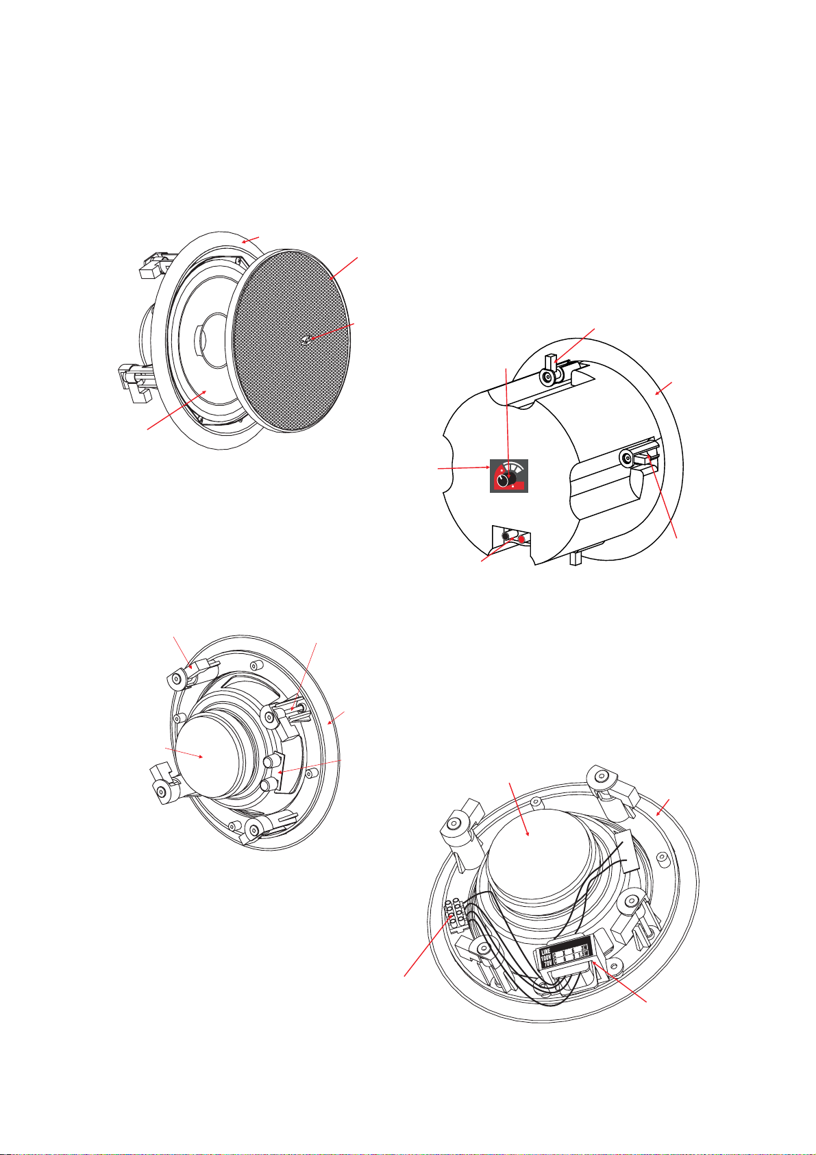
Descripción
A continuación se presentan unos gráficos
para identificar claramente cada una de las partes
que componen el producto y facilitar así su manejo
e instalación:
SOPORTE ALTAVOZ
SPEAKER S UPPORT
REJA
GRILLE
DAS
LOGO
ALTAVOZ
SPEAKER
Figura 1 – vista frontal de CL
ETIQUETA
DE ALTAVOZ
SPEAKER
LABEL
SELECTOR DE
MODO DE USO
USE MODE
SELECTOR
8
WARNING
WARNING
DO NOT USE T HE 8
DO NOT USE T HE 8
POSITION W ITH 100V/70V L IN ES
POSITION W ITH 100V/70V L IN ES
PESTAÑA GIRATORIA
PARA MONTAJE EN TECHO
ROTATING MOUNTING TAB
FOR CEILI NG MOUNTIN G
SOPORTE
DEL ALTAVOZ
SPEAKER
SUPPORT
0
0
V
1
L
I
N
E
5W 10W
15W
PESTAÑA GIRATORIA
PARA MONTAJE EN TECHO
ROTATING MOUNTING TAB
FOR CEILI NG MOUNTIN G
ETIQUETA
DE ALTAVOZ
SPEAKER
LABEL
Figura 2 – vista trasera CL-5, CL-6 y CL-8
TORNILLO PARA APRETAR
LA PESTAÑA GIRATORIA
ROTATING MOUNTING TAB
TIGHTENI G SCREW
SOPORTE
DEL ALTAVOZ
SPEAKER
SUPPORT
BORNAS
DE PRESIÓN
SPRING
TERMINAL S
BORNAS
DE PRESIÓN
SPRING
TERMINAL S
Figura 3 – vista trasera CL-6TB
ETIQUETA
DE ALTAVOZ
SPEAKER
LABEL
TORNILLO PARA
APRETAR LA
PESTAÑA GIRATORIA
ROTATING MOUNTING
TAB TIGHTENIG S CREW
SOPORTE
DEL ALTAVOZ
SPEAKER
SUPPORT
REGLETA DE
CONEXIÓN
SCREW
TERMINAL
Figura 4 – vista trasera
4
Manual del Usuario / Ceiling series / User’s Manual
CL-5T, CL-6T y CL-8T
TRANSFORMADOR
DE LÍNEA
LINE TRANSFORMER
Page 11

INSTALACIÓN
Consideraciones previas
Para la completa instalación del producto, es
necesario prever, tanto la realización
es en los lugares destinados a albergarlo,
circular
de orific
como el cableado para cada una de las unidades
existentes.
Para realizar las instalaciones
con los altavoces
de techo de D.A.S. Audio se pueden emplear
amplificadores convencionales, pudiendo realizar
por lo tanto dos configuraciones básicas con
productos de 8 ohmios de impedancia.
Tipos de instalación
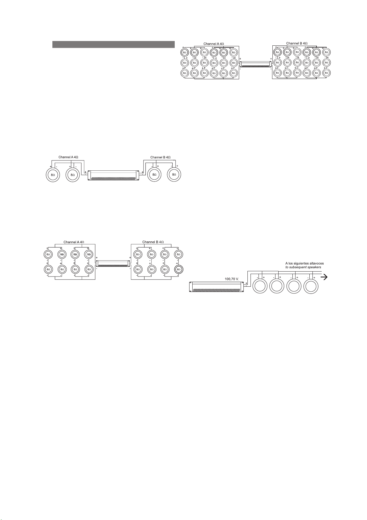
Configuración en paralelo, que permite colocar
2 unidades por canal para tener 4 ohmios de
impedancia:
Amplifier
Figura 5 - conexión paralelo
Configuración serie-paralelo, se colocan dos
cargas en paralelo por canal, cada carga consta
de 4 unidades en configuración serie-paralelo; en
total se pueden instalar 8 altavoces por canal:
Amplifier
ios
Figura 7 – conexión serie-paralelo con mayor número
de unidades por canal
Se ha de tener presente siempre que se opere
de esta forma que es necesario emplear un
amplificador que pueda dar suficiente potencia a 4
ohmios para todas las cargas situadas por canal.
Se evitará así, trabajar en saturación y provocar
rotura de los altavoces.
Por ejemplo, para el caso de la instalación
anterior suponiendo que se está empleando el
modelo CL-6 de 40W de potencia:
Existen en cada canal 18 unidades por tanto
se necesitan 18x40=720W por canal a 4 ohmios:
deberíamos emplear un amplificador que diera
entre 720 y 1000 W por canal aproximadamente
(entre el 100-150% de la potencia de aguante de
los altavoces).
Para realizar instalaciones en las que se
requiera un número mayor de altavoces es
necesario emplear un modelo con transformador
de línea incorporado.
Amplifier
Figura 6 - conexión serie-paralelo
Análogamente a esta configuración, si no se
desea emplear el modelo con transformador de
línea, se puede aumentar el número de unidades
de forma que siempre se obtengan 4 ohmios por
canal y así poder emplear amplificadores
convencionales; se deberá realizar la instalación de
la siguiente forma:
En cada canal del amplificador se conectarán
dos cargas en paralelo; cada una de ellas estará
formada por el paralelo de tantas cargas como
unidades en serie se desee instalar. Cada una de
éstas últimas cargas se compone de las unidades
en serie a instalar.
Por ejemplo, si se desea tener 3 cargas en
serie, en cada canal del amplificador se pondrán
dos cargas en paralelo; cada una de ellas formada
a su vez por otras tres cargas en paralelo. Cada
una de éstas últimas se compondrá de tres
unidades en serie (véase figura 7).
Amplifier
Figura 8 - Conexión en paralelo de unidades
con transformador
ATENCIÓN: ANTES DE INSTALAR LOS
ALTAVOCES ASEGÚRESE QUE HAY UN HUECO
CON ALTURA MÍNIMA DE 100mm PARA
REALIZAR LA INSTALACIÓN.
Instalación
A continuación se describe cada una de las
etapas que es necesario seguir para llevar a cabo
la instalación completa del producto. Se ha de
tener presente como paso previo a los que a
continuación se detallan, el cableado de toda la
instalación por el techo dejando los terminales
necesarios en los puntos donde se ha de instalar
un altavoz.
1.- Quitar reja del altavoz: Antes de comenzar
la instalación se debe retirar la reja del altavoz para
poder acceder a los tornillos. Para realizar la
operación, bastará con emplear algún objeto
puntiagudo e introducirlo en alguno de los
pequeños orificios circulares cercanos al borde de
la misma; si se realiza esta operación insertando el
ob j eto p un za nte en p un to s o pu est o s
diametralmente, la reja podrá retirarse sin esfuerzo
alguno.
Manual del Usuario / Ceiling series / User’s Manual
5
Page 12
AT E N C I ÓN: EXTRAIGA LA REJA CON
PRECAUCIÓN CUIDANDO NO DAÑAR EL
ALTAVOZ CON EL ÚTIL EMPLEADO PARA
REALIZAR LA ACTIVIDAD.
2.- Corte en el techo: Antes de realizar la
instalación es necesario realizar un orificio circular
en el techo en el cual introducir cada una de las
unidades; en la siguiente tabla se presentan los
diámetros internos del producto y las dimensiones
recomendadas para los orificios a realizar
(diámetro y profundidad):
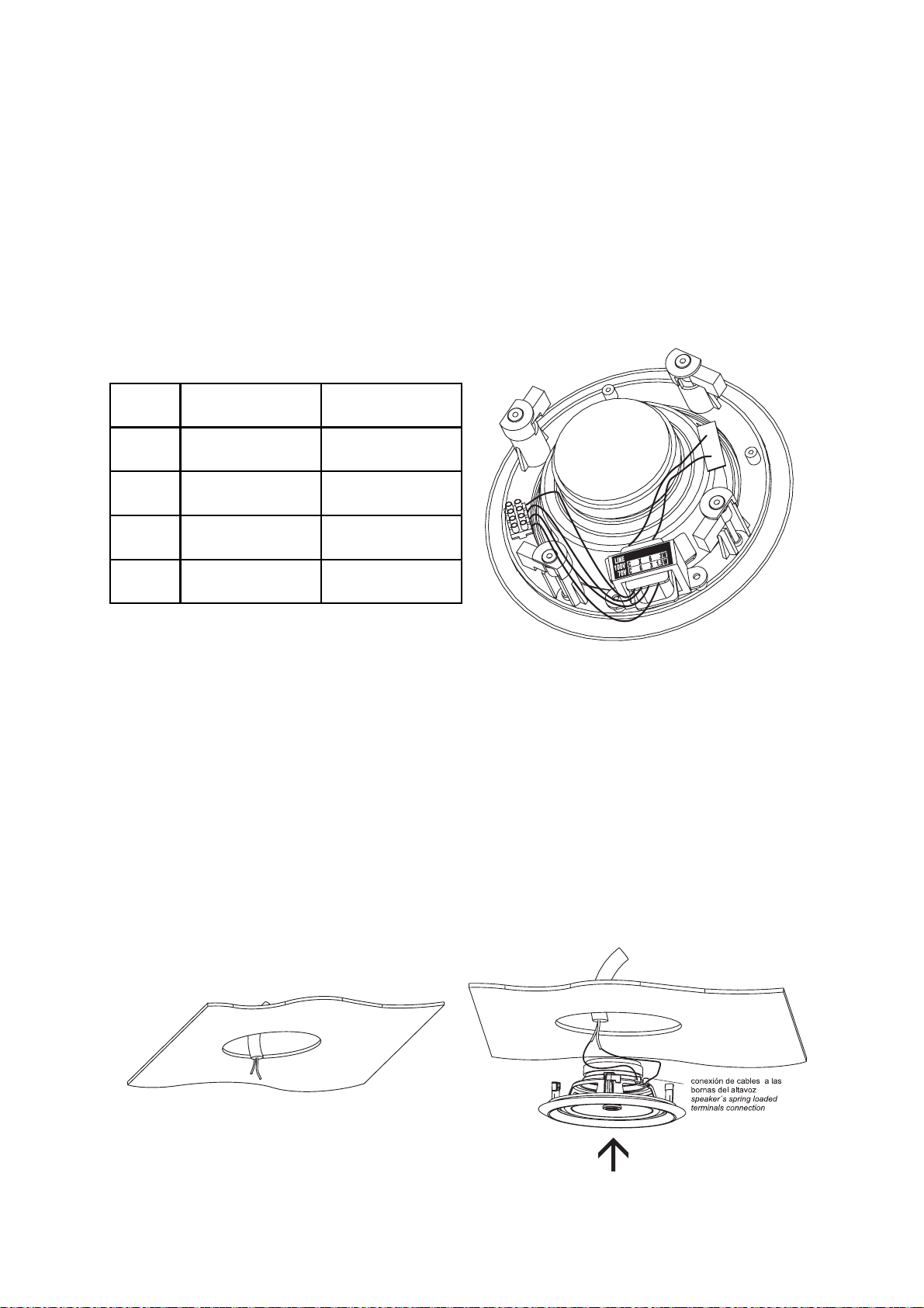
3.- Conexión de terminales: realizar la
conexión entre los terminales de los cables con las
bornas de presión del altavoz, cuidando mantener
correctamente la polaridad. Para insertar los
cables en las bornas, presione éstas para que
quede accesible el orificio donde insertar el
terminal; una vez hecho esto deje de hacer
presión y el cable habrá quedado fijado. Para el
modelo CL-5T se ha de seleccionar en primer lugar
la potencia a la que va a trabajar el altavoz
teniendo presente la tensión de alimentación; una
vez hecho esto se han de conectar los terminales
correspondientes a la potencia seleccionada (ver
figura 10).
MODELO
CL-5, CL-5T
CL-6, CL-6T
CL-8, CL-8T
CL-6TB
PROFUNDIDAD NECESARIA
(mm)
70
80
97
160
DIAMETRO DEL ORIFICIO
(mm)
166
194
238
206.5
Tabla 2: Tamaño del corte en el techo.
Dimensiones en mm.
Para facilitar la tarea se adjunta con el
producto una plantilla con forma circular para ser
empleada como guía a la hora de realizar el corte
en el techo, de esta forma el cliente no necesita
realizar medida alguna. Además de la plantilla de
corte, existe una para proteger el altavoz para
poder pintar el soporte de plástico (se trata del
círculo de menor diámetro dibujado en el patrón
de corte).
Por tanto, el paso primero se puede realizar de
dos formas, o bien empleando las medidas de la
tabla 2 para el diámetro del corte, o con la plantilla
de corte incluida en el producto. Una vez realizado
el corte se debe tirar de los cables de la
instalación para tenerlos accesibles a través del
orificio circular practicado.
Figura 10 – terminales para selección
de potencia en CL-5T
4.- Insertar altavoz en
orificio: para realizar
esta operación se han de seguir los siguientes
p
asos:
Ÿ Sostener
el altavoz con una mano, mientras
con la otra se introducen los cables de la
instalación, que se habían extraído previamente
para realizar las conexiones, dentro del corte
efectuado.
Ÿ Introducir el
que cada una de las
sirven
para fijarlo al techo quede
conjunto en el orificio cuidando
4 pestañas giratorias que
en posición
tangencial al corte, de otra manera no se podrá
colocar
el conjunto ya
que las propias pestañas
lo
impedirían.
Figura 9 – corte circular; cableado de
la instalación
Figura 11 – conexión de terminales;
posicionamiento del alt
6
Manual del Usuario / Ceiling series / User’s Manual
avoz
Page 13
ATENCIÓN:
POR EL SOPORTE DE PLÁSTICO DEL MISMO,
EVITE HACERLO
MEMBRANA, PODRÍA DAÑAR EL SISTEMA.
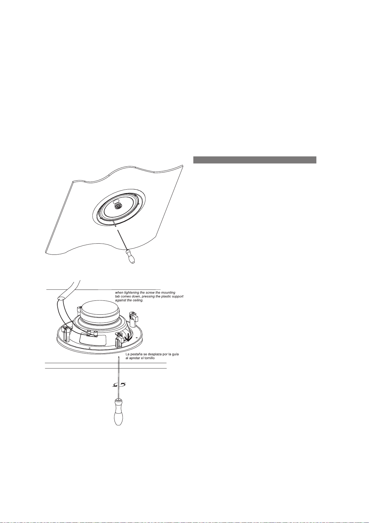
5.- Apretar los tornillos: para fijar el conjunto
se han de desplazar las pestañas para que
presionen el soporte contra el techo, hecho que
se consigue apr
desde la parte frontal. Se ha de proceder tal y
como sigue: para cada punto de fijación (en total
4) gire una vuelta apr
conseguir que la pestaña se
para eje rc e r presió n contra el te c ho.
Seguidamente apriete cada tornillo para que la
pestaña se mueva por la guía que existe en la
torreta hacia el techo.
SUJETE SIEMPRE EL ALTAVOZ
APOYÁNDOSE EN LA
etando los tornillos accesibles
oximadamente el tornillo para
oriente radialmente
6.- Colocar de nuevo la reja: una vez
apretados los tornillos el sistema ha quedado
fijado al techo, tan solo resta insertar la reja en su
encaje correspondiente.
La operación se puede realizar fácilmente
encarando la reja con el encaje correspondiente
que existe en el soporte de plástico y presionando
con la mano hasta que quede fijada. Se debe
emplear para fijar la reja al conjunto las tiras
adhesivas que se adjuntan con el producto.
Nota: la reja presenta cierta resistencia a ser
retirada; su fijación se realiza por contacto, es
decir la holgura entre su diámetro externo y el
interno del soporte es muy pequeña, siendo
necesario superar un pequeño rozamiento para
extraerla.
MANTENIMIENTO Y USO
No es necesario el mantenimiento de los
productos descritos en el presente manual
siempre y cuando se hayan instalado de forma
correcta y siguiendo las instrucciones del manual.
A continuación se describen algunas
precauciones que pueden resultar útiles para el
usuario:
Figura 12 – fijación del altavoz al techo
Es necesario recordar al usuario que el mejor
mantenimiento que se puede dar a un altavoz es
su correcta utilización, es decir, dentro de las
premisas para las que fue diseñado. Es importante
no emplear amplificadores demasiado grandes en
comparación con la potencia del altavoz, por lo
general se suele recomendar el empleo de
amplificadores que den entre el 100-150% de la
potencia del altavoz.
Instalar un amplificador de poca potencia es
igualmente peligroso porque se puede quemar el
altavoz por usar un amplificador demasiado
pequeño y llevarlo saturando a menudo. El recorte
o saturación (clip) es uno de los mayores
enemigos del altavoz. Por ello se recomienda que
si el amplificador entra en clip lo haga de forma
esporádica, y que la luz indicadora de recorte
nunca esté encendida de forma continuada.
En la práctica se tiende a saturar un
amplificador de potencia insuficiente porque no
nos entrega el nivel que esperamos. Usar un
amplificador de potencia reducida es una falsa
economía, puesto que hay que considerar el gasto
posterior en recambios. Por supuesto, además, un
sonido saturado está distorsionado y es
desagradable de escuchar.
Figura 13 –
al apretar el tornillo la pestaña se desplaza hacia
abajo oprimiendo el soporte
techo
funcionamiento del sistema de fijación:
de plástico contra el
Manual del Usuario / Ceiling series / User’s Manual
Otra situación que se debe evitar es colocar
demasiadas cargas en paralelo sin transformador,
situación que conduce a tener una impedancia
menor de 4 ohmios en cada canal, hecho que
provocaría que el amplificador sufriera una avería
por excesivo calentamiento.
7
Page 14

Manual del Usuario / Ceiling series / User’s Manual
Page 15

CONTENTS
INTRODUCTION
General
Features
Description
INSTALLATION
Preliminary considerations
Types of installation
Installation
MAINTENANCE & USE
3
5
7
Manual del Usuario / Ceiling series / User’s Manual
Page 16

CL-5 / CL-5T
CL-6 / CL-6T
CL-8 / CL-8T
Manual del Usuario / Ceiling series / User’s Manual
CL-6TB
Page 17

INTRODUCTION
General
Thank you for purchasing D.A.S. products.
This manual contains the required information to
make the best use of the system you have
purchased.
Please take the time to read it.
Features
Ÿ The materials and design uses for these units
represent advanced sound reinforcement
technology that delivers outstanding audio
performance from compact and easy-to-use
products. Sound field coverage is wide with
efficient mid and high frequency reproduction for
greater intelligibility.
Ÿ High induction magnetic circuits result in
reduced distortion and listening fatigue for spoken
voice and music reproduction.
Ÿ Polypropylene cones avoid age deterioration
when exposed to heat and air humidity.
Ÿ Technical specifications are shown in Table 1
for all models:
Note: Position marked with an “X” should not be
utilised.
Ÿ Thus, all models have eight screws, 4 for fixing
the speaker to its plastic support, and four that
operate the mounting tabs that fix the assembly to
the ceiling.
Ÿ All screws are accessed from the back, i.e. the
front grille must be removed for screwing /
unscrewing.
Ÿ All models are shipped with a tile cut out
template. If painting of the plastic ring is needed, a
round paper piece is also shipped to cover the rest
of the speaker when painting.
MODEL
CL-5
CL-6
CL-8
CL-6TB*
Nominal
Impedance
Averange [RMS]
Power Handling
(W)
8 20 89
8
8
8
(W)
40
60
40
Sensitivity
[on axis 1W/1m]
(dB SPL)
Frequency
range
(Hz)
70 - 15k
90
90
90
60 - 20k
50 - 20k
60 - 20k
Ÿ All models feature a removable protective grille
with a DAS logo, which allows access to the front
of the loudspeakers. For removal, a pointy object
needs to be introduced on a grille hole. For further
detail, consult section INSTALLATION of this
manual.
WARNING: BE CAREFUL NOT TO DAMAGE
THE CONE WITH THE POINTY OBJECT
WHEN REMOVING THE GRILLE
Ÿ Connection terminals are spring-loaded and
colour coded: red for positive, black for negative.
Transformer models have 4 terminals, a common
one plus three other ones that correspond to each
of the three possible selected input power levels.
Check the back label for the corresponding power
for different line voltages. Do not use the 6W
terminal for a 100V line.
Ÿ The label on the speaker’s back plate contains
the main product specifications and standard
compliances.
Ÿ All models comprise three main elements: the
plastic support, the speaker and the grille. The
back of the support houses four small turrets for
the screws that fix the speaker chassis, plus other
four larger turrets. The latter house the tabs that fix
the speaker assembly to the ceiling tile assembly
when rotating the turrets’ screws.
Nominal
MODEL
CL-5T
CL-6T
CL-8T
CL-6TB*
* Can be used at low impedance or distributed line.
Impedance
(W)
100
70
100
70
100
70
100
70
Averange [RMS]
Power Handling
(W)
3 - 6 - X
1.5 - 3 - 6
5 - 10 - 15
2.5 - 5 - 7.5
10 - 20 - 30
5 - 10 - 15
5 - 10 - 15
2.5 - 5 - 7.5
[on axis 1W/1m]
Table 1: Specifications
Sensitivity
(dB SPL)
89
90
90
90
Frequency
range
(Hz)
70 - 15k
60 - 20k
50 - 20k
60 - 20k
Manual del Usuario / Ceiling series / User’s Manual
3
Page 18

Description
All ceiling series models (front and back) can be
seen below.
The exploded view below identifies the different
elements to ease handling and installation.
SOPORTE ALTAVOZ
SPEAKER S UPPORT
REJA
GRILLE
DAS
LOGO
ALTAVOZ
SPEAKER
Fig. 1 – CL front view
ETIQUETA
DE ALTAVOZ
SPEAKER
LABEL
SELECTOR DE
MODO DE USO
USE MODE
SELECTOR
8
WARNING
WARNING
DO NOT USE TH E 8
DO NOT USE TH E 8
POSITION W ITH 100V/70V L IN ES
POSITION W ITH 100V/70V L IN ES
PESTAÑA GIRATORIA
PARA MONTAJE EN TECHO
ROTATING MOUNTING TAB
FOR CEILI NG MOUNTIN G
SOPORTE
DEL ALTAVOZ
SPEAKER
SUPPORT
0
0
V
1
L
I
N
E
5W 10W
15W
PESTAÑA GIRATORIA
PARA MONTAJE EN TECHO
ROTATING MOUNTING TAB
FOR CEILI NG MOUNTIN G
ETIQUETA
DE ALTAVOZ
SPEAKER
LABEL
Fig. 2 – CL-5
TORNILLO PARA APRETAR
LA PESTAÑA GIRATORIA
ROTATING MOUNTING TAB
TIGHTENI G SCREW
, CL-6 & CL-8 back view
SOPORTE
DEL ALTAVOZ
SPEAKER
SUPPORT
BORNAS
DE PRESIÓN
SPRING
TERMINAL S
BORNAS
DE PRESIÓN
SPRING
TERMINAL S
Fig. 3 – CL-6TB back view
ETIQUETA
DE ALTAVOZ
SPEAKER
LABEL
TORNILLO PARA
APRETAR LA
PESTAÑA GIRATORIA
ROTATING MOUNTING
TAB TIGHTENIG S CREW
SOPORTE
DEL ALTAVOZ
SPEAKER
SUPPORT
REGLETA DE
CONEXIÓN
SCREW
TERMINAL
Fig. 4 – CL-5T
4
Manual del Usuario / Ceiling series / User’s Manual
, CL-6T y CL-8T
TRANSFORMADOR
DE LÍNEA
LINE TRANSFORMER
back view
Page 19
INSTALLATION
Preliminary considerations
For complete installation
time to plan ahead
, we need to take the
the cutting out tile holes and
the cabling of the units.
Conventional amplifiers can be used to power
DAS ceiling speakers. With them, two types of
the
wiring configurations are possible.
Types of installation
A parallel configuration allows the use of two
speakers per channel for a 4 ohm load:
Amplifier
Fig. 5 – parallel connection
Series-parallel connection. Two loads are wired
per channel,
connected in series-parallel. A total of 8 speakers
per channel can be installed this way:
each load consisting of four units
Amplifier
Fig. 7 – Series-parallel connection of a large
number of speakers per channel
When working
wired this
way, one should ensure that all speakers
get enough power.
Otherwise the user will tend
amplifier, which in turn
failure.
Example: for the system on the illustration,
assuming CL-6 (40W):
Each channel drives 18 units, for a total of
8x40=720W worth of speaker power handling.
Since amplifier channel should be 100-150% of
the speakers’ power handling, 720 to 1000 W
should be used for amplifier power (at 4 ohm).
For very
models should be used.
with a large number of units
to overload the
may result in speaker
large installations, the line transformer
Amplifier
Fig. 6 - series-parallel connection
Similarly, if one does not wish
transformer model, the number
to use a
of units in seriesparallel can be increased, as long as 4 or more
ohms impedance
Each amplifier will drive two load
Each will consist of the
is achieved, as follows.
s in parallel.
parallel connection
of as
many loads as we want to connect in series. Each
of the latter loads consists of the units to be series
connected (see Fig.7).
Amplifier
Fig. 8 – Parallel connection of transformer units
WAR N IN G: B EF OR E I NS TALL IN G T H E
SPEAKERS, MAKE SURE THERE IS A MINIMUM
CEILING VOID HEIGHT OF 100 mm (4”).
Installation
The different installation steps are described.
Before this can take place, the installation should
be wired, leaving all of the ceiling wiring in place
and ready for connection.
Step 1 – Remove the speaker grille: The grille
must be removed for access to the mounting
screws. Insert a pointy object and introduce it in a
grille hole close to the edge. You’ll remove the
grille with ease if using two pointy objects on
opposite ends.
Manual del Usuario / Ceiling series / User’s Manual
5
Page 20

WARNING: BE CAREFUL NOT TO DAMAGE
THE CONE WITH THE POINTY OBJECT WHEN
REMOVING THE GRILLE
Step 2 – Ceiling tile cut out: The following
table lists the inner and recommended cut out
diameters for the different models and the
necessary depth in the ceiling structure to install
the speakers:
Step 3 – Terminal connection: the speakers
terminals are spring loaded. Watch the colour
coding for polarity. For connection to transformer
models, you will need to select the required input
power and connect to the appropriate terminals
(see Fig. 10).
MODEL
CL-5, CL-5T
CL-6, CL-6T
CL-8, CL-8T
CL-6TB
DEPTH REQUIRED
(in)
2.76
3.15
3.82
6.3
CUT OUT DIAMETER
(in)
6.65
7.76
9.52
8.13
Table 2: inner and cut out diameters
Packaged with the speakers is a cardboard cut
out template for scribing the cut out hole onto your
ceiling surface. The inside circumference of the
same template can be used to cover the rest of
the speaker when painting.
Therefore the cut out may be scribed using the
template provided or by drawing a circumference
of the diameter in table 2. Once the hole is cut,
you may need to pull down the cables so they are
accessible for connection.
Fig. 10 – CL-5T; input power selection terminals
Step 4 – Inserting the speaker: follow these
steps:
old the speaker in one hand, while you use
Ÿ H
the other hand to connect the cable to the
speaker.
Ÿ Push the assembly all the way into
four mounting tabs
must be tangential to
hole. The
the ring,
otherwise they’ll be in the way.
Fig. 9 – circular cut out, installation wiring
6
Manual del Usuario / Ceiling series / User’s Manual
Fig. 11 – terminal connection; speaker positioning
Page 21

SPEAKER
WARNING
THE PLASTIC SUPPORT, AVOIDING DAMAGE
TO THE TRANSDUCER DIAPHRAGMS
: ALWAYS HOLD
THE
BY
Step 5 – Screwing and fixing: to fix the
assembly to the ceiling, the tabs have to be
rotated and lowered. This is done by tightening the
corresponding screws clockwise. The first quarter
turn rotates the tab into position and out of the
guide; the rest tightens the tab down onto the
back of the ceiling surface. The process needs to
be repeated for all four screws.
Fig. 12 – fixing the speaker to the ceiling
Step 6 – Replace the grille: once the speaker
is fixed to the ceiling, this is the only operation left.
Push the grille into place until fixed. You will
need to use the adhesives stripes provided.
Note: the grille shows some degree of
resistance to be removed. Fixing is by contact, so
there is little clearance between its inner diameter
and the inner support, so that some force needs
to be applied when removing it.
MAINTENANCE & USE
No maintenance is needed for the products in
this manual if they have been installed correctly
and following the instructions in this manual.
Some usage tips follow:
The best maintenance for a speaker is its
correct use, i.e., within the design parameters. It is
important not to utilise amplifiers that are too large
when compared to the speaker power. In general,
it is recommended that you use an amplifier with
an output that is 100% to 150% of the speaker's
average (RMS) power rating.
Fig. 13 – fixing system: when tightening the
screw the mounting tab comes down, pressing
the plastic support against the ceiling.
That way we have headroom for the dynamics
of real music and vocal signals, and at the same
time deliver a cleaner signal to the speakers that
will result in a more reliable system. Avoid using
too small an amplifier. The clip light of your
amplifiers should never be on continuously. This
will distort the signal and may damage the
speakers. In fact, severe clipping is an easy way to
burn a speaker’s voice coil. At most, the clip light
could blink occasionally. When clipped, signals
sound distorted and produce listening fatigue
quickly. Never use a total impedance load that is
lower than the lowest impedance that an amplifier
will take.
Virtually all professional amplifiers will accept
loads down to four ohms safely in stereo mode.
Many are rated for two ohm loads but often will
run into overheating protection when used this
way, particularly in high ambient temperature and
high output power applications.
Never connect more speakers to an amplifier's
channel than it will take, i.e. do not load a channel
with total impedance that is lower than the
minimum load specified by the manufacturer.
Manual del Usuario / Ceiling series / User’s Manual
7
Page 22

Manual del Usuario / Ceiling series / User’s Manual
Page 23

Page 24

www.dasaudio.com
UM_CL_03
D.A.S. AUDIO, S.A.
C/. Islas Baleares, 24
46988 Fuente del Jarro
Valencia, SPAIN
Tel. 96 134 0525
Tel. Intl. +34 96 134 0860
Fax 96 134 0607
Fax Intl. +34 96 134 0607
D.A.S. AUDIO OF AMERICA, INC.
Sunset Palmetto Park
6816 NW 77th Court.
Miami, FL. 33166 - U.S.A.
TOLL FREE: 1-888DAS4USA
Tel. +1 305 436 0521
Fax +1 305 436 0528
D.A.S. AUDIO ASIA PTE. LTD.
25 Kaki Bukit Crescent #01-00/02-00
Kaki Bukit Techpark 1
Singapore 416256
Tel. +65 6742 0151
Fax +65 6742 0157
 Loading...