

DAS ARTEC-506 Datasheet
Artec series
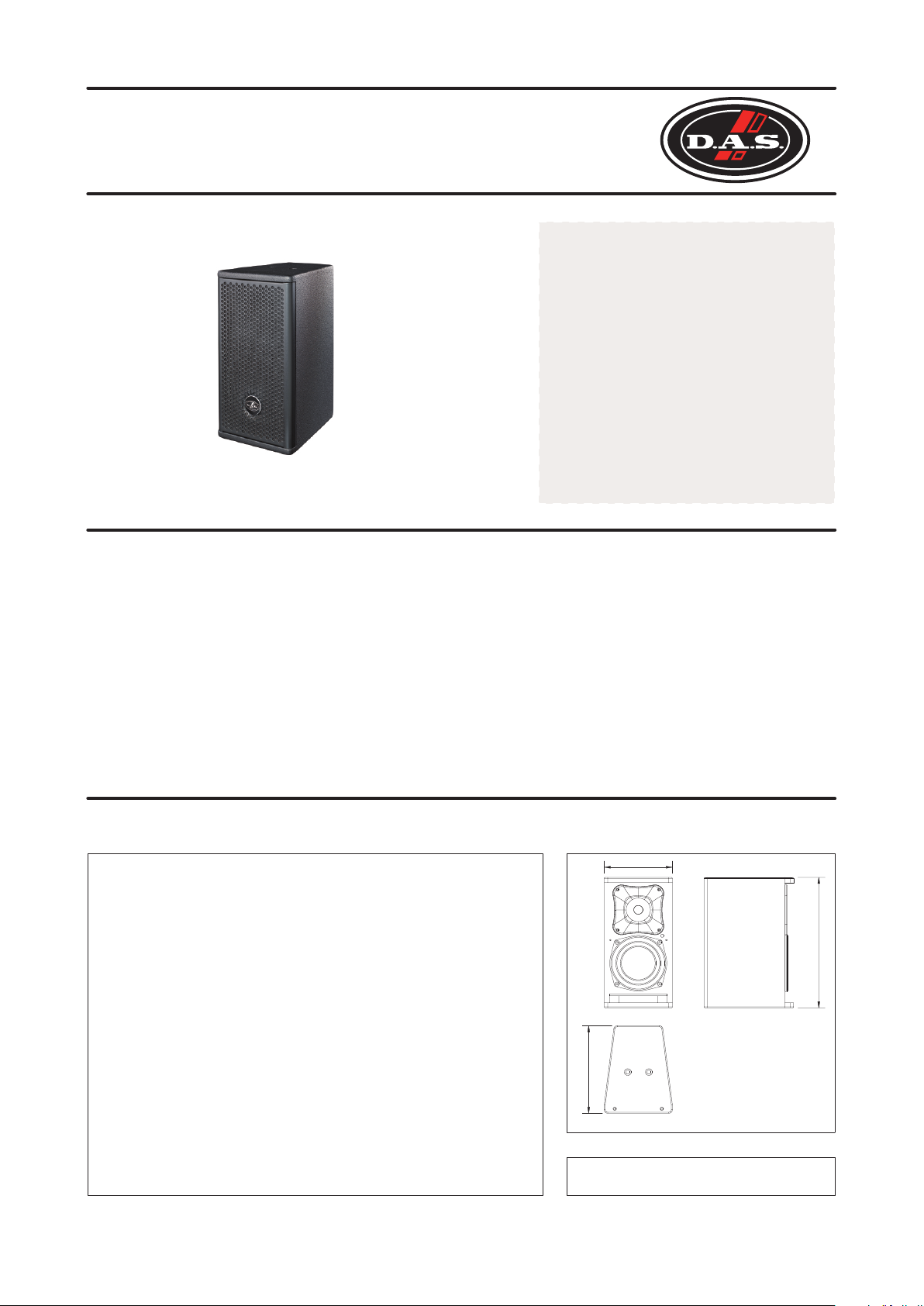
Artec 506
LOUDSPEAKER SYSTEM
The D.A.S. Artec 506 is a two-way vented
loudspeaker system designed for
applications covering speech reinforcement
and program reproduction.
The low end utilizes a high efficiency 6” low
frequency speaker with 2” voice coil.
The high end makes use of a 1” exit
compression driver with 1.75” titanium
diaphragm, coupled to a 80º x 80º horn.
TWO-WAY VENTED
>> Two-way vented
loudspeaker system
>> 1 x 6” cone speaker
>> 1” exit compression
driver with constant
directivity horn
>> 200 W rms power
handling
The unit has a robust grille design
internally lined with acoustically
transparent filter cloth to protect the
loudspeaker components. The covering is
resistant to wear and tear, provides
protection from dust and dirt.
4 integrated rigging points that accept
10M forged steel eyebolts or “U” braket
make suspension in either the horizontal
or vertical positions safe and simple.
Technical Specifications
RMS (Average) Power Handling
Program Power handling
Peak Power Handling
On-axis Frequency Range
Nominal Impedance
Minimum Impedance
On-axis Sensitivity 1W/1m
Rated Peak SPL at Full Power
Nominal -6dB Beamwidths
Enclosure Material
Color/Finish
Transducers/Replacement Parts
Connector
Dimensions (H x W x D)
Weight
Accesories (optional)
P
K
R
200 W
400 W
800 W
65 Hz - 20 kHz
8 ohm
6.3 ohm at 240 Hz
90 dB SPL
122 dB SPL
80º Horizontal x 80º Vertical
Wisa® Birch Plywood
Isoflex Black Paint
LF: 6P / 6P
HF: M34 / GM-M-34
2 paralleled NL4 Speakon,
wired to +/-1
38 x 19.4 x 25.5 cm
15 x 7.7 x 10 in
7 kg (15.4 lb)
ANL-2
TRD-6 + AXC-ZT
TRD-2 + AXC-ZT
AXU-A506
AXW-1
AXR-A500
Dimensions
194
225555
ALL DIMENSIONS IN MILIMETERS
R
Based on a 2 hour test using a 6dB crest factor pink noise signal
P
Conventionally, 3dB higher than the RMS measure
k R
Corresponds to the signal crests for the test described in
380

Artec 506
Artec series
Frequency Response
Shows the frequency
response at 1m of a unit
radiating to an anechoic
environement (4p) and
driven by a 1w (2.83 V)
swept sine signal, and
impedance curve. For better
detail, only light smoothing
(1/12th octave) has been used.
Distortion
Shows the Second Harmonic
Distortion (grey) and Third
Harmonic Distortion (dotted)
curves for a unit driven at
10% of its nominal power
rating. Rised 20dB for clarity.
Directivity
Shows normalized horizontal
isobar plot
110.0
dBSPL
100.0
90.0
80.0
70.0
6y0.0
10 100 1k 10k 20k10 Hz
120.0
dBSPL
110.0
100.0
90.0
80.0
70.0
10 100 1k 10k 20k10 Hz
100.0
Ohm
80.0
60.0
40.0
20.0
0.0
0
dB
-10
-20
-30
Directivity
Shows normalized vertical
isobar plot
Polar Response
1/3 octave band horizontal (left)
and vertical (right) polars for
the indicated frequencies. Full
scale is 30dB, 6dB per division.
125Hz
250Hz
500Hz
1000Hz
2000Hz
4000Hz
8000Hz
12500Hz
-40
500200
500200
Left
-30°
-60°
-90°
-120°
-150°
6
dB
0
-6
-12
-18
-24
180°
Ref 0 1/3 Octave
1k100 10k 12k5 Hz
1k
1k
Right
30°
60°
90°
120°
150°
Ref 0 1/3 Octave
2k
2k
-120°
-150°
180°
150°
120°
5k100 10k 12k5 Hz
5k100 10k 12k5 Hz
-90°
90°
-60°
-18
-12
-24
60°
-50
0
dB
-10
-20
-30
-40
-50
Up
-30°
0
-6
dB
6
Down
30°
NOTES: Frequency response measured at 4m (13.12ft). For better detail, only light smoothing
(1/12th octave) has been used. Polars were acquired by placing the unit on a computer controlled
turntable inside a 300 m (10594 ft ) anechoic chamber. Measurement distance is 4m (13.12ft).
3 3
Product improvement through research and development is a
continuous process at D.A.S. Audio. All specifications subject
to change without notice.
 Loading...