

Page 1
User's Manual
ARTEC-306 / ARTEC-308 / ARTEC-326
ARTEC-310.96 / ARTEC-310.64
ARTEC-312.96 /ARTEC-312.64
ARTEC-315.96 /ARTEC-315.64
ARTEC-320 / ARTEC-322S
Antes de utilizar el equipo, lea la sección
“Precauciones de seguridad” de este manual.
Conserve este manual para futuras consultas.
Before operating the device, please read the
“Safety precautions” section of this manual.
Retain this manual for future reference.
Page 2

CONTENTS
SAFETY PRECAUTIONS
WARRANTY
DECLARATION OF CONFORMITY
INTRODUCTION
CONFIGURATIONS
4x ARTEC-306 / ARTEC-308 / ARTEC-310.XX + 2x ARTEC-322S
4x ARTEC-312.XX / ARTEC-315.XX + 2x ARTEC-322S
12x ARTEC-320 + 4x ARTEC-322S
LINE DRAWINGS
INSTALLATION & ACCESSORIES
ANNEX: Table for cable selection
3
4
5
6 - 8
9 - 11
12 - 13SPECIFICATIONS
14 - 15
16 - 21
22
Manual del Usuario / artec 300 series / User’s Manual
Page 3

artec 300 series
Cajas acústicas pasivas / Passive loudspeaker enclosures
Precauciones de Seguridad
Safety Precautions
Conserve y lea todas estas instrucciones.
Siga todas las advertencias.
El signo de exclamación dentro de un triángulo indica la
existencia de componentes internos cuyo reemplazo puede
afectar a la seguridad.
El doble cuadrado indica equipo de Clase II. The double square indicates Class II device.
Las especificaciones se encuentran en la etiqueta de la parte
posterior del producto.
El colgado del equipo sólo debe realizarse utilizando los herrajes
de colgado recomendados y por personal cualificado.
No exponga este equipo a la lluvia o humedad. No exponga el
equipo a salpicaduras ni coloque sobre él objetos que
contengan líquidos, tales como vasos y botellas. Equipo IP-20.
Este símbolo indica que el presente producto no puede ser
tratado como residuo doméstico normal, sino que debe
entregarse en el correspondiente punto de recogida de equipos
eléctricos y electrónicos.
Equipo diseñado para funcionar entre 15ºC y 42ºC con una
humedad relativa máxima del 95%.
El cableado exterior conectado al equipo requiere de su
instalación por una persona instruida.
Keep these instructions.
Heed all warnings. Follow all instructions.
The exclamation point inside an equilateral triangle indicates the
existence of internal components whose substitution may affect
safety.
The specifications can be found on the rear label of the product.
The appliance should be flown only from the rigging points and
by qualified personnel.
Do not expose this device to rain or moisture. Do not place any
objects containing liquids, such as bottles or glasses, on the top
of the unit. Do not splash liquids on the unit. IP-20 equipment.
This symbol on the product indicates that this product should
not be treated as household waste. Instead it shall be handed
over to the appicable collection point for the recycling of
electrical and electronic equipment.
Working temperature ranges from 15ºC to 42ºC with a relative
humidity of 95%.
The outer wiring connected to the device requires installation by
an instructed person.
El equipo cuenta con un terminal de entrada tipo regleta de
tornillo para facilitar la conexión.
No emplace altavoces en proximidad a equipos sensibles a
campos magnéticos, tales como monitores de televisión o
material magnético de almacenamiento de datos.
No existen partes ajustables por el usuario en el interior de este
equipo. Cualquier operación de mantenimiento o reparación
debe ser realizada por personal cualificado. Es necesario el
servicio técnico cuando el aparato se haya dañado de alguna
forma, tal como que haya caído líquido o algún objeto en el
interior del aparato, haya sido expuesto a lluvia o humedad, no
funcione correctamente o haya recibido un golpe.
Limpie con un paño seco. No use limpiadores con disolventes.
Device with terminal strip input to provide an easy connection.
Do not place loudspeakers in proximity to devices sensitive to
magnetic fields such as television monitors or data storage
magnetic material.
No user serviceable parts inside. Refer all servicing to qualified
service personnel. Servicing is required when the apparatus has
been damaged in any way, such as power-supply cord or plug is
damaged, liquid has been spilled or objects have fallen into the
apparatus, the apparatus has been exposed to rain or moisture,
does not operate normally or has been dropped.
Clean only with a dry cloth. Do not use any solvent based
cleaners.
Manual del Usuario / artec 300 series / User’s Manual
3
Page 4

GARANTÍA
Todos nuestros productos están garantizados por un periodo de 24
meses desde la fecha de compra.
Las garantías sólo serán válidas si son por un defecto de
fabricación y en ningún caso por un uso incorrecto del producto.
Las reparaciones en garantía pueden ser realizadas,
exclusivamente, por el fabricante o el servicio de asistencia técnica
autorizado.
Otros cargos como portes y seguros, son a cargo del comprador
en todos los casos.
Para solicitar reparación en garantía es imprescindible que el
producto no haya sido previamente manipulado e incluir una
fotocopia de la factura de compra.
WARRANTY
All our products are warrantied against any manufacturing defect
for a period of 2 years from date of purchase.
The warranty excludes damage from incorrect use of the product.
All warranty repairs must be exclusively undertaken by the factory
or any of its authorised service centers.
To claim a warranty repair, do not open or intend to repair the
product.
Return the damaged unit, at shippers risk and freight prepaid, to
the nearest service center with a copy of the purchase invoice.
4
Manual del Usuario / artec 300 series / User’s Manual
Page 5

DECLARACIÓN DE CONFORMIDAD
DECLARATION OF CONFORMITY
DAS Audio Group, S.L.
C/ Islas Baleares, 24 - 46988 - Pol. Fuente del Jarro - Valencia. España
(Spain).
Declara que la serie artec 300:
Declares that artec 300 series:
Cumple con los objetivos esenciales de las Directivas:
Abide by essential objectives relating Directives:
l De Baja Tensión / Low Voltage 2014/35/UE
l RoHS 2011/65/UE
l RAEE (WEEE) 2012/19/UE
Y es conforme a las siguientes Normas Armonizadas Europeas:
In accordance with Harmonized European Norms:
l EN 60065:2014.- Audio, video and similar electronic apparatus. Safety
requirements.
l EN 50581:2012.- Technical documentation for the assessment of
electrical and electronic products with respect to the restriction of
hazardous substances.
Manual del Usuario / artec 300 series / User’s Manual
5
Page 6
INTRODUCTION
The artec 300 series full range systems have been designed to provide wide bandwidth and high SPL in a
visually discrete package. The artec 300 products can be installed on walls, ceilings or columns thanks to an
extensive selection of optional mounting accessories. The ideal choice for under balcony, area fill and near
field applications, their reduced dimensions and sleek styling fits perfectly into multiple surroundings including
hotels and restaurants, from elegant nightclub installations to educational facilities.
Features
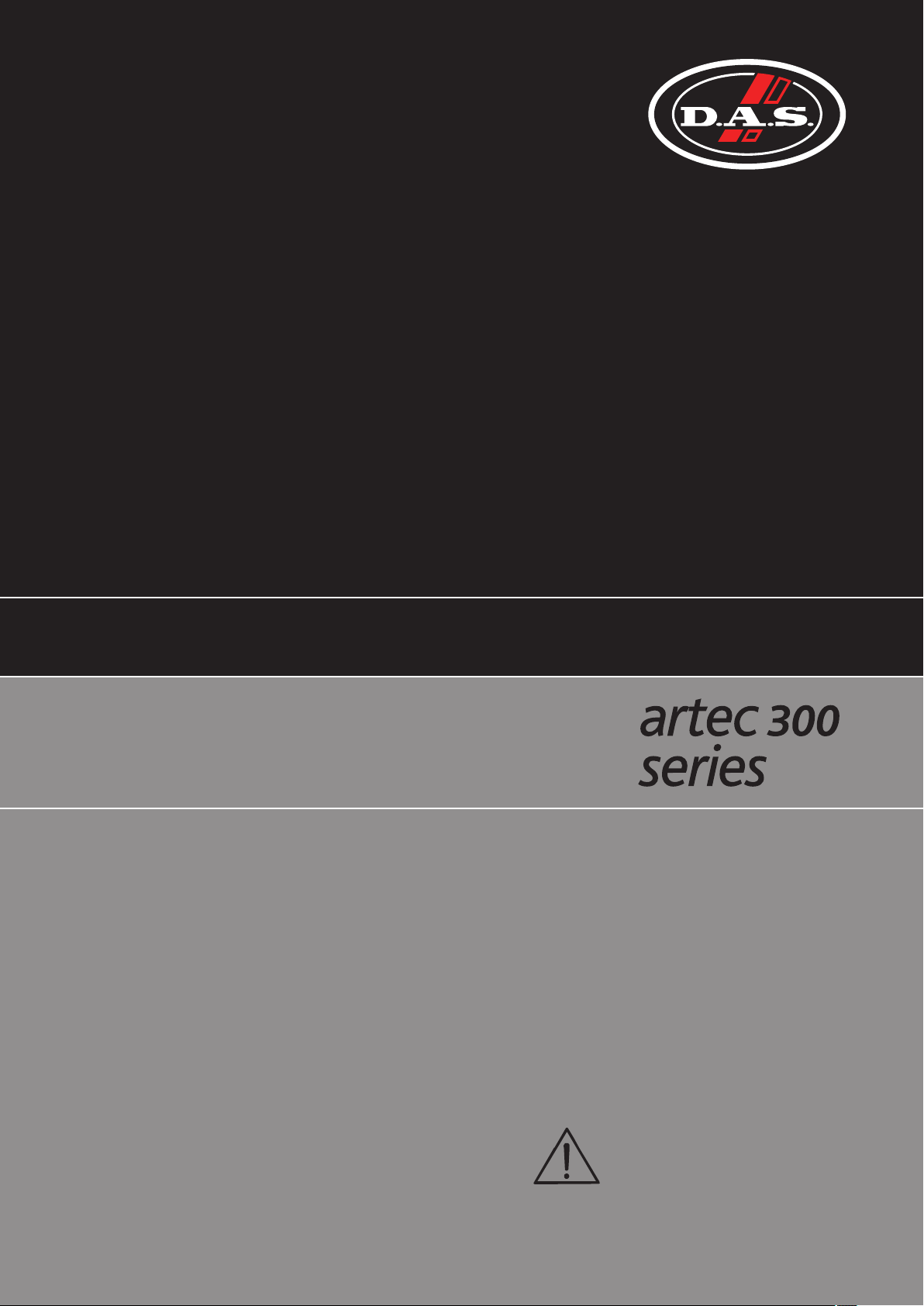
ARTEC-306
ARTEC-308
ARTEC-306
- 1x 6” low frequency loudspeaker
- 1x 1” exit compression driver
- Rotatable 90ºx60º horn
- Vertical or horizontal positioning
- VESA-75/VESA-100 standard threaded mounting points
- Versions with factory-installed line transformer and black or white finishes
available.
The ARTEC-306 employs a single 6" woofer for low frequency
reproduction. The M-26 compression driver provides the highs. The birch
plywood cabinet construction offers an ultra-compact design which is
available in black or white. Precise coverage and control in either the
horizontal or vertical position is possible thanks to the 90ºx60º horn geometry.
The cabinets can be permanently installed by way of the included “U”
brackets and the other optional accessories which allow for multiple
configurations. Four threaded fixing points for the wall mount and stand
mounting accessories augment adaptability. A robust steel grille internally
lined with acoustically transparent filter cloth protects components.
ARTEC-308
- 1x 8” low frequency loudspeaker
- 1x 1” exit compression driver
- Rotatable 90ºx60º horn
- Vertical or horizontal positioning
- VESA-75/VESA-100 standard threaded mounting points
- Versions with factory-installed line transformer and black or white finishes
available.
ARTEC-310.96
ARTEC-310.64
The ARTEC-308 employs a single 8" woofer for low frequency
reproduction. The M-26 compression driver provides the highs. The birch
plywood cabinet construction offers an ultra-compact design which is
available in black or white. Precise coverage and control in either the
horizontal or vertical position is possible thanks to the 90ºx60º horn geometry.
The cabinets can be permanently installed by way of the included “U”
brackets and the other optional accessories which allow for multiple
configurations. Four threaded fixing points for the wall mount and stand
mounting accessories augment adaptability. A robust steel grille internally
lined with acoustically transparent filter cloth protects components.
ARTEC-310.96 / ARTEC-310.64
- 1x 10” low frequency loudspeaker
- 1x 1” exit compression driver
- Rotatable 90ºx60º / 60ºx40º horn (different models)
- Vertical or horizontal positioning
- VESA-75/VESA-100 standard threaded mounting points
- Versions with factory-installed line transformer and black or white finishes
available.
The ARTEC-310.XX employs a single 10" woofer for low frequency
reproduction. The M-34 compression driver provides the highs. The birch
plywood cabinet construction offers an ultra-compact design which is
available in black or white. Precise coverage and control in either the
horizontal or vertical position is possible thanks to the 90ºx60º horn geometry
in ARTEC-310.96, or the 60ºx40º horn geometry in ARTEC-310.64. The cabinets
can be permanently installed by way of the included “U” brackets and the
other optional accessories which allow for multiple configurations. Four
threaded fixing points for the wall mount and stand mounting accessories
augment adaptability. A robust steel grille internally lined with acoustically
transparent filter cloth protects components.
6
Manual del Usuario / artec 300 series / User’s Manual
Page 7
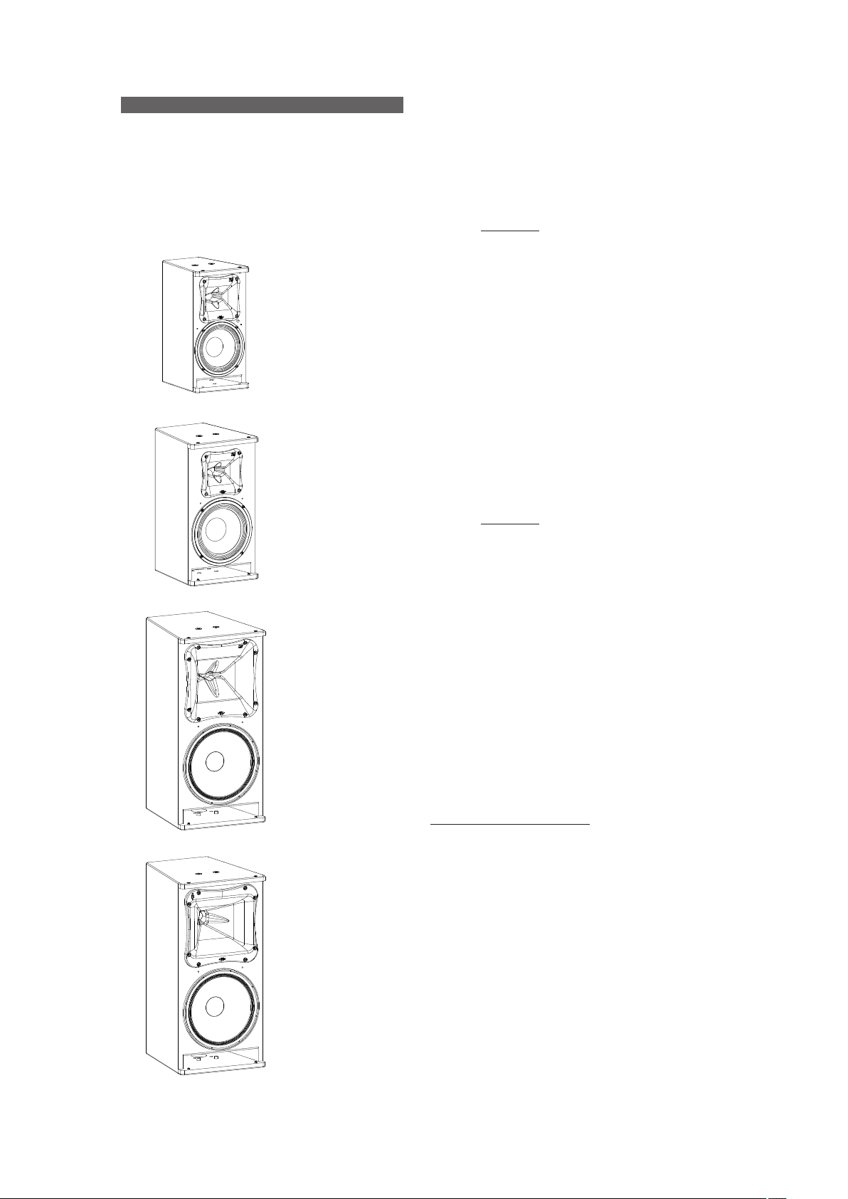
ARTEC-326
- 2x 6” low frequency loudspeaker
- 1x 1” exit compression driver
- Rotatable 90ºx60º horn
- Vertical or horizontal positioning
- VESA-75/VESA-100 standard threaded mounting points
- Versions with factory-installed line transformer and black or white finishes
available.
ARTEC-326
ARTEC-312.96
ARTEC-312.64
The 326 employs dual 6" woofers for low frequency reproduction. ARTEC-
The M-26 compression driver provides the highs. The birch plywood cabinet
construction offers an ultra-compact design which is available in black or
white. Precise coverage and control in either the horizontal or vertical position
is possible thanks to the 90ºx60º horn geometry. The cabinets can be
permanently installed by way of the included “U” brackets and the other
optional accessories which allow for multiple configurations. Four threaded
fixing points for the wall mount and stand mounting accessories augment
adaptability. A robust steel grille internally lined with acoustically transparent
filter cloth protects components.
ARTEC-312.96 / ARTEC-312.64
- 1x 12” low frequency loudspeaker
- 1x 1” exit compression driver
- Rotatable 90ºx60º / 60ºx40º horn (different models)
- Vertical or horizontal positioning
- Versions black or white finishes available.
The 312.XX employs a single 12" woofer for low frequency ARTEC-
reproduction. The M-34 compression driver provides the highs. The birch
plywood cabinet construction offers an ultra-compact design which is
available in black or white. Precise coverage and control in either the
horizontal or vertical position is possible thanks to the 90ºx60º horn geometry
in 312.96, or the 60ºx40º horn geometry in 312.64. The cabinets ARTEC- ARTEC-
can be permanently installed by way of the optional “U” brackets and
accessories which allow for multiple configurations. Four threaded fixing
points for the wall mount and stand mounting accessories augment
adaptability. A robust steel grille internally lined with acoustically transparent
filter cloth protects components.
ARTEC-315.96
ARTEC-315.64
ARTEC-315.96 / ARTEC-315.64
- 1x 15” low frequency loudspeaker
- 1x 1” exit compression driver
- Rotatable 90ºx60º / 60ºx40º horn (different models)
- Vertical or horizontal positioning
- Versions black or white finishes available.
The 315.XX employs a single 15" woofer for low frequency ARTEC-
reproduction. The M-34 compression driver provides the highs. The birch
plywood cabinet construction offers an ultra-compact design which is
available in black or white. Precise coverage and control in either the
horizontal or vertical position is possible thanks to the 90ºx60º horn geometry
in 315.96, or the 60ºx40º horn geometry in 315.64. The cabinets ARTEC- ARTEC-
can be permanently installed by way of the optional “U” brackets and
accessories which allow for multiple configurations. Four threaded fixing
points for the wall mount and stand mounting accessories augment
adaptability. A robust steel grille internally lined with acoustically transparent
filter cloth protects components.
Manual del Usuario / artec 300 series / User’s Manual
7
Page 8

ARTEC-320
ARTEC-320
- Two-way installation line array
- 2x 10” low frequency loudspeaker
- Compression driver with 3" titanium diaphragm and 1.5” exit
- Rigging system for installation compatible with ARTEC-322S
- Versions black or white finishes available.
The ARTEC-320 system is a two-way line array for installation with
dual 10" low frequency speakers, and a compression driver with 3"
titanium diaphragm and 1.5” exit for the highs. The birch plywood
cabinet construction offers an ultra-compact design which is available in
black or white. The high frequency waveguide is the same as the
waveguide incorporated in the prestigious event series. A rugged
protective steel grille safeguards the DAS components.
The JP-320 (included in ARTEC-320) are accessories that permit the
system array assembly, whereas the AX-AR3 (optional) is needed for the
rigging system.
ARTEC-322S
- Compact band-pass subwoofer system
- Dual 12” low frequency loudspeakers
- Enclosure designed for an easy stacking
- Rigging system compatible with ARTEC-320
- Versions black or white finishes available.
ARTEC-322S
The ARTEC-322S is a band-pass subwoofer system with dual 12P low
frequency loudspeakers. The loudspeaker is protected by a perforated
steel grille, sealed against corrosion using a powder coat finish. The
birch plywood cabinet construction offers an ultra-compact design which
is available in black or white. The ARTEC-322S is designed for use in
active systems. The handles make moving easy.
8
Manual del Usuario / artec 300 series / User’s Manual
Page 9

CONFIGURATIONS
4x ARTEC-306 / ARTEC-308 / ARTEC-310.XX + 2x ARTEC-322S
ARTEC-306 /A RTEC-308 /A RTEC-310.XX
ARTEC-322S
ARTEC-306 /A RTEC-308 /A RTEC-310.XX
CH 2
CH 1
FLT
CLIP
SIG
0-oo
0-oo
CH 2
CH 1
FLT
CLIP
SIG
0-oo
0-oo
PA-90 0
POWER AMPLIFI ER
PA-1500
POWER AMPLIFIE R
POWER
POWER
Rack
ARTEC-322S
Manual del Usuario / artec 300 series / User’s Manual
9
Page 10

CONFIGURATIONS (cont’d)
ARTEC-312.XX /A RTEC-315.XX
4x ARTEC-312.XX / ARTEC-315.XX + 2x ARTEC-322S
CH 2
CH 1
FLT
CLIP
SIG
0-oo
0-oo
CH 2
CH 1
FLT
CLIP
SIG
0-oo
0-oo
PA-1500
POWER AMPLIFIE R
PA-1500
POWER AMPLIFIE R
POWER
POWER
ARTEC-312.XX /A RTEC-315.XX
ARTEC-322S
Rack
ARTEC-322S
10
Manual del Usuario / artec 300 series / User’s Manual
Page 11

CONFIGURATIONS (cont’d)
12x ARTEC-320 + 4x ARTEC-322S
CH 2
CH 1
FLT
CLIP
SIG
0-oo
0-oo
PA-270 0
POWER AMPLIFIER
POWER
ARTEC-320
ARTEC-322S
CH 2
CH 1
FLT
CLIP
SIG
0-oo
0-oo
CH 2
CH 1
FLT
CLIP
SIG
0-oo
0-oo
CH 2
CH 1
FLT
CLIP
SIG
0-oo
0-oo
PA-270 0
POWER AMPLIFIER
PA-270 0
POWER AMPLIFIER
PA-270 0
POWER AMPLIFIER
POWER
POWER
POWER
ARTEC-320
Rack
ARTEC-322S
Manual del Usuario / artec 300 series / User’s Manual
11
Page 12

SPECIFICATIONS
MODELS
(black)
MODELS
(with autoformer)
MODELS
(white)
MODELS
(white & with autoformer)
TRANDUCERS
REPLACEMENT PARTS
HF HORN COVERAGE
ANGLES (-6dB)
FREQUENCY RANGE
(-10dB)
ARTEC-306 ARTEC-326 ARTEC-308
ARTEC-306-T ARTEC-326-T ARTEC-308-T
ARTEC-306-W ARTEC-326-W ARTEC-308-W
ARTEC-306-TW ARTEC-326-TW ARTEC-308-TW
LF: 6B
HF: M-26
GM-6B
GM-M26
LF: 2 x 6B
HF: M-26
GM-6B
GM-M26
LF: 8B
HF: M-26
GM-8B
GM-M26
90º x 60º 90º x 60º 90º x 60º
HORN ROTATABLE HORN ROTATABLE HORN ROTATABLE HORN ROTATABLE
70 Hz - 20 kHz 60 Hz - 20 kHz 60 Hz - 20 kHz 50 Hz - 20 kHz
ARTEC-310.96
ARTEC-310.64
ARTEC-310.96-T
ARTEC-310.64-T
ARTEC-310.96-W
ARTEC-310.64-W
ARTEC-310.96-TW
ARTEC-310.64-TW
LF: 10MI
HF: M-34
GM-10MI
GM-M34
90ºx60º ARTEC-310.96
60ºx40º ARTEC-310.64
NOMINAL IMPEDANCE 8 Ohms 16 Ohms 8 Ohms 8 Ohms
POWER HANDLING
ON-AXIS SENSITIVITY
(1W / 1m)
100W RMS
200W PGM
90dB SPL 93dB SPL 92dB SPL 96dB SPL
200W RMS
400W PGM
150W RMS
300W PGM
250W RMS
500W PGM
MAXIMUM PEAK SPL 116dB 122dB 120dB 126dB
INPUT CONNECTIONS
(black or white models)
INPUT CONNECTIONS
(T models)
ENCLOSURE
MATERIAL
COLOR
TERMINAL STRIP TERMINAL STRIP TERMINAL STRIP TERMINAL STRIP
TERMINAL STRIP TERMINAL STRIP TERMINAL STRIP TERMINAL STRIP
BIRCH PLYWOOD BIRCH PLYWOOD BIRCH PLYWOOD BIRCH PLYWOOD
BLACK or WHITE
BLACK or WHITE
BLACK or WHITE
BLACK or WHITE
FINISH ISO-FLEX PAINT ISO-FLEX PAINT ISO-FLEX PAINT ISO-FLEX PAINT
DIMENSIONS
(H x W x D)
NET WEIGHT
(black or white models)
NET WEIGHT
(T models)
ACCESSORIES
38 x 19.5 x 25.5 (cm)
15 x 7.7 x 10 (in)
7.2 kg
15.8 lb
8.2 kg
18 lb
AXU-AR306 AXU-AR326 AXU-AR308 AXU-AR310
(included) (included) (included) (included)
ANL-2 EYE BOLT ANL-2 EYE BOLT ANL-2 EYE BOLT ANL-2 EYE BOLT
AXW-3 WALL MOUNT AXW-3 WALL MOUNT
54 x 19.5 x 25.5 (cm)
21.3 x 7.7 x 10 (in)
10 kg
22 lb
11 kg
24.2 lb
44.5 x 24.5 x 28.5 (cm)
17.5 x 9.6 x 11.2 (in)
9.5 kg
20.9 lb
10.5 kg
23.1 lb
AXW-3 WALL MOUNT AXW-3 WALL MOUNT
AXC-AT AXC-AT
AXF-AR508 AXF-AR510
CEILING BRACKET CEILING BRACKET
60.5 x 29 x 34.5 (cm)
23.8 x 11.4 x 13.6 (in)
15.5 kg
34.1 lb
16.5 kg
36.3 lb
DAS Audio Group, S.L. continuously strives to enhance its products through investigation and development. All
specifications are subject to change without prior notice.
12
Manual del Usuario / artec 300 series / User’s Manual
Page 13

SPECIFICATIONS (cont’d)
MODELS
(black)
MODELS
(with autoformer)
MODELS
(white)
MODELS
(white & with autoformer)
TRANDUCERS
REPLACEMENT PARTS
HF HORN COVERAGE
ANGLES (-6dB)
FREQUENCY RANGE
(-10dB)
ARTEC-312.96
ARTEC-312.64
NOT AVAILABLE NOT AVAILABLE NOT AVAILABLE NOT AVAILABLE
ARTEC-312.96-W
ARTEC-312.64-W
NOT AVAILABLE NOT AVAILABLE NOT AVAILABLE NOT AVAILABLE
LF: 12MI
HF: M-34
GM-12MI
GM-M34
90ºx60º ARTEC-312.96
60ºx40º ARTEC-312.64
HORN ROTATABLE HORN ROTATABLE
50 Hz - 20 kHz 47 Hz - 20 kHz 60 Hz - 20 kHz 37 Hz - 300 Hz
ARTEC-315.96
ARTEC-315.64
ARTEC-315.96-W
ARTEC-315.64-W
LF: 15MI
HF: M-34
GM-15MI
GM-M34
90ºx60º ARTEC-315.96
60ºx40º ARTEC-315.64
ARTEC-320 ARTEC-322S
ARTEC-320-W ARTEC-322S-W
LF: 2 x 10MI
HF: M-75
GM-10MI
GM-M75
LF: 2 x 12P
GM-12P
90º x splay dependent -
NOMINAL IMPEDANCE 8 Ohms 8 Ohms 16 Ohms 4 Ohms
POWER HANDLING
ON-AXIS SENSITIVITY
(1W / 1m)
300W RMS
600W PGM
350W RMS
700W PGM
96dB SPL 96dB SPL 99dB SPL 98dB SPL
500W RMS
1000W PGM
800W RMS
1600W PGM
MAXIMUM PEAK SPL 127dB 127dB 132dB 132dB
INPUT CONNECTIONS
(black or white models)
INPUT CONNECTIONS
(T models)
ENCLOSURE
MATERIAL
TERMINAL STRIP TERMINAL STRIP TERMINAL STRIP TERMINAL STRIP
- - - -
BIRCH PLYWOOD BIRCH PLYWOOD BIRCH PLYWOOD BIRCH PLYWOOD
COLOR BLACK or WHITE BLACK or WHITE BLACK or WHITE BLACK or WHITE
FINISH ISO-FLEX PAINT ISO-FLEX PAINT ISO-FLEX PAINT ISO-FLEX PAINT
DIMENSIONS
(H x W x D)
NET WEIGHT
(black or white models)
NET WEIGHT
(T models)
ACCESSORIES
61 x 38 x 37.5 (cm)
24 x 15 x 14.8 (in)
18.5 kg
40.7 lb
71 x 44 x 37.5 (cm)
28 x 17.3 x 14.8 (in)
21.5 kg
47.3 lb
27 x 70 x 36 (cm)
10.6 x 27.6 x 14.2 (in)
26.5 kg
58.3 lb
35.5 x 70 x 68.5 (cm)
14 x 27.6 x 27 (in)
42.5 kg
93.5 lb
- - - -
ANL-2 EYE BOLT ANL-2 EYE BOLT AX-AR3 ANL-2 EYE BOLT
AXU-AR312 AXU-AR315 JP-320 (included) AX-AR3
JP-320
DAS Audio Group, S.L. continuously strives to enhance its products through investigation and development. All
specifications are subject to change without prior notice.
Manual del Usuario / artec 300 series / User’s Manual
13
Page 14

LINE DRAWINGS
ALL DIMEN SIONS IN MIL LIMETERS
ARTEC-306 / ARTEC-306-TARTEC-308 / ARTEC-308-TARTEC-310.96 / ARTEC-310.96-TARTEC-312.96
ARTEC-326 / ARTEC-326-TARTEC-310.64 / ARTEC-310.64-TARTEC-312.64 ARTEC-320
14
Manual del Usuario / artec 300 series / User’s Manual
Page 15

LINE DRAWINGS (cont’d)
ALL DIMEN SIONS IN MIL LIMETERS
ARTEC-315.96ARTEC-322S
ARTEC-315.64
Manual del Usuario / artec 300 series / User’s Manual
15
Page 16

INSTALLATION & ACCESSORIES
Connectors
The DAS artec 300 series is designed to facilitate the connection for installations, so it has been provided
with screw terminals for easier use in most types of installations. The polarity of the connectors and other
important information for proper connection is indicated on the labels.
100W
N/A
70V
100V
N/A
LINE
N/A
12.5WC
100W
50W
25W
C
50W
25W
Detail of screw terminal for
line distributed audio models
The “T” models have a bigger screw terminal with the connections for different powers (see the label).
Rotatable horns
The artec 300 series models have been provided with rotatable horns to optimize the acoustic response of
the unit group of installed systems. This will be necessary when we install the equipment horizontally, as
shown in the following figures:
1
2
3
90º
4
16
5
Manual del Usuario / artec 300 series / User’s Manual
Page 17

Safety Precautions
Wall plugs provided are to be used in brick walls only. For other wall materials, source the suitable wall
plug before use.
DAS Audio is not responsible for use other than the recommended or whether it be the result of
insufficient strength of the support structure. Use only the screws and wall plugs supplied on surfaces that
will provide sufficient support.
Do not use on surfaces such as plaster boards and gypsum.
To ensure optimum safety, the installation should be checked thoroughly at regular intervals replacing all
deteriorated elements. Loosen the screws before reorienting the speaker. Never force the rigging elements.
It is highly recommended and in most parts of the world mandatory, that a safety cable be used to secure
the enclosure to the structure.
Contact a licensed rigger if there is any doubt.
AXU accessories
The AXU are accessories for mounting on the
wall, or ceiling. The AXU-AR312 is the optional
accessory for the different models of ARTEC-
312.XX. The AXU-AR315 is the optional accessory
for the different models of ARTEC-315.XX.
The models AXU-AR306, AXU-AR326, AXU-
AR308 & AXU-AR310 are included in the products
ARTEC-306, ARTEC-326, ARTEC-308 & ARTEC-
310.XX, respectively. Other AXU models are
available separately
AXF accessories
(for ARTEC-308 & ARTEC-310.XX versions only)
The AXF are designed for wall or truss
mounting of enclosures ARTEC-508, ARTEC-308,
ARTEC-310.XX, ARTEC-510 and their different
versions.
AXW-3 accessories
The DAS Audio accessories AXW-3, permit
the wall mounting of ARTEC-306, ARTEC-326,
ARTEC-308 ARTEC-310.XX and their different
versions.
AXU
AXC-AT
AXF
AXW-3
Mounting instructions
You can consult the different mounting
instructions for each accessory for artec 300
series on the web: www.dasaudio.com
To perform any operations related to flying the system, read the present document first, and act on the
warnings and advice given.
The goal is to allow the user to become familiar with the mechanical elements required to fly the acoustic
system, as well as the safety measures to be taken during set-up and teardown.
Only experienced installers with adequate knowledge of the equipment and local safety regulations
should fly speaker boxes.
It is the user's responsibility to ensure that the systems to be flown (including flying accessories) comply
with state and local regulations.
The working load limits in this manual are the results of tests by independent laboratories. It is the user's
responsibility to stay within safe limits. It is the user's responsibility to follow and comply with safety factors,
resistance values, periodical supervisions and warnings given in this manual.
Product improvement by means of research and development is on going at DAS Specifications are
subject to change without notice.
It is common practice to apply 5:1 safety factors for enclosures and static elements.
For slings and elements exposed to material fatigue due to friction and load variation the following ratios
must be met; 5:1 for steel cable slings, 4:1 for steel chain slings and 7:1 polyester slings.
Thus, an element with a breaking load limit of 1000 kg may be statically loaded with 200 kg (5:1 safety
factor) and dynamically loaded with 142 Kg (7:1 safety factor).
Manual del Usuario / artec 300 series / User’s Manual
17
Page 18

The load capacity, of each lift motor, should correspond to a safety factor of 10:1.
When flying a system, the working load must be lower than the resistance of each individual flying point in
the enclosure, as well as each box.
Hanging hardware should be regularly inspected and suspect units replaced if in doubt.
This is important to avoid injury and absolutely no risks should be taken in this respect. It is highly
recommended that you implement an inspection and maintenance program on flying elements, including
reports to be filled out by the personnel that will carry out the inspections.
Local regulations may exist that, in case of accident, may require you to present evidence of inspection
reports and corrective actions after defects were found.
Absolutely no risks should be taken with regards to public safety.
When flying enclosures from ceiling support structures, extreme care should be taken to assure the load
bearing capabilities of the structures so that the installation is absolutely safe.
Do not fly enclosures from unsafe structures.
Consult a certified professional if needed.
All flying accessories that are not supplied by DAS Audio are the user's responsibility. Use at your own
risk.
% Working
load
0 Degrees
100% 65% 30% 25%
30 Degrees 45 Degrees More than 45
Degrees
ANL-2
To hang the units, the Allen-head screws must be removed and replaced by M10 eyebolts on one side of
the enclosure. Each rigging point has a 200 kg (440 lb) working load limit.
Then choose the slings or chains of a required load resistance and length, bearing in mind that the length
difference between the front and back slings or chains will determine the vertical orientation. Alternatively, the
back bottom eyebolt points can be used to provide vertical orientation.
The ANL-2 set is an optional set of four eyebolts and four carabiners. (Dimensions are in milimetres).
Each ANL-2 eyebolt has a rated working load of 200 kg. (440 lb). Each ANL-2 carabiner has a working
load of 330 kg (726 lb). If using other hardware, make sure it is rated to handle the required load.
When using eyebolts it is important to bear in mind that the rated working load is only true for a load
applied in the plane of the eye, and is significantly reduced for other angles. The drawing above illustrates the
concept.
The table shows the variation of the working load as a function of the load angle. In the case of the ANL-2
eyebolt, this means that the 200 kg working load becomes 60 kg at 45 degrees. Do not use eyebolt flying if
the load angle is higher than 45 degrees.
Note: As always, when we handle heavy loads, we should wear appropriate clothing and
protective elements such as gloves, safety shoes, etc.
18
Manual del Usuario / artec 300 series / User’s Manual
Page 19

Installation Line Array
Also, the artec 300 series permits to make line arrays with the models ARTEC-320 & ARTEC-322S.
The ARTEC-320 includes the JP-320, to help in the angling of the array. The sum of the angles
used on a side, indicate the angle between the boxes on this side.
Note: Use the same combination for the other side.
Then we will see the silkscreen of these pieces and an example for 6º.
Example:
4º+2º=6º
+0º
+0.5º
+3º
+4º
+5º
Left silkscreen
+5º
RMINE
+1º
+2º
+0º
REFER TO USER'S MA NU
SPLAY ANGL ES BETWEE N C
AL TO DE TE
ABINE TS
FRONT
JP-320
FRONT
Right silkscreen
REFE
R TO US ER'S MANUAL T O D
SPLAY ANGL ES BETWEE N CABINET S
ETERM INE
+0.5º
+3º
+5º
+5º
+1º
artec 300 series also offers an optional AX accessory, AX-AR3, which allows us to fly an array of
ARTEC-320, or ARTEC-322S + ARTEC-320.
The ARTEC-322S does not include the JP-320.
See the silkscreen of AX, where the holes to use for the different combinations are indicated.
RIGHT
12 14 614141414 667891113
320
322
8 8888888
8
artec 300
AX-AR3
8888 8
322 REAR
320 REAR
LEFT
+0º
+4º
+2º
+0º
6 6 6 7 8 9 11
322 REAR
320 REAR
8 8 8 88
artec 300
121414 14 14 1413
320
322
8
88 8 8 88 8 8
Note: It’s possible to use a UFB (Universal Fly Bar) if a central bar is needed, because this AX does
not include a pick-up.
Note: The same screws removed on the sides of the boxes, will be used again to fit the accessories
to the enclosure.
Regardless of the use of a UFB, we must start by screwing the AX-AR3 to the top enclosure.
AX-AR3 + ARTEC-320
AX-AR3 + ARTEC-322S
Manual del Usuario / artec 300 series / User’s Manual
19
Page 20

If we need to mount another sub below the first, we will need another JP-320, one piece on each side.
Always 0 °
between two
ARTEC-322S
Both in the case of having subwoofers as in the case of not having any, we will mount the following
ARTEC-320 below the first enclosure, for which we need a JP-320, one piece for each side, with the desired
angles.
Max. 5º between
ARTEC-322S
and ARTEC-320
As an example we will mount the following array: 1x ARTEC-322S + 4x ARTEC-320, with angles: 0º,
0,5º, 1º and 5º.
+0º
+0.5º
+3º
+4º
To determine
which screw
to disassemble
of the pair
that appear together
depends on whether
the chosen angle is
in the front arch (front
screw) or rear arch
(rear screw)
20
+5º
+5º
0º
+1º
+2º
REFER TO USER'S MANUAL TO DETERMINE
SPLAY ANGLES BETWEEN CABINETS
+0º
Manual del Usuario / artec 300 series / User’s Manual
FRONT
0º
The screws
removed are used
as safety pins
Page 21

The screws
removed are
used as safety
pins
0,5º
0,5º
+0º
+4º
+2º
+0º
0º
5º
0º
+0º
+4º
+5º
+5º
+2º
+0º
5º
+0.5º
+3º
+1º
REFER TO USER'S MAN UAL TO DETE RMINE
SPLAY ANGLES BETWEEN C ABINETS
FRONT
0º
+0º
1º
+0.5º
+3º
+4º
+5º
+5º
+2º
+1º
+0º
1º
REFER TO USER'S MAN UAL TO DETE RMINE
SPLAY ANGLES BETWEEN C ABINETS
FRONT
removed are
used as safety
pins
The screws
+0.5º
+3º
+5º
+5º
+1º
FER TO USER'S MANU
RE
SPLAY ANGLES BETWEEN C
AL TO DETERMINE
ABINETS
FRONT
The screws
removed are
used as safety
pins
0º
0,5º
0,5º
Then, we will have an array: 1x ARTEC-322S
+ 4x ARTEC-320, with angles: 0º, 0,5º, 1º and
5º.
Optional UFB
0º
0º
0,5º
1º
1º
5º
Nevertheless, for an array without ARTEC322S, with 4x ARTEC-320 only, and the same
angles: 0º, 0,5º, 1º and 5º, we will have:
Optional UFB
Manual del Usuario / artec 300 series / User’s Manual
21
Page 22

ANNEX : Table for cable selection
This table shows the power loss in % and dB, for different cable lengths and sections shown. It is
recommended that the losses do not exceed 30% in any case (around 3dB). Although it is recommended
minimizing losses, the maximum acceptable losses are usually around 15% (approximately 1.4dB).
22
Manual del Usuario / artec 300 series / User’s Manual
Page 23

www.dasaudio.com
UM_AR3_02_EN
DAS Audio Group, S.L.
C/. Islas Baleares, 24
46988 Fuente del Jarro
Valencia, SPAIN
Tel. +34 96 134 0860
DAS Audio of America, INC.
6900 NW 52th Street
Miami, FL. 33166 - U.S.A.
TOLL FREE: 1 888 DAS 4 USA
DAS Audio Asia PTE. LTD.
3 Temasek Avenue, Centennial
Tower #34-36
Singapore 039190
Tel. +65 6549 7760
DAS do Brasil LTDA.
Rua Dos Andradas, 382 SL
Santa Efigênia, São Paulo
Brasil. CEP: 01208-000
Tel. +551133330764
 Loading...