

Page 1
AP
AP----BLOT
APAP
BLOT
BLOTBLOT
SERVICE MANUAL
SERVICE MANUAL
SERVICE MANUALSERVICE MANUAL
This manual contains DAS reserved information. All rights reserved. Unauthorized copying of this manual or parts
is prohibited.
das
srl
Viale Tivoli Km 18,642 – 00018 Palombara Sabina (Roma) - Italy
Tel. (+39) 0774 66840 – 0774 637070 - Fax 0774 634039
E- ma il : in fo @d as it al y. co m - ht tp :/ /ww w. da si ta ly .c om
Page 2

Page 3

Ed.
Index
Indice
AP Blot– SERVICE MANUAL
Date
Data
SECTION 0
INTRODUCTION
Description
Descrizione
Doc. N° MDS-AP-26-00-02
Rev.01
Date: 02.04.2009
Execution
Elaborazione
Verification
Verifica
Pag. 3
Approval
Approvazione
0 Rev. 00 29.04.08
0 Rev. 01 02.04.09
Important Notes:
To avoid errors during maintenance and repairs, carefully read the entire manual before
attempting any work on the instrument.
Issue
General revision
Pay particular attention to the “GENERAL SAFETY WARNINGS” in Section 1 and follow instructions for specific
operations precisely as indicated in this manual.
Page 4

Page 5

CONTENTS
AP Blot– SERVICE MANUAL
SECTION 0
INTRODUCTION
Doc. N° MDS-AP-26-00-02
Rev.01
Date: 02.04.2009
Pag. 5
SECTION 1 GENERAL SAFETY ............................................................................................................................. 9
1.1.
GENERAL SAFETY WARNINGS AND SYMBOLS.............................................................................. 11
1.2.
INSTRUMENT USE AND CONDITIONS ............................................................................................... 11
1.3.
INTENDED USE/USERS OF THE INSTRUMENT................................................................................. 11
SECTION 2 INSTALLATION AND TECHNICAL SPECIFICATIONS ........................................................... 13
2.1.
INSTALLATION ...................................................................................................................................... 15
2.2.
WORK AREA............................................................................................................................................ 16
2.3.
TECHNICAL SPECIFICATIONS ............................................................................................................ 16
SECTION 3 MAINTENANCE PROCEDURES .................................................................................................... 17
3.1 SYSTEM ARCHITECTURE ........................................................................................................................ 19
3.2 REMOVING WORK AREA......................................................................................................................... 21
3.2.1. REMOVING WORK AREA .................................................................................................................... 21
3.2.2. Removing shaking plane......................................................................................................................... 23
3.3 DILUTOR UNIT ........................................................................................................................................... 24
3.3.1. DESCRIPTION OF HOW IT WORKS ................................................................................................... 24
3.3.1.1. Dilutor Unit ......................................................................................................................................................24
3.3.1.2. Dilutor mechanism ........................................................................................................................................... 25
3.3.1.3. Valve mechanism/Syringe................................................................................................................................ 25
3.3.1.4. Pump Unit ........................................................................................................................................................26
3.3.1.5. Probe ................................................................................................................................................................ 27
3.3.1.6. Probe Wash Basin ............................................................................................................................................27
3.3.1.7. Dilutor Unit PCB Electrical Diagram...............................................................................................................28
3.3.1.8. Dilutor unit hydraulic component diagram.......................................................................................................29
3.3.2. REGULAR DILUTOR UNIT MAINTENANCE ...................................................................................... 30
3.3.2.1. Visual checks ................................................................................................................................................... 30
3.3.3. SUBSTITUTING DILUTOR UNIT COMPONENTS .............................................................................. 31
3.3.3.1. Substituting valve – syringe – dispensation probe tubing.................................................................................31
3.3.3.2. Substituting valve mechanism..........................................................................................................................32
3.3.3.3. Substituting 3-way Electro valve......................................................................................................................32
3.3.3.4. Substituting 3-way valve mechanism ...............................................................................................................32
3.3.3.5. Substituting Peristaltic Pump Tubing ...............................................................................................................33
3.3.3.6. Substituting Dilutor Motor ...............................................................................................................................34
3.3.3.7. Substituting Opto SIDILOP PCB.....................................................................................................................35
3.3.3.8. Substituting INTERFA2 PCB ..........................................................................................................................35
3.3.3.9. Substituting probe wash basin ..........................................................................................................................35
3.4.
X–Y AXIS ................................................................................................................................................. 36
3.4.1. DESCRIPTION OF HOW IT WORKS ................................................................................................... 36
3.4.1.1. X – Y axis movement mechanism.................................................................................................................... 36
3.4.1.2. X- Y axis Electrical Functions Diagram........................................................................................................... 37
3.4.2. REGULAR MAINTENANCE FOR X–Y AXIS ........................................................................................ 38
3.4.2.1. Cleaning X-Y axis tracks..................................................................................................................................38
3.4.2.2. Check belt tension ............................................................................................................................................ 38
3.4.2.3. Check condition of flat cables ..........................................................................................................................38
3.4.3. CALIBRATING X–Y AXIS SETTINGS ................................................................................................... 38
3.4.3.1. X and Y axis belt tension..................................................................................................................................38
3.4.4. Substituting X–Y AXIS PARTS ............................................................................................................... 39
3.4.4.1. Substituting X-axis Movement Motor.............................................................................................................. 39
3.4.4.2. Substituting Y-axis Movement Probe Motor.................................................................................................... 40
3.4.4.3. Substituting Opto XGOLAV (X-axis movement) PCB.................................................................................... 40
3.4.4.4. Substituting X-axis movement belt ..................................................................................................................41
3.4.4.5. Substituting Flat Cables....................................................................................................................................41
3.4.4.6. Substituting X-Y axis movement flat cables ....................................................................................................41
3.4.4.7. Substituting INTEROP2 PCB (Y-axis movement)...........................................................................................42
3.5.
Z1 - Z2 AXIS ............................................................................................................................................. 43
3.5.1. DESCRIPTION OF HOW IT WORKS ................................................................................................... 43
3.5.1.1. Z1 - Z2 axis movement mechanism..................................................................................................................43
3.5.1.2. Z axis electrical circuit diagram .......................................................................................................................44
3.5.2. REGULAR Z AXIS MAINTENANCE...................................................................................................... 45
3.5.2.1. Z2 axis movement control.................................................................................................................................45
3.5.3. Z-AXIS CALIBRATION .......................................................................................................................... 45
3.5.4. SUBSTITUTING Z1 and Z2 AXIS PARTS ............................................................................................... 46
3.5.4.1. Substituting Z1 Axis probe................................................................................................................................46
3.5.4.2. Substituting Z1 Axis probe motor..................................................................................................................... 47
Page 6

AP Blot– SERVICE MANUAL
3.5.4.3. Substituting Z2 Axis probe ...............................................................................................................................47
3.5.4.4. Substituting Z2 Axis probe motor..................................................................................................................... 48
3.6.
SHAKING PLANE.................................................................................................................................... 49
3.6.1. DESCRIPTION OF HOW IT WORKS ................................................................................................... 49
3.6.1.1. Shaking plane movement mechanism ..............................................................................................................49
3.6.1.2. Shaking plane circuit diagram ..........................................................................................................................50
3.6.2. MAINTENANCE AND SHAKING PLANE CALIBRATION................................................................... 51
3.6.3. SUBSTITUTING SHAKING PLANE COMPONENTS ........................................................................... 51
3.6.3.1. Substituting Shaking Plane Motor.................................................................................................................... 51
3.6.3.2. Substituting opto PCBs ....................................................................................................................................52
3.7.
CAMERA .................................................................................................................................................. 53
3.7.1. DESCRIPTION OF HOW IT WORKS ................................................................................................... 53
3.7.2. CAMERA MAINTENANCE .................................................................................................................... 54
3.7.2.1. Checking USB cable connection ......................................................................................................................54
3.7.2.2. Cleaning lens....................................................................................................................................................54
3.7.3. CALIBRATE CAMERA........................................................................................................................... 54
3.7.4. SUBSTITUTING CAMERA AND/OR PARTS ........................................................................................ 54
3.7.4.1. Substituting camera ..........................................................................................................................................54
3.7.4.2. Substituting camera lens................................................................................................................................... 55
3.7.4.3. Substituting camera USB cable ........................................................................................................................55
3.7.4.4. Substituting LED light bar................................................................................................................................55
3.8.
OPTICAL SENSORS ................................................................................................................................ 56
3.8.1. DESCRIPTION OF HOW OPTICAL SENSORS FUNCTION ............................................................... 56
3.8.2. REGULAR MAINTENANCE .................................................................................................................. 56
3.8.2.1. Cleaning opto ...................................................................................................................................................56
3.8.2.2. Checking procedure.......................................................................................................................................... 56
3.8.3. CHECKING DISTANCE FOR OPTO COUPLERS (X AXIS) ................................................................ 57
3.8.4. CHECKING DISTANCE FOR OPTO COUPLERS (Y AXIS) ................................................................ 58
3.9.
USB COMMUNICATION ........................................................................................................................ 59
3.9.1. DESCRIPTION OF HOW IT WORKS ................................................................................................... 59
3.9.2. CHECK FUNCTIONALITY ................................................................................................................... 59
3.9.3. REPLACING DILAP21 and SIR4MOT PCBs ........................................................................................ 60
3.10. DILUTOR COMMAND LIST................................................................................................................... 61
3.11. HYDRAULIC CIRCUIT DIAGRAM ....................................................................................................... 66
3.11.1. REGULAR MAINTENANCE .............................................................................................................. 67
3.11.2. SUBSTITUTING HYDRAULIC CIRCUIT COMPONENTS ............................................................... 67
3.11.2.1. Electro-valve substitution.................................................................................................................................67
3.12. SUMMARY OF REGULAR MAINTENANCE ....................................................................................... 68
3.12.1. DILUTOR UNIT ................................................................................................................................. 68
3.12.2. X–Y AXIS ............................................................................................................................................ 68
3.12.3. Z2 AXIS............................................................................................................................................... 68
3.12.4. SHAKING PLANE .............................................................................................................................. 68
3.12.5. CAMERA ............................................................................................................................................ 68
3.12.6. OPTICAL SENSOR............................................................................................................................. 68
3.12.7. HYDRAULIC CIRCUIT ...................................................................................................................... 68
SECTION 0
INTRODUCTION
Doc. N° MDS-AP-26-00-02
Rev.01
Date: 02.04.2009
Pag. 6
SECTION 4 CALIBRATION PROCEDURES (XCALIB) ................................................................................... 69
4.1.
INSTALLING SOFTWARE ..................................................................................................................... 71
4.2.
OPERATING MENU ................................................................................................................................ 72
4.3.
DESCRIPTION OF MENU FUNCTIONS ................................................................................................ 73
4.4.
INSTRUMENT BAR................................................................................................................................. 74
4.5.
SETTINGS ................................................................................................................................................ 75
4.5.1. HARDWARE CONFIGURATION .......................................................................................................... 75
4.5.2. Language................................................................................................................................................ 76
4.5.3. Communication port............................................................................................................................... 76
4.5.4. Serial number ......................................................................................................................................... 77
4.6.
WORK AREA............................................................................................................................................ 78
4.7.
MAIN FUNCTIONS.................................................................................................................................. 79
4.7.1. Tank level Sensors .................................................................................................................................. 79
4.7.2. Dispensation Test ................................................................................................................................... 79
4.7.3. Dilution Test........................................................................................................................................... 79
4.7.4. Movement Test........................................................................................................................................ 80
4.7.5. Print Preview.......................................................................................................................................... 82
4.7.6. Print........................................................................................................................................................ 82
4.7.7. Turn Light On......................................................................................................................................... 83
4.7.8. Close Function ....................................................................................................................................... 83
Page 7

AP Blot– SERVICE MANUAL
4.7.9. Exit ......................................................................................................................................................... 83
4.8.
DILUTOR.................................................................................................................................................. 84
4.8.1. Calibrate probe positions ....................................................................................................................... 84
4.8.2. Calibrate probe height ........................................................................................................................... 89
4.8.3. Calibrate LT ........................................................................................................................................... 91
4.8.4. Calibrate shaking plane ......................................................................................................................... 93
4.8.5. Calibrate syringe.................................................................................................................................... 95
4.8.6. Calibrate SUL ........................................................................................................................................ 98
4.8.7. Wash basin test....................................................................................................................................... 99
4.8.8. Prime .................................................................................................................................................... 101
4.8.9. Calibrate camera.................................................................................................................................. 102
4.8.10. Calibrate parameters........................................................................................................................ 104
4.8.11. Home................................................................................................................................................. 105
4.8.12. Turning motors off ............................................................................................................................ 105
4.8.13. Reset.................................................................................................................................................. 105
4.9.
? ............................................................................................................................................................... 106
4.9.1. Instrument information......................................................................................................................... 106
4.9.2. Software component information ......................................................................................................... 107
4.9.3. About .................................................................................................................................................... 107
SECTION 0
INTRODUCTION
Doc. N° MDS-AP-26-00-02
Rev.01
Date: 02.04.2009
Pag. 7
SECTION 5 TROUBLE SHOOTING ................................................................................................................... 109
5.1 DILUTION / DISPENSATION................................................................................................................... 111
5.2 X - Y - Z MOVEMENTS ............................................................................................................................. 112
5.3 CAMERA.................................................................................................................................................... 112
SECTION 6 SCHEMATIC DIAGRAMS .............................................................................................................. 113
Page 8

Page 9

AP Blot– SERVICE MANUAL
GENERAL SAFETY
SECTION 1
Doc. N° MDS-AP-26-00-02
Rev.01
Date: 02.04.2009
Pag. 9
SECTION 1
GENERAL SAFETY
Page 10

Page 11
AP Blot – SERVICE MANUAL
GENERAL SAFETY WARNINGS
SECTION 1
Doc. N° MDS-AP-26-00-02
Rev.01
Date: 02.04.2009
1.1. GENERAL SAFETY WARNINGS AND SYMBOLS
In this manual the following symbols stand for danger or warnings:
General DANGER symbol which indicates that a serious safety risk can occur if
instructions and warnings are not followed.
Indicates ELECTRICAL VOLTAGE which could cause death upon contact. Covers
with this symbol can only be removed and replaced by qualified personnel and only
after electrical power has been disconnected.
Indicates that the instrument uses reagents and corrosive, irritating or noxious
DANGEROUS CHEMICAL SUBSTANCES which could damage health.
Indicates that the instrument deals with potentially infectious samples (e.g. body
fluids such as urine) which could cause INFECTION/CONTAMINATION. Always
observe general safety precautions when any of these biological substances are
present.
Indicates that not following the correct instructions could damage instrument and/or
its proper functioning.
Indicates that important information concerning the instrument or a Section of the
document should be read carefully.
1.2. INSTRUMENT USE AND CONDITIONS
The instrument is intended for use in the following working conditions:
− as In Vitro Diagnostic (IVD) medical device as specified in the technical data
− with chemical reagents and accessories supplied and/or declared compatible with instrument
− at a specific temperature and humidity levels as specified in this manual
− not to be used and powered in a potentially explosive or fire hazardous environment
This instrument should only be used as described in this manual.
Any other use has to be regarded as improper.
1.3. INTENDED USE/USERS OF THE INSTRUMENT
The instrument should only be used for the intended purpose and in perfect technical conditions, only by
qualified personnel following strict safety procedures and regulations for accident prevention.
This manual contains instructions for qualified personnel:
− Only Qualified Technicians are entitled to service and repair the instrument with original spare
parts and after appropriate training.
Modifications of the instrument are not allowed. The user is liable for any improper
modifications and any subsequent consequences.
For extraordinary maintenance - request Specialized Technicians with authorised equipment and
original spare parts from authorised service centers.
Pag. 11
Page 12

Page 13

AP Blot – SERVICE MANUAL
INSTALLATION AND TECHNICAL SPECIFICATIONS
SECTION 2
Doc. N° MDS-AP-26-00-02
Rev.01
Date: 02.04.2009
Pag. 13
SECTION 2
INSTALLATION AND TECHNICAL SPECIFICATIONS
Page 14

Page 15
AP Blot – SERVICE MANUAL
7
10
8
12
9
11
2
3
4
5
6
1
INSTALLATION AND TECHNICAL SPECIFICATIONS
SECTION 2
Doc. N° MDS-AP-26-00-02
Rev.01
Date: 02.04.2009
Pag. 15
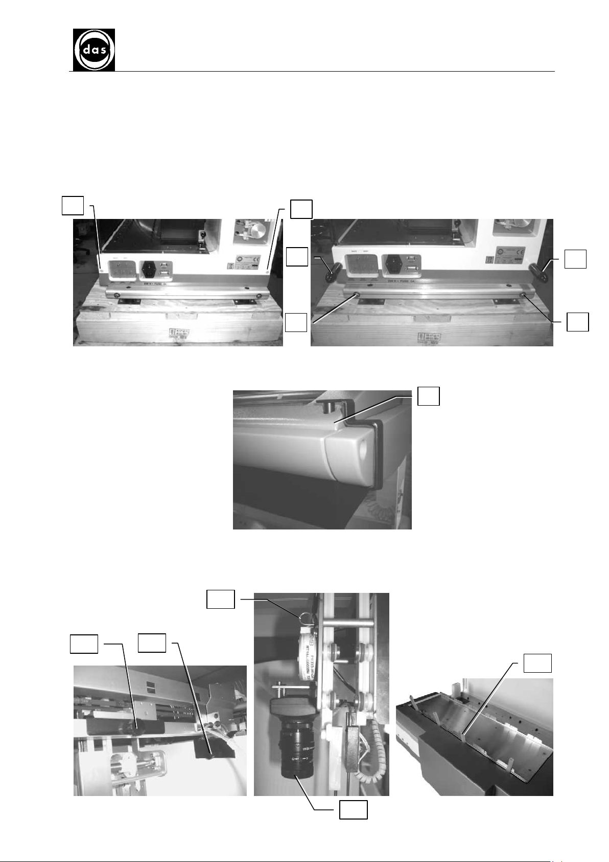
2.1. INSTALLATION
The instrument is packed with a wooden box. To unpack the instrument follow the instructions described below:
a) Remove the 2 plastic covers (1-2) from the instrument right side and the other ones from the left side. Screw
in the 4 handles on both sides (3-4) for manual instrument placement. Once in position remove the handles e
put back in place the plastic covers.
b) Remove the 4 screws that hold the instrument on to the wood base (5-6)
c) Remove screw and bracket (7), screw in the same place using the screw removed before
d) Remove,.- screw and bracket (7), screw in the same place the enclosed screw in the bag
e) Remove screws (8,9,10) and related brackets
f) Remove the Z block holder (11) as indicated
g) Remove the protection cap from the camera (12)
h) Remove the blocking tools (13) from the oscillating plane
Page 16

2.2. WORK AREA
AP-Blot work area showing the various components:
Probe washing
basin
48 position Sample rack Reagent and control rack Tanks
AP Blot – SERVICE MANUAL
SECTION 2
INSTALLATION AND TECHNICAL SPECIFICATIONS
Doc. N° MDS-AP-26-00-02
Rev.01
Date: 02.04.2009
Pag. 16
Camera Calibration area Strip holder rack
Fig. 1 - AP-Blot Work Area
2.3. TECHNICAL SPECIFICATIONS
Sample rack
Reagent rack
Liquid Containers
Strip Holders
Dispensation System
Strip Washing
Image acquisition system
Dispensation
Software
Minimum PC Requirements
Power Requirements
Optional
Measurements
Weight
48 sample tubes (Ø 13mm)
6 x 100ml vials and 8 control positions
2 tanks for wash buffer and waste. Both with liquid level sensors
6 slides (8 strips per slide) to process up to strips on oscillating plane
1 dispensation and 1 aspiration probe
Liquid dispensation and aspiration via two instrument probes
High Resolution Colour Camera (3.3 Megapixels) mounted above Probes
Up to 2500 µl with a 1 µl resolution
Windows 2000 and XP compatible to set up work list, reports and result archive.
Loading work lists and transmit results via Host Computer interface (LIS)
− 200 MB free hard disk space
− CD-Rom reader
− RAM 512 MB
− Pentium 4
− Standard video card:VGA 1024x768 16 million colours
− Free USB 2.0 port
230/115 VAC, 50-60Hz, 150W
Bar Code Reader (BCR) for samples with position ID
79 x 61 x 65 h (in cm)
71 Kg
Page 17

AP Blot - SERVICE MANUAL
SECTION 3
MAINTENANCE PROCEDURES
Doc. N° MDS-AP-26-00-02
Rev.01
Date: 02.04.2009
Page 17
SECTION 3
MAINTENANCE PROCEDURES
Page 18

Page 19
CAMERA
AP Blot - SERVICE MANUAL
SECTION 3
MAINTENANCE PROCEDURES
Doc. N° MDS-AP-26-00-02
Rev.01
Date: 02.04.2009
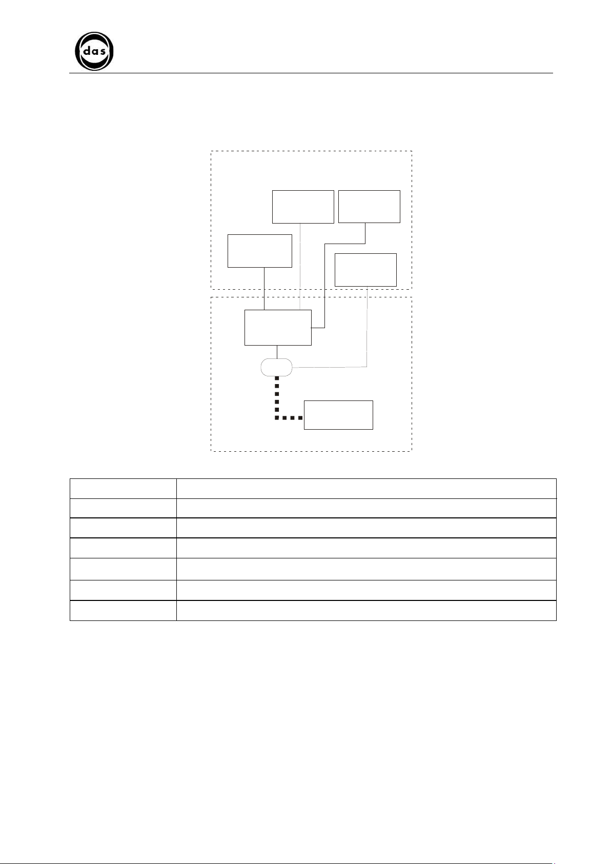
3.1 SYSTEM ARCHITECTURE
The system architecture is illustrated in the following diagram and described in table below:
Function group
Page 19
Control and check board
Functional unit Description
X-Y AXIS
Z1, Z2 AXIS
DILAP21
USB
DILUTOR
UNIT
SHAKING PLANE
Personal
Computer
X – Y Axis
Z1 Axis
Z2 Axis
Dilutor unit
Shaking Plane
Camera
The X-Y axis movement mechanism moves probe arms over work area with precision
The Z1 axis raises and lowers dispensing probe over work area.
The Z2 axis raises and lowers aspiration probe over work area.
The dilutor unit aspirates and dispenses samples, calibrators, controls, and generally all
reagents. It also washes Z1 axis probe internally and externally.
The shaking plane shakes the 6 slides holding the strips to be processed
The camera acquires the images of the processed strips.
Page 20

The AP Blot communicates with the PC via a serial connection: between the Dilutor PCB and the PC.
The units controlled by the PCB are:
AP Blot - SERVICE MANUAL
SECTION 3
MAINTENANCE PROCEDURES
PCB Unit
X – Y Axis
Z1 – Z2 Axis
DILAP21
Dilutor unit
Shaking plane
Doc. N° MDS-AP-26-00-02
Rev.01
Date: 02.04.2009
Page 20
Page 21
AP Blot - SERVICE MANUAL
SECTION 3
MAINTENANCE PROCEDURES
Doc. N° MDS-AP-26-00-02
Rev.01
Date: 02.04.2009
3.2 REMOVING WORK AREA
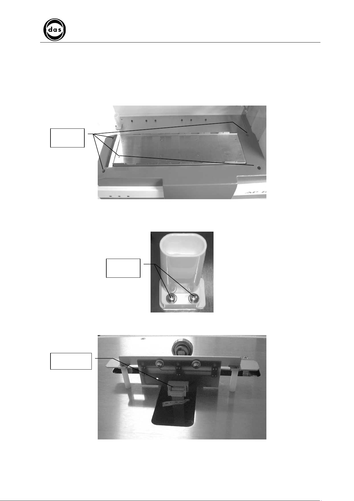
3.2.1. REMOVING WORK AREA
a) Turn off instrument
b) To remove strip holder tray plate first loosen four screws holding shaking plane
4 fixing
screws
Page 21
c) Remove 2 fixing screws from Probe wash basin and detach Waste (“OUT”) tube from under basin
2 fixing
screws
d) Remove connector from shaking plane positioning opto PCB (OP-Swing PCB)
1 connector
Page 22
AP Blot - SERVICE MANUAL
SECTION 3
MAINTENANCE PROCEDURES
Doc. N° MDS-AP-26-00-02
Rev.01
Date: 02.04.2009
Page 22
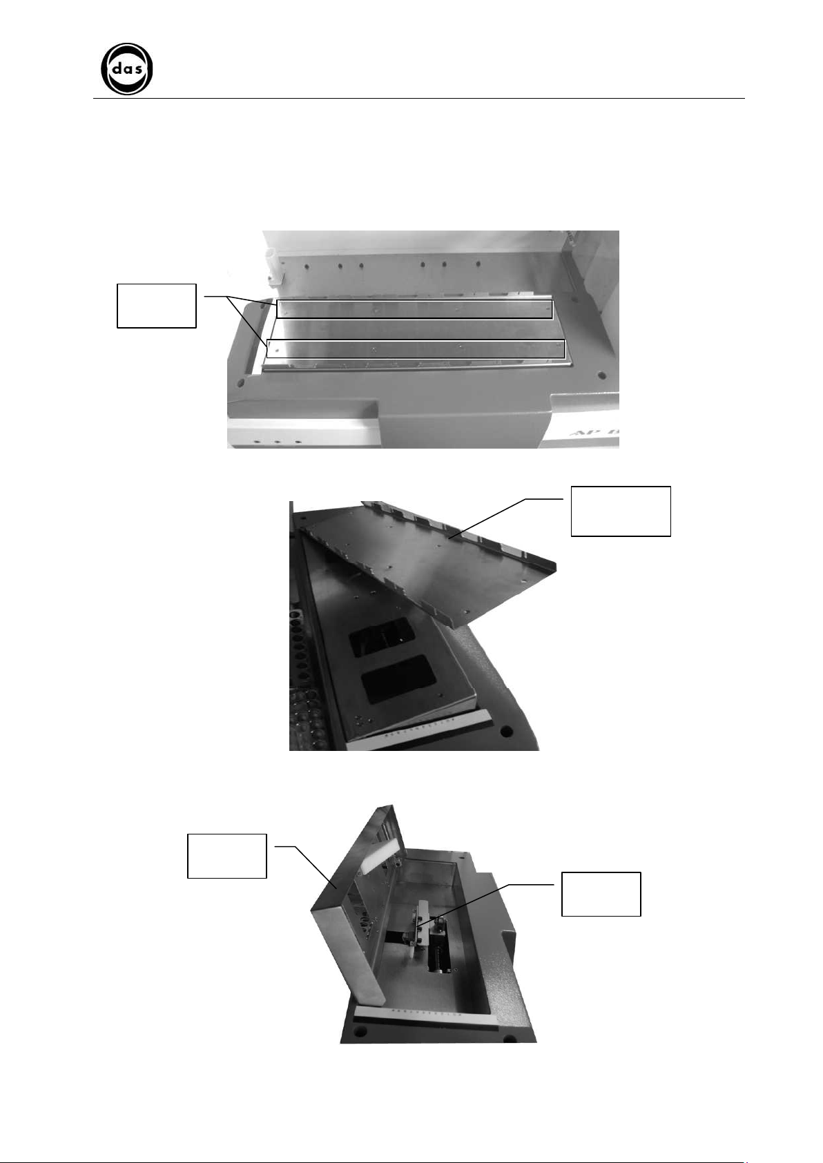
e) Remove 8 screws from bottle separation carter
f) Remove 7 screws from aluminium shaking plane
Bottle separation
carter
Aluminium
shaking plane
g) Lift up and detach screws holding the shaking plane movement mechanism motor
h) NB: each time shaking plane support is moved, or removed calibrate shaking plane as described Para. 4.8.4.
Page 23
AP Blot - SERVICE MANUAL
SECTION 3
MAINTENANCE PROCEDURES
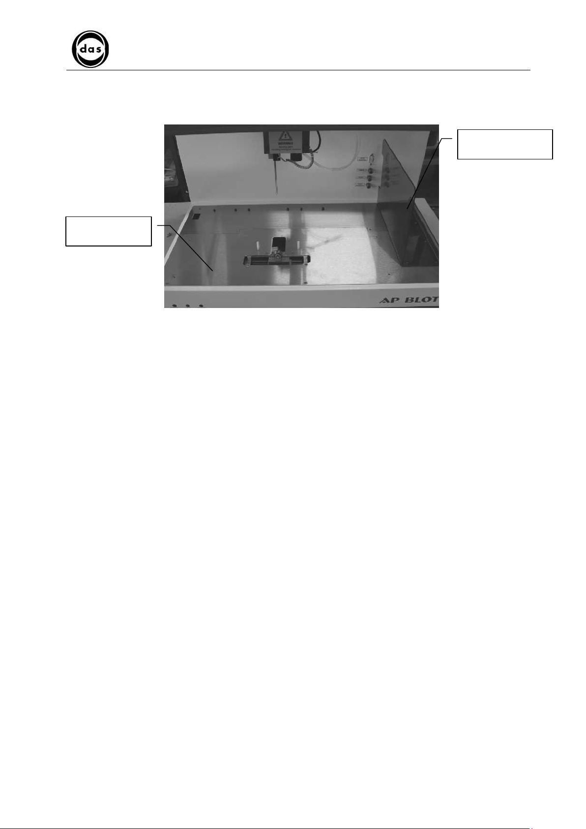
3.2.2. Removing shaking plane
a) Turn off device
b) Remove 8 screws from strip holder tray plate.
8 fixing
screws
c) Remove strip holder tray plate
Doc. N° MDS-AP-26-00-02
Rev.01
Date: 02.04.2009
strip holder
tray plate
Page 23
d) Lift up shaking plane
Shaking
plane
OP-Swing
PCB
Page 24
AP Blot - SERVICE MANUAL
SECTION 3
MAINTENANCE PROCEDURES
3.3 DILUTOR UNIT
3.3.1. DESCRIPTION OF HOW IT WORKS
FUNCTION
The dilutor unit aspirates and dispenses samples, calibrators, controls and all reagents, and also cleans
inside of Z1 probe.
3.3.1.1. Dilutor Unit
Doc. N° MDS-AP-26-00-02
Rev.01
Date: 02.04.2009
Page 24
SIDILOP
PCB
Syringe
Dilutor
movement
mechanism
Valve support
INTERFA2
PCB
Electro-valve
The DILUTOR UNIT is composed of following parts (clockwise direction):
1 Dilutor mechanism
2
3 Syringe
2-way Electro-valve For the aspiration of washing solution or for probe aspiration/dispensation
Moves probe with step motor
To aspirate and dispense
Page 25
Dilutor unit
4
5
AP Blot - SERVICE MANUAL
SECTION 3
MAINTENANCE PROCEDURES
Doc. N° MDS-AP-26-00-02
Rev.01
Date: 02.04.2009
Page 25
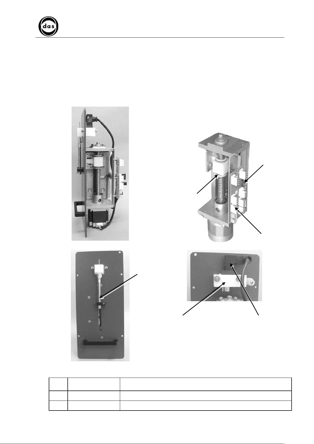
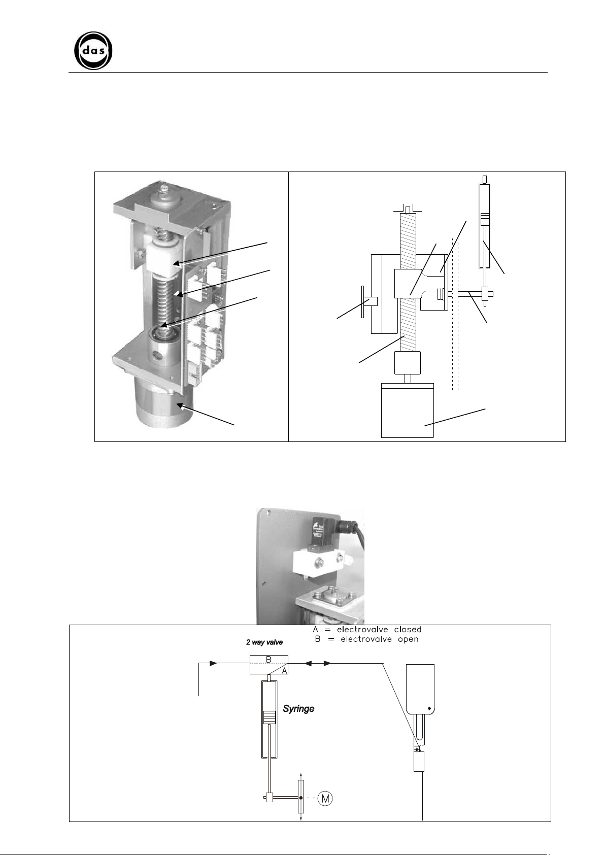
3.3.1.2. Dilutor mechanism
This mechanism moves the syringe plunger (1) up and down in small steps. The movement is generated by a step
motor (2) which moves a special worm screw (3) inside a female plastic nut 4) fixed on a carriage (5) which runs along
a track (6) on 4 ball bearings. A shaft is mounted on the carriage (7) which then moves the syringe plunger (1). The
optic sensor (8) is mounted on the SIDILOP PCB and signals when the syringe plunger has reached the End line
(“home”) position.
4
6
1
3
8
7
3
2
2
3.3.1.3. Valve mechanism/Syringe
The valve mechanism connects the Wash bottle to the rest of the hydraulic syringe-probe circuit through the peristaltic
pump.
The syringe movement is generated by the dilutor unit and the syringe is connected to the dispensing probe
Page 26
MAINTENANCE PROCEDURES
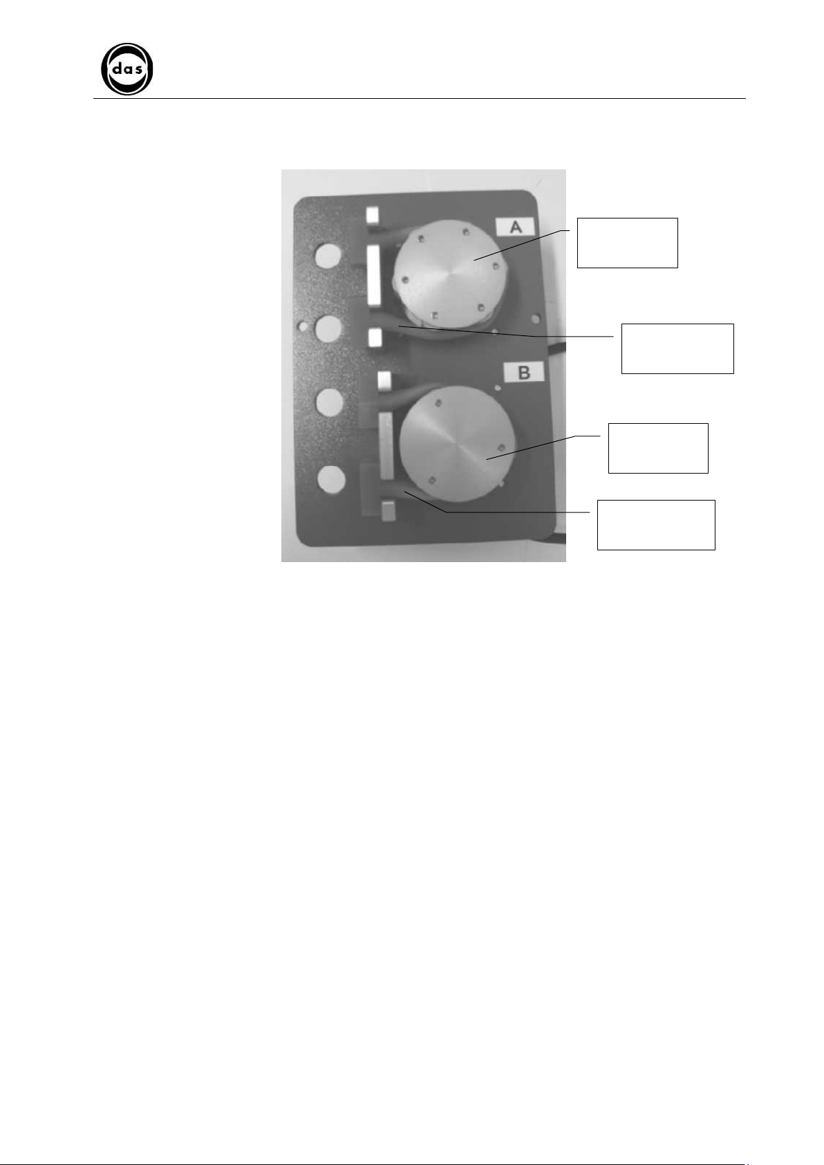
3.3.1.4. Pump Unit
AP Blot - SERVICE MANUAL
SECTION 3
Doc. N° MDS-AP-26-00-02
Rev.01
Date: 02.04.2009
Peristaltic
pump A
Page 26
Peristaltic pump
tubing
Peristaltic
pump B
Peristaltic pump
tubing
The pump unit is made up of 2 peristaltic pumps composed of:
- rotating wheel
- stand
- peristaltic pump tubing
- step motor
Note:
• Pump A washes dispensation probe internally and externally and regulates WASH liquid flow during STRIP
WASH phase.
Page 27
Groud
Liquid level
Microprocessor
Impulse duration T
AP Blot - SERVICE MANUAL
SECTION 3
MAINTENANCE PROCEDURES
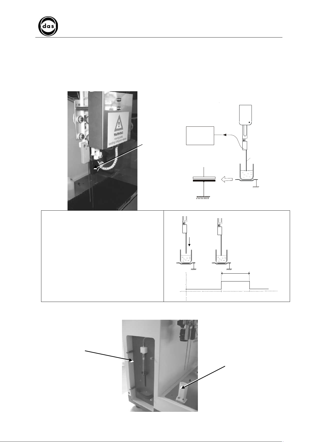
3.3.1.5. Probe
The probe has two functions:
• Liquid aspiration and dispensation
• Liquid sensor (for liquid level)
Aspiration and dispensation
The probe aspirates and dispenses controls, samples, etc.
Doc. N° MDS-AP-26-00-02
Rev.01
Date: 02.04.2009
Page 27
Aspiration
Probe
Liquid Sensor
The probe is fitted with a liquid sensor which regulates
its movements near the liquid to be aspired.
This sensor reads the variations of the electrical capacity
of the circuit which consists of probe – liquid – ground.
The sensor circuit emits a low signal (level 0) until the
probe touches the liquid.
A high signal (level 1) is emitted to indicate when the
probe touches the liquid for duration ‘T’ in proportion to
the variation of the circuit capacity.
Adjusting probe sensitivity is based on the
duration/bandwidth of this impulse. (Below a certain
value this impulse is only considered noise and not valid
as a liquid surface signal).
sensor
Probe
3.3.1.6. Probe Wash Basin
The probe wash basin is used for external probe washing and to dispose of liquid excess.
Dilutor unit
Probe washing
basin
Page 28
AP Blot - SERVICE MANUAL
SECTION 3
MAINTENANCE PROCEDURES
Doc. N° MDS-AP-26-00-02
Rev.01
Date: 02.04.2009
Page 28
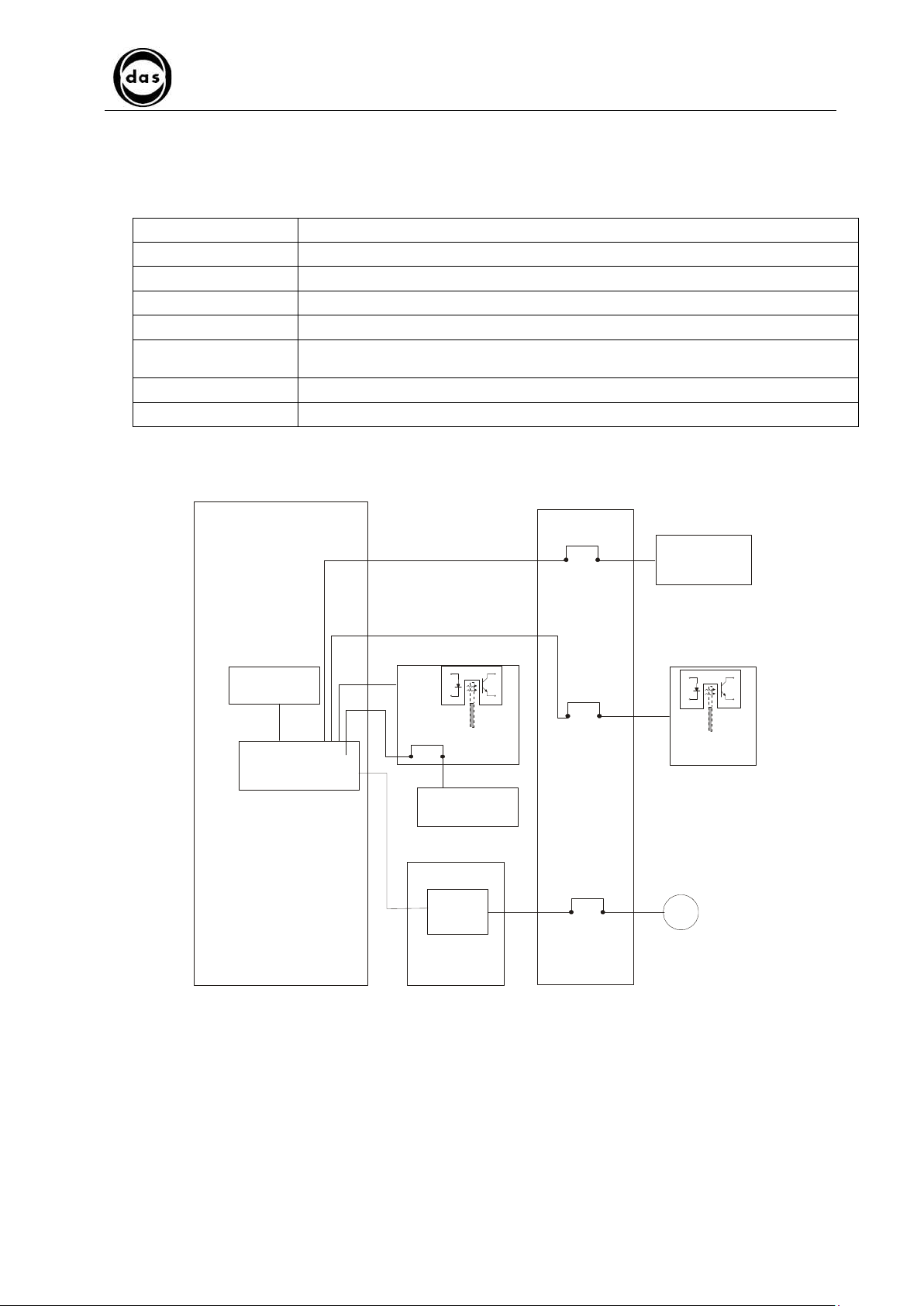
3.3.1.7. Dilutor Unit PCB Electrical Diagram
The table below describes each PCB and the various dilutor unit components they control and the diagram shows the
PCBs and the dilutor unit electrical circuit.
DILAP21 (Dilutor) PCB a micro-processor, a memory and electro-valve driver
SIR4MOT PCB syringe motor driver.
SIDILOP PCB optical sensor which senses when syringe has reached end line (“home”) position.
INTEROP2 PCB Support for liquid level sensor and cable distribution
INTERFA2 PCB Connects wire cables
Liquid Level Sensor Electronic circuit in a small container mounted on probe which signals contact with liquid surface
Syringe Motor A step motor which moves syringe plunger (with special “worm” screw inside the plastic nut).
Dilutor 2-way Electro-valve Manages washing solution aspiration or probe aspiration/dispensation.
(level)
Memory
Microprocessor
DILAP21 PCB
INTEROP2
PCB
Liquid Level
Sensor
Syringe
motor
driver
SIR4MOT
PCB
INTERFA2
PCB
2 way
electrovalve
SIDILOP
PCB
M
Syringe motor
Page 29
Dis pens ation probe
Aspir ation pr obe
AP Blot - SERVICE MANUAL
SECTION 3
MAINTENANCE PROCEDURES
Doc. N° MDS-AP-26-00-02
Rev.01
Date: 02.04.2009
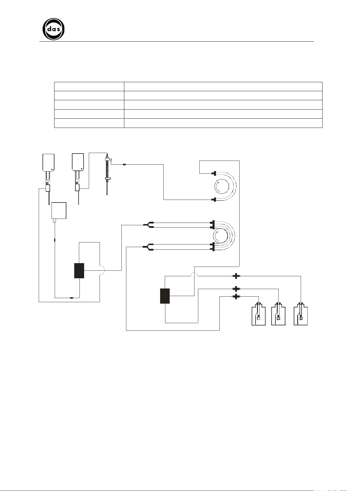
3.3.1.8. Dilutor unit hydraulic component diagram
The table below describes the different functions of the dilutor unit hydraulic components.
The diagram shows how the dilutor unit circuit is set up to work.
WASH bottle Contains probe-washing liquid, 5 litre capacity
Level Sensor Sensor for the three different bottles and connecting cables and connectors
Probe washing pump Peristaltic pump A for washing probe, internally and externally, driven by step motor
Probe wash basin For external probe wash and draining any excess liquid
Syringe For aspirating and dispensing liquid through probe
Page 29
3 way
Electro valve
Syringe
Needle washing basin
3 way E lectrovalve
Peristaltic P um p A
Peristaltic P ump B
WA SH
WA SH BU FFE R
WA STE
WA STE bottle
WA SH BU FFE R
bottle
WA SH bottle
Page 30

AP Blot - SERVICE MANUAL
SECTION 3
MAINTENANCE PROCEDURES
3.3.2. REGULAR DILUTOR UNIT MAINTENANCE
Visually check the following components:
− Tubing connecting Valve – Probe.
− Syringe plunger
Doc. N° MDS-AP-26-00-02
Rev.01
Date: 02.04.2009
Page 30
1
3.3.2.1. Visual checks
• Tubing connecting Valve – Probe:
Check that there is no narrowing or kinks or obstructions on any of this tubing.
If these faults are found the tubing can be substituted as described in para. 3.3.3.1.
• Syringe plunger:
Check that the syringe plunger and tip are in good condition (they should be clean and without any liquid dripping
from syringe bottom).
If condition is unsatisfactory, substitute plunger following procedure described in para. 4.8.5.
• Syringe:
Check that syringe glass is in good condition. If any damage can be seen then substitute syringe following procedure
described in paragraph 4.8.5.
• Peristaltic pump tubing:
Check that tubing is in good condition and more specifically check that there are no traces of rubber around pump
area. If condition or area is unsatisfactory change this rubber tubing as described in para. 3.3.3.5.
• Shaking plane:
Check that shaking movement is smooth, with no obstructions or hesitations. If movement is unsatisfactory check
shaking mechanism as described in Para. 3.6.1.1.
• Camera Calibration strip:
Check that camera calibration strip is clean and intact. If condition is unsatisfactory, clean off strip with a clean cloth
and/or substitute strip.
• Camera:
Check that electrical cable is correctly plugged in
− Syringe
Every 4 months Ref. para. 3.3.2.1.
− Peristaltic Pump tubing
− Shaking plane
− Calibration Strip
− Camera
Page 31

AP Blot - SERVICE MANUAL
SECTION 3
MAINTENANCE PROCEDURES
Doc. N° MDS-AP-26-00-02
Rev.01
Date: 02.04.2009
3.3.3. SUBSTITUTING DILUTOR UNIT COMPONENTS
To substitute syringe and syringe plunger refer to para. 4.8.5.
The following table lists procedures and paragraphs relevant to these substitutions.
Substituting valve – syringe – dispensation probe tubing Ref. para. 3.3.3.1
Substituting valve mechanism Ref. para. 3.3.3.2
Substituting 3-way Electro valve Ref. para. 3.3.3.3
Substituting 3-way valve mechanism Ref. para. 3.3.3.4
Substituting Peristaltic Pump Tubing Ref. para. 3.3.3.5
Substituting Dilutor Motor Ref. para. 3.3.3.6
Substituting Opto SIDILOP PCB Ref. para. 3.3.3.7
Substituting INTERFA2 PCB Ref. para. 3.3.3.8
Substituting probe wash basin Ref. para. 3.3.3.9
Page 31
3.3.3.1. Substituting valve – syringe – dispensation probe tubing
a) Disconnect AWG15 tubing from probe
AWG15
tubing
b) The old tubing (to be replaced) should be used as a guide or ‘driver’/track
c) Join the ends of the old and new tubing together with adhesive tape.
d) Slowly pull old tubing.
e) Separate new tubing from the original “driver” tubing and join the new tubing to the valve unit joint and probe.
Page 32

AP Blot - SERVICE MANUAL
SECTION 3
MAINTENANCE PROCEDURES
Doc. N° MDS-AP-26-00-02
Rev.01
Date: 02.04.2009
Page 32
3.3.3.2. Substituting valve mechanism
a) Turn on instrument. Run XCalib Program (See Section 4). From “Dilutor” pulldown menu select “Calibrate
syringe” and follow instructions.
b) Click on “Remove syringe” to fully open syringe plunger.
c) Turn off machine
d) Remove AWG 15 tubing from valve joint
e) Unscrew syringe from valve mechanism in an anti-clockwise direction and extract it
f) Remove tubing joined to valve mechanism
g) Remove valve connector by undoing fixing screw
Hexagonal head
Connector/
Electro-valve
fixing screw
Valve mechanism
tubing join
h) Remove valve mechanism by undoing 2 fixing nuts
i) Insert new valve mechanism and re-block it with 2 fixing nuts.
j) Replace valve and connector
k) Replace hydraulic connections
l) Replace syringe in movement shaft and screw it back into valve mechanism in a clockwise direction.
m) Turn on instrument again and run a prime to rinse hydraulic circuit
3.3.3.3. Substituting 3-way Electro valve
Note: to replace electro valve follow procedure described in para. 3.11.2.1.
3.3.3.4. Substituting 3-way valve mechanism
Note: to replace valve mechanism follow procedure described in para.3.11.2.1.
Page 33

B
A
3.3.3.5. Substituting Peristaltic Pump Tubing
a) Turn on instrument. Run XCalib program. From “Dilutor” menu select “Prime”
b) Detach wash loading and buffer tubing from their bottles
c) Set prime for at least 60 seconds to empty hydraulic circuit. Select ‘Prime’
d) After this prime rinse, detach tubing and then slip tubing off pumps.
AP Blot - SERVICE MANUAL
SECTION 3
MAINTENANCE PROCEDURES
Peristaltic pump tubing
White / Black
Doc. N° MDS-AP-26-00-02
Rev.01
Date: 02.04.2009
Page 33
Blue / White
e) Place new peristaltic tubing into position and re-connect it up following the diagram sticker on device.
f) Reconnect both Wash loading and Buffer tubing to their respective bottles.
g) Run another prime by selecting “Prime” option to rinse hydraulic circuits again
Page 34

AP Blot - SERVICE MANUAL
SECTION 3
MAINTENANCE PROCEDURES
3.3.3.6. Substituting Dilutor Motor
a) Remove AWG15 tubing.
b) Remove 4 screws from dilutor unit stand.
c) Remove connector that joins dilutor motor to INTERFA2 PCB
d) Loosen two grub screws that block motor axis mechanism .
Doc. N° MDS-AP-26-00-02
Rev.01
Date: 02.04.2009
Page 34
two grub screws
e) Remove the motor by loosening the 4 fixing screws
4 syringe motor
fixing screws
f) Re-position new motor and block it in position with 4 motor fixing screws and tighten grub screws that were
previously loosened (in step ‘d’)
g) Restore motor and INTERFA2 – PCB connections.
Page 35

AP Blot - SERVICE MANUAL
SECTION 3
MAINTENANCE PROCEDURES
Doc. N° MDS-AP-26-00-02
Rev.01
Date: 02.04.2009
3.3.3.7. Substituting Opto SIDILOP PCB
a) Remove AWG15 tubing.
b) Remove 4 screws from dilutor panel.
c) Remove connector between SIDILOP PCB and INTERFA2 PCB.
d) Unscrew fixing screws.
e) Re-position new PCB and attach it with fixing screws
f) Re-connect new SIDILOP and INTERFA2 PCB.
3.3.3.8. Substituting INTERFA2 PCB
a) Remove AWG15 tubing.
b) Remove 4 screws from dilutor panel.
c) Remove connectors from INTERFA2 PCB and two screws attaching it to the plate.
d) Substitute PCB and re-attach it with the 2 screws; follow numbering to re-position connectors correctly.
e) Replace dilutor unit in position.
3.3.3.9. Substituting probe wash basin
a) Unscrew probe wash basin from work area.
Page 35
b) Lift up basin and disconnect Waste (“OUT”) tubing
c) Substitute probe wash basin
d) Reconnect “OUT” tubing to probe wash basin .
e) Replace basin on work area with screws removed previously and proceed to centering procedure for probe 1 as
described in para. 4.8.1
Page 36

AP Blot - SERVICE MANUAL
SECTION 3
MAINTENANCE PROCEDURES
Doc. N° MDS-AP-26-00-02
Rev.01
Date: 02.04.2009
3.4. X–Y AXIS
3.4.1. DESCRIPTION OF HOW IT WORKS
3.4.1.1. X – Y axis movement mechanism
FUNCTION:
The X – Y axis movement mechanism moves probe arm precisely over work area.
Page 36
The X axis movement mechanism moves the X axis carriage (1). The Y axis is fastened on the carriage (2). The
movement is generated by a motor (3) and a pulley (4), a serrated belt (5) and an idle wheel (6). The XGOLAV
opto PCB is mounted on the X axis carriage (1). The encoder (7) controls the position along X-axis through
encoder slits.
3
5
4
7
The Y axis mechanism moves carriage along Y Axis (1) on which the Z1 and Z2 axis are fixed. The movement is
generated by step motor (2) with a serrated belt (3) and an idle wheel (4). The INTEROP2 PCB (5) is mounted on
the Y Axis carriage (1). The encoder (6) controls the position along Y-axis through the encoder slits.
4
1
6
1-2
2
6
5
Page 37

X axis motor
Y axis motor
3.4.1.2. X- Y axis Electrical Functions Diagram
The table below describes the electrical components of each PCB which effects the movement of the X-Y axis.
The arrangement is shown in the diagram.
DILAP21 PCB Microprocessor and memory.
SIR4MOT PCB Controls X - Y axis.
XGOLAV “X” PCB Controls opto with which the encoder controls axis position.
INTEROP2 ”Y” PCB
Opto couplers
INTERFA1 PCB Connectors for wiring.
INTERFA2 PCB Connectors for wiring.
AP22MOT PCB Connectors for wiring.
X axis motor Step motor
Y axis motor Step motor
AP Blot - SERVICE MANUAL
SECTION 3
MAINTENANCE PROCEDURES
The Opto couplers, together with the selectors, control:
1) Y probe position
2) Z1 and Z2 probes position
3) ZZ probe position
Doc. N° MDS-AP-26-00-02
Rev.01
Date: 02.04.2009
Page 37
INTEROP2 “Y”
PCB
Memory
M
INTERFA2
PCB
XGOLAV “X”
Microprocessor
PCB
X axis
motor
driver
M
Y axis
motor
driver
DILAP21 PCB
SIR4MOT
PCB
PCB
INTERFA1
AP22MOT
PCB
Page 38

AP Blot - SERVICE MANUAL
SECTION 3
MAINTENANCE PROCEDURES
Doc. N° MDS-AP-26-00-02
Rev.01
Date: 02.04.2009
Page 38
3.4.2. REGULAR MAINTENANCE FOR X–Y AXIS
Cleaning X-Y axis tracks Every 6 months Ref. para. 3.4.2.1
Check belt tension Every 6 months Ref. para. 3.4.2.2
Check condition of flat cables Every 6 months Ref. para. 3.4.2.3
3.4.2.1. Cleaning X-Y axis tracks
a) Use a sponge/clean cloth to wipe dust off and clean up any other dirty residue.
b) Uniformly spread the grease along the tracks with the same slightly damp sponge/cloth.
3.4.2.2. Check belt tension
a) If there is an excessive vibration when X and Y axis moves, then adjust the tension of the belts (Ref. Para.
3.4.3.1.).
b) If X and Y axis block during their movement check that belts are not too tight (Ref. Para. 3.4.3.1.).
3.4.2.3. Check condition of flat cables
a) Check that flat cables are not touching any metal parts.
b) Check that cables maintain their original folds.
3.4.3. CALIBRATING X–Y AXIS SETTINGS
To center X-Y-axis refer to para. 4.8.1.
The following table lists the relevant paragraphs describing the different possible calibrations
Errore. L'origine riferimento non è stata trovata.
Every 6 months Ref. para. 4.8.1.2
X and Y axis belt tension Every 6 months Ref. para. 3.4.3.1
3.4.3.1. X and Y axis belt tension
a) Regulate X axis belt tension by turning idle wheel.
b) Regulate Y axis belt tension by loosening the fixing screws from the Y axis motor, move the motor along in the Y
direction until the belt has reached the correct tension
c) Once the correct tension has been achieved, tighten the fixing screws.
X-Axis idle wheel
Y-Axis motor
Page 39

AP Blot - SERVICE MANUAL
SECTION 3
MAINTENANCE PROCEDURES
Doc. N° MDS-AP-26-00-02
Rev.01
Date: 02.04.2009
3.4.4. Substituting X–Y AXIS PARTS
Substituting X-axis Movement Motor Ref. para. 3.4.4.1
Substituting Y-axis Movement Probe motor Ref. para. 3.4.4.2
Substituting Opto XGOLAV (X-axis movement) Ref. para. 3.4.4.3
Substituting X-axis movement belt Ref. para. 3.4.4.4
Substituting Flat Cables Ref. para. 3.4.4.5
Substituting X-Y axis movement flat cables Ref. para. 3.4.4.6
Substituting INTEROP2 PCB (Y-axis movement) Ref. para. 3.4.4.7
3.4.4.1. Substituting X-axis Movement Motor
a) Remove protective cover from device by loosening the screws on top.
b) Remove motor connector from INTERFA2 PCB.
c) Loosen 2 dowels on wheel which sustains the belt.
Page 39
2 dowels
d) Remove motor by loosening 4 fixing screws.
4 fixing
screws.
e) Position new motor, and secure it by tightening the 2 dowels.
f) Reconnect connector to INTERFA2 PCB.
g) Replace cover.
Page 40

AP Blot - SERVICE MANUAL
SECTION 3
MAINTENANCE PROCEDURES
3.4.4.2. Substituting Y-axis Movement Probe Motor
a) Remove top cover by undoing screws on top of device.
b) Remove connector which joins motor to AP22MOT PCB
c) Remove motor after loosening 4 fixing screws.
Doc. N° MDS-AP-26-00-02
Rev.01
Date: 02.04.2009
4 fixing
screws
Page 40
d) Place new motor in position and fix in place with 4 screws.
e) Check belt tension.
f) Reconnect motor to AP22MOT PCB with connector
3.4.4.3. Substituting Opto XGOLAV (X-axis movement) PCB
a) Remove top cover after undoing screws on top.
b) Remove connector attached to XGOLAV PCB.
c) To substitute it unscrew PCB from plate.
XGOLAV
PCB
2 fixing
screws
d) Place new PCB in position and screw it to the plate with two fixing screws
e) Re-insert connector onto PCB.
f) Check centering of X axis (see para. 4.8)
g) Replace top cover.
Page 41

AP Blot - SERVICE MANUAL
SECTION 3
MAINTENANCE PROCEDURES
Doc. N° MDS-AP-26-00-02
Rev.01
Date: 02.04.2009
3.4.4.4. Substituting X-axis movement belt
a) Remove screws fixing instrument cover to remove cover.
b) Loosen 3 grub screws fixing both ends of belt.
c) Replace belt and then tighten 3 grub screws which fixed the 2 ends of belt.
d) Check that belt is correctly tightened.
e) Remount cover
3.4.4.5. Substituting Flat Cables
a) The flat cables are held in position by plastic cable holder bands.
cable holder
bands
Page 41
b) Remove PCB connectors 6
c) Remove cable holder bands and gently pull out flat cable.
d) Insert new flat cable and replace all previous cable holder bands.
e) Carefully re-insert connectors in correct positions.
3.4.4.6. Substituting X-Y axis movement flat cables
a) Remove device top cover after undoing top screws
b) Remove connectors between Y axis motor and AP22MOT PCB
c) Remove all plastic cable holder bands.
d) Remove cable blocking plates PIASTRINE CHE BLOCCANO I CAVI DI MOVIMENTO
e) Dismount INTERFA1 PCB from base of frame
f) Remove black blocking plate and then undo 2 fixing screws from AP22MOT PCB
g) After removing all remaining protection - replace chain with AP22MOT and INTERFA1 PCBs on each end
h) Remount new cable with PCBs and reposition all cable holder bands
i) Remount cover
AP22MOT PCB
X-Y-axis
movement flat
Cable blocking
Plate
INTERFA1 PCB
Cable blocking
Plate
Page 42

3.4.4.7. Substituting INTEROP2 PCB (Y-axis movement)
a) Undo fixing screws to remove device top cover
b) Detach connectors from INTEROP2 PCB and remove 4 fixing screws.
2 fixing screws
AP Blot - SERVICE MANUAL
SECTION 3
MAINTENANCE PROCEDURES
Doc. N° MDS-AP-26-00-02
Rev.01
Date: 02.04.2009
Page 42
2 fixing screws
c) Reposition new PCB and secure it with 4 fixing screws.
d) Reinsert connectors.
e) Check Y-axis centering
f) Check Z maximum value.
g) Reposition cover and screw back screws
Page 43

Asse Z
2
1
2
3
4
4
1
2
3
AP Blot - SERVICE MANUAL
SECTION 3
MAINTENANCE PROCEDURES
Doc. N° MDS-AP-26-00-02
Rev.01
Date: 02.04.2009
Page 43
3.5. Z1 - Z2 AXIS
3.5.1. DESCRIPTION OF HOW IT WORKS
3.5.1.1. Z1 - Z2 axis movement mechanism
FUNCTION OF Z1 AXIS (dispensation)
Z1 Axis moves the dispensation probe up and down over the instrument work area. This movement is driven by a step
motor (1) with a pinion mounted on its shaft (2) that transmits the movement to the carriage (3).
The optical sensor, by means of the carriage encoder (4), detects the probe End line (“home”) position.
FUNCTION OF Z2 AXIS (aspiration)
Z2 Axis moves the aspiration probe up and down over work area.
The movement is driven by a step motor (1) with a pinion mounted on its shaft (2) that transmits the movement to the
carriage (3).
The optical sensor, by means of the carriage encoder (4) detects probe home position.
The camera is mounted on back plate and is used to acquire images.
Asse Z
1
Page 44

DILAP21 PCB
INTEROP2 PCB
Microprocessor
M
Z2 Axis motor
M
Z1 Axis motor
3.5.1.2. Z axis electrical circuit diagram
The diagram shows the different electronic functions with the relevant PCBs for the Z axis, followed by a brief
description and the following table lists the various PCBs and their components.
DILAP21 PCB Contains the microprocessor, memory and Z-axis motor drivers
INTEROP2 PCB Contains optical sensor to detect probe end line run (“home”) position.
Z1 – Z2 axis motor Step motor which moves Z1 – Z2 axis probes
AP Blot - SERVICE MANUAL
SECTION 3
MAINTENANCE PROCEDURES
Doc. N° MDS-AP-26-00-02
Rev.01
Date: 02.04.2009
Page 44
Liquid
Memory
sensors
Z
Axis
1
motor
driver
Z Axis
2
motor
driver
Page 45

AP Blot - SERVICE MANUAL
SECTION 3
MAINTENANCE PROCEDURES
Doc. N° MDS-AP-26-00-02
Rev.01
Date: 02.04.2009
Page 45
3.5.2. REGULAR Z AXIS MAINTENANCE
3.5.2.1. Z2 axis movement control
a) Turn on device and run XCalib programme. From “Dilutor” pulldown menu select “Calibrate height” then select a
strip holder plate and select probe 1, Select “Go down” option
b) Check that movements are smooth and linear
c) Repeat movement control also on probe 2.
d) If movements are not smooth or/and linear check pinion or carriage and replace parts if necessary
e) If any parts are substituted verify movements as in point (b)
3.5.3. Z-AXIS CALIBRATION
To calibrate Z-axis refer to para. 4.8.
The following table lists the relevant paragraphs describing different possible calibrations
Calibrate probe height Para. 4.8.2
Calibrate LT Para. 4.8.3
Calibrate SUL Para. 4.8.6
Page 46

AP Blot - SERVICE MANUAL
SECTION 3
MAINTENANCE PROCEDURES
Doc. N° MDS-AP-26-00-02
Rev.01
Date: 02.04.2009
3.5.4. SUBSTITUTING Z1 and Z2 AXIS PARTS
Substituting Z1 Axis probe Para. 3.5.4.1
Substituting Z1 Axis probe motor Para. 3.5.4.2
Substituting Z2 Axis probe Para. 3.5.4.3
Substituting Z2 Axis probe motor Para. 3.5.4.4
3.5.4.1. Substituting Z1 Axis probe
a) Remove instrument cover
b) Remove protective carter by unscrewing two fixing screws
Page 46
2 fixing
screws
c) Detach AWG15 tubing from Probe
d) Remove liquid sensor cable connector from INTEROP2 PCB
e) Remove screw that fixes probe to stand
fixing screw
f) Replace probe with new probe and tighten fixing screw
g) Reconnect probe and liquid sensor connector (NON CE SU VERSIONE ITaliana) to INTEROP2 PCB and
reposition AWG15 tubing to Probe
h) Check Z axis settings: Z steps and LT parameter
i) Check X-Y centering
Page 47

AP Blot - SERVICE MANUAL
SECTION 3
MAINTENANCE PROCEDURES
Doc. N° MDS-AP-26-00-02
Rev.01
Date: 02.04.2009
3.5.4.2. Substituting Z1 Axis probe motor
a) Remove instrument cover
b) Remove Z1 axis protective carter by unscrewing two fixing screws
c) Remove motor connector from INTEROP2 PCB and remove cable holder bands
Motor fixing
screws
Page 47
d) Remove motor fixing screws
e) Replace motor and all connections between PCB and motor, re-position cable holder bands
f) Check that Z axis movements are smooth
g) Check Z1 axis steps
h) Check X-Y axis centering.
3.5.4.3. Substituting Z2 Axis probe
a) Remove silicon tubing connected to probe
b) Unscrew probe fixing screw
c) Replace probe and tighten fixing screw
d) Check centering of dispensation probe
e) Check distance between probes in home position (HH command with DIL PCB) is about 1 mm. If distance is
incorrect, remove instrument cover and adjust encoder on INTEROP2 PCB until probes are 1 mm distance
apart.
f) Check Z axis step setting .
Page 48

AP Blot - SERVICE MANUAL
SECTION 3
MAINTENANCE PROCEDURES
3.5.4.4. Substituting Z2 Axis probe motor
a) Remove Z1 protective carter after undoing two fixing screws
Doc. N° MDS-AP-26-00-02
Rev.01
Date: 02.04.2009
Page 48
2 fixing
screws
b) Remove motor connector from INTEROP2 PCB and remove cable holder bands
c) Remove fixing screws and change motor
Motor fixing
screws
d) Reconnect motor to PCB and replace cable holder bands
e) Check that Z2 axis movement is smooth.
f) Check Z1 movements and steps.
g) Check X-Y centering as described in para. 3.4.3.1.
Page 49

AP Blot - SERVICE MANUAL
SECTION 3
MAINTENANCE PROCEDURES
Doc. N° MDS-AP-26-00-02
Rev.01
Date: 02.04.2009
Page 49
3.6. SHAKING PLANE
3.6.1. DESCRIPTION OF HOW IT WORKS
3.6.1.1. Shaking plane movement mechanism
The shaking plane moves (shakes) the slides with the strips to be processed. The slides are placed on the ‘hinged’
shaking plane (1) and the movement is driven by a worm screw (2) on a ball-bearing (3) which moves along a wedge
(4) mounted under the shaking plane. The ball-bearing moves back and forth on the wedge generating the up and
down movement of the plane.
The minimum and maximum shaking excursion is controlled by 3 opto positioning sensors (5).
1
4
2
2 3
Page 50

M
Oscillating
(Flat position)
3.6.1.2. Shaking plane circuit diagram
The table lists the PCBs and the electrical components that move the Shaking plane.
This is followed by a diagram of the mechanism.
APE-IF-DIL-AP21 PCB Z1 and Z2 axis motor drivers
OP-SWING PCB Shaking plane optical sensors that control movement
Shaking plane Motor Step Motor that moves worm screw and ball bearing for shaking plane movement
AP Blot - SERVICE MANUAL
SECTION 3
MAINTENANCE PROCEDURES
Doc. N° MDS-AP-26-00-02
Rev.01
Date: 02.04.2009
Page 50
Down
Home
Up
OP-SWING PCB
Shaking
plane
motor
driver
plane
motor
INTERFA7 PCB
DILAP21 PCB
Page 51

AP Blot - SERVICE MANUAL
SECTION 3
MAINTENANCE PROCEDURES
Doc. N° MDS-AP-26-00-02
Rev.01
Date: 02.04.2009
3.6.2. MAINTENANCE AND SHAKING PLANE CALIBRATION
For calibration and maintenance of shaking plane refer to para. 4.8.4.
The following table lists the calibration procedures described in the relevant paragraphs.
3.6.3. SUBSTITUTING SHAKING PLANE COMPONENTS
Substituting Shaking Plane Motor Para. 3.6.3.1
Substituting opto PCBs Para. 3.6.3.2
3.6.3.1. Substituting Shaking Plane Motor
a) Remove aluminium work area as described in Para. 3.1.
b) Estrarre il piano di lavoro in alluminio
c) Loosen two nuts blocking motor axis.
Page 51
two nuts blocking
motor axis
d) Undo 4 fixing screws to remove motor
e) Position new motor, replace and tighten 4 fixing screws and nuts
f) Replace aluminium work area.
g) Proceed with calibrating shaking plane para 4.8.4.
4 fixing screws
Page 52

Connector
Fixing screws
AP Blot - SERVICE MANUAL
SECTION 3
MAINTENANCE PROCEDURES
Doc. N° MDS-AP-26-00-02
Rev.01
Date: 02.04.2009
3.6.3.2. Substituting opto PCBs
a) Remove work area as described in Para. 3.2.1.
b) Detach connector from Opto PCB to be substituted
c) Remove fixing screws to undo PCB
d) Reposition new PCB check that the Opto is not touching the encoder and replace the connector
e) Reposition work area
f) Calibrate shaking plane
Page 52
Page 53

AP Blot - SERVICE MANUAL
SECTION 3
MAINTENANCE PROCEDURES
Doc. N° MDS-AP-26-00-02
Rev.01
Date: 02.04.2009
Page 53
3.7. CAMERA
3.7.1. DESCRIPTION OF HOW IT WORKS
The camera is used to acquire digital images of each single strip. These images are then automatically elaborated
by the software and each single blot is analysed.
The camera is mounted on a stand (1) next to the probe unit.
The Optical Unit is made up of the camera (2) and lens (3).
The lens is screwed on the camera with a 5mm mount (4).
There are two rings with screw threads: one can be turned to focus (5) and the other (6) regulates the aperture.
For camera calibration see Para. 4.8.9
1
2
4
5
6
3
Page 54

AP Blot - SERVICE MANUAL
SECTION 3
MAINTENANCE PROCEDURES
Doc. N° MDS-AP-26-00-02
Rev.01
Date: 02.04.2009
Page 54
3.7.2. CAMERA MAINTENANCE
Check USB cable connection Para. 3.7.2.1
Lens cleaning Para. 3.7.2.2
3.7.2.1. Checking USB cable connection
a) Check that USB cable is correctly connected to the camera. When cable is correctly connected then check
that the camera is communicating with PC
b) Turn on device. Run XCalib program . From “Dilutor” menu select “Calibrate Camera” and check that images of
the work area are correctly being visualised by the camera and displayed.
3.7.2.2. Cleaning lens
a) Clean lens with a soft cloth lightly dampened with alcohol.
3.7.3. CALIBRATE CAMERA
To calibrate camera refer to para. 4.8.9.
The table below lists the calibration procedures described in the relevant paragraphs.
3.7.4. SUBSTITUTING CAMERA AND/OR PARTS
Substituting camera Para. 3.7.4.1
Substituting camera lens Para. 3.7.4.2
Substituting camera USB cable Para. 3.7.4.3
Substituting LED light bar Para. 3.7.4.4
3.7.4.1. Substituting camera
a) Turn off instrument
b) Manually move the Z axis unit out of the way to ensure free access to camera
c) Detach USB cable from camera
d) Remove 3 hexagonal screws that hold camera to stand
e) Unscrew lens in clock-wise direction and remove it
f) Screw lens to new camera and reposition it on the stand and fix it with the 3 hexagonal screws.
g) Insert USB cable
h) Calibrate new camera as described in Para. 4.8.9
Page 55

AP Blot - SERVICE MANUAL
SECTION 3
MAINTENANCE PROCEDURES
Doc. N° MDS-AP-26-00-02
Rev.01
Date: 02.04.2009
3.7.4.2. Substituting camera lens
a) Turn off device
b) Manually move Z-axis unit out of the way to ensure free access to lens
c) Detach USB cable from camera
d) Remove 3 hexagonal head screws fixing camera to stand
e) Unscrew lens in clockwise direction then remove it
f) Screw in a new lens onto camera and block it to the stand with the 3 hexagonal head screws
g) Insert USB cable
h) Calibrate camera as described in Para. 4.8.9.
3.7.4.3. Substituting camera USB cable
a) Turn off device.
b) Undo fixing screws above cover and then remove cover.
c) Open left flap
d) Detach camera USB cable
e) Carefully pull out cable from X and Y axis plastic box chain
f) Detach USB connector from the USB hub on the left flap
g) Pull out USB cable
h) Insert new cable by repeating above procedures in reverse (from point g to point a)
i) Calibrate camera as described in Para. 4.8.9.
j)
Page 55
3.7.4.4. Substituting LED light bar
a) Turn off device
b) Undo fixing screws to then remove cover.
c) Remove two plastic screws fixing LED light bar
d) Undo Panduit connection behind Y axis motor
e) Position new LED light bar
f) Reconnect all electrical connections
g) Replace cover
Page 56

1
2
2
AP Blot - SERVICE MANUAL
SECTION 3
MAINTENANCE PROCEDURES
Doc. N° MDS-AP-26-00-02
Rev.01
Date: 02.04.2009
Page 56
3.8. OPTICAL SENSORS
3.8.1. DESCRIPTION OF HOW OPTICAL SENSORS FUNCTION
The optical sensors detect the position or movement of a mechanism and translates this information into an electrical
signal. The sensor consists of an infrared diode emitter and a photosensitive receiver, in a single container.
Sensor 1 is utilized for the zero position; Sensor 2 is utilized for detecting the position of the first well or first filter.
Opto couplers in plastic box
1
encoder slits
Encoder zero
position
1° well position
1 = Zero LED
2 = Signal LED
3.8.2. REGULAR MAINTENANCE
3.8.2.1. Cleaning opto
Clean opto sensors around every 6 months using a soft brush to remove any traces of dirt or dust.
3.8.2.2. Checking procedure
The various opto PCBs function in different units. The following table lists these different units, the PCBs and the
relevant paragraph to refer to for replacement procedures.
UNIT PCB Ref. procedure
Dilutor
X axis
Y axis
Z axis
SIDILOP Para. 3.3.3.7
XGOLAV (X movement) Para. 3.4.4.3
INTEROP2 Para. 3.4.4.7
INTEROP2 Para. 3.4.4.7
Page 57

AP Blot - SERVICE MANUAL
SECTION 3
MAINTENANCE PROCEDURES
Doc. N° MDS-AP-26-00-02
Rev.01
Date: 02.04.2009
Page 57
3.8.3. CHECKING DISTANCE FOR OPTO COUPLERS (X AXIS)
a) Click on Tcom exe icon to open Tcom program
b) Select DIL PCB.
c) Type in HH to position probe in Home position.
d) TypeMX5
e) Type XKX.
f) First display should show Signal led=0 (uncovered opto) and zero led=1 (covered opto) - select X key until
these values change into signal led=1 and zero led=0.
g) Note how many steps are required until signal led=1 and zero led=1 (sequence A).
h) Continue selecting X key until both signals indicate a value of “1”.
i) Note how many steps are required until signal led=1 and zero led=1 (sequence B).
j) The difference in steps between sequence A and sequence B should not be more than 3 steps.
X AXIS TEST
hh
D=> gd1
D=> xkx Select X to repeat, other keys to exit
X: signal LED = 0 zero LED = 1
X: signal LED = 0 zero LED = 1
X: signal LED = 0 zero LED = 1
X: signal LED = 0 zero LED = 1
X: signal LED = 0 zero LED = 1
X: signal LED = 0 zero LED = 1
X: signal LED = 0 zero LED = 1
X: signal LED = 0 zero LED = 1
X: signal LED = 0 zero LED = 1
X: signal LED = 0 zero LED = 1
X: signal LED = 1 zero LED = 1
X: signal LED = 1 zero LED = 1
X: signal LED = 1 zero LED = 1
X: signal LED = 1 zero LED = 1
X: signal LED = 1 zero LED = 1
X: signal LED = 1 zero LED = 1
X: signal LED = 1 zero LED = 1
X: signal LED = 1 zero LED = 0
X: signal LED = 1 zero LED = 0
X: signal LED = 1 zero LED = 0
X: signal LED = 1 zero LED = 0
X: signal LED = 1 zero LED = 0
X: signal LED = 1 zero LED = 0
X: signal LED = 1 zero LED = 0
X: signal LED = 1 zero LED = 0
X: signal LED = 1 zero LED = 0
X: signal LED = 1 zero LED = 0
X: signal LED = 1 zero LED = 0
X: signal LED = 1 zero LED = 0
X: signal LED = 1 zero LED = 0
X: signal LED = 1 zero LED = 1
X: signal LED = 1 zero LED = 1
X: signal LED = 1 zero LED = 1
X: signal LED = 1 zero LED = 1
X: signal LED = 1 zero LED = 1
X: signal LED = 1 zero LED = 1
X: signal LED = 1 zero LED = 1
X: signal LED = 0 zero LED = 1
X: signal LED = 0 zero LED = 1
X: signal LED = 0 zero LED = 1
X: signal LED = 0 zero LED = 1
Sequenza “A ”
Sequenza “B ”
Page 58

AP Blot - SERVICE MANUAL
SECTION 3
MAINTENANCE PROCEDURES
Doc. N° MDS-AP-26-00-02
Rev.01
Date: 02.04.2009
Page 58
3.8.4. CHECKING DISTANCE FOR OPTO COUPLERS (Y AXIS)
a) Click on Tcom exe icon to open Tcom program
b) Select DIL PCB.
c) Type in HH to position probe in Home position.
d) TypeMY5
e) Type XKY.
f) First display should show Signal led=0 (uncovered opto) and zero led=1 (covered opto) - select Y key until
these values change into signal led=1 and zero led=0.
g) Note how many steps are required until signal led=1 and zero led=1 (sequence A).
h) Continue selecting Y key until both signals indicate a value of “1”.
i) Note how many steps are required until signal led=1 and zero led=1 (sequence B).
j) The difference in steps between sequence A and sequence B should not be more than 3 steps.
Y AXIS TEST
hh
D=> gd1
D=> xky Select X to repeat, other keys to exit
Y: signal LED = 0 zero LED = 1
Y: signal LED = 0 zero LED = 1
Y: signal LED = 0 zero LED = 1
Y: signal LED = 0 zero LED = 1
Y: signal LED = 0 zero LED = 1
Y: signal LED = 0 zero LED = 1
Y: signal LED = 0 zero LED = 1
Y: signal LED = 0 zero LED = 1
Y: signal LED = 1 zero LED = 1
Y: signal LED = 1 zero LED = 1
Y: signal LED = 1 zero LED = 1
Y: signal LED = 1 zero LED = 1
Y: signal LED = 1 zero LED = 1
Y: signal LED = 1 zero LED = 1
Y: signal LED = 1 zero LED = 1
Y: signal LED = 1 zero LED = 0
Y: signal LED = 1 zero LED = 0
Y: signal LED = 1 zero LED = 0
Y: signal LED = 1 zero LED = 0
Y: signal LED = 1 zero LED = 0
Y: signal LED = 1 zero LED = 0
Y: signal LED = 1 zero LED = 0
Y: signal LED = 1 zero LED = 0
Y: signal LED = 1 zero LED = 0
Y: signal LED = 1 zero LED = 0
Y: signal LED = 1 zero LED = 0
Y: signal LED = 1 zero LED = 0
Y: signal LED = 1 zero LED = 0
Y: signal LED = 1 zero LED = 0
Y: signal LED = 1 zero LED = 0
Y: signal LED = 1 zero LED = 0
Y: signal LED = 1 zero LED = 1
Y: signal LED = 1 zero LED = 1
Y: signal LED = 1 zero LED = 1
Y: signal LED = 1 zero LED = 1
Y: signal LED = 1 zero LED = 1
Y: signal LED = 1 zero LED = 1
Y: signal LED = 1 zero LED = 1
Y: signal LED = 0 zero LED = 1
Y: signal LED = 0 zero LED = 1
Y: signal LED = 0 zero LED = 1
Y: signal LED = 0 zero LED = 1
Y: signal LED = 0 zero LED = 1
---------------------------------------------------
Sequenza “A”
Sequenza “B”
Page 59

AP Blot - SERVICE MANUAL
SECTION 3
MAINTENANCE PROCEDURES
3.9. USB COMMUNICATION
3.9.1. DESCRIPTION OF HOW IT WORKS
FUNCTION
The instrument and PC can communicate through a USB connection.
COMPOSITION
Doc. N° MDS-AP-26-00-02
Rev.01
Date: 02.04.2009
Page 59
DILAP21
PCB
USB
Personal
Computer
3.9.2. CHECK FUNCTIONALITY
a) Start TCom program and set up communication port - type “VE” to display Dilutor PCB firmware version
b) If access to Control Panel is not possible then follow the connection diagram as follows:
PCBs APE-IF-DIL-AP21 connector J15
c) If connection sequence is correct, then substitute the PCB which is not communicating properly
Page 60

AP Blot - SERVICE MANUAL
SECTION 3
MAINTENANCE PROCEDURES
3.9.3. REPLACING DILAP21 and SIR4MOT PCBs
a) To remove right back panel undo two fixing screws
Doc. N° MDS-AP-26-00-02
Rev.01
Date: 02.04.2009
Page 60
DIL-AP21
PCB
SIR4MOT2
PCB
b) Locate DILAP21 or SIR4MOT2 PCBs and remove all connectors
c) Undo 4 fixing screws to remove PCB
d) Replace PCB and reposition connectors
e) Close right back panel and replace fixing screws
Page 61

AP Blot - SERVICE MANUAL
SECTION 3
MAINTENANCE PROCEDURES
3.10. DILUTOR COMMAND LIST
#SN
|
‘
An1
Bh
Cn1
DC1
DBAn
DBDn
DBUn
DBFa,b,c
DBH
DBLA
DBLS
DD
DLn1
DP
DXn
DYa
DZAn
DZBn
DZCn
DZDn
DZEn
DZZ1n
Sets serial number (maximum 8 characters). The character ‘ ‘ is not considered.
Closes TEST MODE and returns to command mode
All characters followed by “;” or “CR” are not considered because this command allows comments to be
introduced inside the command file
Aspirates ‘n1’ microlitres from Probe 1.
Syringe speed is set by SVA command, or SGA of individual work area parameters.
Creates 12 ul default bubble from syringe ‘h’ (h = 1 syr1).
Aspires ‘n1’ microlitres from probe 1 moving Z1 axis at the same time.
Speed of the combination is regulated by SGC command while syringe speed is regulated by SVA
command and SGA individual work area parameters.
Display Check1 signal status
Shakes shaking plane within ‘n’ range (where 0>=n<=9 and 0 corrisponds to flat position and 9 is the
maximum UP or DOWN excursion)
Moves plane down below the zero position ‘n’ (where 0>=n<=9 and 0 corrisponds to flat position and 9 is
the maximum excursion)
Moves the plane up above the zero position ‘n’ (where 0>=n<=9 and 0 corrisponds to flat position and 9
is the maximum excursion)
Sets motor acceleration ramp, where a= min. freq, b=max. freq, c=number of steps (default
100,1400,40)
Returns plane to zero (flat/even) position
Turns on 220Vac lamplight
Turns off the 220Vac lamplight
Moves Z1 until it touches liquid with a maximum number of motor steps defined for work area.
Moves Z1 until it touches liquid with a maximum number of motor steps defined as ‘n1’. Creates a
separation bubble according to the last work phase. This bubble is created if number of steps along the
Z axis is more than 0.
Displays all stored values excluding work area values
Moves Z axis defined by ‘n’ (where n=1 along Z1 axis) until the liquid level is reached for a maximum
number of motor steps defined by the work area minus 30 steps. Error messages, break on error
function (see commands SEE and SED) and the buzzer are disactivated and then restored at the end of
the command. The FD command must always follow this DXn command .
Displays all work area ‘a’ parameters.
Displays aspiration frequency in work area ‘n’
Displays volume of separation bubble in work area ‘n’
Displays the combined value in work area ‘n’
Displays dispensation frequency in work area 'n'
Displays break on error status in work area ‘n’
Displays maximum number of steps for Z1 axis in work area ‘n’
Doc. N° MDS-AP-26-00-02
Rev.01
Date: 02.04.2009
Page 61
DZZ2
EA
ES
FDn1
Fn1
Displays maximum number of steps for Z2 axis in work area ‘n’
Activates liquid error display (default)
Disables liquid error display
Dispenses ‘n1’ microlitres from probe 1. Each single syringe movement is combined with the connected
Z axis. The Z combination speed is set by SGC command in the work area. The syringe speed is set by
SVD or SGD commands in work area. If after DX command is given, no liquid is detected, Z axis does
not move for first 200 µL dispensed. The next are dispensed in combination.
If after DX command liquid is detected, the FD command dispenses liquid in combination.
Dispenses ‘n1’ microlitres from probe 1. Syringe speed is given by SVD command, or SGD work area
parameters.
Page 62

G0
GA
GOh{a..z}{a-
b}x,y,z
HA
HH
HX
HY
Ih
Jh
K-
K+
KVhn.n
KX
KY
LAL
LAB1
LAB2
LAS
LAT
LEA
LES
LLA
LLS
LRA
LRS
LSM
LT1,n1
M c
MXn
MYn
MZn1,n2
MZSn
AP Blot - SERVICE MANUAL
SECTION 3
MAINTENANCE PROCEDURES
Doc. N° MDS-AP-26-00-02
Rev.01
Date: 02.04.2009
Page 62
Takes X and Y axis to Home position.
Takes X and Y axis to Home position, moving ZZ to slit 1 and Z1 and Z2 along steps defined by HA
command.
Moves X and Y axis to ‘x’ and ‘y’ coordinates and moves ZZ axis to encoder slit z. ‘h’ determines the
selected probe. {a..z} chooses one of the 26 work areas. {a-b} selects further 56 work areas where it is
possible to add coordinates, decimal values between 1 - 9 to position within encoder slit.
The liquid control is activated to selected probe if bubble volume is greater than 0.
Sets up steps for Z axis used by GA command.
X, Y , Z1, Z2axis reset
X axis reset to zero position
Y axis reset to zero position
Takes ‘h’ syringe back to zero position (h = 1 syr1).
Syringe speed is regulated by command SVD or SGD work area parameters.
Returns syringe to zero position but last 20 ul are dispensed at a reduced speed (h = 1 syr1).
Syringe speed is regulated by SVD command or SGD work area parameters.
sets negative (backwards) direction for X,Y and Z axis
sets positive (forwards) direction for X,Y and Z axis
Sets calibration factor to correct conversion of microlitres to motor steps for syringe h (h =1).
Moves X axis one motor step. The direction is determined by K+ and K- commands
Move Y axis by one motor step. The direction is determined by K+ and K- commands
Activates display warning about wash bottle status alarm, 0 = full, 1 = empty
Buffer1 bottle alarm, 1 = empty, 0 = full
Buffer2 bottle alarm, 1 = empty, 0 = full
Waste bottle alarm, 1 = empty, 0 = full
Restores all bottles to initial states (6 characters maximum format ending with ‘CR’).
Character 1 = buffer 1 (1 = empty, 0 = full)
Character 2 = buffer 2 (1 = empty, 0 = full)
Character 3 = Wash bottle (0 = full, 1 = empty)
Character 4 = Waste bottle (1 = empty, 0 = full)
Turns on Led error
Turns Led error off
Activates cycle counts for each liquid sensor.
Disactivates LLA command functions.
Turns on ‘run’ Led
Turns off ‘run’ Led
Code contained inside the serial chip
Sets number of cycles required to accept signals from Z1 axis liquid sensors.
Executes commands defined by macro ‘c’ ( c = 0 … 9 )
Moves X axis along 'n' number of encoder slits
(-32768 <= n <= 32767).
Moves Y axis along 'n' number of encoder slits
Moves Z1 axis along ‘n1’ number of motor steps and Z2 along ‘n2’ number motor steps.
Moves Z axis along ‘n’ motor steps.
Page 63

OF
P2A
P2S
PA
PB1
PS
PVn
RAc,v
RB1
RCc,v
RMc n
RN
RSa,b,c
RXa,b,c
RYa,b,c
RZa,b,c
SA0
SA1
SB1
SE0
SE1
SE2
SGA{a..z}n
SGB{a..z}n
SGC{a..z}n
SGD{a..z}n
SGE{a..z}n
SGZ1{a..z}n
SGZ2{a..z}n
ST
SUL
SVAn1
SVDn1
AP Blot - SERVICE MANUAL
SECTION 3
MAINTENANCE PROCEDURES
Doc. N° MDS-AP-26-00-02
Rev.01
Date: 02.04.2009
Page 63
Turns off all motors
Turns on waste pump
Turns off waste pump
Turns on aspiration pump, waste pump 2 and opens aspiration electro-valve on the wash basin
Creates a logic signal of 100 msecs. on busy 1.
Turns off peristaltic pump, waste pump and turns off waste electro-valve, connecting it with the
aspiration probe.
Sets peristaltic pump rotation speed.
Sets the semi-period ‘v’ in microseconds in ‘c’ variable of ramp table.
Puts logic level 0 the busy signal 1.
Sets the semiperiod ‘v’ in microseconds in ‘c’ variable of ramp table..
repeats ‘c’ macro for ‘n’ times (0 ≤ n ≤ 65535)
Displays command echo and serial number (format = 10 characters)
Defines brake ramp where ‘a’ = start frequency, ‘b’ = stop frequency and ‘c’ = number of points along
ramp. Valid for both syringes
Calculates acceleration and brake ramp, where ‘a’ = start frequency, ‘b’ = stop frequency and ‘c’ =
number of ramp elements (default a = 125, b = 2500, c = 240).
Calculates acceleration and brake ramp, where ‘a’ = start frequency, ‘b’ = stop frequency and ‘c’ =
number of ramp elements (default a = 400, b = 4000, c = 250).
Defines acceleration ramp and brake, where ‘a’ = start frequency, ‘b’ = stop frequency and ‘c’ = number
of ramp elements valid for Z1 and Z2 axis (default a = 200, b = 4000, c = 200).
Disables bottle alarm
Activates display warning whenever any bottle changes status.
Puts logic level 0 the busy signal 1.
Disables instrument pause if a liquid error is detected (break on error).
Activates instrument pause and returns axis Z1 to zero position if break on error is detected.
Disables break on error and liquid error message
Sets aspiration speed for both probes (default 3000hz).
Sets bubble volume valid for both Z axis.
Sets combined speed for both Z axis.
Sets dispensation speed for both probes (default 3000hz).
Sets liquid alarm status (see SE0, SE1, SE2 commands).
Sets Z1 maximum height
Sets Z2 maximum height
Takes timer 1 to zero and restarts
Corrisponds to how long valve is open (in milliseconds) for probe to dispense 1ml
Sets probe speed in aspiration phase, ‘n1’ sets probe 1 motor speed (default 3000 Hz).
Dispensation phase probe speed, ‘n1’ sets probe 1 motor speed (default 3000 Hz).
Page 64

T0
TC c,i,j
TD n
TE c
TM
TS c
TT
TW c
TX ccc..c
TY
U
VA
VBn
VE
Vlh
VOh
VS
VUL
WB1
Wc…#
WA
WS
WT n
WWh,n
WX
YD
ZU
AP Blot - SERVICE MANUAL
SECTION 3
MAINTENANCE PROCEDURES
Doc. N° MDS-AP-26-00-02
Rev.01
Date: 02.04.2009
Page 64
clears timer 2
Memorises ‘c’ variable from a vector of 50 elements (1 ≤c ≤ 50). Average difference between timer 2
vector elements ‘i’ to element ‘j’.
Sets ‘n’ seconds time delay (0 <= n <= 65535)
Sets ‘c’ * 10 millisecs. Time delay (0 <= n <= 65535)
Goes to TEST MODE
Memorises ‘c’ variable from timer 2 vector of 48 elements. The timer 2 actual value 1 ≤c ≤ 48
Displays all 50 averages calculated by TC command
Waits for time delay ‘c’ (1 ≤c ≤ 48) set by TS command. Compared to timer 2 value.
Serial transmission of characters ‘c’ until ‘;’ or ‘CR’
Transmits all 48 elements of the table, memorised with TS command
Updates firmware
Activates wash/buffer electro-valve to communicate with buffer .
This command is not direct and should always be followed by a PA command.
Changes bubble volume (default = 12 ul).
Displays name and firmware version
Open ‘h’ valve (h = 1 syr. valve 1)
Closed ‘h’ valve (h = 1 syr. valve 1)
Disactivates communication between wash/buffer bottle electro-valve and wash bottle
Displays SUL value command after ‘*’
Waits for signal 1 from busy 1 of reader/washer PCB .
Enables creation of 10 macro commands (c = 0 ... 9) with a maximum 250 commands
Activates the bottle waste valve in aspiration.
Disables the waste valve to aspire from aspiration probe tip.
Waits for ‘n’ seconds from ST command (timer 1)
Dispensation of ‘n’ buffer wash microlitres from probes (0 <= n <= 32768) related to ‘h’ combination of
needles to be washed. This command also includes X and Y axis movements in washing basin, pump
action, probe basin immersion, opening syringe valve for period calculated depending on ‘n’ microlitres
for SUL command value and lastly, sets syringe position. The probe which has not been activated
remains over wash basin. If ‘n’=0 then axis movement of wash basin and syringe position are executed.
Wait or delay in “*X” command before executing commands stored in buffer
Disactivates Z1 and Z2 commands of next GO command, only for Y movement axis.
This command is always disactivated after GO command.
Takes axis to zero position.
Page 65

AP Blot - SERVICE MANUAL
SECTION 3
MAINTENANCE PROCEDURES
Doc. N° MDS-AP-26-00-02
Rev.01
Date: 02.04.2009
Page 65
Quick Short-Cut Commands
*C
*E
*F
*G
*I
*K
*P
*Q
*R
*S
*T
*X
Are there any commands to execute? (answer: y / n)
Exits from wait time (see time commands)
Displays wash bottle status
Displays buffer bottle status
Ignores liquid error handling set by SEE command
Shows last typed command
Stops executing commands
Restarts executing commands
Resets PCB
Displays logic status signal of probe position (location)
Activates time display one time only through commands: WT and TW
Starts executing commands in memory “buffer” (see the WX command)
*Y1
*YL
*YR
*YS
*YY
*W
*Z
Displays Check1 signal status
Turns off error LED
Reset Busy1
Set busy1
Disables error LED until next reset
Displays waste bottle status
Deletes status value set by *S
Page 66

D
i
s
p
e
n
s
a
t
i
o
n
p
r
o
b
e
A
s
p
i
r
a
t
i
o
n
p
r
o
b
e
b
o
t
t
l
e
AP Blot - SERVICE MANUAL
SECTION 3
MAINTENANCE PROCEDURES
3.11. HYDRAULIC CIRCUIT DIAGRAM
Doc. N° MDS-AP-26-00-02
Rev.01
Date: 02.04.2009
WASH BUFFER
WASH
WASTE
Page 66
WASH bottle
WASH BUFFER
WASTE bottle
Peristaltic Pump A
Syringe
Needle washing basin
Peristaltic Pump B
3 way Electrovalve
3 way
Electrovalve
Page 67

AP Blot – SERVICE MANUAL
SECTION 4
OPERATING PROCEDURES
Doc. N° MDS-AP-26-00-02
Rev.01
Date: 02.04.2009
3.11.1. REGULAR MAINTENANCE
For correct maintenance of all hydraulic circuit parts refer to paras. 4.7.1. and 4.8.8.
The next table shows the sections dealing with routine maintenance checks
Prime Para. 4.8.8
Tank level Sensors Para. 4.7.1
3.11.2. SUBSTITUTING HYDRAULIC CIRCUIT COMPONENTS
3.11.2.1. Electro-valve substitution
a) Remove front work area
b) Locate electro-valve to be changed
c) Disconnect tubing and remove valve
d) Position new valve and reconnect everything
Pag. 67
Page 68

AP Blot – SERVICE MANUAL
SECTION 4
OPERATING PROCEDURES
Doc. N° MDS-AP-26-00-02
Rev.01
Date: 02.04.2009
3.12. SUMMARY OF REGULAR MAINTENANCE
3.12.1. DILUTOR UNIT
Operation How often Reference
Visual checks Every 4 months Para. 3.3.2.1
3.12.2. X–Y AXIS
Operation How often Reference
Cleaning X-Y axis tracks Every 6 months Para. 3.4.2.1
Check belt tension Every 6 months Para. 3.4.2.2
Check condition of flat cables Every 6 months Para. 3.4.2.3
3.12.3. Z2 AXIS
Operation How often Reference
Pag. 68
Z1 - Z2 axis movement mechanism Every 6 months Par. 3.5.1.1
3.12.4. SHAKING PLANE
Operation How often Reference
Calibrate shaking plane Every 6 months Para. 4.8.4
3.12.5. CAMERA
Operation How often Reference
Checking USB cable connection Every 6 months Para. 3.7.2.1
Cleaning lens Every 6 months Para. 3.7.2.2
3.12.6. OPTICAL SENSOR
Operation How often Reference
Cleaning opto Every 6 months Para. 3.8.2.1
3.12.7. HYDRAULIC CIRCUIT
Operation How often Reference
Prime Every 6 months Para. 4.8.8
Tank level Sensors Every 6 months Para. 4.7.1
Page 69

AP Blot– SERVICE MANUAL
SECTION 4
CALIBRATION PROCEDURES (XCalib)
Doc. N° MDS-AP-26-00-02
Rev.01
Date: 02.04.2009
Pag. 69
SECTION 4
CALIBRATION PROCEDURES (XCALIB)
Page 70

Page 71

AP Blot– SERVICE MANUAL
XCALIB is the service software to set up and check all AP-Blot parameters. This software is complementary to the
main AP-Blot management software.
CALIBRATION PROCEDURES (XCALIB)
SECTION 4
Doc. N° MDS-AP-26-00-02
Rev.01
Date: 02.04.2009
Pag. 71
4.1. INSTALLING SOFTWARE
Close down all applications and insert “APEX software” CD in PC. The APEX software is self-installing. If the
installation procedure does not start up automatically then launch it by clicking the setup.exe folder which is displayed
on the desktop.
When installation process begins then choose language (English or Italiano). Please Note: this selection is only valid
for installation.
Click “Next”. Insert User Name and Company Name.
Click “Next”. Select where installation file should be saved. The Default path is: C:\Programmi\APEXSuite folder.
Click “Next”. Select programme to be installed – for this procedure it is “XCALIB”
Click “Next” and then “Install”. When software has been installed then install USB driver as described in User Manual
(para. 4.7.4.)
When installation is over, click on XCALIB icon on desktop to launch XCALIB software in the “APEX Suite” group of
the programme (go to “Start”> “All programmes”> APEX Suite).
CALIBRATION requirements
− Microsoft Windows 2000 or XP
− 200 MB free on hard disk
− CD-Rom
− 512 MB RAM
− Pentium 4 -2 GHz processor
− Standard VGA 1024x768 16 million colours
− 2.0 USB port
− Printer
Page 72

AP Blot– SERVICE MANUAL
SECTION 4
CALIBRATION PROCEDURES (XCALIB)
Doc. N° MDS-AP-26-00-02
Rev.01
Date: 02.04.2009
4.2. OPERATING MENU
This table shows how the software is set up and the different functions.
Pag. 72
Main function Dilutor
Tank level sensors
Dispensation test
Aspiration test
Movement test
Print preview
Print
Turn on lights
Calibrate probe position
Calibrate height
Calibrazione LT
Calibrate shaking
Calibrate probes
Calibrate SUL
Wash Basin Test
Settings
Language
Hardware Settings
Communication Port
Serial Number
?
Instrument information
Software component
information
About
Close
Exit
Prime
Calibrate Camera
Show Calibration
Settings
Home
Turn off motors
Reset
Page 73

AP Blot– SERVICE MANUAL
SECTION 4
CALIBRATION PROCEDURES (XCALIB)
Doc. N° MDS-AP-26-00-02
Rev.01
Date: 02.04.2009
4.3. DESCRIPTION OF MENU FUNCTIONS
Menu Description
Main functions
Tank level sensors Checks tank level sensors
Dispensation Test Only enabled for APE set up
Dilution Test Only enabled for APE set up
Movement Test Starts test
Print Preview Displays calibration settings
Print Prints out calibration settings
Turn on lights Turns internal lights on/off
Close Closes calibration
Exit Exits programme
Dilutor
Calibrate probe position Check and calibrate probe centering over work area.
Calibrate probe height Check and calibrate maximum probe height
Calibrate LT Check and calibrate liquid sensor levels (LT)
Calibrate shaking plane Calibrate shaking plane
Calibrate syringe Removing syringe, check and calibrate syringe, tip positions, check
Calibrate SUL Tests and calibrates SUL settings.
Test wash basin Tests peristaltic pump and electro-valve workings.
Prime Primes dilutor unit hydraulic circuit
Calibrate camera Calibrate camera
Calibration settings Displays calibration settings
Home Returns all different instrument parts to Home position
Turn motors off Turns off all motors
Reset Resets all PCBs
Settings
aspiration and dispensation.
Pag. 73
Language Setting language for display
Hardware configuration Setting work area
Communication Port To set up communication port
Serial Number To set up /check serial number
?
Instrument information Displays installed firmware version
Information additional components Displays installed software component versions
About Displays XCALIB version and manufacturer details
Page 74

AP Blot– SERVICE MANUAL
SECTION 4
CALIBRATION PROCEDURES (XCALIB)
4.4. INSTRUMENT BAR
Doc. N° MDS-AP-26-00-02
Rev.01
Date: 02.04.2009
Pag. 74
Home Re-sets all parts to Home position – keeping all functions active
Turning motors off Turns off all motors
Calibrate probe height Calibrates Z maximum height
Turning lights on Turns on/off internal lights
Hardware configuration Accesses hardware configuration
Print Preview Displays calibration settings
Print Prints calibration settings.
Dilutor parameter report Displays dilutor PCB calibration settings
Close function Closes active function and opens main display
Reset Stops current active procedure and reset PCBs
Page 75

AP Blot– SERVICE MANUAL
SECTION 4
CALIBRATION PROCEDURES (XCALIB)
Doc. N° MDS-AP-26-00-02
Rev.01
Date: 02.04.2009
4.5. SETTINGS
4.5.1. HARDWARE CONFIGURATION
The Xcalib requests a hardware configuration of the instrument which is going to be used to be input.
Pag. 75
All calibration procedures are disactived until the configuration is successfully loaded.
From “Settings” menu select “Hardware configuration” or directly click on icon on main instrument bar.
The following display will appear:
This display can be used to set-up the following:
which path the XML folder will be associated with this configuration (which can be chosen from a list by
clicking Browse button);
which instrument configuration can be calibrated (from the pull-down menu);
which type of configuration will be associated with the device to be calibrated (from the pull-down menu).
To store the configuration settings click on “Store” and the programme displays a confirmation message for the User
as shown here:
Page 76

AP Blot– SERVICE MANUAL
SECTION 4
CALIBRATION PROCEDURES (XCALIB)
4.5.2. Language
From “Settings” menu select “Language ”.
Doc. N° MDS-AP-26-00-02
Rev.01
Date: 02.04.2009
Pag. 76
Here choose which language is displayed:
Italian
English
4.5.3. Communication port
From “Settings” menu select “Communication port”.
The following display will appear:
This display shows the possible active communication ports open by the PC from a pull down menu.
Confirm communication port by clicking on SET and the programme displays a confirmation message for the User.
Page 77

AP Blot– SERVICE MANUAL
SECTION 4
CALIBRATION PROCEDURES (XCALIB)
4.5.4. Serial number
From “Settings” menu select “Serial Number”.
Doc. N° MDS-AP-26-00-02
Rev.01
Date: 02.04.2009
Pag. 77
The following display will appear:
Click on “Current value” to display actual number setting.
To change serial number type in new number and click on “Store” and when this new number has been successfully
stored the programme displays a confirmation message for the User.
Page 78

AP Blot– SERVICE MANUAL
48 position sample rack
SECTION 4
CALIBRATION PROCEDURES (XCALIB)
4.6. WORK AREA
This display shows the standard Work Area lay-out:
Probe washing
basin
Strip holder
incubation tray
Doc. N° MDS-AP-26-00-02
Rev.01
Date: 02.04.2009
Reagent and control rack
Pag. 78
Additional reagent rack
Disactivated
“Work Area”
The “Work Area” is:
Disactivated when whole layout is displayed
Activate when a specific part of Work Area is selected to return to overall lay-out of Work Area as shown
Active “Work Area”
key
Page 79

AP Blot– SERVICE MANUAL
SECTION 4
CALIBRATION PROCEDURES (XCALIB)
4.7. MAIN FUNCTIONS
4.7.1. Tank level Sensors
From “Main Functions” pull down menu select “Tank level sensors” to check that
system is functioning correctly
Doc. N° MDS-AP-26-00-02
Rev.01
Date: 02.04.2009
Pag. 79
The following window is displayed:
The condition of each tank will be automatically updated in some seconds and then displayed.
To check that sensors are correctly functioning:
1 Take off cap
2 Turn cap upside down to lower the level sensors (white cylinder)
3 Check condition of tanks "Not full/not empty " which is updated each time the sensor moves up or down.
If no sensor update occurs then check the following:
Check that level sensor floater is not blocked or obstructed,
Check that level sensor cables are correctly connected to the PCBs
Replace Dilutor PCB (see ref. para. 3.8.3.).
4.7.2. Dispensation Test
Only enabled for APE set up
4.7.3. Dilution Test
Only enabled for APE set up
Page 80

AP Blot– SERVICE MANUAL
CALIBRATION PROCEDURES (XCALIB)
4.7.4. Movement Test
Doc. N° MDS-AP-26-00-02
SECTION 4
Rev.01
Pag. 80
Date: 02.04.2009
From “Main Functions” pull down menu select “Movement Test” to check that the
different moving parts are functioning correctly
This opens the following display:
Click on “Start” to run test.
The test automatically checks movement in the X-Y-Z axis, the shaking plane movement, primes hydraulic circuit and
checks communication with the camera.
If all the controls are positive at the end of the test, the following display appears.
Page 81

AP Blot– SERVICE MANUAL
SECTION 4
CALIBRATION PROCEDURES (XCALIB)
Doc. N° MDS-AP-26-00-02
Rev.01
Date: 02.04.2009
Pag. 81
If one or more of the control results are negative
an error message will be displayed specifying the problem.
Here is an example of a negative test result where the camera has not been found – showing that communication with
the camera is probably faulty:
If “Dilutor Error: X-Axis movement failed!” appears – check that:
relevant connections are correct
belt tension is correct (ref. para.3.4.2.2..)
relevant motor is functioning correctly
relevant PCB is functioning correctly
If “Dilutor Error: Y-Axis movement failed!” appears – check that:
relevant connections are correct
belt tension is correct (ref. para.3.4.2.2.)
relevant motor is functioning correctly
relevant PCB is functioning correctly
If “Dilutor Error: Z-Axis movement 1-2 probe failed!” appears – check that:
relevant connections are correct
relevant motor is functioning correctly
relevant PCB is functioning correctly
If “Dilutor Error: Blot Shaker failed!” appears – check that:
relevant connections are correct
relevant motor is functioning correctly
relevant PCB is functioning correctly
If “Dilutor Error: buffer system wash failed!” appears – check that:
connections are correct
PCBs are functioning correctly
Peristaltic pumps are functioning correctly
If “Dilutor Error : camera test failed!” or
“Dilutor Error: camera set-up test failed!” or
“Attention! The camera has not been found” are displayed check that:
connections are correct
PCBs are functioning correctly
Page 82

AP Blot– SERVICE MANUAL
CALIBRATION PROCEDURES (XCALIB)
4.7.5. Print Preview
Doc. N° MDS-AP-26-00-02
SECTION 4
Rev.01
Date: 02.04.2009
From “Main Functions” pull down menu select “Print preview”.
Pag. 82
Print preview can only be selected to display the section of the Calibration function which is currently active.
This function is only active when a calibration is taking place.
4.7.6. Print
From “Main Functions” pull down menu select “Print ”.
The Print function is enabled only when Calibrate function is active and prints out current functions.
Page 83

AP Blot– SERVICE MANUAL
CALIBRATION PROCEDURES (XCALIB)
4.7.7. Turn Light On
Doc. N° MDS-AP-26-00-02
SECTION 4
From “Main functions” pull down menu select “Turn light on” to check that internal
lights are functioning correctly for reading phase
Rev.01
Date: 02.04.2009
Pag. 83
If light does not come on check (and possibly substitute) the following - in order:
1) connections are correct
2) 2) Colight PCB.
3) 3) LED light bar (see ref. para. 3.7.4.4.).
4.7.8. Close Function
From “Main functions” pull down menu select “Close function” to close active
functions and return to initial display.
4.7.9. Exit
From “Main Functions” pull down menu select “Exit” to leave XCALIB programme.
Page 84

AP Blot– SERVICE MANUAL
SECTION 4
CALIBRATION PROCEDURES (XCALIB)
4.8. DILUTOR
4.8.1. Calibrate probe positions
From “Dilutor” menu select “Calibrate probe positions”.
Doc. N° MDS-AP-26-00-02
Rev.01
Date: 02.04.2009
Pag. 84
The following display will appear:
Work Area
Any part of the Work Area can be selected with a mouse click on it. The probes will automatically move into the first
position over the selected area. Different commands of panel are activated/disactivated depending on which section
of the Work Area is selected.
Page 85

AP Blot– SERVICE MANUAL
SECTION 4
CALIBRATION PROCEDURES (XCALIB)
Doc. N° MDS-AP-26-00-02
Rev.01
Date: 02.04.2009
Checking perpendicular positioning of probes 1 and 2
1 Turn off motors
2 Position probe 1 over Work Area until it touches surface
3 Check that probe 1 is perpendicular with tool PAM 26370-F as shown in following photo.
Pag. 85
4 When this procedure is completed return to Home position
If it is not perpendicular then turn fixing screw on probe Z axis carriage until correctly perpendicular.
When this procedure is completed return to Home position.
Checking Probe Distance
1 Click “Go down”
2 Check that distance between probes is 9 mm
3 Return to Home position
If distance is incorrect manually re-position probe 2.
When procedure is completed return to Home position.
Centering probes 1 and 2
Check and calibrate probe positions over work area
Checks
It is advisable to calibrate using one of the smaller diameter phials for the sample and reagent areas.
Here is the standard calibration procedure for the Work Area:
1 Select Sample Rack from Work Area display
2 The first position is automatically selected and the last setting for Z maximum height is displayed in “Probe
height” box
3 Select position to be calibrated with a click
4 Select “Go down” Lower to move probe tip down to the bottom of the well the same number of steps shown in
the “Probe height” box and check that probe tip is correctly centered.
5 If the centering is not satisfactory follow calibration procedures described later
6 At the end of this process Probe returns to Home position
Page 86

AP Blot– SERVICE MANUAL
PCB
SECTION 4
Calibration
X-axis Calibration
Centering the Dispensation Probe along X-axis over the Work Area is a mechanical calibration procedure where the
OPTO PCB with the optic sensors is moved together with the APX-XGOLAV-X on the X carriage at the back of the
device as shown in fig. 1.
1. Remove device top cover
2. Loosen fixing screws on APX-XGOLAV-X PCB
3. Move PCB manually to bring the probe directly over the center of the reference point and then tighten the
screws on the PCB
4. Select “Go up” to lift probe up and then click on icon to turn off motors
5. Move arm that controls optic sensors so that it now moves freely over the encoder
6. Return to Home position
7. Select “Go down” and check that probe is correctly in position
8. Repeat this procedure from point (2) until position is correctly centered
CALIBRATION PROCEDURES (XCALIB)
Doc. N° MDS-AP-26-00-02
Rev.01
Date: 02.04.2009
Pag. 86
XGOLAV-X
Fixing screws
Page 87

AP Blot– SERVICE MANUAL
SECTION 4
CALIBRATION PROCEDURES (XCALIB)
Doc. N° MDS-AP-26-00-02
Rev.01
Date: 02.04.2009
Y-Axis Calibration
Y-axis calibration is a mechanical procedure which requires moving the encoder along the support (
fig. 2
1. Remove top cover
2. Loosen screws at both ends of the encoder
3. Move encoder manually until the probe is in the centre of the reference point and then tighten the screws
4. Select “Go up” to bring probe up and turn off motors
5. Move the probe unit along the Y-axis to check that Optic sensors move freely along the encoder
6. Return to Home position
7. Select “Go down” and check that probe is correctly centered
8. Repeat procedure from point (2) until position is satisfactory
Pag. 87
)
End fixing
screws
Front fixing
screws
Fig 2
Page 88

AP Blot– SERVICE MANUAL
Fixing screws
Fixing screws
Fixing screws
SECTION 4
CALIBRATION PROCEDURES (XCALIB)
Doc. N° MDS-AP-26-00-02
Rev.01
Date: 02.04.2009
Pag. 88
Aligning Shaking Plane
Check
1 Click on first strip holder incubation tray to select it (Tray 1) from Work Area display
2 Select probe 2 from the command panel and then “Go down” command without changing the other two values
(“Plate slope” and “Z maximum height”)
3 Check that probe is in the centre of the aspiration well
4 Click on Work Area command to display Work Area and select last Strip Plate (Plate 8)
5 Select this last aspiration well and check that probe 2 is correctly centered
6 When this procedure is over return to Home position and display Work Area
7 If probe is not centered in both positions continue with calibration procedure as described:
Calibration
1 Select first strip holder incubation tray (Tray 1)
2 Select probe 2 from command panel and click on “Go down”
3 Loosen the four fixing screws on the base of the shaking plane support (Fig. 2)
Fig. 2
4 Move the base of the stand to regulate position of probe and center it in aspiration well
5 Return to Work Area and select last well (Plate 8)
6 Select last aspiration well and repeat procedure from point (4)
7 Tighten fixings at base of stand
8 Return to Home position and Work Area display
Centering probes over wash basin
1 Select wash basin on Work Area and then select “Go down”. Check that probe is centered inside the well inside
the tray
2 If probe 1 is not centered in X- or Y-Axis then regulate position with the two basin fixing screws tray, until probe
is not sufficiently centered.
Page 89

AP Blot– SERVICE MANUAL
SECTION 4
CALIBRATION PROCEDURES (XCALIB)
4.8.2. Calibrate probe height
From “Dilutor” pull down menu select “Calibrate probe height”.
Height Calibration determines the safe distance between the probe tips and the bottom of
the wells in each section of the Work Area– this the number of maximum steps that a
probe can go down (Z maximum height)
Doc. N° MDS-AP-26-00-02
Rev.01
Date: 02.04.2009
Pag. 89
The following display appears:
Calibration
The number of steps - Z maximum height - should be calculated for each section of the Work Area:
Sample and reagent section
1. Insert an empty test-tube in position 1 of sample rack
2. Insert empty bottle in reagents rack in following positions: R1 (dilutor area), R2 (reagent area), in CL
(cleaning solution area) and C1 (control area)
3. By selecting sample rack in Work Area, position 1 and the last stored maximum height value are also
automatically selected
4. Select “Go down” command. The probe will go down the number of steps shown in the “Height” box.
5. Now check if probe is:
If probe is touching bottom of well : type in 100 less steps from the current value displayed in “Height” box
Repeat procedure from point (4)
If probe is NOT touching bottom of well : select the “Increase” arrow and probe will automatically return to
home position and then go down again with an additional 10 steps.
Repeat procedure until probe touches bottom of well
Select “Store”. 10 steps will be automatically subtracted from previous height and new value will be stored
(e.g.: 1690 => 1680).
6. To return to Work Area select “Work Area” key
7. Select reagent area and repeat procedure for positions R1 (dilutor area), R2 (reagents) CL (cleaning
solution) and C1 (control area)
Page 90

AP Blot– SERVICE MANUAL
SECTION 4
CALIBRATION PROCEDURES (XCALIB)
Doc. N° MDS-AP-26-00-02
Rev.01
Date: 02.04.2009
Pag. 90
Incubation Tray
Both Probe 1 and Probe 2 should be calibrated separately.
Probe 1:
1. Click on Work Area to select Strip Holder plate 1 and the first position is also automatically selected
2. Type in “- 6” value in “Plate Slope” box and select Probe 1 from “Probe” pull down menu
3. Set-up initial value of 800 steps in “Height” box
4. Select “Go down” and probe will go down the number of steps shown in “Height” box. The shaking plane will
tilt as set up in “Plate Slope” pull down menu.
5. Check probe position:
6.
If probe is touching bottom of well : manually type in 100 steps less in the “Height” box. Repeat procedure
from point (4)
If probe is NOT touching bottom of well: If probe is NOT touching bottom of well : select the “Increase”
arrow and probe will automatically return to home position and then go down again with an additional 10
steps.
Repeat procedure until probe touches bottom of well
8. Select “Store”. 200 steps will be automatically subtracted from previous height to set correct distance for
dispensation
9. Select “Work Area” key to return to Home position and Work Area display
Probe 2:
7. Click on Work Area to select Strip Holder plate 1 and the first position is also automatically selected
8. Type in “6” value in “Plate Slope” box and select Probe 2 from “Probe” pull down menu
9. Set-up initial value of 800 steps in “Height” box
10. Select “Go down” and probe will go down the number of steps shown in “Height” box. The shaking plane will
tilt as set up in “Plate Slope” pull down menu.
11. Check probe position:
If probe is touching bottom of well: manually type in 100 steps less than initial value in the “Height” box.
Repeat procedure from point (4)
If probe is NOT touching bottom of well: select the “Increase” arrow and probe will automatically return to
home position and then go down again with an additional 10 steps.
Repeat procedure until probe touches bottom of well
10. Select “Store”. 10 steps will be automatically subtracted from previous height to set correct distance for
aspiration
11. Select “Work Area” key to return to Home position and Work Area display
Probe Washing Basin
1. Click on Work Area to select Probe Washing Basin
2. Type in “950” steps as initial “Height” value in box
3. Select “Go down” command. The probe will go down into the probe washing basin the number of steps
shown in the “Height” box
4. Check probe position:
If probe is touching bottom of probe washing basin: manually type in 100 steps less than initial value in the
“Height” box. Repeat procedure from point (4)
If probe is NOT touching bottom of probe washing basin: click on “Increase” arrow and probe will
automatically return to home position and then go down again with an additional 10 steps.
Repeat procedure until probe touches bottom of probe washing basin
5. Select “Store”. 30 steps will be automatically subtracted from previous height to set correct distance for wash
6. Select “Work Area” key to return to Home position and Work Area
Page 91

CALIBRATION PROCEDURES (XCALIB)
4.8.3. Calibrate LT
AP Blot– SERVICE MANUAL
SECTION 4
From “Dilutor” pull down menu select “Calibrate LT” .
Doc. N° MDS-AP-26-00-02
Rev.01
Date: 02.04.2009
Pag. 91
The following display will appear:
Check and Calibrate LT liquid sensor
1. Ensure that sample rack heights have been correctly calibrated.
2. Prepare test solution: distilled water and dilutor liquid in 1/100 ratio
3. Insert test-tube with 200µl liquid sensor solution anywhere in sample rack.
4. Remove probe 1 tube.
5. From “Sample number” box type in or pull down value of position where test-tube with liquid is inserted
6. Select “Measure LT” command
7. The probe will automatically go down 10 steps
8. When measurements are completed, a report with all 10 results is displayed.
9. Reinsert tube in Probe 1
inside the test-tube to measure and evaluate LT settings
Page 92

AP Blot– SERVICE MANUAL
SECTION 4
CALIBRATION PROCEDURES (XCALIB)
Doc. N° MDS-AP-26-00-02
Rev.01
Date: 02.04.2009
Setting LT values
The report will display the following:
“Probe 1 signal”:
sensitivity measurements
;
“Probe 1 height”: steps required to reach Z maximum height (to the liquid surface);
Average values and CV% of measurements;
Current values: Current LT settings
Advisable values: LT values as advised by software
LT Value advised by software is equal to half of the minimum sensitivity measurements.
For standard Calibrations this value should be set up in “LT” box.
Select Close function” icon to return to initial display and copy the LT parameter to set up in “LT” box.
Select “Store”.
Check LT value setting
To check LT setting on different types of phials:
select a section of Work Area;
insert phial used with at least 200 µl test solution in the required position of the relevant rack;
Select “Go down” command;
Check if Probe senses liquid and stops going down before contact with liquid surface without emitting any
alarm signal.
Pag. 92
Page 93

AP Blot– SERVICE MANUAL
SECTION 4
CALIBRATION PROCEDURES (XCALIB)
4.8.4. Calibrate shaking plane
From “Diluter” pull down menu select “Calibrate shaking plane” .
Doc. N° MDS-AP-26-00-02
Rev.01
Date: 02.04.2009
Pag. 93
The following display will appear:
Control shaking plane movement
1) Set up shaking range from pull down menu (default value is 6) and select “Start shaking”. To interrupt
movement select “Reset” and the shaking plane goes back to home position (flat).
2) Check that shaking movement is smooth and not obstructed. Click on “Move up” and “Move down”
commands to check that up and down movements are correct. The shaking plane will automatically move
within the range as set up (minimum 1 and maximum 9)
3) If movement is not smooth - check that:
Shaking mechanism unit is complete.
Opto PCB (OP-Swing under the shaking plane) is functioning correctly.
Page 94

AP Blot– SERVICE MANUAL
SECTION 4
CALIBRATION PROCEDURES (XCALIB)
Doc. N° MDS-AP-26-00-02
Rev.01
Date: 02.04.2009
Pag. 94
Check horizontal position:
• Click on “Move up” and then “Reset” to return shaking plane to the Home (flat) position
• Use a spirit level to check that shaking plane is level horizontally along both X- and Y-Axis
If uneven or not level, proceed with Calibration procedure described here:
Calibration
Remove all strip holder plates from shaking plane and use a spirit level to check that shaking plane is level, both for X
and Y axis
Regulate Swing PCB opto (under shaking plane) if not level (ref. para.3.3.6.1.).
Horizontal Position Calibration
• Remove Plate Holder (Fig.X)
• Life off shaking plane and loosen fixing screws of the OP-Swing PCB (Fig. X)
• Move the PCB to mechanically regulate the shaking plane home position
• Lower the shaking plane and repeat the procedure to check horizontal level of shaking plane
• When this procedure is completed replace the strip holder plate correctly
Strip holder
incubation
OP-Swing PCB
tray
Page 95

AP Blot– SERVICE MANUAL
Syringe Tip
CALIBRATION PROCEDURES (XCALIB)
4.8.5. Calibrate syringe
From “Dilutor” pull down menu select “Calibrate syringe”.
SECTION 4
Doc. N° MDS-AP-26-00-02
Rev.01
Date: 02.04.2009
Pag. 95
The following display will appear:
Calibration
This procedure aims to regulate the distance between the syringe Tip and syringe mount is circa 1mm (fig. 1).
syringe mount
Fig. 1
Page 96

AP Blot– SERVICE MANUAL
PCB
SECTION 4
CALIBRATION PROCEDURES (XCALIB)
Doc. N° MDS-AP-26-00-02
Rev.01
Date: 02.04.2009
1. Set number of syringe movements in the “Tip Movement” box (between each movement there is a 3 second
interval and the default movement setting is for 5 movements);
2. Click on “Tip Position”;
To regulate Tip position use SIDILOP PCB behind Dilutor unit. (Fig. 2).
Dilutor Unit can be accessed behind back
panel
SIDILOP
Pag. 96
Fig. 2
Check that changes on the PCB show that repeated syringe movement is in the circa 1mm range as previously
set up.
Substitute syringe
1) Disconnect Wash and Wash Buffer 1 tubes from instrument before substituting syringe
2) Select Prime from Calibrate probes display to empty whole hydraulic circuit
3) Select Syringe Removal key. The plunger lowers and the syringe can be removed by twisting it
anticlockwise
4) Insert new syringe. Twist it clockwise back into syringe valve unit; select "Reset syringe”
5) Check Tip Position by referring to Calibration procedure described earlier
6) Reconnect WASH and WASH Buffer 1 tubes
Substitute plunger
1) Disconnect Wash and Wash Buffer 1 tubes
2) Select Prime from Calibrate probes display to empty whole hydraulic circuit
3) Select Syringe Removal key. The plunger lowers and the syringe can be removed by twisting it
anticlockwise
4) Pull out syringe plunger from holder and insert new plunger;
5) Insert syringe and twist it clockwise back into syringe valve unit; select "Reset syringe”
6) Check Tip Position by referring to Calibration procedure described earlier;
7) Reconnect WASH and WASH Buffer 1 tubes
Page 97

AP Blot– SERVICE MANUAL
SECTION 4
CALIBRATION PROCEDURES (XCALIB)
Doc. N° MDS-AP-26-00-02
Rev.01
Date: 02.04.2009
Pag. 97
To check aspiration and dispensation
1. Visually check Waste tank is not full and that WASH basin is not empty.
2. Select "Prime" to rinse/prime circuit.
3. Set up Volume value for how much liquid should be aspired (default volume: 100µl).
4. Insert a test-tube with at least 1ml of liquid distilled water and sample dilutor in a ratio of 1/100;
5. Insert the test-tube in the required position on the sample rack;
6. Insert an empty test-tube in a different position in the sample rack;
7. Select sample rack on work area and then the specific position of the test-tube with liquid.;
8. Select "Aspire" key – the probe will move down to just above the liquid and will aspirate the set volume of
liquid.
9. On the work area display select the empty test-tube position on sample rack;
10. Select “Dispensation” key – the probe will move to selected position and go down to Z-maximum height and
dispense the set amount of liquid
11. Check with a teat pipette that the amount of dispensed liquid corresponds to amount set up previously in
point (3)
If the volume is incorrect check that:
1. Check for possible Air in the hydraulic circuit:
• By checking that Prime phase is correct;
• Check that peristaltic pumps are correctly functioning;
• Check that all hydraulic circuit (internal and external) tubes are correctly connected;
• Check that syringe tip is not aspirating air;
2. To check that syringe is not aspirating air:
• Check that needle tip reaches liquid surface (ref. LT Calibration section);
• Check that needle tip is correctly following liquid during aspiratation
Page 98

AP Blot– SERVICE MANUAL
CALIBRATION PROCEDURES (XCALIB)
4.8.6. Calibrate SUL
Doc. N° MDS-AP-26-00-02
SECTION 4
Rev.01
Date: 02.04.2009
From “Dilutor” pull down menu select “Calibrate SUL”.
Pag. 98
The following display will appear:
SUL parameter settings regulate how long the dilutor unit valve remains open and consequently how much liquid
volume (1 ml) is dispensed by the peristaltic pumps.
1) Insert an empty test-tube in position 1 of sample rack.
2) Check that Waste basin is not full and that WASH tank is not empty.
3) Check “Prime” box to activate Prime function
4) Set up the duration of hydraulic circuit Prime (recommended 20 seconds) in “Prime duration” box
5) Input 100 as first value for SUL set-up in “SUL” box;
6) Select “Test”. Liquid volume as selected should be dispensed in test-tube;
7) Check with a teat pipette that 1ml of liquid has been dispensed through valve opening SUL value
• If dispensed liquid volume is more than 1ml: reduce SUL value, disactivate Prime and repeat Test at point 6;
• If dispensed liquid volume is less than 1ml: increase SUL value, disactivate Prime and repeat Test at point 6;
8) Select “Store” to save SUL value obtained.
Page 99

AP Blot– SERVICE MANUAL
CALIBRATION PROCEDURES (XCALIB)
4.8.7. Wash basin test
Doc. N° MDS-AP-26-00-02
SECTION 4
Rev.01
Pag. 99
Date: 02.04.2009
This test checks that the peristaltic aspiration/waste pumps and dilutor unit
electro-valve are correctly functioning.
From “Dilutor ” pull down menu select “Wash basin test”
The following display will appear:
Check peristaltic pump functioning
1) Check that Waste basin is not full and that Wash basin is not empty.
2) Select "Waste pump on" and check that peristaltic pump “B” turns in clockwise direction.
3) Select "Waste pump off"
4) Select "Wash pump on" and check that peristaltic wheels “A” and “B” are turning and that no liquid comes
out of probe 1. Select " Wash pump off "
If part of this procedure does not function correctly – check that:
• Check that peristaltic pump motors are correctly connected;
• Turn off motors (through instrument bar icon) and manually check that peristaltic pump moves freely;
• Check that relevant PCB is functioning correctly.
Page 100

AP Blot– SERVICE MANUAL
SECTION 4
CALIBRATION PROCEDURES (XCALIB)
Doc. N° MDS-AP-26-00-02
Rev.01
Date: 02.04.2009
Pag. 100
Check correct functioning and resistance of electro-valve
Check that probe valve is correctly functioning (open and close) through the two commands “Open probe valve” and
“Close probe valve” (a click can be heard when valve opens)
If this does not ococur:
• Check that electric cable connection is 24 V DC when valve is open and is 0 V DC when valve is closed
• Check that Dilutor PCB is correctly functioning
• Substitute electro-valve
Checking electro-valve is watertight:
1) Ensure that electro-valve is closed;
2) Select “Wash pump on”;
3) Select “Open probe valve”;
4) Check that probe 1 dispenses liquid continuously and that wash basin correctly aspirates liquid through the
pump
5) Select “Close probe valve”;
6) Check that probe 1 and electro-valve are not dripping;
7) Select “Wash pump off”.
If this procedure is not successful:
• Check that electro-valve is mounted correctly
• Substitute electro-valve
Check Wash Basin functioning
1) Ensure that Electrovave is closed;
2) Select “Wash pump on”;
3) Select “Open probe valve”;
4) Check that probe 1 dispenses liquid continuously and that wash basin correctly aspirates liquid through the
pump
5) Select “Wash pump off”.
6) Select “Close probe valve”;
If any part of this procedure does not function correctly – check that
°Waste peristaltic pump (pump B) is functioning correctly
Relevant PCB (motor PCB) is functioning correctly.
Wash basin waste channel is not obstructed
No tubes are obstructed
 Loading...