

Page 1
Aero-48 MANUAL DEL USUARIO / USER’S GUIDE
Page 2
Precauciones de Seguridad Safety Precautions
El signo de exclamación dentro de un triángulo indica la existencia
de importantes instrucciones de operación y mantenimiento en la
documentación que acompaña al producto.
El doble cuadrado indica equipo de Clase 2. The double square indicates Class 2 device.
No exponga este equipo a lluvia o humedad. Do not expose this device to rain or moisture.
No emplace altavoces en proximidad a equipos sensibles a campos
magnéticos, tales como monitores de televisión o material
magnético de almacenamiento de datos.
No existen partes ajustables por el usuario en el interior de este
equipo.
The exclamation point inside an equilateral triangle is intended to
alert the users to the presence of important operating and
maintenance (servicing) instructions in the literature accompanying
the product.
Do not place loudspeakers in proximity to devices sensitive to
magnetic fields such as television monitors or data storage
magnetic material.
No user serviceable parts inside.
Page 3
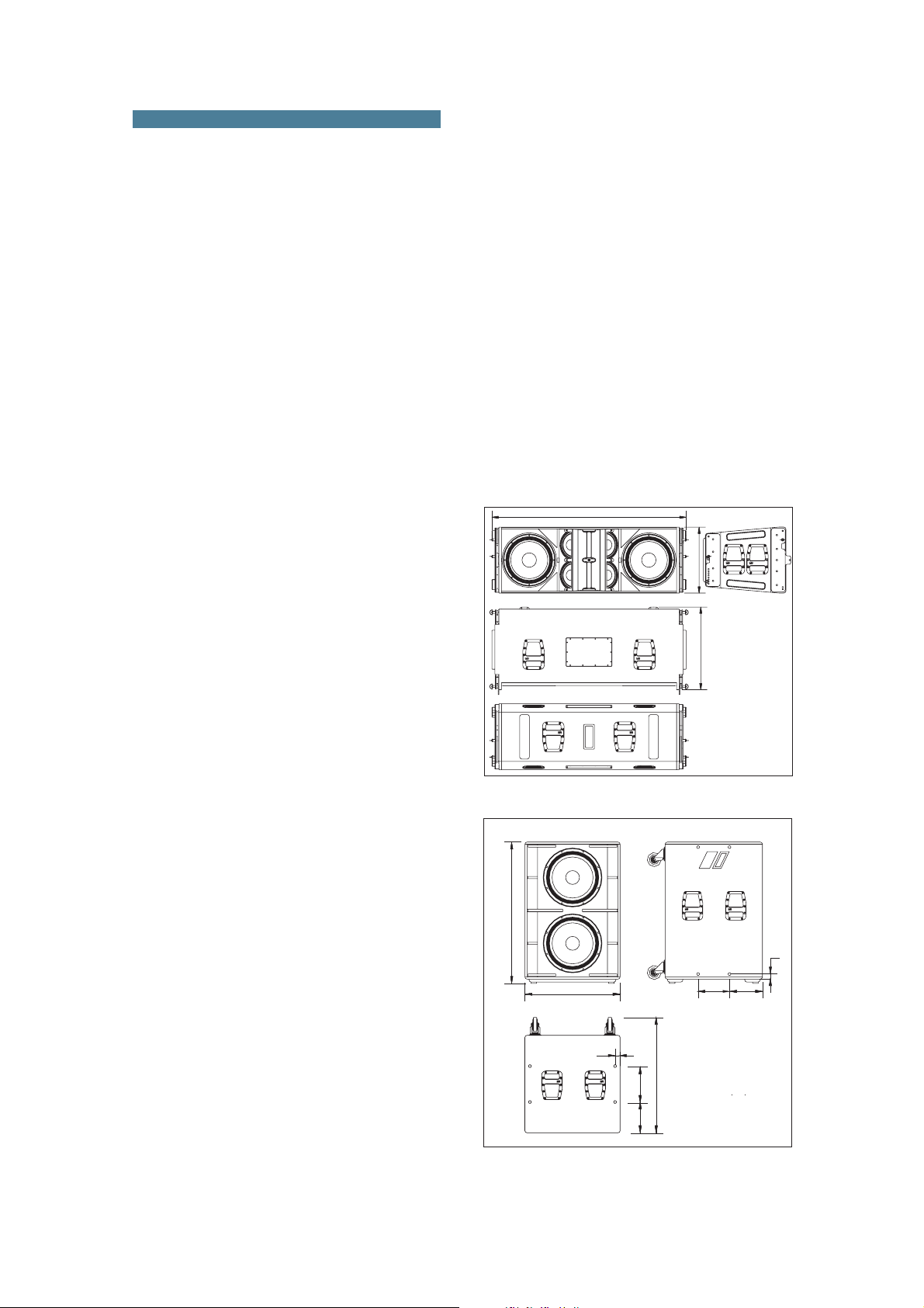
1. SYSTEM DESCRIPTION
The D.A.S. Audio AERO series offers two
units for applications requiring precise control of the
vertical coverage andhigh sound pressure levels.The
AERO-48 is an externally powered, three-way, high
efficiency line arraymodule which integrates two 15”
low frequency units with 4” voice coils, four 8” midrange devices which utilize 2.5” voice coils and two
compression drivers with 3” coils and 1.5” exit
geometry ina singleunit. Thecompression drivers are
coupled to two Serpis high frequency plane wave
adaptors insuring coherent high frequency summing
and the generation of a flat, isophasic wave front.
When increased sound pressure level in the low
frequency range is required, the system can be used
inconjunction withthe AERO-218 subwooferunit.
SUB
The system is ideal for applications such as
large-scale outdoor/indoorevents inarenas, stadiums
or theaters. Use of the DSP-3VS digital processor is
recommended for the AERO-48 and the DS
the subwoofer system. Not usingthe
P-1Sub
for
DSP-3VSdigital
processor with the AERO-48 will adversely affect the
soundquality andmay damagesystem components.
The model AERO-48 includestwo 15GN 15”
cone transducer with 4” EFW voice coils and
Neodymium magnet assemblies in a bass-reflex
configuration.Four 8MN, 8”speakersarranged ona V
shape, incorporating 2.5” EFW voice coils,
Neodymium magnet assemblies and TAF cooling
system are used for mid-range reproduction. High
frequencies are handled by two M-10N high
frequency compression drivers with 3” EFW coil,
Neodymium magnet and 1.5” exit coupled to twin
SERPIS plane wave guide. The SERPIS plane wave
adaptor alsoserves asa heatsink for thecompression
driver.
The AERO-218 includes two 18GN 18”
SUB
cone transducers with 4” EFW voice coils and
Neodymium magnets. This cabinet is intended for
applications when extending the frequency range of
thesystem isrequired.
1400
WARNING!DONOTSUSPENDFROMTHISHANDLE
WARNING!DONOTSUSPENDFROMTHISHANDLE
¡ATENCIÓN!NOCUELGUELACAJADEESTEASA¡ATENCIÓN!NOCUELGUELACAJADEESTEASA
475
¡ATENCIÓN!NOCUELGUELACAJADEESTEASA¡ATENCIÓN!NOCUELGUELACAJADEESTEASA
Both units are manufactured using 15/18
mm Finnish Birch plywood. The AERO-48 enclosure
shape istrapezoidal with5º angles.The AERO-218
SUB
enclosure is rectangular. The Aero-48 system
incorporates captive rigging hardware which is
compatible with one another and designed toprovide
a fast, simple and safe rigging by means of quick
release safetypins. Splayangles canbe changedfrom
0º to 3.2º in 0.8º increments and from 3.2º to 9.6º in
1.6ºincrements.
Tofacilitatetransport, theAERO-48 unitsare
equipped with a PL-48 front dolly panel attached by
means ofthe rigginghardware. The frontdolly panelis
useful when rigging systems. The PL-48S, a metal
dolly for vertically stacking 3 to 4 AERO-48 units is
available as an accessory. The AERO-218 units
SUB
canbe movedby wayof thefour rearlocated casters.
The loudspeakers used in the system
feature advanced technologies; new TAF (
cooling systems,Neodymium magnetic circuits
flow)
total air
which allowfor importantweight reductions, titanium
diaphragms for the high frequency sections,and lowmid frequency cones manufactured using crossed
fibers andelastic suspension thatprovide exceptional
stabilityin thevertical plane.
1010
823
595
AERO-48
ALL DIMENSIONS IN MILIMETERS
WARNING!DONOTSUSPENDFROMTHISHANDLE
WARNING!DONOTSUSPENDFROMTHISHANDLE
¡ATENCIÓN!NOCUELGUELACAJADEESTEASA
¡ATENCIÓN!NOCUELGUELACAJADEESTEASA
224
236
36
WARNING!DONOTSUSPENDFROMTHISHANDLE
¡ATENCIÓN!NOCUELGUELACAJADEESTEASA¡ATENCIÓN!NOCUELGUELACAJADEESTEASA
¡ATENCIÓN!NOCUELGUELACAJADEESTEASA¡ATENCIÓN!NOCUELGUELACAJADEESTEASA
WARNING!DONOTSUSPENDFROMTHISHANDLE
680
36
¡ATENCIÓN!NOCUELGUELACAJADEESTEASA
WARNING!DONOTSUSPENDFROMTHISHANDLE
WARNING!DONOTSUSPENDFROMTHISHANDLE
¡ATENCIÓN!NOCUELGUELACAJADEESTEASA¡ATENCIÓN!NOCUELGUELACAJADEESTEASA
¡ATENCIÓN!NOCUELGUELACAJADEESTEASA¡ATENCIÓN!NOCUELGUELACAJADEESTEASA
WARNING!DONOTSUSPENDFROMTHISHANDLE
¡ATENCIÓN!NOCUELGUELACAJADEESTEASA
WARNING!DONOTSUSPENDFROMTHISHANDLE
256
220
AERO-218SUB
ALL DIMENSIONS IN MILIMETERS
Aero-48 Manual del usuario/ User´s manual 30
Page 4
2. RIGGING SYSTEM
2.1WARNING
Thismanual containsneeded informationfor
flying DAS Audio line array systems, description of
the elements and safety precautions. To perform any
operations related to flying the system, read the
present document first, and act on the warnings and
advice given. The goal is to the allow the user to
become familiar with the mechanical elements
required to fly the acoustic system, as well as the
safety measures to be taken during set-up and
teardown.
Only experienced installers with adequate
knowledge of the equipment and local safety
regulations should fly speaker boxes. It is the user's
responsibility to ensure that the systems to be flown
(including flying accessories) comply with state and
localregulations.
The working load limits in this manual are
the results of tests by independent laboratories. It is
the user's responsibilityto stay within safe limits.It is
the user's responsibility to follow and comply with
safety factors, resistance values, periodical
supervisions and warnings given in this manual.
Product improvement by means of research and
development is ongoing at D.A.S. Specifications are
subjectto changewithout notice.
To this date, there is no international
standard regarding the flying of acoustic systems.
However, it is common practice to apply 5:1 safety
factors for enclosures and static elements. For slings
and elements exposed to material fatigue due to
friction andload variation the followingratios must be
met; 5:1 for steel cable slings, 4:1 for steel chain
slings and 7:1polyester slings. Thus, anelement with
a breaking load limit of 1000 kg may be statically
loaded with 200 kg (5:1 safety factor) and
dynamicallyloaded with142 Kg(7:1 safetyfactor).
When flying a system, the working load
must be lower than the resistance of each individual
flying point in the enclosure, as well as each box.
Hanging hardware should be regularly inspected and
suspect units replacedif in doubt. This isimportant to
avoid injury andabsolutely no risks shouldbe taken in
this respect. It is highly recommended that you
implement an inspection and maintenance program
on flyingelements, including reportsto be filledout by
the personnelthat willcarry out theinspections. Local
regulations may exist that, in case of accident, may
require you to present evidence of inspection reports
andcorrective actionsafter defectswere found.
Absolutely no risks should be taken with
regards to publicsafety. Whenflying enclosures from
ceiling support structures, extreme care should be
taken to assure the load bearing capabilities of the
structures so that the installation is absolutely safe.
Do not fly enclosures from unsafe structures. Consult
a certified professional if needed. All flying
accessories that are not supplied by DAS Audio are
theuser's responsibility.Use atyour ownrisk.
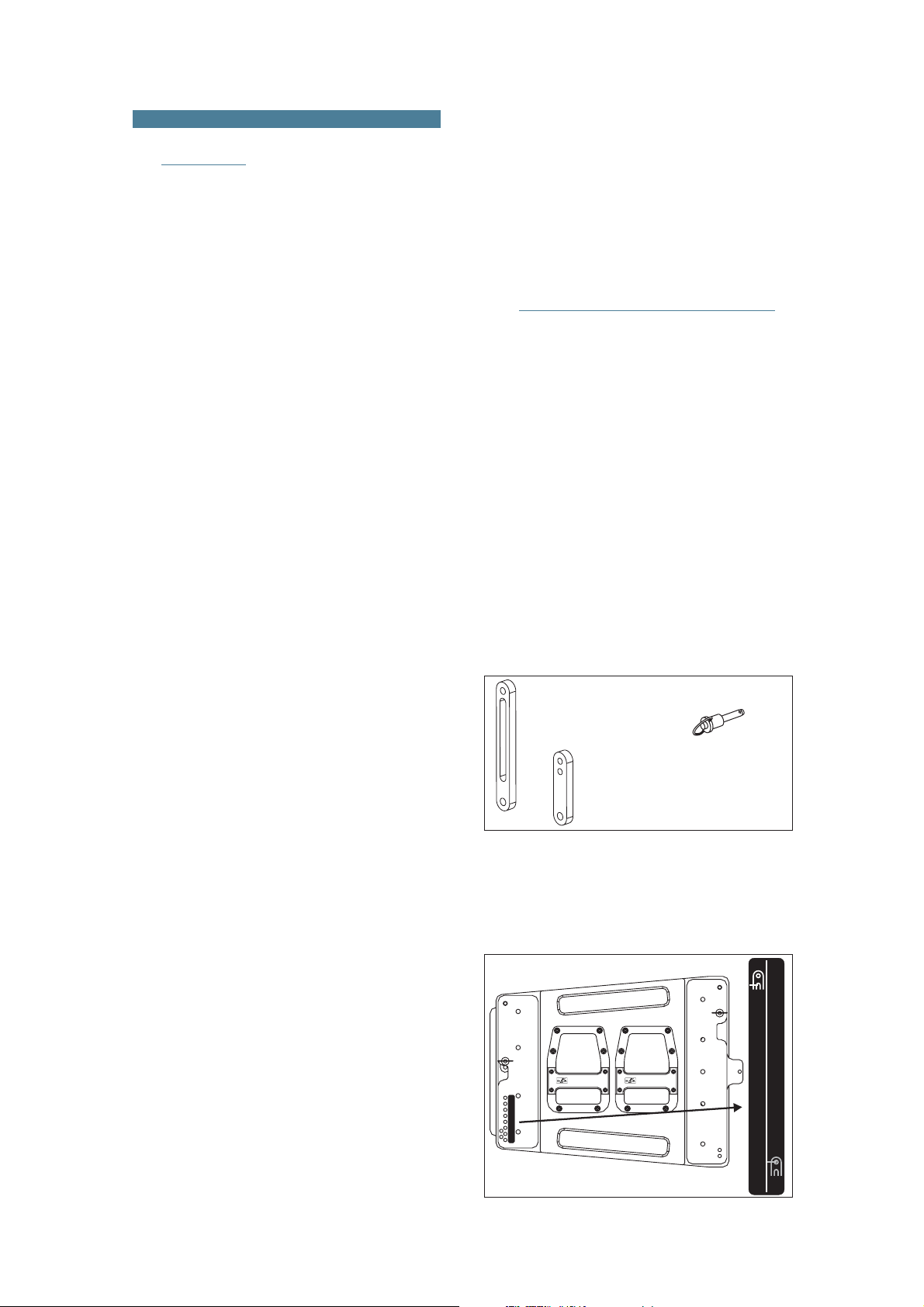
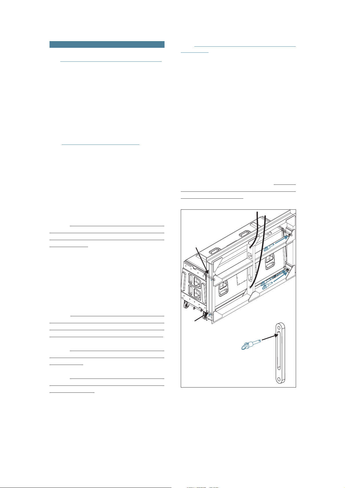
2.2 DESCRIPTION/ACCESSORIES
DAS Audio AERO-48 line array systems,
include 2 rigging structures on each side of the box.
Manufactured from zincplated steel they are painted
black and are affixed to aninternal plate with special
crop resistant screws. Two special stainless steel
guides are assembled to each of the structures:
G1A48(front guide)and G2A48(back guide),allow for
stacking or flying of boxes.
Splay angles can be
changed from 0º to 3.2º in 0.8º increments and from
3.2º to 9.6º in 1.6º increments.
To lock both guides,
six (6) quick release safety pins (supplied) must be
used.
The G1A48 front guide provides a solid
connection to the box and whatever is on top of it,
while the G2A48 rear guide determines the vertical
splay angle (whether stacked or flown), as a function
ofthe holewhere thepin getsinserted.
G2A48
QUICK RELEASE PIN 8X30
(6 UNITS PER CABINET)
G1A48
To aid the setting of the G2A48 guide in the
corresponding holein the topbox, eachhole is labeled
with an associated angle, both for stacked and flown
applications. To fit the guides into the holes, highly
resistant 8 mm quick release pins with a ball safety
lock areused.
Fly
9.6º
8º9.6º
6.4º8º
4.8º6.4º
SOUNDPRODUCTS
WARNING!DONOT SUSPENDFROM THISHANDLE
®
¡ATENCIÓN!NOCUELGUE LACAJADE ESTEASA
SOUNDPRODUCTS
WARNING!DONOT SUSPENDFROM THISHANDLE
®
¡ATENCIÓN!NOCUELGUE LACAJADE ESTEASA
4.8º
3.2º
2.4º
1.6º
0.8º
3.2º
1.6º
0.8º
0º
0º
Stack
Aero-48 Manual del usuario/ User´s manual 31
Page 5

For flying boxes and defining the splay
angle, the pins must beinserted in the slot of guide 2,
G2A48, whereas for stacking ( ), the pin goes
throughthe tophole ofthe guide.
stacked
C) PlatformPL-48
The PL-48dolly panels facilitate transport of
the AERO-48 systems. They can also be used to
facilitate flyingthe systems.Each cover isattached to
the enclosure by using the flying hardware attached
to each box and is fixed with the quick release safety
pins.
STACK
All ofthe elements neededto rigor stack the
systems are integralto the enclosure (
and the quick release safety pins). The additional
items needed are the AX-AERO48 flying grid(bumper
bar), chains and hoists, the PL-48 or PL-48S dolly
platformsand theAX-COMBOflying grid.
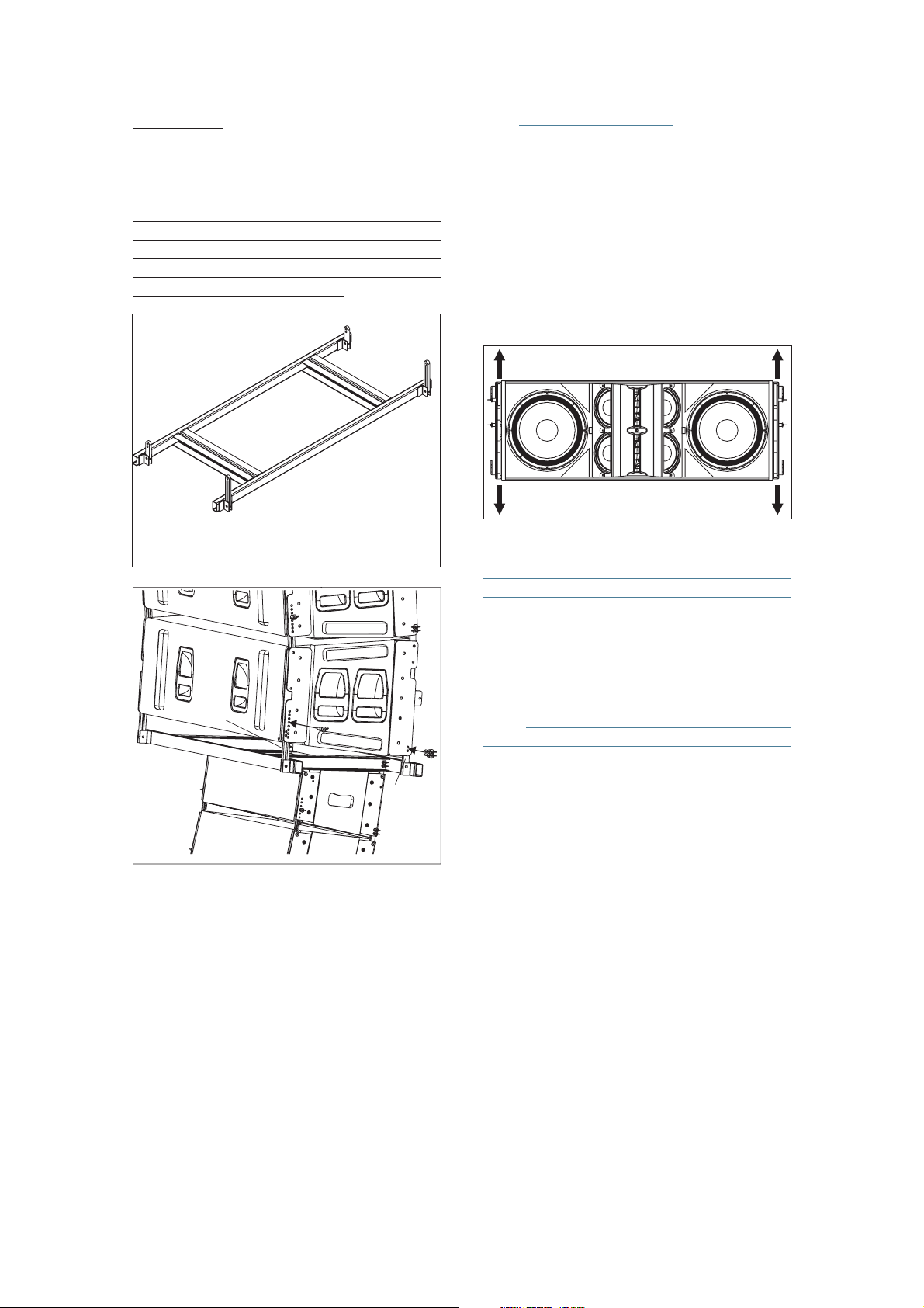
A) AX-AERO48
The AX-AERO48 grid is made from 100 x50
x 6mm steel tubing and is designed to handle great
loads. It features a center reinforcement bar that is
also used for the lifting slings. The force of both the
rear and the front chain hoist will determine the tilt
angle of the whole array. The structure will be
attachedto thefirst enclosureof thearray bymeans of
the guides G1A48, G2A48, and six quick release
safetypins.
FLY
G1A48, G2A48
Pickup points
PL-48
D) PL-48S
The PL-48S platformis a valuableaccessory
which allows up to 3 or 4 AERO-48 units to be
transported in a stacked position, ready to be flown.
The PL-48S is made from steel and has 4 heavy duty
casterswith lockingbrakes.
PL-48S
Weight
: 75Kg (165 lbs)
Dimensions: 144x93x10 cm
(HxWxD)
B) Chainhoists
AX-AERO48 flyinggrid (bumper bar), whichshould be
used with two hoists, one located inthe front and the
other inthe rear.The hoists shouldhave a minimumof
1 Ton loadcapacity when flying up 8units and a 2 Ton
loadcapacity whenflying 9to 16units.
1 8cabinets-->
9 16cabinets-->
Aero-48 Manual del usuario/ User´s manual 32
57x36.6x4 in
All units in a column will be flown from the
Chain hoist load capacity
>1000Kg
>2000Kg
Page 6
D) AX-COMBO
2.3 SAFETY FACTORS
The AX-COMBO is a rigging adapter to be
used when Aero-28 units are needed to be flown
under AERO-48 units asdowfill systems. Maximum 6
CA-28A unitsand 8 CA-28/CA-28B unitscan be flown
from this rigging grid. The AX-COMBO includes front
and rear steel guides which permit variation of the
angle between it and the last AERO-48 cabinet in the
cluster.Anglesvary from1.8º to9.6º.
G1A48
G2A48
G2A48
Weight
: 16.5Kg (36.3 lbs)
Dimensions: 143x60x5cm (56.3x23.6x2in)
AERO-48
The safety factor is defined as the
coefficient between the
breaking load limit and the
maximum safe working load limit (SWLL). In this
case, the breaking load limit of each of the flying
points is 4,000 kg (8,820 lbs) as determined by
destructive testing in independent laboratories. With
a 10:1 safetyfactor, atotal amount of 1,600kg (3,527
lbs) can be flown from the 4 flying points. Each flying
point has a capacity of 400 kg (882 lbs) with a 10:1
safetyfactor.
4 x 400Kg (10:1)
T
he maximum number of units that can be
suspended from the AX-AERO48 flyinggrid is 16. The
maximum limits established by the manufacturer
shouldnever beexceeded.
G2A48
AX-COMBO
CA-28
G1A48
The AX-COMBO is joined to the last AERO48 cabinet using G1A48 and G2A48 included steel
guides and6 quickrelease pins.The angle dependson
the hole of the rigging structures where the pins are
inserted, through the slots of G2A48. The first AERO28 unit is joined to the AX-COMBO using its G1A and
G2Aincluded camlinks.
Theuseoftwohoistswitha loadcapacity as
expressed on the previous page is mandatory. It
should be kept in mind that at certain moments, the
complete load may be supported by only one of the
hoists.
This is why the load capacity of the individual
hoist must be superior to the weight of the array
column.
Aero-48 Manual del usuario/ User´s manual 33
Page 7
3. ASSEMBLING AN ARRAY
3.1TRANSPORTING THE CABINETS
AERO-48 units can be transported by using
the frontpanel dollyPL-48 orby usingthe PL-48Ssteel
dolly which can transport a maximum of 3 AERO-48
stackedin anarc or4 unitsstacked vertically.
The Aero-218SUBcan be transportedon the
rear located casters. Their rectangular shape
facilitates stacking without the use of the rigging
hardware.
3.2 PLANNING/INSPECTION
3.3 ASSEMBLING AN ARRAY “ONE
BY ONE”
When few units are to be used (minimum
systems recommended is 6 units) or when the dolly
platforms cannot be used due to a lack of space, the
enclosures willhave tobe hung “oneby one”.The first
step will to attach the AX-AERO48 grid structure to
the hoists.The chain slings needto be attached tothe
structure using the shackles provided with the grid.
Once this has been accomplished, the grid structure
can be placed in a vertical position by lifting the rear
hoist and lowering the front hoist so that the rear of
the grid is on top and the front of the grid at the
bottom,ready toreceive thefirst box.
Before installing the AERO systems it is a
good idea to run a simulation with the AEROWARE
program utilizing the venue dimensions. This way we
can determine the needs that should be met by the
rigging structures such as hoists, cranes, beams,
rigging points, etc. Besides providing weight
information, the program also provides users with
splay angle information, safety pin positions and
coveragepredictions.
It isextremely important toassure that each
and every one of the aforementioned structures is
capable of supporting a superior load than that of the
completesystem.
Inspection is the next step after planning
and acquiring all the necessary parts needed to
elevate thesystems. All parts,including the hardware
attached tothe enclosure,the safetypins, etc. should
be thoroughly inspected before each use. Units
exhibiting deformations, cracks or any other defect
shouldbe replacedwith newunits.
It is important to establish an inspection
routine for the complete rigging system before each
event or installation as well as establishing the
maximumload specificationsof thehoists tobe used.
The next stepis to attach thefirstunit to the
grid by introducing the G1A48 and G2A48 guides in
the receiving points ofthe grid structure and assuring
them with the six safety pins. The safety pins should
be inserted in the slot of the G2A48. It is very
important to make sure that the pins have been
insertedand lockedcorrectly.
AERO-48
G2A48
4
5
6
G1A48
3
2
1
AX-AERO48
Rigging should be carried out by experts
familiar with the way the systems function and their
characteristics.
On occasions, it may be convenient to have
additional tie down points to impede the array from
twistingor swinging.
Aero-48 Manual del usuario/ User´s manual 34
The quick release pins(3 and 4) must be
inserted through the slot of G2A48
Once the first unit of the array has been
attached to the AX-AERO48, the assembly should be
lifted by way of the rear hoist until the wheels of the
PL-48dolly platform lift off theground. From thispoint
on, the front hoist can be used to lift the box into a
horizontalposition.
3+4
Page 8
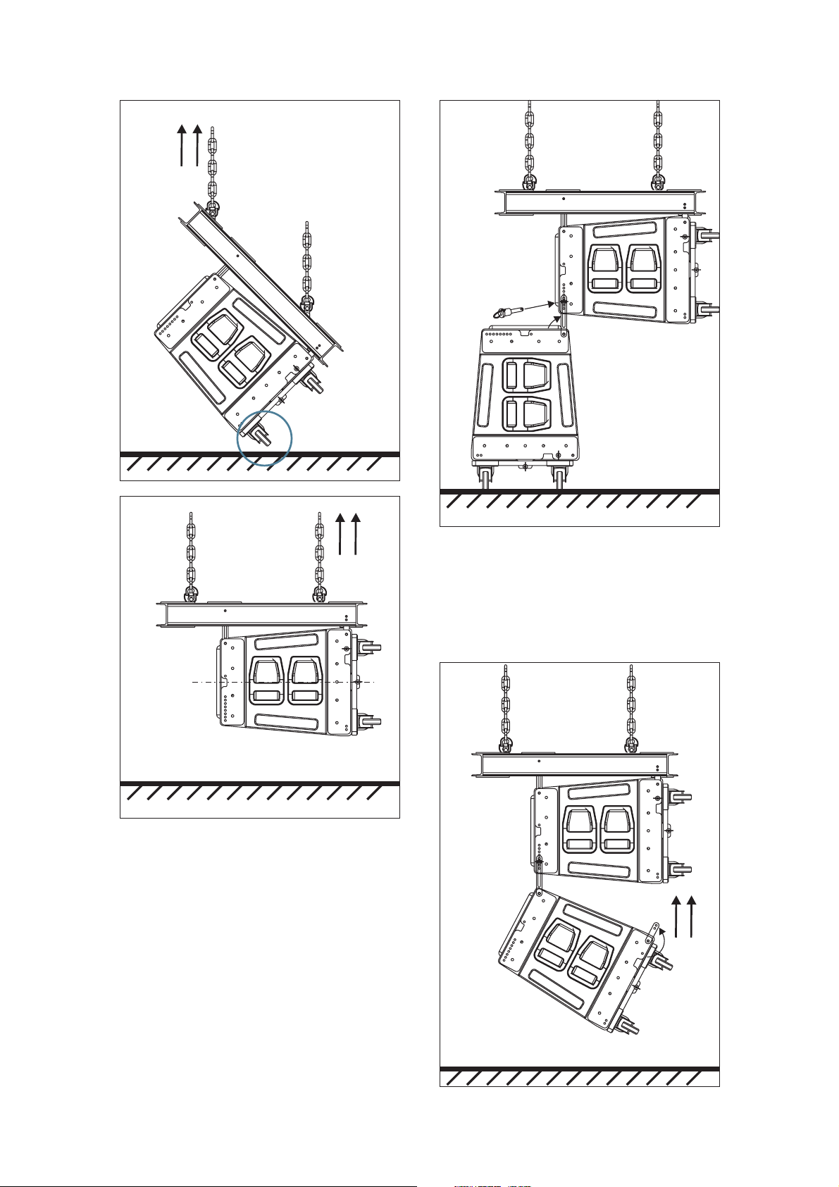
Lifted by way of the rear hoist
until the wheels of the PL-48
dolly platform are off the ground.
Lift with the front hoist
until the box is in a
horizontal position.
Swing the G2A48 guide
into place and secure it
with the safety pin.
Once the splay angle between the first two
boxes has been determined, the front of the box can
be lifted into place. Three people will be needed to
undertake thisoperation, two tolift the boxand one to
fitthe G1A48guide andsafety pinsinto theupper box.
0º
Once the firstbox has been placed at0º and
raised approximately 75cm (30 in) the second box of
the array can be placed nearby. Once located in
position, the G2A48 guides of the second box should
be freed and inserted in the rear located receiving
points of the suspended box and secured with the
safetypins.
Lift the box and free
the G1A48 guides.
35Aero-48 Manual del usuario/ User´s manual
Page 9
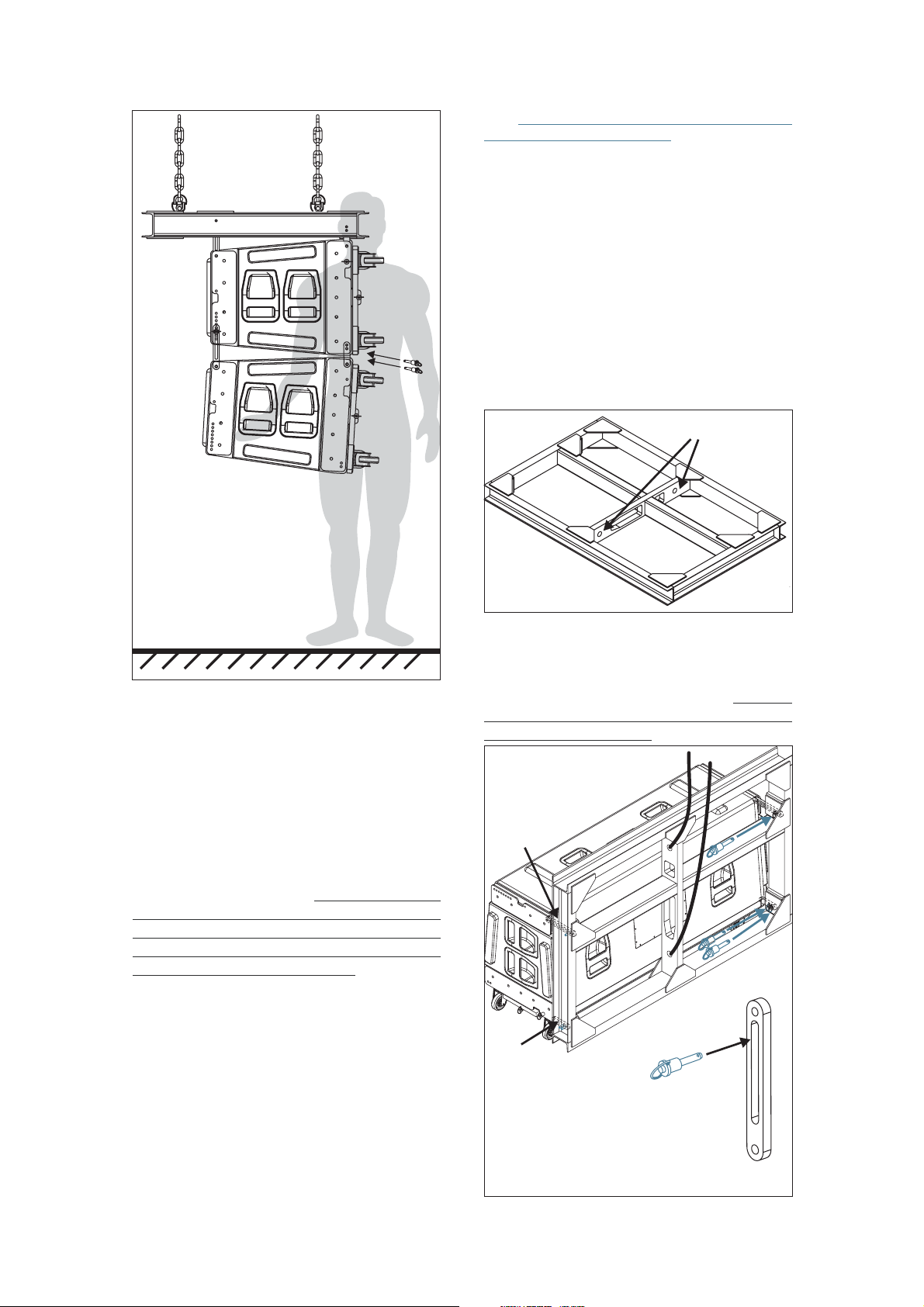
Lift the box and introduce the
G1A48 guides securing them
with the safety pins.
Once the boxes have been joined, the front
dolly panels can be removed. The next boxes should
be attached “one by one” using the methods
described. Finally, the array should be hoisted to the
correct height and secured with slings to avoid
swinging.
3.4 ASSEMBLING AN ARRAY USING
THE PL-48 PLATFORM
The PL-48 platform can be used to easily
transport AERO-48 units to the assembling area. To
use this method ofassembling and hoisting the array,
there must be enough space to permit linking all the
boxesfrom thefront ofthe therigging hardware.
The first step will be to attach the AXAERO48 grid and the 2 hoists. Once this has been
accomplished, the grid structure can be placed in a
vertical position by lifting the rear hoist and lowering
the front hoistso that the rear of thegrid is on top and
the frontof the gridat the bottom,ready to receivethe
firstbox.
Rigging points
The nextstep is to attachthe first unit tothe
grid by introducing the G1A48 and G2A48 guides in
the receiving points ofthe grid structure and assuring
them with the (6) safety pins. The safety pins should
be inserted in the slot of the G2A48. It is very
important to make sure that the pins have been
insertedand lockedcorrectly.
AERO-48
This method is more time consuming than
assembling an array by the “all at once” procedure,
but is appropriate forsituations due to a lack of space
in which to array the system. During the process, the
safety pins should be checked making sure they are
secured correctly. Once the complete array has been
lifted into place, additional slings should be attached
tosecure thearray andavoid swinging.
G2A48
G1A48
3
2
4
1
5
AX-AERO48
6
3+4
36Aero-48 Manual del usuario/ User´s manual
Page 10
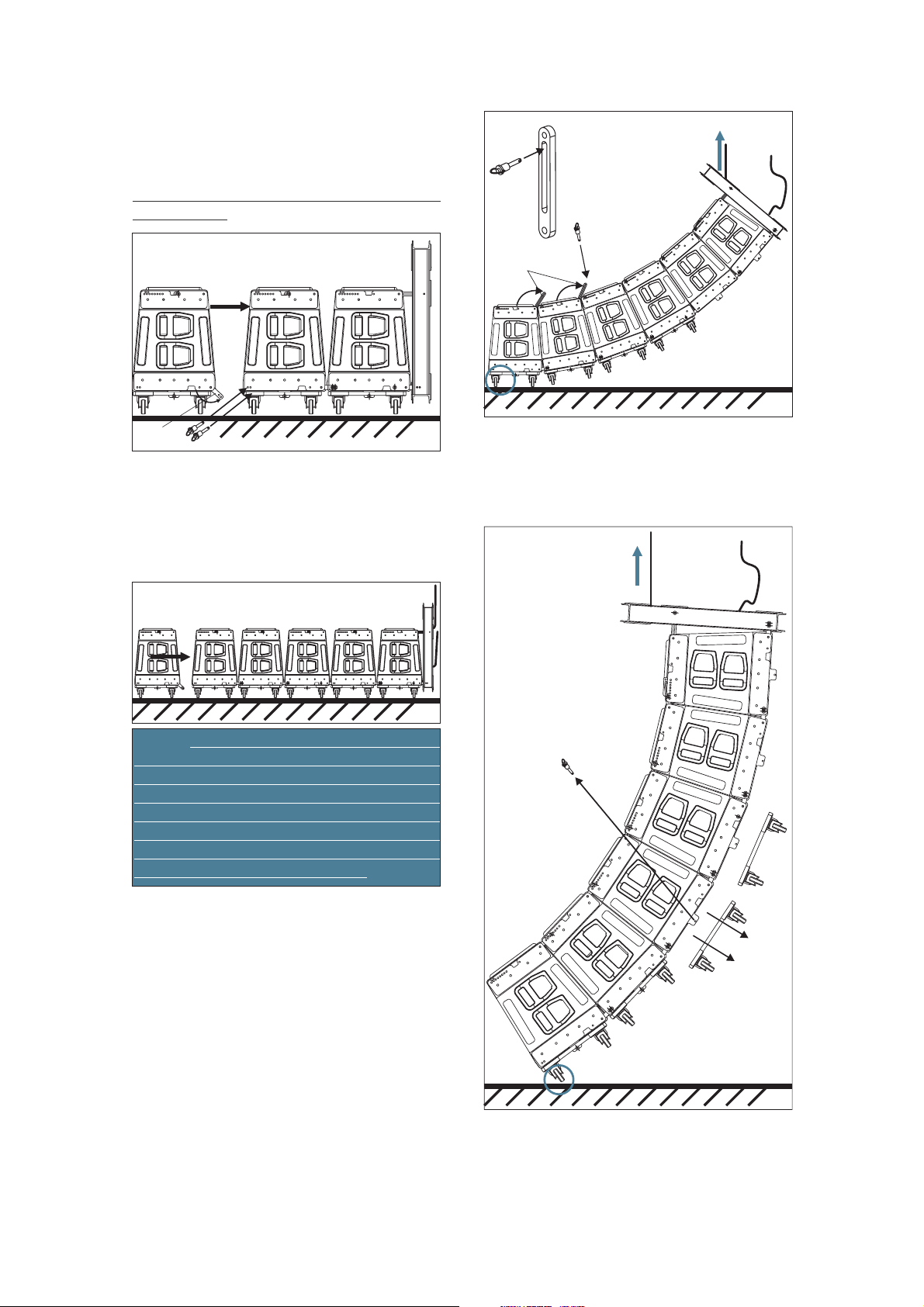
Once the first box is attached to the
structure, the remaining boxes should be brought to
the arrayand attachedrepeating theprevious steps (1
and 2) using G1A48 guides and safety pins per side
making sure that the pins have been inserted and
lockedcorrectly.
1
G2A48
Rear hoist FIRST!!
3
5
4
4
G1A48
same manner until all the array units are attached to
one another. For example, if we are assembling a six
unit array, the process will be repeated six times.
When all theunits are attached, the complete arrayis
readyto behoisted.
lifted from the rear hoist (3) so that the rear of the
enclosures come together due to their trapezoidal
shape. The front motor will be used only to take up
slack in thechain, all the weightshould be on therear
hoist. Proceed in this manner until the wheels of the
last enclosure are off the ground. From here on, the
arraycan nowbe liftedwith bothmotors.
2
Proceed to attach theremaining units in the
The complete assembly should begin being
The front motor will be used only to take up
slack in the chain,all the weight should be onthe rear
hoist. When the wheels of the last enclosure are off
theground thearray canbe liftedwith bothmotors.
Rear hoist FIRST!!
6
When the rear of the enclosures come
together,the G2A48 rear guides should be positioned
(4) into the hardware of the box above, inserting (5)
the safety pinsin the correct angleposition. Since the
boxesare flown,the safetypins shouldbe inthe slotof
theG2A48 guide.
As the array assembly is lifted (6 & 7), the
PL-48platforms shouldbe removed.
7
Once thecomplete array has beenlifted into
place, additional slings should be attached to secure
thearray andavoid swinging.
37Aero-48 Manual del usuario/ User´s manual
Page 11

Aero-48 Manual del usuario/ User´s manual 38
Page 12

To lower the system, both hoists should be
used until the lowest box is about 1 meter from the
ground. From there on, only the front hoist should be
used so that the array assembly begins to lean
forward, atthe same time, thePL-48 platformsshould
be reattached. When the wheels of the lowest
enclosure are firmly on the ground, the array
assemblycan nowbe loweredusing therear hoist.
While the array assembly descends, the
rear of the enclosures will come together, at that
moment, the safety pins which hold the G2A48
guides in place should be removed. Once removed,
the guides should be swung back into the box they
belong to. Finally, the boxes should be totally
detached from one another by releasing the G1A48
guide.
3.5 ASSEMBLING AN ARRAY
USING THE PLATFORM PL-48S
The PL-48S platform can be used to easily
transport 3/4 units of the AERO-48; in both arc shape
orstacked onthe platform.
The PL-48S platform can be used to
transport boxes forming a vertical arc, ready to be
flownor simplystacked.
Either way, dueto theweight of theboxes, it
isrecommendedthat forthe firsttime, the enclosures
be placed on the platform from a flown position. In
other words, the array should be suspended (either
onebyone orusing thePL-48S)and thenlowered onto
thePL-48S ingroups.
A) Cabinets splayed in arc (MAX. 3 units):
If we want to place six AERO-48 units on 2
PL-48S, the first step would be to suspend them all,
and then lowerthe array assembly onto the platforms
ingroups ofthree.
Last cabinet of the array
MAX. 3
units
Splayed units on PL48S ready to be rigged.
The PL-48S platform has two types of
moving pieces. One of them is fixed (PL-48S_2) and
can only be swung around, the other is free (PL48S_1) andis joinedto theplatform bywayof asafety
pin. The smaller piece PL-48S_1 attaches to the front
enclosure hardwareand the largerPL-48S_1 attaches
tothe back:
MAX. 4
units
Units stacked on a PL48S.
PL-48S_1
Lower thearray untilthe lowest boxis about
15cm (aprox.6 in.)above thePL-48S platform.
2
1
Release the PL-48S_2 piece by removing
the safety pins (1). Next, swing the pieces and
introduce them (2) into the rear rigging hardware of
thelowest box,securing themwith thesafety pin(3).
PL-48S_2
Aero-48 Manual del usuario/ User´s manual
39
Page 13

Once thetwo PL-48S_2 havebeen attached
to theboxes (3) usingone safety pinper piece, thePL48S_1 pieces can be attached. Remove the safety
pins (4)and insert them into the rigging hardware (5)
securing them(6) byusing twopins perpiece.
3
1
5
4
6
Once the PL-48S_1 and PL-48S_2 have
been securedto the lowerbox, this shouldbe lowered
so that the PL-48S_1 piece can be secured to the PL48Splatform (7)using thesafety pins.
7
The lowest box is now attached to the
platform. Now the array should be lowered until the
boxes are resting on one another. When the lower
three boxes are in this position, the safety pins
attached to the G2A48 guides joining boxes 3 and 4
should be removed to separate the array into two
groupsof boxes.
2
3
8
9
4
9
8
9
5
8
6
On flown systems, boxes are numbered
from top to bottom, the top box being number 1 and
thelower boxbeing numbersix.
With the number 4, 5 & 6 boxes resting on
each other, the safety pins that definethesplay angle
can be removed (8) and the PL-48S_2 guides can
return to their stored position (9). It is mandatory to
remove the safety pins between boxes 3-4, but
between 4-5, and 5-6, they can be left in place with
theangle preparedfor thenext event.
40Aero-48 Manual del usuario/ User´s manual
Page 14

Boxes 3-4 should be separated at the front
by removing the safety pins (10) that secure the
G1A48guides.
The first groupof boxes has now been freed
and isstacked safely onthe PL-48S platform.Tomove
the stack, slightly raise the upper group of boxes and
rollaway thelower group.
10
12
11
When the G1A48 pieces have been freed,
they should be turned (11) and stored (12) within the
corresponding box, in this case number 4, using the
mechanismincluded inthe rigginghardware.
41Aero-48 Manual del usuario/ User´s manual
Page 15

The next step is to roll under the remaining
boxes, an empty PL-48S and lower the boxes until
they are within close proximity of the platform. The
procedure should now be repeated, freeing the PL48S_2 pieces (13) from the platform, turning them
(14) and securing them (15) to the rear rigging
hardwareof thenumber 3box.
The last step consists of lowering the
remaining arrayso thatthe safetypins canbe inserted
(18) into the holes of the PL-48S_1 pieces and the
platform.
15
PL-48S_2
14
Continue lowering the systems and secure
(16) the PL-48S_1 pieces tothe front rigging points of
box3, inserting2 safetypins ineach (17).
Whenever a safety pin is inserted, it is
recommended thatthey be checked tomake sure that
they are correctly attached. Pull the safety pin
outward to make sure that it is in the locked position.
17
13
16
PL-48S_1
18
As inthe caseof thefirst groupof boxes,itis
not necessary to remove the safety pins securing the
G2A48 guideswhich determine splayangle. They can
remain in as they are, ready for the next event. The
samegoes forthe AX-AERO48grid.
B) Stacked units (MAX. 4 units):
Besides using the PL-48S platform for
transporting and flying the systems, it can also be
used for ground stacking.
boxes, it is recommended thattheybe flown first and
then lowered to the platform and stacked. For
stability reasons, it is recommended that no more
than 4boxes be stacked.
used, theyshould bearranged sothat thesplay angles
do not make the platform unstable. Once the boxes
are flown, they can be lowered onto the PL-48S
platform by using the hoists to position the array so
that the
guides.
safety pins can be inserted into the G2A48
Due to the weight of the
In theevent that 4 boxesare
The PL-48S_2 piece on the platform has 2
holes, the lower one offers a 0º angle between box
and platform and the upper hole offers a 1.6º angle,
meaningthat thebox isleaning forward.
42Aero-48 Manual del usuario/ User´s manual
Page 16

The arrangement in the following picture is
an unstable one.The smaller the splay anglebetween
cabinets, the more the stability. Obviously, the most
reliable stack in terms of stability istheone when the
splayangle betweenall ofthe cabinetsis 0º.
6.4º
4.8º
-1.6º
The anglebetween the box andthe platform
will be -1.6º whenthe safetypin isinserted inthe hole
on thebottom of theback guide, andthe holeon top of
the PL-48S_2 piece. Let us go now through the
complete process of stacking the boxes after they
havebeen previouslyflown.
3.2º
As mentioned above, the hole in which the
safety pin is inserted in the PL-48S piece will
determinethe splayangle ofthe bottombox, beit 0ºor
-1.6º. The following pictures will make things more
clear.
0º
The anglebetween the box andthe platform
will be 0º when the safety pin is inserted in the hole
on the bottom of the back guide, and the hole on the
bottomof thePL-48S_2 piece.
1
2
43Aero-48 Manual del usuario/ User´s manual
Page 17

After having rolled a PL-48S platform under
the array, the PL-48S_1 pieces (1,2 and 3) must be
detached from the platform and introduced (4) in the
frontrigging structureof thelower box.
Now the entire cluster can be lowered so
thePL-48S_1 piecesget intoreach ofthe platform.
Thenext stepis tofix thePL-48S_2 piecesto
the rear rigginghardware of the box.In order to doso,
the platform shouldbe raised up till thebottom hole in
the rigging hardware and the hole in the PL-48S_2
match together. Then the safety pins can be inserted
in the holes. As has been said before, the splay angle
between the platformand the box is given bythe hole
usedin thePL-48S_2 piece.
4
3
Both PL-48S_1 pieces must now be
attached (5)to thebox onthe bottom bymeans oftwo
safetypins oneach side.
5 PL-48S_1
7
6
PL-48S_2
The hole chosen in this example, is the one
onthe bottomof thePL-48S piece,being 0ºthe angle.
44Aero-48 Manual del usuario/ User´s manual
Page 18

At thispoint thePL-48S_1and thePL-48S_2
piecesarebothconnectedto thebox. Thereis onlythe
PL-48S_1 piece left to be attached to the platform.
Move the platform upwards till the holes in the PL48S_1 piece and the holes in the platform match
together.Theninsert thesafety pins(8).
Lower the cluster till the platform is resting
onthe floor.
9
8
When the boxes are flown the safety pins
must be insertedin the G2A48 slots.Now we want to
stack theboxes, so thenext step isto release thepins
from theslots and introducethem in the G2A48holes.
It must be done by first lowering the boxes till the
safety pins can be removed, then raise the boxes till
the holes fit together and finally insert the safety pins
again.
Fly
G2A48
Stack
G2A48
10
11
G2A48
1
2
3
12
4
45Aero-48 Manual del usuario/ User´s manual
Page 19

The cluster must now be lowered (10) until
the safety pins (11) on the rear side of box number 4
can beremoved. Once safetypins have been released
the cluster must be raised or lowered (13) until the
hole in the G2A48 piece matches with the hole that
determinesthe anglechosen bythe user.
13
4.8º
14
15
16
17
Safety pinscan now be inserted(14). In this
example, the set up angle between boxes 3 and 4 is
4.8º.
It is important to check that pins cannot be
removed by pulling outward and that they have been
inserted in the G2A48 hole instead of the guide slot.
Otherwise the box would not remain in the expected
angle.
The procedure is the same for the next
boxes. The cluster must be lowered again (15) until
the safety pins of box 3 are loose. Remove the pins
(16) so the G2A48 rear guides return to their stored
position (17). Insertthe safety pins into theholes (18)
that determine the angle previously selected for
stacking. Repeat the same procedure with box
number 1: lower the cluster (19), free the rear guides
G2A48(20 &21) andselect theangle.
19
20
21
18
3.2º
4.8º
46Aero-48 Manual del usuario/ User´s manual
Page 20

In orderto set upthe angle betweenboxes 1
and 2you must pull up(23) from the griduntil the hole
in the G2A48 piece fits with the hole that determines
thestacking angle.Then insertthe safetypins (24).
23
24
1.6º
3.2º
4.8º
At this point the boxes are safely stacked.
Finally, theAX-AERO48grid should be detached from
boxnumber 1.
47Aero-48 Manual del usuario/ User´s manual
Page 21

3.6 ASSEMBLING A CLUSTER
USING THE PL-48S PLATFORM
AERO-48 boxes canbe easily transported in
groups ofthree when stackedon the PL-48Splatform.
This arrangement is also useful and saves time when
setting up a cluster. Let us see what would the
procedurebe whenflying asix boxcluster.
In order to attach the box on top to the grid,
front guides G1A48 and rear guides G2A48 must be
swung (2) and inserted into the AX-AERO48 grid
receiving points. Oncethis has been done, detach the
6 safety pins from their receptacles and secure the
boxto thegrid.
After the AX-AERO48 grid has been
attached to the motors, it should be lifted at about
1.8m (5.5 ft) from the ground. Now the platform
containing the first threestacked AERO-48 boxes can
berolled underthe grid.
1
2
1
2
Once G1A48,G2A48 of thetop cabinet have
been secured (3) to the grid, rotate
( ), fit them into the upper box rigging hardware and
4
securethem withthe safetypins ( )
Whenever a safety pin is inserted, it is
always advisable to make sure it has been correctly
lockedby pullingoutward.
the G2A48 pieces
5 .See nextpage.
48Aero-48 Manual del usuario/ User´s manual
Page 22

The angles that can be seen in the example
3
3
4
4
are 0.8ºbetweenthe first and secondboxes, and 1.6º
between the second and the third boxes. The cluster
can now be lifted by the two motors, and the PL-48S
platformdetached.
The first step to detach the PL-48Splatform
from the bottom box is to release (6) the safety pins
which secure the PL-48S_1 piece to the platform and
the PL-48S_2 piece to the box. After raising the
cluster a bit, the safety pins which connect the PL48S_1 piece to the box can be released (8) also. PL48S_1 piece should now be reattached again to the
platform.
Select the angle between cabinets
introducing (5) the pins in the holes of the rigging
systemthrough theslot ofG2A48.
0.8º
5
1.6º
5
6
PL-48S_2
8
PL-48S_1
7
6
49Aero-48 Manual del usuario/ User´s manual
Page 23

Place the remaining group of boxes under
thecluster,then lowerthe clusteruntil bothfront sides
get in close proximity. G1A48 front guides (9) of the
first box onthe platform can nowbe swung and left in
the uprightposition, ready to beinserted into thefront
rigginghardware ofthe nextbox.
Lower the cluster until the G1A48 front
guides fit into the rigging hardware ofthe bottom box
andinsert thetwo safetypins (10)perside.
9
10
50Aero-48 Manual del usuario/ User´s manual
Page 24

With the front guides correctly secured,
swing the G2A48 (11) rear guides belonging to the
box on top of the second group and lower the grid till
the guides fit into the rigging hardware of the next
box. Set the angle between both boxes by inserting
thesafety pinsin thecorrect hole.
From here on, the process is similar to the
previously described. Detach the safety pins from
their receptacleson thesides of theboxes, swing(12)
the G2A48 rear guides, place them into the rigging
hardware of the next box and insert (13) the safety
pins in the holes which define the angle previously
selected.
0.8º
11
1.6º
1.6º
13
12
3.2º
13
12
4.8º
13
12
51Aero-48 Manual del usuario/ User´s manual
Page 25

4. SIGNAL PROCESSING
4.2 LIMITER SETTINGS
The use of the DSP-3VS digital processor is
highly recommended when running the AERO-48
sound system, and the use of the DSP-1Sub when
running the AERO-218Sub. Whenever another
loudspeakermanagementsystem isgoing to beused,
it should be configured with the parameters provided
by the manufacturer. Not doing so may damage the
system´s speaker components and affect the sound
quality.
The DSP-3VS digital processor is a threeway crossover with gain controls that offer +/- 6dB
variation per way. The processor has two inputs and
six outputs with level indication and muting for each
of the outputs. The digital processor includes fourth
order filters and parametric equalizers. The user
adjustablelimiters areaccessible fromthe frontpanel.
The DSP-3VS includes 10 presets that can
be selected fromthe front panel. Eachpreset memory
recalls specific operating parameters for a specific
DASspeaker systems.The selectedprogram isvisible
onthe LCDscreen locatedon thefront panel.
4.1 DSP-3VS INSTRUCTIONS
The following formulas can be used to establish the
limiter voltage:
AmplifierData:
rms rms
V=P *Z
G=
rms
V/S
G =20log(V /S)
dB rms
Where P is the amplifier RMS power in
rms
watts
Zis theload impedancein ohms
Gis theamplifier gain
Sis theamplifier sensitivityin volts
dB
G isthe amplifiergain indB
Limitersettings:
dd
V= P *Z
Limitlevel (v)=V /G
d
Limitlevel (dBu)=20log[limitlevel (v)/0.775]
Where P is the maximum power to be
d
deliveredin watts
To selecta program, turn therotary mini-DIP
switch onthe frontpanel labelled“Presets”. Thename
of the recalled preset will appear on the LCD screen.
The firsttime theDSP-3VSis connected, thenumber 1
program for the AERO-48 system will appear on the
frontpanel screen.
To select the limit levels for each of the
ways, turn the rotary mini-DIP switches on the front
panel labelled “Limiters”. The limit level expressed in
Vrmsand dBuappears onthe frontpanel screen.
The “Settings” button allows the user to
check thesaved limitlevels. The limitlevels appear on
the screen and after 5 seconds, the preset program
returnsto thescreen.
Thelimitlevelstobe enteredshould beequal
to or lower than the sensitivity of the amplifiersused.
Amplifier manuals provide the sensitivity at 8 Ohms
and 4Ohms. Takeinto account the load impedanceat
which the amplifiers will be working when adjusting
thelimit levels.
When usingamplifiers with a greateroutput
power than that recommended by the speaker
manufacturer, the limit levels should be adjusted so
notto exceedthe powercapabilities ofthe speakers.
Ejemplo:
Amplifier
Prms
GdB
G
S
1400W@4ohm
1.84 volts@4ohm
850W@8ohm
32dB
40 X
2 volts@8ohm
In this example we are going to feed the
highs of anAERO-48 with one amplifier channel. Total
impedance of 4 M-10N high frequency drivers, as
wired in the AERO48, is 8 Ohms. The maximum rms
power to be delivered to the highs, or Pd, should be
700W(700/4=175W perdriver).
d
P =700W@8ohm
d
V = 700*8=74.8v
Limit level (v)=V /G=74.8/40=1.84
d
Limit level (dBu)=20log(1.84/0.775)=7.6
Important Notice: The programs stored in
the memories of the DSP-3VS have been designed to
provide optimum performance and balance between
the different ways. In order to maintain this balance,
equalgain amplifiersshould beused.
52Aero-48 Manual del usuario/ User´s manual
Page 26

aero-48
5. SYSTEM CONNECTION
CONFIGURATION 1 (3 WAY STEREO SYSTEM FOR MID-LARGE SIZED VENUES)
aero-48
CONNECTIONS
LINK
RECOMMENDED AMPLIFIERS
CH-A CH-B
±4HF
±3MF
±2LF2
±1LF1
2 x 600W@8ohm
2 x 1200W@4ohm
2 x 1200W@4ohm
2 x 1200W@4ohm
±4HF
±3MF
±2LF2
±1LF1
LINK
DSP-3VS
LINE IN
DSP-3VS OPERATING PARAMETERS
LOW MID HIGH
GAIN
DELAY
POLARITY
LOW-CUT
HIGH-CUT
EQ.1 FREQ.
EQ.1 LEVEL
EQ.1 BW.
EQ.2 FREQ.
EQ.2 LEVEL
EQ.2 BW.
EQ.3 FREQ.
EQ.3 LEVEL
EQ.3 BW.
158 Hz LR-24
0.8 oct (Q=1.8)
0dB
0.4 ms
Normal
30 Hz LR-24
50 Hz
+6 dB
0dB
0.4 ms
Normal
158 Hz LR-24
1 kHz LR-24
353 Hz
-2 dB
0.3 oct (Q=4.8)
450 Hz
-3dB
0.8 oct (Q=1.8)
650 Hz
-2dB
0.3 oct (Q=4.8)
-7 dB
0ms
Invert
1 kHz LR-24
2.5 kHz
-3 dB
0.35 oct (Q=4.1)
10.1 kHz
+12 dB
1 oct (Q=1.4)
12.5 kHz
+7 dB
0.3 oct (Q=4.8)
53Aero-48 Manual del usuario/ User´s manual
Page 27

aero-218SUB
aero-48
CONFIGURATION 2 (4 WAY STEREO SYSTEM FOR MID-LARGE SIZED VENUES)
aero-48
a SUBero-218
®
ELECTRONICS
CONNECTIONS
RECOMMENDED AMPLIFIERS
CH-A CH-B
±1LF ±1LF
2 x 1400W@4ohm
DSP-3VS
DSP-1Sub
LINE IN
DSP-3VS + DSP-1SUB OPERATING PARAMETERS
LOWSUB MID HIGH
GAIN
DELAY
POLARITY
LOW-CUT
HIGH-CUT
EQ.1 FREQ.
EQ.1 LEVEL
EQ.1 BW.
EQ.2 FREQ.
EQ.2 LEVEL
EQ.2 BW.
+3 dB
Variable
Normal
23 Hz LR-24
85 Hz LR-24
36 Hz
+10 dB
0.4 oct (Q=3.6)
158 Hz LR-24
0.8 oct (Q=1.8)
0dB
0.4 ms
Normal
50 Hz LR-24
60 Hz
+3 dB
0dB
0.4 ms
Normal
158 Hz LR-24
1 kHz LR-24
353 Hz
-2 dB
0.3 oct (Q=4.8)
450 Hz
-3dB
0.8 oct (Q=1.8)
1 kHz LR-24
0.35 oct (Q=4.1)
1 oct (Q=1.4)
®
ELECTRONICS
2.5 kHz
10.1 kHz
-7 dB
0ms
Invert
-3 dB
+12 dB
EQ.3 FREQ.
EQ.3 LEVEL
EQ.3 BW.
650 Hz
-2dB
0.3 oct (Q=4.8)
12.5 kHz
+7 dB
0.3 oct (Q=4.8)
54Aero-48 Manual del usuario/ User´s manual
Page 28

6.OPERATING PARAMETERS
AERO-48 BSS OPERATING PARAMETERS
LOW MID HIGH
GAIN
DELAY
POLARITY
LOW-CUT
HIGH-CUT
EQ.1 FREQ.
EQ.1 LEVEL
EQ.1 BW.
EQ.2 FREQ.
EQ.2 LEVEL
EQ.2 BW.
EQ.3 FREQ.
EQ.3 LEVEL
EQ.3 BW.
AERO-48 XTA OPERATING PARAMETERS
GAIN
DELAY
POLARITY
158 Hz LR-24
0.8 oct (Q=1.8)
0dB
0.4 ms
Normal
30 Hz LR-24
50 Hz
+6 dB
LOW MID HIGH
0dB
0.4 ms
Normal
158 Hz LR-24
0.3 oct (Q=4.8)
0.8 oct (Q=1.8)
0.3 oct (Q=4.8)
0dB
0.4 ms
Normal
1 kHz LR-24
353 Hz
-2 dB
0.35 oct (Q=4.1)
450 Hz
-3 dB
650 Hz
-2 dB
0dB
0.4 ms
Normal
1 kHz LR-24
10.1 kHz
1 oct (Q=1.4)
12.5 kHz
0.3 oct (Q=4.8)
-7 dB
0ms
Invert
2.5 kHz
-3 dB
+12 dB
+7 dB
-8.8 dB
0ms
Invert
AERO-48+AERO218SUB BSS OPERATING PARAMETERS
LOWSUB MID HIGH
GAIN
DELAY
POLARITY
LOW-CUT
HIGH-CUT
EQ.1 FREQ.
EQ.1 LEVEL
EQ.1 BW.
EQ.2 FREQ.
EQ.2 LEVEL
EQ.2 BW.
EQ.3 FREQ.
EQ.3 LEVEL
EQ.3 BW.
AERO-48+AERO218SUB XTA OPERATING PARAMETERS
GAIN
DELAY
POLARITY
0.4 oct (Q=3.6)
+3 dB
Variable
Normal
23 Hz LR-24
85 Hz LR-24
36 Hz
+10 dB
+3 dB
Variable
Normal
158 Hz LR-24
0.8 oct (Q=1.8)
0dB
0.4 ms
Normal
50 Hz LR-24
60 Hz
+3 dB
LOWSUB MID HIGH
0dB
0.4 ms
Normal
158 Hz LR-24
0.3 oct (Q=4.8)
0.8 oct (Q=1.8)
0.3 oct (Q=4.8)
0dB
0.4 ms
Normal
1 kHz LR-24
353 Hz
-2 dB
0.35 oct (Q=4.1)
450 Hz
-3 dB
650 Hz
-2 dB
0dB
0.4 ms
Normal
-7 dB
0ms
Invert
1 kHz LR-24
2.5 kHz
-3 dB
10.1 kHz
+12 dB
1 oct (Q=1.4)
12.5 kHz
+7 dB
0.3 oct (Q=4.8)
-8.8 dB
0ms
Invert
LOW-CUT
HIGH-CUT
EQ.1 FREQ.
EQ.1 LEVEL
EQ.1 BW.
EQ.2 FREQ.
EQ.2 LEVEL
EQ.2 BW.
EQ.3 FREQ.
EQ.3 LEVEL
EQ.3 BW.
29.5 Hz LR-24
157 Hz LR-24
50.6 Hz
+5.5 dB
0.67 oct (Q=2.1)
157 Hz LR-24
1000 Hz LR-24
354Hz
-2 dB
0.28 oct (Q=5.1)
454 Hz
-3 dB
0.75 oct (Q=1.9)
655 Hz
-2 dB
0.27 oct (Q=5.3)
1 kHz LR-24
22 kHz LR-24
2.52 kHz
-3 dB
0.32 oct. (Q=4.5)
10.3 kHz
+13.8 dB
0.6 oct (Q=2.4)
12.7 kHz
+5.5 dB
0.17 oct (Q=8.5)
LOW-CUT
HIGH-CUT
EQ.1 FREQ.
EQ.1 LEVEL
EQ.1 BW.
EQ.2 FREQ.
EQ.2 LEVEL
EQ.2 BW.
EQ.3 FREQ.
EQ.3 LEVEL
EQ.3 BW.
20.9 Hz LR-24
83.4 Hz LR-24
34.4 Hz
+10 dB
0.36 oct (Q=4)
49.6 Hz LR-24
157 Hz LR-24
59 Hz
+2.5 dB
0.79 oct (Q=1.8)
157 Hz LR-24
1000 Hz LR-24
0.28 oct (Q=5.1)
0.75 oct (Q=1.9)
0.27 oct (Q=5.3)
One ofthe mostimportant parts of a multi-way soundreinforcement systemis the digitalcontroller.There
are alotof fine products available;D.A.S. Audio hasselected the following onesapart from the DSP-3VS, DSP-1Sub
D.A.S.controllers:
Company
Model
BSS Audio XTA Electronics
FDS 336 Omnidrive DP 226
354Hz
-2 dB
0.32 oct. (Q=4.5)
454 Hz
-3 dB
655 Hz
-2 dB
1 kHz LR-24
22 kHz LR-24
2.52 kHz
-3 dB
10.3 kHz
+13.8 dB
0.6 oct (Q=2.4)
12.7 kHz
+5.5 dB
0.17 oct (Q=8.5)
55Aero-48 Manual del usuario/ User´s manual
Page 29

7. POWERING THE SYSTEM
The following tablespresent power data delivered to each componentand limiter settings depending on
theamplifier model:
D.A.S H-4000 AMPLIFIER GAIN 40x / 32 dB
AMPLIFIER CONFIGURATION: 4 x AERO-48/4xH-4000
AMPLIFIER
CHANNEL
CH-1
Amplif. 4(HF)
CH-1
Amplif. 3(MF)
CH-2
CH-1
Amplif. 2(LF)
CH-2
CH-1
Amplif.1(LF)
CH-2
AMPLIFIER
CHANNEL
SPEAKON NL8
PINS
NUMBER OF
SPEAKERS
PINS 4± 4 x M-10N
PINS 4±CH-2
PINS ±3
PINS ±3
PINS ±2
PINS ±2
PINS ±1
PINS ±1
4 x M-10N
8 x 8MN
8 x 8MN
2 x 15GN
2 x 15GN
2 x 15GN
2 x 15GN
D.A.S E-20 AMPLIFIER GAIN 40.6x / 31.5 dB
AMPLIFIER CONFIGURATION: 4 x AERO-48/4xE-20
SPEAKON NL8
PINS
NUMBER OF
SPEAKERS
LOAD
IMPEDANCE
8 W
8 W
4 W
4 W
4 W
4 W
4 W
4 W
LOAD
IMPEDANCE
POWER AT
NOMINAL
IMPEDANCE
850 W
850 W
1400 W
1400 W
1400 W
1400 W
1400 W
1400 W
POWER AT
NOMINAL
IMPEDANCE
RECOMMENDED
LIMITATION
700 W / 8 W
700 W / 8 W
1400 W / 4 W
1400 W / 4 W
1400 W / 4 W
1400 W / 4 W
1400 W / 4 W
1400 W / 4 W
RECOMMENDED
LIMITATION
POWER
PER
SPEAKER
175 W
175 W
175 W
175 W
700 W
700 W
700 W
700 W
POWER
PER
SPEAKER
LIMITER
V /dBu
1.84 / 7.6
1.84 / 7.6
1.84 / 7.6
1.84 / 7.6
1.84 / 7.6
1.84 / 7.6
1.84 / 7.6
1.84 / 7.6
LIMITER
V /dBu
CH-1
Amplifier 4(HF)
CH-1
Amplifier 3(MF)
CH-2
CH-1
Amplifier 2(LF)
CH-2
CH-1
Amplifier 1(LF)
CH-2
PINS 4± 4 x M-10N
PINS 4±CH-2
PINS ±3
PINS ±3
PINS ±2
PINS ±2
PINS ±1
PINS ±1
4 x M-10N
8 x 8MN
8 x 8MN
2 x 15GN
2 x 15GN
2 x 15GN
2 x 15GN
8 W
8 W
4 W
4 W
4 W
4 W
4 W
4 W
600 W
600 W
1000 W
1000 W
1000 W
1000 W
1000 W
1000 W
600 W / 8 W
600 W / 8 W
1000 W / 4 W
1000 W / 4 W
1000 W / 4 W
1000 W / 4 W
1000 W / 4 W
1000 W / 4 W
150 W
150 W
125 W
125 W
500 W
500 W
500 W
500 W
1.84 / 7.6
1.84 / 7.6
1.65 / 6.6
1.65 / 6.6
1.65 / 6.6
1.65 / 6.6
1.65 / 6.6
1.65 / 6.6
56Aero-48 Manual del usuario/ User´s manual
Page 30

AERO-48
FEATURES
THREE-WAY, HIGH DIRECTIVITY LINE ARRAY MODULE
2 x 15” LOW FREQUENCY NEODYMIUM CONE TRANSDUCERS
4 x 8” MID FREQUENCY NEODYMIUM CONE TRANSDUCERS
2 x 1.5” EXIT, 3 ” DIAPHRAGM NEODYMIUM COMPRESSION DRIVER
TWIN “SERPIS” PLANE-WAVE GENERATORS
AERO-WARE PREDICTION SOFTWARE
series
INTRODUCTION
The AERO-48 is an externally powered,
high efficiency line array module which integrates
low, mid and high frequency transducers in a
single unit. The ruggedly built enclosure is easy to
transport by means of the frontpaneldollyand the
captive rigging hardware makes flying safe and
simple. The unit is ideal for applications requiring
high sound pressure levels and precise control of
theverticalcoverage.
APPLICATIONS
The AERO-48 system is well suited for
large-scale outdoor events or indoor venues such
as theaters, arenas or stadiums. The system can
be used in conjunction with the AERO-218SUB
subwoofer unit for increased sound pressure level
inthelow frequencyrange from28Hz to83 Hz.
SPECIFICATIONS
Frequency response ( 3dB) 45Hz-18kHz
Horizontal coverage angle (-6dB)
Vertical coverage angle (-6dB)
On axis sensitivity 1W/1m
Maximum peak SPL
Recommended processor
Transducers
Low frequency
Nominal impedance/ power
Mid frequency
Nominal impedance/ power
High frequency
Nominal impedance/ power
Neodymium magnets in all the transducers
Recommended amp power 2xAERO-48 in parallel
Enclosure detail
Shape
Dimensions (HxWxD)
Material
Finish
Rigging hardware
Connector
Weight
90º nominal
Splay dependent
LF: 99dB MF: 104dB HF: 112dB
LF: 137dB MF: 139dB HF: 141dB
DAS digital controller DSP-3VS. Using AERO-48
system without the DSP-3VS controller will result
in poor sound quality and can damage transducers
2 x 15”-MODEL 15GN, 4” voice coil
2x8 ohms/ 2x 600W RMS
4 x 8”-MODEL 8MN, 2.5” voice coil
8 ohms/ 700W RMS
2 x M-10N, 3” voice coil
16 ohms/ 300W RMS
LF 1000/1400W 4
1 W
MF 1000/1400W 4
Trapezoidal 5º
47.5x140x60cm (18.7x55x23.6in)
Wisa Birch Plywood
Black polyurethane paint
Integrated in cabinet
MAX. 16 units@10:1 Safety factor
2x NL8 Speakon wired as
100kg (220lbs)
LF 1100/1400W 4
2 W
W
HF 600/800W 8
W
LF LF1212MF3HF4
DESCRIPTION
The AERO-48 three-way system
incorporates two15” low frequency units with 4”
voice coils, four 8”mid-range deviceswhichutilize
2.5” voice coils and two compression drivers with
3” coils and 1.5” exit geometry. The compression
drivers are coupled to two Serpis high frequency
plane wave adaptors which insure coherent high
frequency summing and the generation of a flat,
isophasic wavefront. The components make use
of lightweight neodymium magnet assemblies for
overall weight reduction and the sophisticated
T.A.F. cooling scheme provides higher power
handlingandlow powercompression.
The trapezoidal enclosure is
manufactured from Wisa® birch plywood and is
finished in a durable catalyzed polyurethane paint.
A fabric covered steel grill protects the
loudspeaker components. The captive rigging
hardware and 5º enclosure angles permit splay
angles ranging from 0º to 9.6º in 0.8º and 1.6º
increments. Ten handles and a front panel dolly
with four heavy-duty casters facilitate
maneuvering.
®
SOUND PRODUCTS
Page 31

AERO-218SUB
WARNING!DONOTSUSPENDFROMTHISHANDLE
¡ATENCIÓN!NOCUELGUELACAJADEESTE ASA
WARNING!DONOTSUSPENDFROMTHISHANDLE
¡ATENCIÓN!NOCUELGUELACAJADEESTE ASA
WARNING!DONOTSUSPENDFROMTHISHANDLE
¡ATENCIÓN!NOCUELGUELACAJADEESTEASA
WARNING!DONOTSUSPENDFROMTHISHANDLE
¡ATENCIÓN!NOCUELGUELACAJADEESTE ASA
FEATURES
DIRECT RADIATING SUBWOOFER UNIT
EXTENDED LOW FREQUENCY RESPONSE
2 X 18” LOW FREQUENCY NEODYMIUM CONE TRANSDUCERS
FOUR HEAVY-DUTY CASTERS
SPECIFICATIONS
Frequency response ( 3dB)
On axis sensitivity 1W/1m
Maximum peak SPL
Recommended processor
Recommended amp power
Transducers
Low frequency
Nominal impedance
Neodymium magnets
28Hz-83Hz
103dB
140dB
DAS controller DSP-1Sub
1400W @4 ohm
2 x 18”-MODELO 18GN, 4” bobina
4 ohms wired in parallel
series
INTRODUCTION
The AERO-218SUB is a high efficiency,
arrayable subwoofer unit designed to provide low
frequency reinforcement for the AERO-48. The
front-loaded bass-reflex configuration and large
enclosure volume offer a compelling bass
response.
APPLICATIONS
The AERO-218SUB is designed for
applications where high sound pressure levels of
extended low frequency response are needed.
Events such as live concerts or large scale
presentationswillbenefit from the AERO-21SUB.
DESCRIPTION
The AERO-218SUB incorporates two 18”
low frequency units with 4” voice coils and
lightweight neodymium magnet assemblies. The
sophisticated T.A.F. cooling scheme offers
effective heatremoval for highpowerhandling and
low power compression. The rectangular
enclosure is manufactured from Wisa® birch
plywood and is finished in a durable catalyzed
polyurethane paint. A fabric covered steel grille
protects the loudspeaker components. The
rectangular shape and physical dimensions of the
AERO-218SUB allow theunit to be groundstacked
with ease. Eight handles and four heavy-duty
castersfacilitatemaneuvering.
The AERO-218Sub unit has a frequency
range covering 28 Hz to 83 Hz (±3 dB) with a
sound pressure level reaching 140 dB SPL at 1
meter. The DSP-1Sub processor permits sub level
andphaseadjustments.
Enclosure
Shape
Dimensions (HxWxD)
Material
Finish
Connector
Weight
®
SOUND PRODUCTS
Rectangular
101 x 68 x 82.5cm (40 x 27 x 32.5in)
Wisa Birch Plywood
Black polyurethane paint
2x NL8 wired as ±1
82kg (181lbs)
1010
WARNING!DONOTSUSPENDFROMTHISHANDLE
WARNING!DONOTSUSPENDFROMTHISHANDLE
¡ATENCIÓN!NOCUELGUELACAJADEESTE ASA
680
36
¡ATENCIÓN!NOCUELGUELACAJADEESTE ASA
WARNING!DONOTSUSPENDFROMTHISHANDLE
¡ATENCIÓN!NOCUELGUELACAJADEESTE ASA
WARNING!DONOTSUSPENDFROMTHISHANDLE
823
256
220
ALL DIMENSIONS IN MILIMETERS
¡ATENCIÓN!NOCUELGUELACAJADEESTE ASA
224 236
36
Page 32

D.A.S AUDIO, S.A. C/. Islas Baleares, 24 - 46988 Fuente del Jarro - Valencia, SPAIN Tel. 96 134 0525 - Tel. Intl. +34 96 134 0860 Fax. 96 134 0607 - Fax. Intl. +34 96 134 0607
D.A.S AUDIO of AMERICA, Inc. Sunset Palmetto Park- 6816 NW 77th Court - Miami, FL 33166 U.S.A. TOLL FREE : 1-888DAS4USA Tel. 305 436 0521 - Fax. 305 436 0528
http://www.dasaudio.com
US/AERO-01
 Loading...