

Page 1
Rigging Manual
aero 40
El colgado del equipo sólo debe realizarse
utilizando los herrajes de colgado
recomendados y por personal cualificado.
No cuelgue la caja de las asas.
The appliance should be flown only from
the rigging points and by qualified
personnel. Do not suspend the box from
the handles.
Page 2

CONTENTS
RIGGING SYSTEM: PRECAUTIONS
4 UNITS MOUNTING ON A PL-40S
ARRAY MOUNTING OF GROUPS OF 4 UNITS ON A PL-40S
ARRAY DISASSEMBLY OF GROUPS OF 4 UNITS ON A PL-40S
ARRAY MOUNTING OF INDIVIDUAL UNITS
TRANSPORTING
ANNEX I : Tools for rigging systems
ANNEX II : Maximum load capacity for AX-AERO40
ANNEX III : Advice for EASE Focus 2 use
3
4 a 9
10 a 19
20 a 22
23 a 28
29 a 32
33
34 a 35
36 a 38
Manual de Colgado / aero 40 / Rigging Manual
Page 3
Page 4

4 UNITS MOUNTING ON A PL-40S
Three or four units groups are easy to transport
by truck as we will see in this section. We will also
see the preparation.
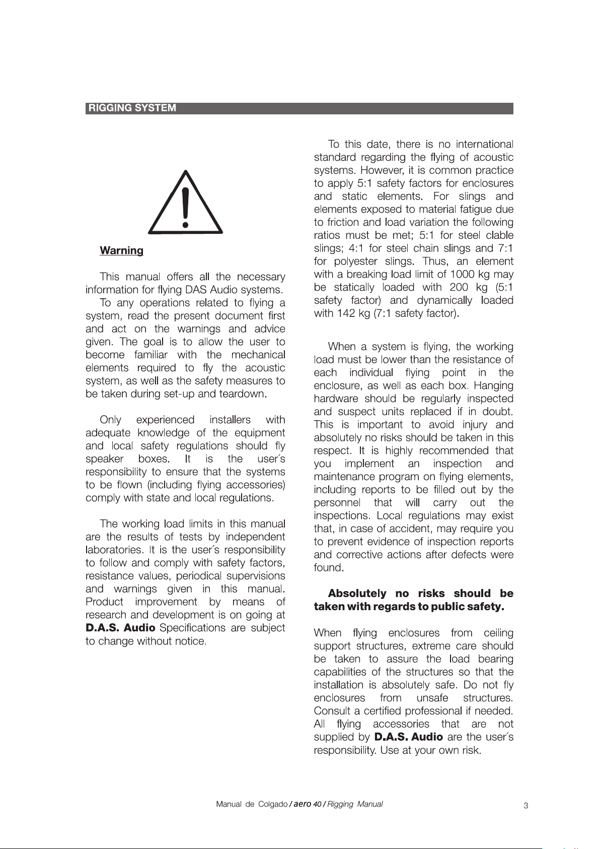
Remove the front PL-40 pushing the triggers at
the same time. Hold the carriage before acting
on the triggers. The triggers are situated on both
sides of the enclosure.
This will be the first enclosure that we will stack
onto the PL-40S.
If we look at the platform we will see the two
security pins on the sides (see figure).
These pins allow to hold the first enclosure to
the platform.
Rear part of the
PL-40S platform.
PL-40S
Security pins on
the PL-40S platform side.
Front part of the
PL-40S platform.
Side view of the PL-40S platform.
Security pins of the
PL-40S platform.
Front view of the PL-40S platform.
4
Manual de Colgado / aero 40 / Rigging Manual
Page 5
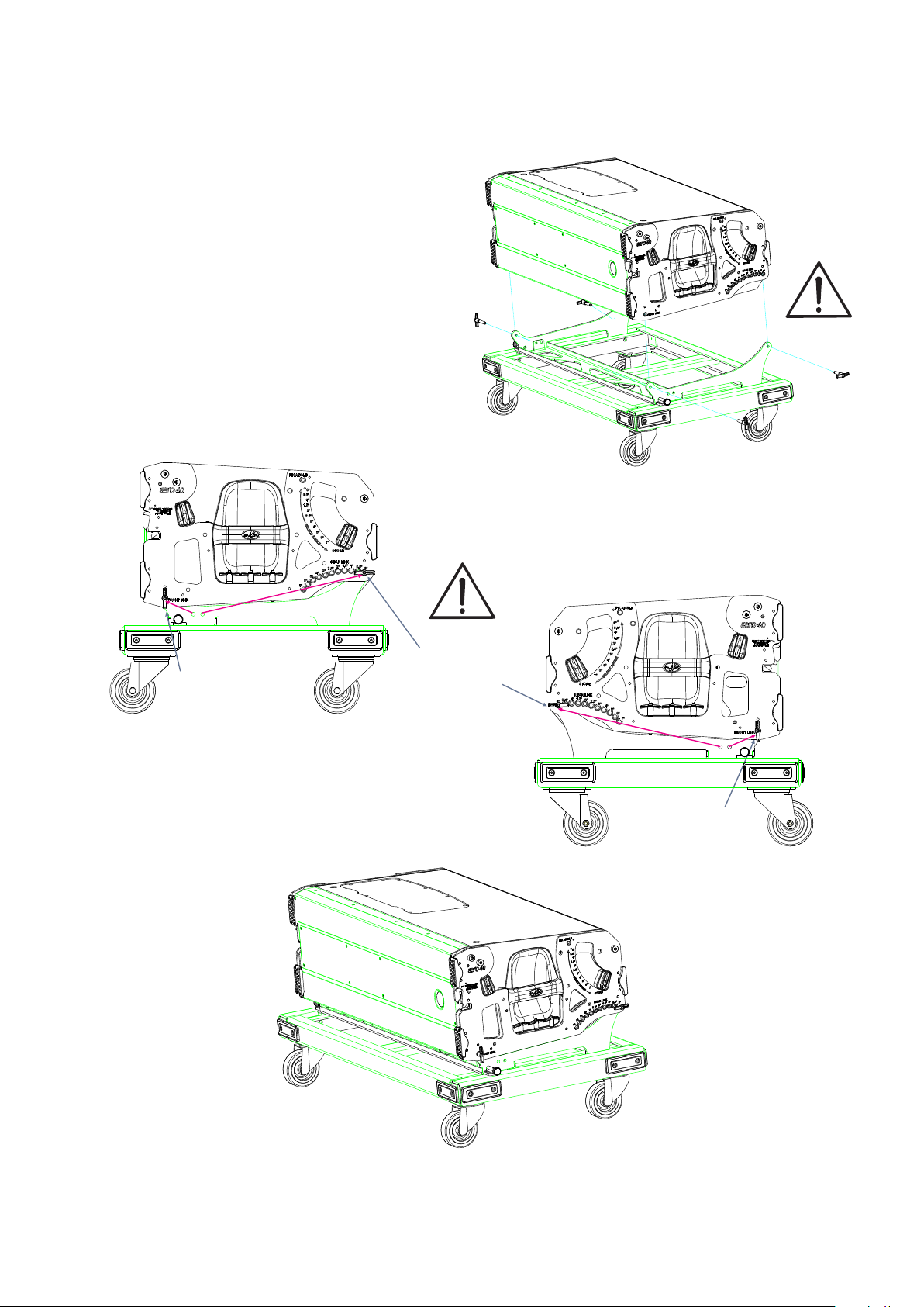
Lift the enclosure by the handles and sit
it gently over the platform.
Remove the security pins and hold with
them the enclosure.
Warning: For transport, introduce
the pin in hole 0º at “Rear Link”.
Check that the four security pins are
well positioned.
Front security pin:
FRONT LINK
Rear security pins:
REAR LINK
(Remember: 0º)
Front security pin:
FRONT LINK
Final mounting of one enclosure on a PL-40S platform.
Manual de Colgado / aero 40 / Rigging Manual
5
Page 6
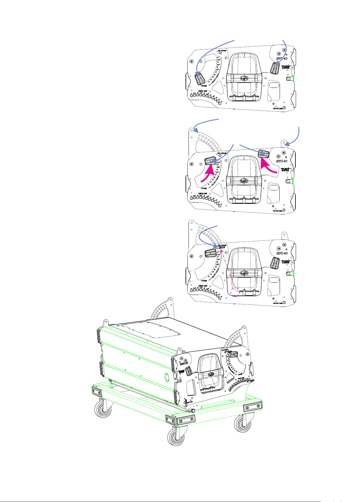
Lets add another enclosure over the previous.
We need to look at the side controls of the
enclosure and act on them like in the figure.
Side controls
The hidden front and the rear rods on the side
will appear.
The front rod will fix in its position while the rear
one can move freely.
To fix its position in 0º (position for transport),
we will put one of the security pins in the hole ‘FIX
ANGLE’ like in the figure.
The side control has arrows which mark the
selected angle, in this case 0º.
The result, platform included, can be seen in
the figures below.
Rear rods
Front rods
Side controls
Security pins
Figure of the enclosure on the platform PL-40S
with the rods ready to add another enclosure over it.
6
Manual de Colgado / aero 40 / Rigging Manual
Page 7

Lift the second enclosure and place it over the
first enclosure gently.
Remove the security pins on the sides of the
enclosure and hold the enclosure with them.
Warning: For transport, introduce the pin
in hole 0º at “Rear Link”.
Check that the four security pins are well
positioned.
Figures show final mounting of two enclosures on a PL-40S platform (side views).
Manual de Colgado / aero 40 / Rigging Manual
7
Page 8
Lift the third enclosure and place it over the
second one gently.
Repeat the process described before.
Warning: For transport, introduce the pin
in hole0º at “Rear Link”.
Check that the four security pins are well
positioned.
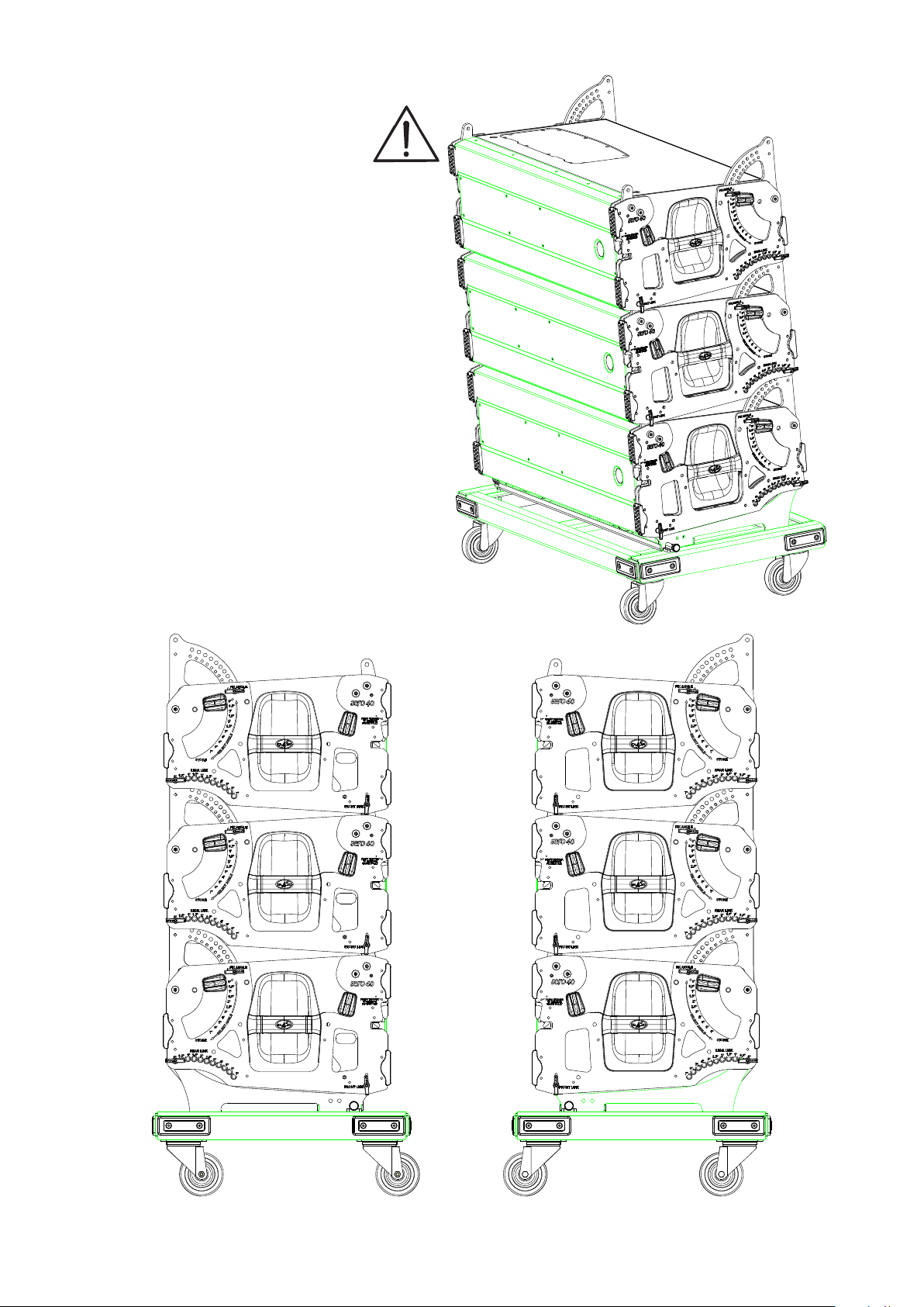
You can see the final result in the next figure.
8
Manual de Colgado / aero 40 / Rigging Manual
Page 9

Lift the fourth enclosure and place it gently
over the third enclosure.
Repeat the process described before.
Warning: For transport, introduce the pin
in hole 0º at “Rear Link”.
Never carry more than four enclosures on
the platform.
Check that the four security pins are well
positionated.
You can see the result in the next figure.
Manual de Colgado / aero 40 / Rigging Manual
9
Page 10

ARRAY MOUNTING OF GROUPS OF 4 UNITS ON A PL-40S
The groups of 3 or 4 units are easy to transport by truck.
Lets see in this section how to mount an array of four units.
Firstly, mount the AX-aero40 onto the top
box.
To mount the AX-aero40 take out the rods
of the top unit.
See the result in the right figure.
Next, place the side pieces of the AX-
aero40 introducing the security pin like in the
figure below.
Check that the security pins are well
positioned because they will support the weight
of the rest of the enclosures.
Rods
DETAIL
RESULT
10
Manual de Colgado / aero 40 / Rigging Manual
Page 11
With the help of the Ease Focus program we can
determine which point is the correct one to join the
side pieces with the bar of AX-aero40, with the
help of the security pins.
If we use two lift motors, we will use a second
Pick Up AX-aero40 which joins through the same
way to the pinpoint marked by Ease Focus.
Check that the security pins are well
positioned.
DETAIL
RESULT
Manual de Colgado / aero 40 / Rigging Manual
11
Page 12
At last, hook the lift motor. In case two lift motors are needed, hook each one to each Pick Up AX-aero40.
Like in every security operation, use adecuate security elements.
12
Manual de Colgado / aero 40 / Rigging Manual
Page 13

Proceed to assign the angles to each enclosure.
Note that the first enclosure is 0º. This is the right position for
it.
With the help of the Ease Focus program we will know the
correct angle to each enclosure. This process is similar for all the
enclosures.
1.- Take out the
security pin “REAR
LINK” of the first
enclosure.
1.
2.- Slightly
elevate the lift
motor to free the
rod.
DETAIL
2.
Manual de Colgado / aero 40 / Rigging Manual
13
Page 14

3.
DETAIL
3.- Remove the security
pin “FIX ANGLE” of the
second enclosure. Choose
the right angle with the side
control and introduce again
the security pin on “FIX
ANGLE”to fix it (2º in this
example).
DETAIL
4.
4.- Lower carefully and introduce the security
pin in “REAR LINK” and the enclosures will be
joined again.
14
Manual de Colgado / aero 40 / Rigging Manual
Page 15

We learned to assign an angle (2º) to an enclosure on
pages 13 and 14.
Now, let´s see another example for more closed
angles: 0º, 0.5º, 1 y 1.5º.
After assigning the angles to the enclosures remove
the platform to add more enclosures.
Remove the security pins and lift the group to add
another group of enclosures.
DETAIL
Manual de Colgado / aero 40 / Rigging Manual
15
Page 16

After repeating the process this will be the
result of this example, once the platform is
removed.
0º
16
0.5º
1º
1.5º
Manual de Colgado / aero 40 / Rigging Manual
Page 17

Enclosure 1
Enclosure 2
Enclosure 3
DETAILS
1.
2.
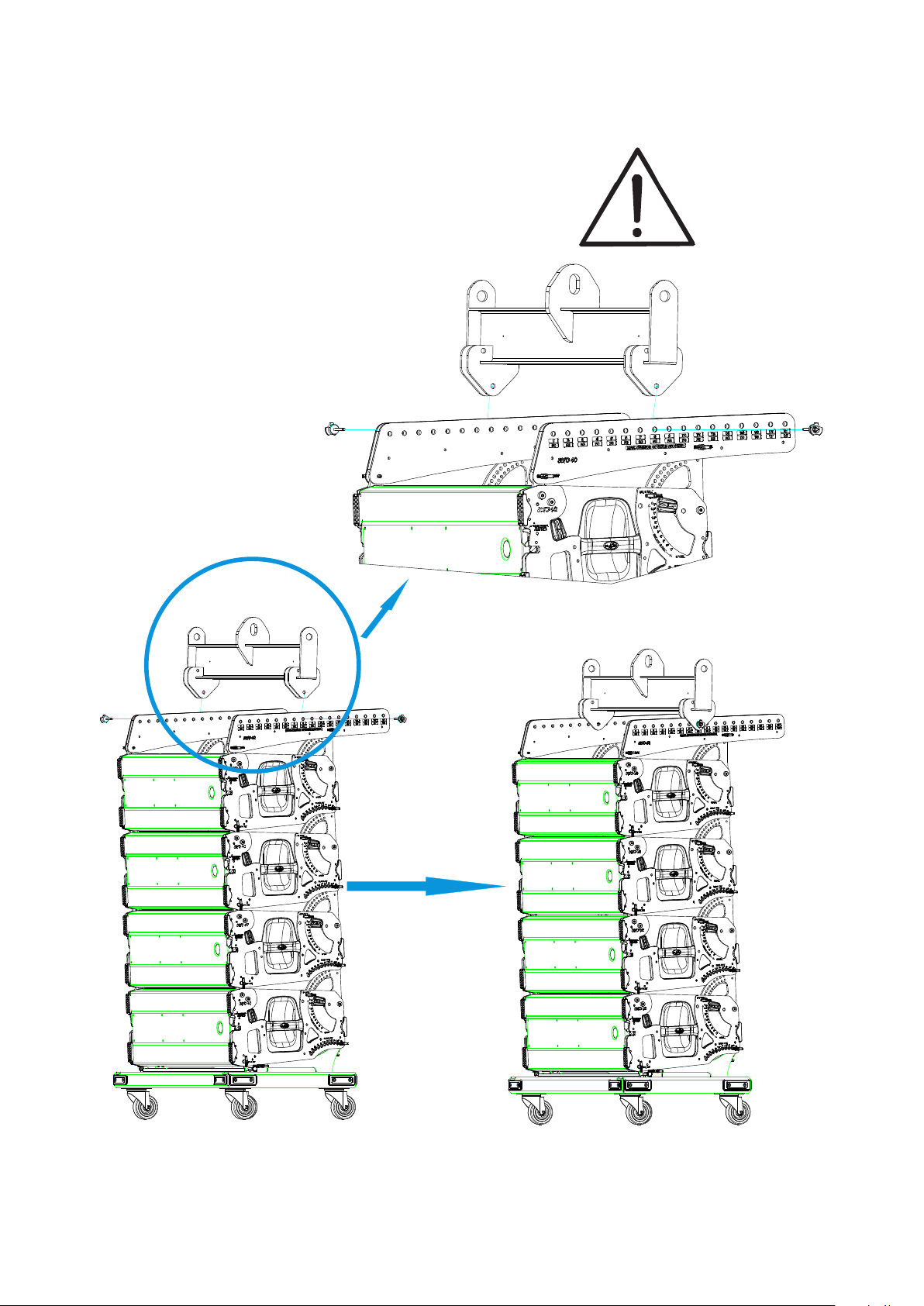
We proceed in the same
way with the next group of 4
units.
1.- Take out the rods of
the top unit. Assign the angle
to the top enclosure of the
new group and fix it
introducing the security pin in
FIX ANGLE.
2.- We go down the
group over the enclosure 5.
Enclosure 4
Enclosure 5
Enclosure 6
Enclosure 7
Enclosure 8
3.
3.- Align the front rods
and introduce the security
pins in FRONT LINK.
4.
4.- Place the top group of
4 cabinets over the bottom
group. Finally, introduce the
security pins in REAR LINK
of enclosure 4.
Manual de Colgado / aero 40 / Rigging Manual
17
Page 18

DETAIL
When the new group is joined to the top group assign the angles
following the Ease Focus instructions.
18
The assignment of the angles and to remove the platform is the same
as described before with the first group.
Manual de Colgado / aero 40 / Rigging Manual
Page 19

Here you can see the final result for this example with 8 enclosures.
0º
0.5º
1º
1.5º
2º
4º
6º
7º
Manual de Colgado / aero 40 / Rigging Manual
19
Page 20

ARRAY DISASSEMBLY OF GROUPS OF 4 UNITS ON A PL-40S
The groups of 4 units are easy to transport by
truck. In this section you will see how to
disassemble an array of 4 units.
Firstly, go down the array and align with the PL-
40S platform as the figures show.
20
Manual de Colgado / aero 40 / Rigging Manual
Page 21

Next, turn the two side pins of the platform
(see figure 1).
It allows to lift the plate of the platform.
(Figure 2).
Introduce the security pins in “FRONT LINK”
. (Figure 3).
3
1
2
Side pins
1
4
DETAIL
Support the array over the platform (4). Be
careful and avoid accidents. Use security
gloves and take care with the hands.
Use the side pins to fix the plate.
At last, introduce the security pins in “REAR
LINK.” Figure (5).
Manual de Colgado / aero 40 / Rigging Manual
5
21
Page 22

After placing the group over the platform
proceed to reset the angles to 0º because is the
safest way to transport.
As we saw in pages 13 and 14, start to assign
the angles from the top.
When you complete the group of 4 units
remove from the rest (see side figure).
This group, with 0º angulation, is easy to
transport.
Note: Push the group from the sides.
Before transport, don´t forget to hide the top
rods.
Remove the security pin from “FIX ANGLE”
and place it in “STORE”.
Referring to the front rod, move up the side
control and, holding it, push the rod (as you see in
the right figure). The control will come back
automatically to its position.
Similarly, we proceed to remove the rest of the
groups and, at last, remove the AX.
22
Manual de Colgado / aero 40 / Rigging Manual
Page 23

ARRAY MOUNTING FROM INDIVIDUAL UNITS
In this section we will mount an array from individual units and join them to form the array and rig it.
In this case, the units will rest over the front platform, PL-40, while we join them.
Add the second
enclosure at the desired angle.
(for example, 3º).
Manual de Colgado / aero 40 / Rigging Manual
Just introduce the security pin
in FRONT LINK to join them.
23
Page 24

Add the third enclosure at
the desired angle.
(for example, 4º).
Just introduce the security pin
in FRONT LINK to join them.
Repeat the process with the rest of the enclosures. In this example, we have six enclosures with the
following angles:
3º for second
4º for third
5º for fourth
6º for fifth
and 7º for sixth
24
Manual de Colgado / aero 40 / Rigging Manual
Page 25

Once all the enclosures are joined, assign 0º to the first enclosure and mount the side pieces of AXAERO40.
Make sure the security pins are well placed.
0º 3º 4º 5º 6º 7º
Join the lift motor with AX-AERO40. You will need another Pick Up AX-
AERO40 if another lift motor is used.
Manual de Colgado / aero 40 / Rigging Manual
25
Page 26

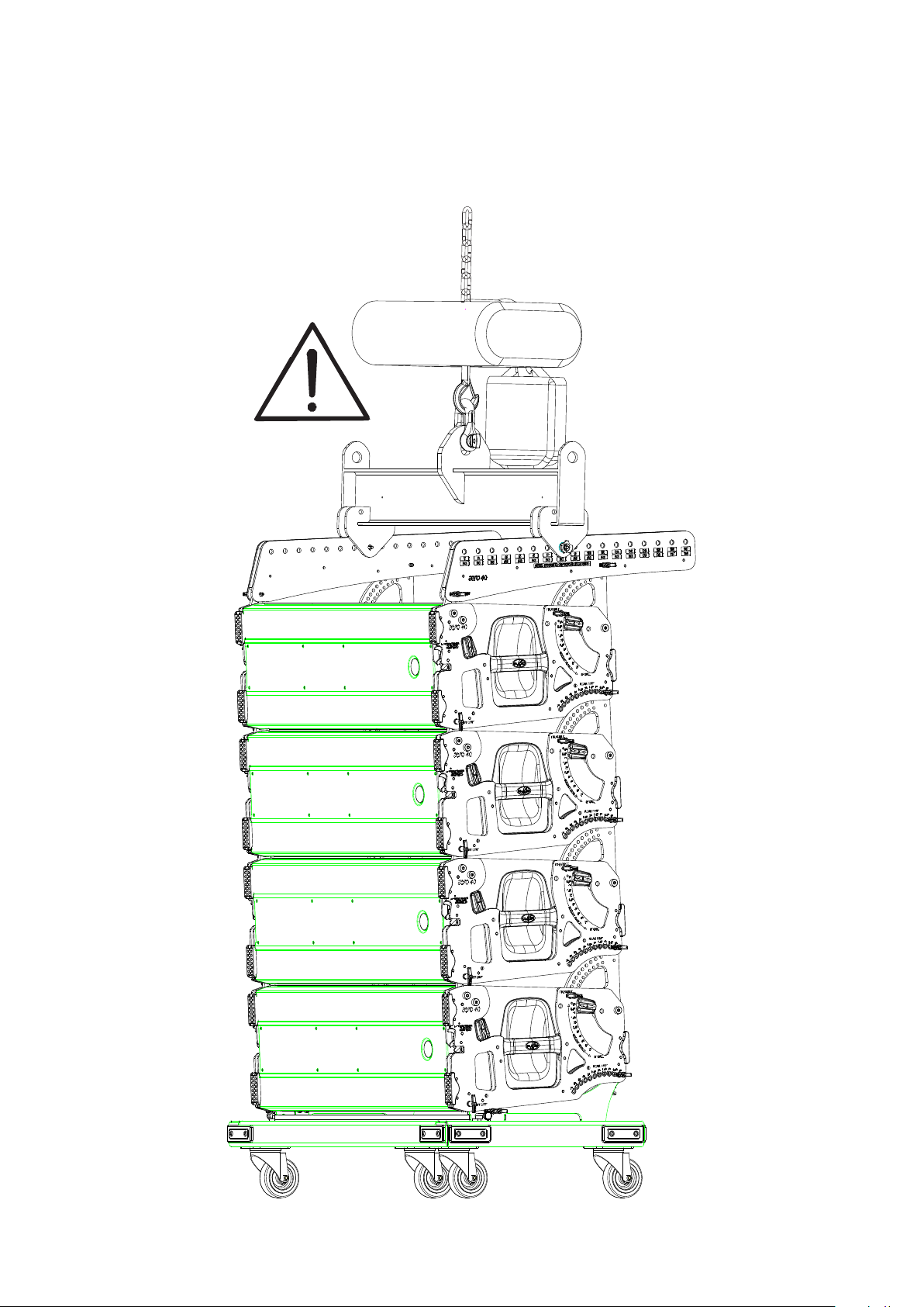
Place the AX-AERO40 and join it (with the security pins)
to the side pieces of the AX (mounted before).
After checking that security pins are well placed, start
to lift up the array system slowly.
26
Manual de Colgado / aero 40 / Rigging Manual
Page 27

While you lift the array, introduce the security pins in
REAR LINK while the holes are aligned at the desired
angles. Do this from the first to the last enclosure.
DETAIL
Manual de Colgado / aero 40 / Rigging Manual
27
Page 28

While the enclosures lift from the floor,
remove the front PL-40 acting over the
handles.
For disassembling follow the
instructions described earlier but in a
reverse way.
28
Manual de Colgado / aero 40 / Rigging Manual
Page 29

Page 30

Page 31

Page 32

Page 33

Annex I - Tools for rigging systems
For best results hanging aero series 2 systems, it is mandatory the use of Ease Focus 2
simulation software which can be downloaded for free from our website within
www.dasaudio.com
the support section. The download file contains the software and data files with gll files for acoustic
systems.
The user should be aware that any deviation in the actual installation of the system with respect to the
simulated data can affect the system’s coverage, especially in the long throw. Therefore DAS provides
clinometers and laser meters to accurately perform the installation of the system:
Leica Disto D5 Laser Meter Clinometer which is attached to the
top cabinet of the array and sensor
module. TEQSAS LAP-TEQ
Manual de Colgado / aero 40 / Rigging Manual
33
Page 34

Annex II- Maximum load capacity for AX-aero40
AX-aero40
730
430
1090
Pick Up AX-aero40
AX-aero40 is comprised of two side panels of steel and aluminum and a central bar (Pick-Up AX
aero40). It is a modular flybar set.
The maximum load capacity is 20 units * (pick-up point dependent) with a 5:1 safety factor.
For systems of 12 units or more, an additional bar should be added and the array will hang from
two lift motors for greater security and control over the angle of the system at all times.
Aero 40A load limitation: * On the side panels the maximum number of units that can be flown are
screen printed depending on the pick-up point marked by the software (or vertical axis of the center
of gravity of the system). Consulting the EASE Focus 2 software we will determine the number of
units which can be flown each pick-up point.
pick-up point
1 2 3 4 5 6 7 8 9 10 11 12 13 14 15 16 17
20202020 20 20 20 20 20 20 20 20 20 19 18 17 16
MAX. NUMBER OF UNITS ALLOWED
maximum number of units
These limitations depend on the load of the vertical axis position of the center of gravity of
the system:
From points 1 to 13 regardless of whether you use a motor or two, a maximum of 20 aero
40A units can be flown.
At point 14, 19 units of aero 40A can be flown.
At point 15, 18 units of aero 40A can be flown.
At point 16, 17 units of aero 40A can be flown.
At point 17, 16 units of aero 40A can be flown.
Pick-up point - vertical axis of the center of gravity
In the image at the right you can see the vertical axis of the center of
gravity for the system passing through the pick-up point number 11.
The pick-up point shown in the software is placed in alignment with the
vertical axis of the center of gravity for the system. The position of this
vertical axis obviously depends on the number of boxes, the angle
between them and full vertical angle. The loading limitations are
displayed by the software and depend on the vertical axis that position
the center of gravity.
pick-up point
34
Manual de Colgado / aero 40 / Rigging Manual
Page 35

For example, lets take a system of 16 aero 40A units. If we consult the
panel lettering of the AX-aero40, we observe that 16 units can be flown
when the vertical axis of the center of gravity is aligned with any of the 17
hanging positions.
1 2 3 4 5 6 7 8 9 10 11 12 13 14 15 16 17
20202020 20 20 20 20 20 20 20 20 20 19 18 17 16
MAX. NUMBER OF UNITS ALLOWED
In the simulation attached, the system is flown at 11 meters with -6.33º of
inclination. No warning of maximum load appears.
The warnings of maximum load appear ONLY if the number of cabinets
is greater than 16 units. For more than 16 units, the warnings of load
appear and we should check where the vertical axis of the center of gravity
for the system is situated.
See what happens if we add one more
box. Now we have a total of 17 aero 40A
units and the software warns us that only 17
units at point 16 or lower can be flown.
In this case, we have -5.57° of inclination,
the vertical axis of the center of gravity of the
system is positioned in alignment with the
pick-up point number 14. In this case, we
are within the safety margins. Remember
that from point 14 and above, 19 units can
be flown (see above panel drawing AXaero40).
17 aero 40A units - As the axis of the vertical center of gravity coincides
with the point 14, we can fly 17 units with that configuration.
Manual de Colgado / aero 40 / Rigging Manual
35
Page 36

Annex III - Advice for EASE Focus 2 use
SYSTEM angles (cluster):
It’s important to understand the signs of the system's total angles in the EASE Focus 2
software program.
A cluster can be flown at different angles, depending on the number of cabinets,
the angle between them and the pick-up point. The angle in the software is
defined in section View [º]
Inclining systems forwards (downwards) result in a negative angle ( ). The systems
inclined upwards result in a positive angle ( ).-+
+
Angle criteria of the cluster
-
-5º
6 aero 40A at -5º
6 aero 40A at +10º
+10º
36
Manual de Colgado / aero 40 / Rigging Manual
Page 37

Meaning of parameter DELTA EASE Focus 2:
The delta parameter marks the angle NEEDED to reach the desired angle in our system
(View [°]). This information is useful ONLY when the system is flown from a single POINT.
Imagine a system of 8 units hanging 11 meters high.
The desired angle is: View [°] -15°
As shown in the image, Delta [º] -0.62º
This means that to reach the desired -15 º, we are lacking 0.62º
when the system is flown at the point 15.
If the delta sign this indicates that we are lacking
0.62 downwards.
If the delta sign means that we are lacking
degrees upwards.
Angle criteria of delta
Now, we consider the opposite case.
This is the same system hanging from a single point. 8 aero 40A units.
The desired angle: View [°] -12°
In this case Delta [º] is 0.74
is negative (-),
is positive (+), this
+
-
This means that if we hang the system from point 14 we
lack tilt up 0.74º to reach the desired -12º.
Manual de Colgado / aero 40 / Rigging Manual
37
Page 38

DELTA parameter in EASE Focus 2 software and maximum angles:
As seen before the DELTA parameter makes a difference (in excess or in lack of) between the
desired angle and the obtained angle to hang the system from a single point.
When we fly the system from TWO points, this parameter is very useful because we also
determine the maximum angles with which we can install it.
For example, suppose a set of 12 aero 40A units:
The system is inclined -7.18 º.
Vertical axis position of center of gravity is aligned with the
pick-up point number 13.
To what maximum angle could we tilt down the system?
Suppose we want to hang the system at -17°.
Let's see what happens in the software:
Observe how Delta: -5.77º
This means that we lack to reach the
desired 5.77º, -17º.
In this case the system could only have a
maximum tilt: 17-5.77 = 11.23°
since no further pick-up points are
available on the AX-aero 40.
38
Indeed if we change the angle of the system to -11.23°, we see
that the pick-up point (vertical axis of center of gravity) is
number 17 and delta is zero. This indicates that if two lift motors
are used the system could be angled at -11.23°.
Manual de Colgado / aero 40 / Rigging Manual
Page 39

www.dasaudio.com
RM_AE40_01_EN
D.A.S. AUDIO, S.A.
C/. Islas Baleares, 24
46988 Fuente del Jarro
Valencia, SPAIN
Tel. 96 134 0525
Tel. Intl. +34 96 134 0860
Fax 96 134 0607
Fax Intl. +34 96 134 0607
D.A.S. AUDIO OF AMERICA, INC.
Sunset Palmetto Park
6816 NW 77th Court.
Miami, FL. 33166 - U.S.A.
TOLL FREE: 1-888DAS4USA
Tel. +1 305 436 0521
Fax +1 305 436 0528
D.A.S. AUDIO ASIA PTE. LTD.
25 Kaki Bukit Crescent #01-00/02-00
Kaki Bukit Techpark 1
Singapore 416256
Tel. +65 6742 0151
Fax +65 6742 0157
 Loading...