

Page 1
Manual del Usuario / User’s Guide
AERO-38 series
Page 2
®
AERO-38A / AERO-38
AERO-218A / AERO-218Sub
AERO-182A / AERO-182
D.A.S. Audio s.a.
El signo de exclamación dentro de un triángulo indica la
existencia de componentes internos cuyo reemplazo puede
afectar a laseguridad. También indica instruccionesimportantes
defuncionamientoy mantenimiento.
El signo delrayo con la punta de flecha alerta contra la presencia
de voltajes peligrosos no aislados. Para reducir el riesgo de
choqueeléctrico, no retire la cubierta.
Conserve estas instrucciones. Siga todas las advertencias. Lea
todas las instrucciones.
Aparato de Clase I. [AERO-38A, AERO-218A, AERO-182A]
Para una protección continua contra el riesgo de fuego,
reemplace el fusible únicamente con otro del mismo tipo, que se
indicaen la cubierta de la unidad.
Para reducir el riesgo de descarga eléctrica no exponga este
equipo a la lluvia, humedad o salpicaduras sin el protector de
lluviasuministradopor el fabricante.
No instale el sistema cerca del agua, piscinas y fuentes por
ejemplo.No deposite sobre él recipientes quecontenganlíquidos.
Limpie el aparato sólo con un paño seco. No use limpiadores
basadosen disolventes.
No instale el aparato cerca de ninguna fuente de calor como
radiadores,estufas u otros aparatos que produzcancalor.
El cable de alimentación suministrado con su unidad tiene
conector de tres terminales (tipo X). No corte o dañe el terminal
de tierra. Si el conector suministrado no puedeconectarse en su
enchufe, consulte a un electricista para sustituir el enchufe
obsoleto. Proteja el cable de alimentación de ser pisado o
pellizcado.
Desconecte este aparato durante tormentas eléctricas, lluvia
torrencial, terremotos o cuando no se vaya a emplear durante
largosperiodos.
No existen partes ajustables por el usuario en el interior de este
equipo. Cualquieroperación de mantenimientoo reparación debe
ser realizada por personal cualificado. Es necesario el servicio
técnico cuando el aparado se haya dañado de alguna forma, tal
como que el cable de corriente o el enchufe se hayan dañado,
haya caído líquido o algún objeto en el interior del aparato, el
aparato haya sido expuesto a lluvia o humedad, no funcione
correctamenteo haya recibido un golpe.
El colgado delacaja sólo deberealizarseutilizando losherrajesde
colgado y solamente por personalcualificado. No cuelgue la caja
delas asas. No reemplace pasadores deseguridadportornillos.
Precauciones de seguridad Safety Precautions
The exclamation point inside an equilateral triangle indicates the
existence of internal components whose substitution may affect
safety.Alsoindicatesimportantoperatinginstructions.
The lightning andarrowheadsymbol warns aboutthepresence of
uninsulated dangerous voltage. To reduce the risk of electric
shock,do not remove the cover.
Keep these instructions. Heed all warnings. Follow all
instructions.
ClassI device.[AERO-38A, AERO-218A, AERO-182A]
For continued protection against risk of electric fire replace fuse
only with same type fuse, which is indicated on the cover of the
unit.
Do not expose this device to rain, moisture or splash without
usingthe rain protector supplied by DAS.
Do not use this apparatus near water- for example, swimming
pool, fountain. Do not place any object containing liquids as
bottleson the top of the unit.
Clean only with a dry cloth. Do not use any solvent based
cleaners.
Do not install near any heat sources such as radiators, heat
registers,stoves, or other apparatus that produceheat.
The power cord supplied with your unit has a 3-pin type plug (X
type). Do not cut off or damage thegrounding pin. If the provided
plug does not fit in your outlet, consult an electrician for
replacement of the obsolete outlet. Protect the power cord from
beingwalkedonorpinched.
Unplug this apparatus during lightning storms, heavy rain,
earthquakesorwhenunusedforlong periods of time.
No user serviceable parts inside. Refer all servicing to qualified
service personnel. Servicing is required when the apparatus has
been damaged in any way, such as power-supply cord or plug is
damaged, liquid has been spilled or objects have fallen into the
apparatus, the apparatus has been exposed to rain or moisture,
doesnot operate normally,orhasbeendropped.
The applianceshouldbe flown onlyfrom the riggingpoints and by
qualified personnel.Do notsuspend thebox fromthe handles.Do
not use instead of quick release pins any other element as
fasteners.
Nuncacuelgue más cajas de las recomendadasporelfabricante. Never exceed the maximum number of units to be flown
recommendedby the manufacturer.
El doble cuadrado indica equipo de Clase 2 en sistemas de
amplificaciónexterna: AERO-38, AERO-218SubyAERO-182.
The double square indicates Class 2 device; models : AERO-38,
AERO-218Sub and AERO-182.
Page 3
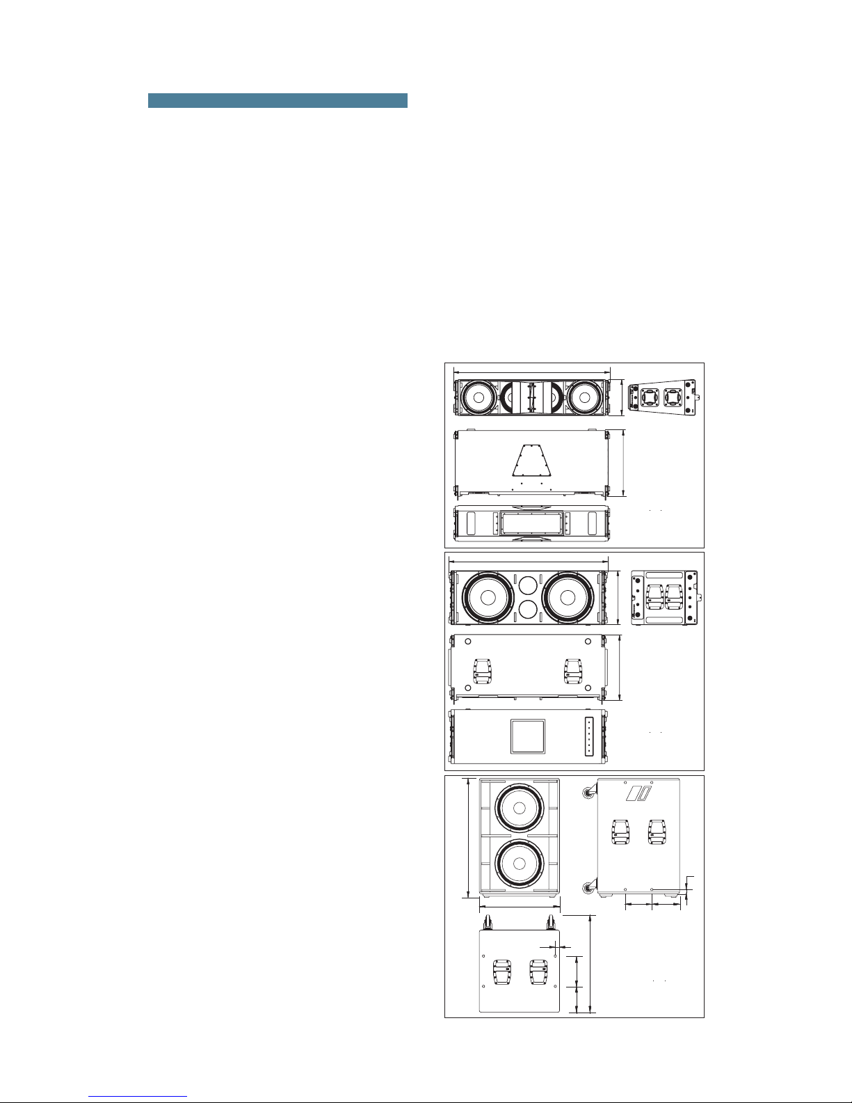
224
WARNING!DONOTSUSPENDFROMTHISHANDLE
¡ATENCIÓN!NOCUELGUELACAJADEESTEASA
WARNING!DONOTSUSPENDFROMTHISHANDLE
¡ATENCIÓN!NOCUELGUELACAJADEESTEASA
WARNING!DONOTSUSPENDFROMTHISHANDLE
¡ATENCIÓN!NOCUELGUELACAJADEESTEASA
WARNING!DONOTSUSPENDFROMTHISHANDLE
¡ATENCIÓN!NOCUELGUELACAJADEESTEASA
36
236
220
256
823
36
1010
680
AERO-218Sub
ALL DIMENSIONS IN MILIMETERS
1. SYSTEM DESCRIPTION
The D.A.S. Audio AERO series offers two
units for applications requiring precise control of the
vertical coverageand highsound pressure levels.The
AERO-38 is an externally powered, three-way, high
efficiency linearray modulewhich integrates two 12”
low frequency unitswith 4” voicecoils, two 10”midrange devices which utilize 3” voice coils and one
compression driver with 4” coil and 1.5” exit
geometry in a single unit. The compression driver is
coupled to the Serpis-38 high frequency plane wave
adaptor insuring coherent high frequency summing
and the generation of a flat, isophasic wave front.
When increased sound pressure level in the low
frequency range is required, the system can be used
in conjunction with the AERO-218Sub
subwoofer units. There are self powered version of
eachcabinet, AERO-38A, AERO-218A, AERO-182A.
The system is ideal for applications such as
large-scale outdoor/indooreventsinarenas,stadiums
or theaters. Use of the DSP-3VS digital processor is
recommended for theAERO-38 and the DS
The loudspeakers used in the system
feature advanced technologies; new TAF (
cooling systems,Neodymiummagnetic circuits
which allow forimportantweightreductions, titanium
diaphragms for the high frequencysections, and lowmid frequency cones manufactured using crossed
fibers andelasticsuspension that provideexceptional
stabilityin the vertical plane.
or AERO-182
DSP-3VS digital processor with the
AERO-38 will adversely affect the sound quality and
maydamage system components.
total air
flow)
P-1Sub
Both units are manufactured using 15/18
mm Finnish Birch plywood. The AERO-38 enclosure
shape is trapezoidal with 5º angles. The AERO218 enclosures are rectangular.
The Aero-38 and AERO-182 systems incorporate
captive rigging hardware which is compatible with
one another and designed to provide a fast, simple
and safe rigging by means of quick release safety
pins. Splay angles can be changed from 0º to 3.2º in
0.8º increments and from 3.2º to 9.6º in 1.6º
increments.
To facilitatetransport,theAERO-38units are
equipped with a PL-38 front dolly panel attached by
means of therigginghardware.Thefront dolly panelis
useful when rigging systems. The PL-48S, a metal
dolly for vertically stacking 3 to 4 AERO-38 units is
available as an accessory. The AERO-218 units
can bemoved by wayof thefour rear locatedcasters.
Also theAERO-182 system incorporatesa PL-48 dolly
panelusefullto transport the cabinet.
for
the subwoofer system(AERO-218Sub or AERO-182).
Not using the
Sub and AERO-182
Sub
The model AERO-38 includes two 12GNC
12” cone transducer with 4” EFW voice coils and
Neodymium magnet assemblies in a bass-reflex
configuration. Two 10LMN16, 10”speakersarranged
in a V shape, incorporating 3” EFW voice coils,
Neodymium magnet assemblies and TAF cooling
system are used for mid-range reproduction. High
frequencies arehandled by oneND-10 high frequency
compression driver with 4” EFW coil, Neodymium
magnet and1.5” exitcoupled to one SERPIS-38 plane
wave guide. The SERPIS-38 plane wave adaptor also
serves as a heat sink for the compression driver. The
AERO-218 include two 18GN 18”
cone transducers with 4” EFW voice coils and
Neodymium magnets. These cabinets are intended
for applications when extending the frequency range
ofthesystem is required.
Sub and AERO-182
Aero-38 Manual del usuario/ User´s manual 43
1380
316
595
AERO-38
ALL DIMENSIONS IN MILIMETERS
1400
475
580
WARNING!DONOTSUSPENDFROMTHISHANDLE
¡ATENCIÓN!NOCUELGUELACAJADEESTEASA¡ATENCIÓN!NOCUELGUELACAJADEESTEASA
WARNING!DONOTSUSPENDFROMTHISHANDLE
¡ATENCIÓN!NOCUELGUELACAJADEESTEASA¡ATENCIÓN!NOCUELGUELACAJADEESTEASA
WARNING!DONOTSUSPENDFROMTHISHANDLE
¡ATENCIÓN!NOCUELGUELACAJADEESTEASA¡ATENCIÓN!NOCUELGUELACAJADEESTEASA
WARNING!DONOTSUSPENDFROMTHISHANDLE
¡ATENCIÓN!NOCUELGUELACAJADEESTEASA¡ATENCIÓN!NOCUELGUELACAJADEESTEASA
AERO-182
ALL DIMENSIONS IN MILIMETERS
Page 4
2. RIGGING SYSTEM
2.1WARNING
Thismanual contains needed information for
flying D.A.S. Audio line array systems, description of
the elements and safety precautions. To perform any
operations related to flying the system, read the
present document first, and act on the warnings and
advice given. The goal is to the allow the user to
become familiar with the mechanical elements
required to fly the acoustic system, as well as the
safety measures to be taken during set-up and
teardown.
Only experienced installers with adequate
knowledge of the equipment and local safety
regulations should fly speaker boxes. It is the user's
responsibility to ensure that the systems to be flown
(including flying accessories) comply with state and
localregulations.
The working load limits in this manual are
the results of tests by independent laboratories. It is
the user'sresponsibility tostay withinsafe limits. It is
the user's responsibility to follow and comply with
safety factors, resistance values, periodical
supervisions and warnings given in this manual.
Product improvement by means of research and
development is on going at D.A.S. Specifications are
subjectto change without notice.
To this date, there is no international
standard regarding the flying of acoustic systems.
However, it is common practice to apply 5:1 safety
factors for enclosures and static elements. For slings
and elements exposed to material fatigue due to
friction andload variation thefollowing ratios mustbe
met; 5:1 for steel cable slings, 4:1 for steel chain
slings and7:1 polyester slings. Thus, anelement with
a breaking load limit of 1000 kg may be statically
loaded with 200 kg (5:1 safety factor) and
dynamicallyloaded with 142 Kg (7:1 safetyfactor).
When flying a system, the working load
must be lower than the resistance of each individual
flying point in the enclosure, as well as each box.
Hanging hardware should be regularly inspected and
suspect unitsreplaced ifin doubt. This is important to
avoid injuryand absolutelyno risks shouldbe takenin
this respect. It is highly recommended that you
implement an inspection and maintenance program
on flying elements,including reports tobefilled outby
the personnel thatwillcarryout the inspections.Local
regulations may exist that, in case of accident, may
require you to present evidence of inspection reports
andcorrective actions after defects were found.
Absolutely no risks should be taken with
regards topublic safety. When flying enclosures from
ceiling support structures, extreme care should be
taken to assure the load bearing capabilities of the
structures so that the installation is absolutely safe.
Do not flyenclosures from unsafestructures. Consult
a certified professional if needed. All flying
accessories that are not supplied by D.A.S. Audio are
theuser's responsibility.Useatyourownrisk.
D.A.S. Audio AERO-38 and AERO-182 line
array systems, include 2 rigging structures on each
side of the box. Manufactured from zinc plated steel
they are painted black and are affixed to an internal
plate with special crop resistant screws.Two special
stainless steel guides are assembled to each of the
structures: G1A48 (front guide) and G2A48 (back
guide), allow for stacking or flying of boxes.
To lock both guides, six (6) quick release safety pins
(supplied)must be used.
The G1A48 front guide provides a solid
connection to the box and whatever is on top of it,
while the G2A48 rear guide determines the vertical
splay angle (whether stacked or flown), as a function
ofthehole where the pin gets inserted.
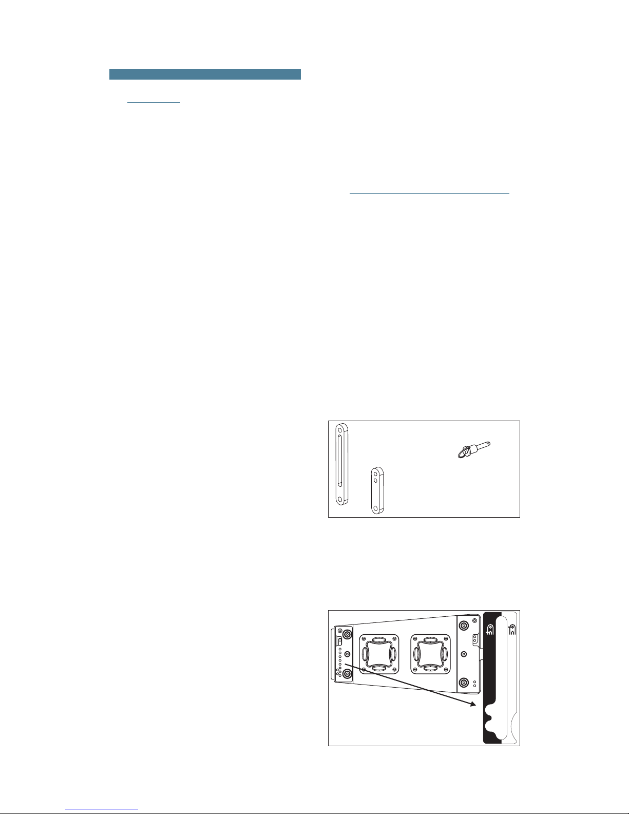
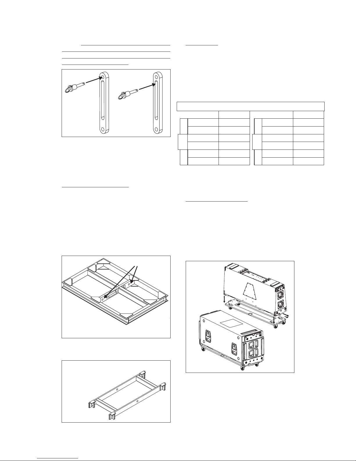
2.2 DESCRIPTION/ACCESSORIES
Splay
angles can be changed from 0º to 3.2º in 0.8º
increments and from 3.2º to 9.6º in 1.6º increments.
Aero-38 Manual del usuario/ User´s manual 44
G2A48
G1A48
QUICK RELEASE PIN 8X30
(6 UNITS PER CABINET)
To aid the setting of the G2A48 guide in the
corresponding hole inthetop box, eachholeis labeled
with an associated angle, both for stacked and flown
applications. To fit the guides into the holes, highly
resistant 8 mm quick release pins with a ball safety
lock are used.
4.8º
6.4º
8º
9.6º
3.2º
1.6º
0º
0.8º
STACK
4.8º
6.4º
8º
9.6º
3.2º
1.6º
0º
0.8º
2.4º
FLY
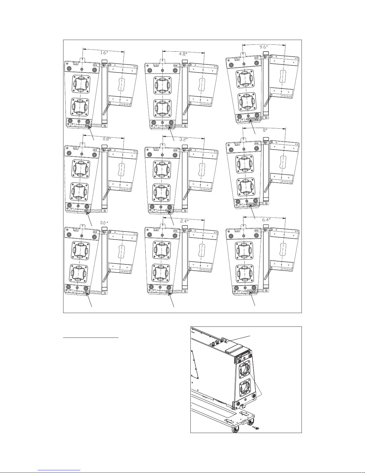
Splay angles
Page 5
STACK
FLY
For flying boxes and defining the splay
angle, thepins mustbe insertedin the of guide2,
G2A48, whereas for stacking ( ), the pin goes
throughthe oftheguide.
slot
top hole
stacked
All of theelementsneeded to rigorstack the
systems areintegral tothe enclosure(
and the quick release safety pins). The additional
items needed are the AX-AERO48 or AX-AERO38
flying grids (bumper bars), chainsand hoists, the PL38 or PL-48S dolly platforms and the AX-COMBO
G1A48, G2A48
A) AX-AERO48 and AX-AERO38
The AX-AERO48 grid is made from 100 x 50
x 6mm steel beams and is designed to handle great
loads. It features a center reinforcement bar that is
also used for the lifting slings. The force of both the
rear and the front chain hoist will determine the tilt
angle of the whole array. The structure will be
attachedto the first enclosure ofthearraybymeansof
the guides G1A48, G2A48, and six quick release
safetypins.
Weight
Dimensions: 144x93x10 cm
(HxWxD)
: 75Kg (165 lbs)
57x36.6x4 in
Pickup points
Aero-38 Manual del usuario/ User´s manual 45
The AX-AERO38grid is lighter than theother one,and
it is recommended to be used to fly a maximum of 8
cabinetsAERO-38A or 6AERO-48.
Weight
Dimensions: 147x62x10 cm
(AlxAnxP)
: 60Kg (132 lbs)
57.8x24.4x4 in
For example, if 12 units AERO-48 are going
to be flown from the AX-AERO48, each hoist to be
usedshould have a load capacity of2ton.
>750Kg
>750Kg
>750Kg
1 6units-->
1 6units-->
1 8units-->
AERO-48
AERO
182
AERO-38
AX-AERO38
AX-AERO48
>1000Kg
>1000Kg
>750Kg
>2000Kg
>2000Kg
>1500Kg
1 8units-->
1 8units-->
1 10units-->
9 16units-->
9 16units-->
11 20units-->
AERO-48
AERO
182
AERO-38
Load capacity per hoist (safety factor 10:1)
B) Chain hoists
All units in a column will be flown from the
AX-AERO48 (AX-AERO38) flying grid (bumper bar),
which should beused with twohoists, one located in
the front and the other in the rear. Each hoist should
have a minimumof1 Tonload capacity whenflyingup
8 units and a 2 Ton load capacity when flying 9 to 16
units.
C) Platforms PL-48 and PL-38
The PL-38 dolly panels facilitate transport of
the AERO-38 systems. They can also be used to
facilitate flying thesystems.Each cover isattachedto
the enclosure by using the flying hardware attached
to each box and is fixed withthe quick release safety
pins. The AERO-182 systems also include one PL-48
dollypanel per cabinet.
AERO-182
PL-48
AERO-38
PL-38
Page 6

D) PL-48S
The PL-48S platform isavaluable accessory
which allowsup to4 AERO-38 units to be transported
in astackedposition, ready tobe flown.The PL-48S is
made from steel and has 4 heavy duty casters with
lockingbrakes.
Aero-38 Manual del usuario/ User´s manual 46
PL-48S
AX-COMBO
AERO-38
AERO-28
AX-AERO48
E) AX-COMBO
The AX-COMBO is a rigging adapter to be
used when Aero-28 units are needed to be flown
under AERO-38 units asdowfill systems.Maximum 6
CA-28A unitsand8 CA-28/CA-28Bunits can beflown
from this rigging grid. The AX-COMBO includes front
and rear steel guides which permit variation of the
angle between it and the last AERO-38 cabinet in the
cluster.Anglesvaryfrom0.0ºto9.6º.
AX-COMBO
G2A48
G1A48
G2A48
Weight
Dimensions: 143x60x5cm (56.3x23.6x2in)
: 16.5Kg (36.3 lbs)
G1A48
The AX-COMBO is joined to the last AERO38 cabinet using G1A48 and G2A48 included steel
guides and 6quickreleasepins.The angle dependson
the hole of the rigging structures where the pins are
inserted, through the slots of G2A48. The first AERO28 unit is joined to the AX-COMBO using its G1A and
G2Aincludedcam links.
On the next page is a table with the angles between
both systems depending on the hole where the quick
releasepin is being inserted.
Page 7
SPLAY ANGLES USING THE AX-COMBO
F) QUICK RELEASE PINS
Each cabinet includes 6 steel heavy duty
quick release pins stored on the rear panel of the
cabinets.
Both systemsAERO-38, and AERO-182can
be flownusingsteel structures locatedon boths sides
of the cabinets. NEVER REPLACE QUICK RELEASE
PINSWITHSCREWS OR OTHERELEMENTS!!!
Pins can be used to
free the pieces
G1A48, G2A48.
Pins
Aero-38 Manual del usuario/ User´s manual 47
Page 8
2.3 SAFETY FACTORS
breaking load limit and the
maximum safe working load limit (SWLL). In this
case, the breaking load limit of each of the flying
points is 4,000 kg (8,820 lbs) as determined by
destructive testing in independent laboratories. With
a 10:1safety factor,a totalamount of 1,600kg (3,527
lbs) can be flown from the 4 flying points. Each flying
point has a capacity of 400 kg (882 lbs) with a 10:1
safetyfactor.
The safety factor is defined as the
coefficient between the
T
Theuse of two hoists withaloadcapacityas
expressed on the previous page is mandatory. It
should be kept in mind that at certain moments, the
complete load may be supported by only one of the
hoists.
he maximum number of AERO-38 units
that can be suspended from the AX-AERO48 flying
grid is 20 (with 10:1 safety factor). T
The
maximum limits established by the manufacturer
shouldneverbe exceeded.
This is why the load capacity of the individual
hoist must be superior to the weight of the array
column.
NOTE: The rigging systems of the AERO-38 and the
AERO-48 are compatible. Some accessories (AXAERO38,AX-AERO48)can be used by both systems.
he maximum
number of AERO-182 units that can be suspended
from the AX-AERO48 flying grid is 16 (10:1).
Aero-38 Manual del usuario/ User´s manual 48
4 x 400Kg (10:1)
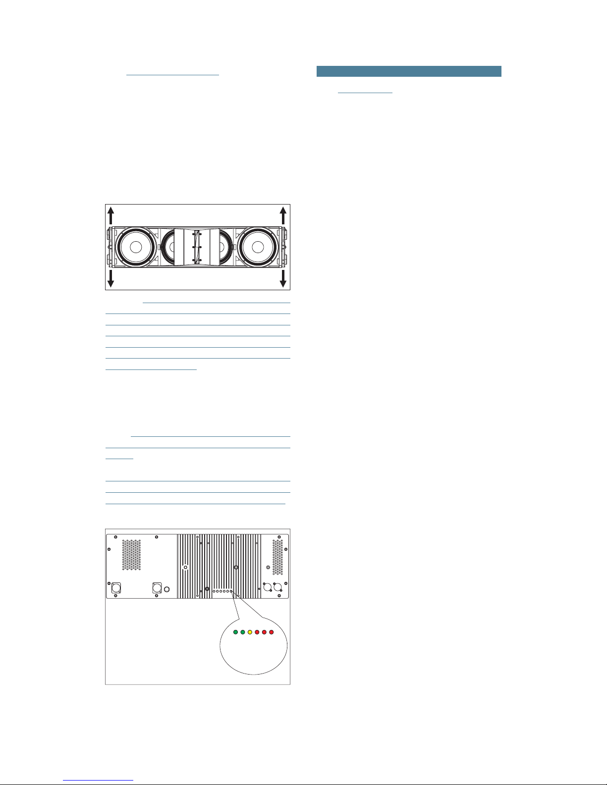
3.1 AERO-38A
3. SELF-POWERED SYSTEMS
The Aero-38A is a three way, class D, self
powered system.
Nominal amplifier power (RMS) per way:
LF:1000W MF: 500W HF:500W
Amplifierpanel description:
A) : A
B) :
C) :
E) .
F1) :
F2) :
6 (at 230V)
G) :
1=GND(ground)
2=(+)Non inverted input
3=(-)Inverted input
H) :
LIMIT
SIGNAL
ON
FUSE
AC INPUT
AC OUTPUT
INPUT
LOOP THRU
D) : Indicatesthatthe amplifier
is underprotection mode because damage riskdue to
shortcircuit or extreme working temperature.
PROTECTION
mplifier limiter indicator lights.
When lit, the level of the signal source should be
reduced.
Signal presence indicator at the
amplifiers'inputs.
Indicator light for each amplifier
channel.
With PowerCon NAC 3 FCA
connector. Only when the connector is inserted and
rotated (clicked) into place will the AC turn on. The
connector can be used as a switch, rotating the
connector to or from the locked position will turn the
unit on oroff, respectively. Mutethesignalfeedingthe
beforeturning the unit on or off.
With (white) PowerCon
NAC 3 DFCB connector. This is used as an AC loop
thru so thatupto boxes can be powerfrom
asingle AC line.
Balanced signal XLR. Pin
assignmentsas follows :
Used for paralleling several
units, which willsharethe sameinput.The output can
also be used to provide signal for an outboard power
amplifier.
INPUT
Rear panel of the AERO-38A amplifier.
F2-PowerCon NAC 3DFCB
HF
G-Input XLR
E-Fuse
H-Output XLR
F1-PowerCon NAC 3FCA
SIGNAL
MF
LF
ON
PROTECTION
DAAAB
ZOOM
H
G
F1
E
F2
C
Page 9
Low frequency mono-amplified system.
Nominal amplifier power (RMS) 1000W.
Amplifierpanel description:
mplifier limiter indicator lights.
When lit, the level of the signal source should be
reduced.
Signal presence indicator at the
amplifiers'inputs.
Indicator light for each amplifier
channel.
With PowerCon NAC 3 FCA
connector. Only when the connector is inserted and
rotated (clicked) into place will the AC turn on. The
connector can be used as a switch, rotating the
connector to or from the locked position will turn the
unit on oroff, respectively. Mutethesignalfeedingthe
beforeturning the unit on or off.
Balanced signal XLR. Pin
assignmentsas follows :
Used for paralleling several
units, which will share the same input. Could also be
usedto provide signal for an outboardpoweramplifier.
H) : Used to control the
subwoofer level. To prevent accidental mis-setting, a
flat-blade screwdriver isneeded to rotatethe control,
which is recessed and detented. Depending on the
sensitivity, placement and configuration of your midhigh system, you may need to adjust this control for
balancedfrequency response.
INPUT
SUB LEVEL
NOTE: The amplifiers on the AERO-218A
and AERO-182A systems do not inlclude a filtered
satelliteoutput for AERO-38A systems.
A) : A
B) :
C) :
D) .
):
F) :
1=GND(ground)
2=(+)Non inverted input
3=(-)Inverted input
G) :
LIMIT
SIGNAL
ON
FUSE
E AC INPUT
INPUT
LOOP THRU
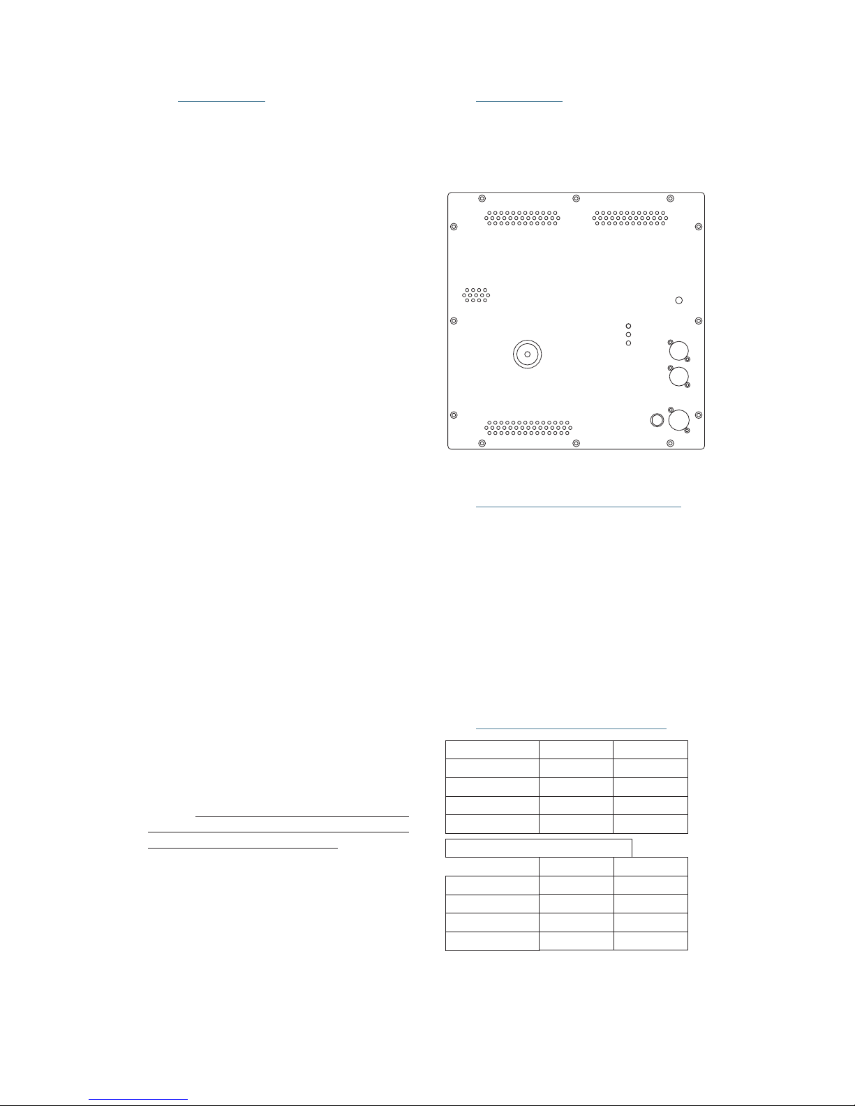
3.2 AERO-182A
The required voltage for all models is:
115V, 50Hz/60Hz - 230V, 50Hz/60Hz
Maximum voltage (divide by 2 for115V):
264V
Shutdown voltage (divide by 2 for 115V):
Aero-38A: 156V
Aero-182A / Aero-218A: 160V
3.5 CURRENT CONSUMPTION
F
D
H
G
A
C
B
E
Amplifier panel on AERO-218A and AERO-182A
systems.
3.3 AERO-218A
The Aero-218A is a low frequency monoamplified system.
Nominal amplifier power (RMS) 2 x 1000W.
3.4 AC POWER REQUIREMENTS
AERO-182A / AERO-218A *
Maximum Power
AERO-38A
Maximum Power 8A
Sine 85Hz
2.5A
Pink noise
1/3 Power
3.2A
1/8 Power
1.6A
Idle
0.25A 0.25A
Data obtained at 230V, multiply per 2 for 115V.
*For 2000W versions multiply per 2.
Maximum power: Measured in conditions of severe
clipping.
1/3 Power
1/8 Power
Idle
Aero-38 Manual del usuario/ User´s manual 49
7A 2.5A
Sine 50Hz Pink noise
3.0A
----
----
1.1A
0.1A 0.1A
----
----
Page 10
A sound system should be switched on
sequentially. Switch on the self-powered unit last in
your sound system. Switch on the sound sources
such asCD players or turntables, then the mixer, then
the processors, and finally the self-powered unit. If
you have several units, it is recommended that you
switchthem on sequentially one at atime.
Follow the inverse orderwhenswitchingoff,
turning self-powered units off before any other
elementin the sound system.
Mute all signalsourcesbefore switchingthe
unitonor off.
It is recommended that the red LED
indicators are not lit continuously; at most it should
blinkonlyoccasionally.
If you wish to have a visual indicationat the
mix position of whether the LIMIT LEDs are lighting,
during equipment set-up, closely observewhat mixer
VUmeter level corresponds to the level that lightsthe
enclosure's LIMIT LEDs. That level that should not be
exceededduring the event.
LIMIT
Due to their highefficiency, the Aero Series
amplifiers generate very little residual heat and
therefore do not need a fan for cooling. In normal use,
theamplifier panel will be warm tothetouch.
If theunit stopsplaying (orjust the mid-high
or the bass sections), the amplifier's overheating
protection may be activated to protect the
componentsfromthermal damage.
Overheating may be due to insufficient
cooling, or to very aggressive use in extremely hot
conditions. Do not use the unit in proximity to high
powerlights.
Once the amplifier cools down, it switches
back on automatically. If the unit should shut down
again, try reducing the volume a notch to avoid
overheating.
3.7 INDICATORSOVERLOAD (LIMIT)
3.6 SWITCH ON-OFF
3.8 OVERHEATING
3.10 LOW MAINS VOLTAGE
If mains voltage falls below the shutdown
voltage for the unit, it will stop playing. When
acceptable levels are regained, the unit will switch
backon automatically.
3.9 ECUALIZATION
The AERO-38A can be used full-range. Fullrange use is only recommended for applications
where low SPL level and no bass reinforcement is
adequate. To use it in thismode simplyplug themixer
intothe enclosure's input.
The most common use will be combined
with the AERO-218A (AERO-182A). In this case
different outputs of the mixing console will be used
with theAERO-38A and theSUBS.Both subsystems,
AERO-182A andAERO-218A includesignal treatment
in the amplifiersextendingtheir frequencyrangeup to
85Hz. As well, the amplifier of the AERO-38A
incorporates signal treatment which provides
frequency range extension down to 60Hz. Due to this
overlap between 60-85Hz the use of an
to control and adjust the phase of the subs
external
delay is
recommended.
3.11 CONNECTIONS
AERO-38A
Mezclador/Mixer
Retardo/
Delay
AERO-182A
Procesador/
processor
The connector isanoutput XLR
in parallel with the input connector and is useful for
daisy chaining the input signal to a number of boxes,
connectingthem in parallel.
The number of units that can be linked this
way depends on the output impedance of the
equipment drivingthe enclosure, suchas themixer or
processor. Typically, to avoid signal degradation, the
maximum number that can be daisy chained is given
by the formula Zc>10Zs, where Zc is the load
impedance and Zs is the output impedance of the
equipment driving theenclosure(mixer,console,etc).
For instance, a mixing console with 100 ohm output
impedance allowsdaisy chaining20 boxes,when the
inputimpedance of the cabinets is 20Kohm.
LOOP THRU
Aero-38 Manual del usuario/ User´s manual 50
The units do not need extreme EQ. Avoid
high levels of gain on the equalizers. Gain values
above +6 dB on a console's EQ are not
recommended.
Page 11
Aero-38 Manual del usuario/ User´s manual 51
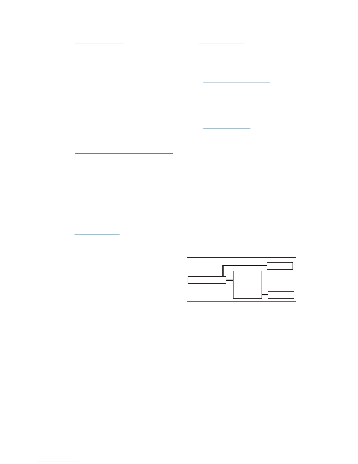
As can be seen in the diagram, independent signal lines exist for the subwooferunits, AERO-182A. The signal that
goesto the subs is processed bymeansoftheDSP-1Sub to adjust the delay betweenbothsystems.
3.12 RAIN PROTECTOR
Electronic devices can be damaged when
exposed to water or moisture. AERO-38A and AERO182A/218A amplifiers must be protected when
installed outdoors. A rain protector is supplied with
eachAERO-38A and AERO-182A/218Aunit.
The rain protector is specially designed to
withstand soft rain and other meteorological
conditions for short periods of time. In the case of
heavy rains, storms or permanent outdoors
installations the sound system must be protected
withadditional elements.
The rain protectors supplied with each unit
havebeen manufactured with fireproof materials.
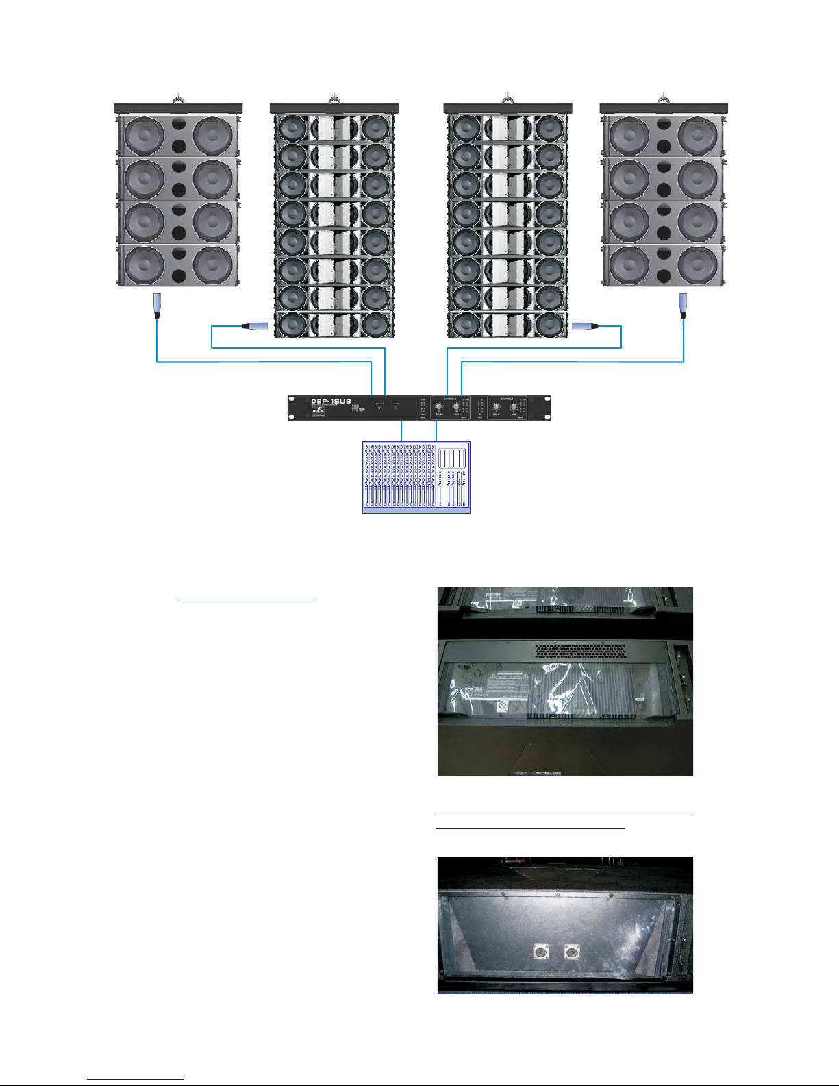
The AERO-38A's rain protector features
severalsmall holes on thetopsidetoallowconvection
coolingofthe amplifier.
AERO-38 rain protector.
NOTE: Therain protectorof the AERO-38A is different
fromtheone that includes the AERO-38.
AERO-38A rain protector.
Page 12
3.13
HOW TO MAKE A PASSIVE
SYSTEM INTO A SELF POWERED ONE.
This way the amplifier of the AERO-38A
systemhas been correctly installed in thebox.
convert
loosen
r.
remove 14 x
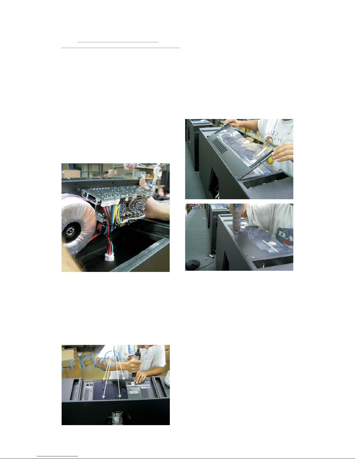
AERO-38 -->AERO-38A:
AERO-38 passive systems come with a
metallic backplate, protectedby arain protector, that
features two Speakon NL8 connectors. To a
passive system into an active one, firstly the
screws 11x (3.9x19Pv00) and therainprotecto Once
this has been done, the M4x20 screws
thatfix the back plate to thebox.
On the rear side of the backplate the cables
coming from the Speakon connectors lead to a white
male connector, which is inserted in a white female
connector attached to the box. Unplug the male
connector coming from the Speakon connectors and
insertthe male connector oftheamplifierinthefemale
connectoronthe box.
The fourM4x30 DIN7985 mustbe screwed
in thefour holesthat can be seen onthe radiatorarea.
The white arrows in the picture above point to the
mentionedholes.
Different rain protectors are needed for the
passiveand the active versions!!!
The rain protector for the self powered
version is supplied with the amplifier. In order to
attach it to the box just rest the protector on the
receptacleand retighten the eleven 3.9x19PV00 on.
The white connector mentioned above can
be plugged only in one way, so a mistake in the
connections is mechanically impossible. Make sure
that the connection is tight enough, then put the
amplifier in its receptacle paying attention that wires
donotget caught.
The next step will be to fix the amplifier to
thebox with the screws supplied:
10x(M4x20 DIN 965)
4x(M4x30 DIN 7985)
Aero-38 Manual del usuario/ User´s manual 52
Page 13

Aero-38 Manual del usuario/ User´s manual 53
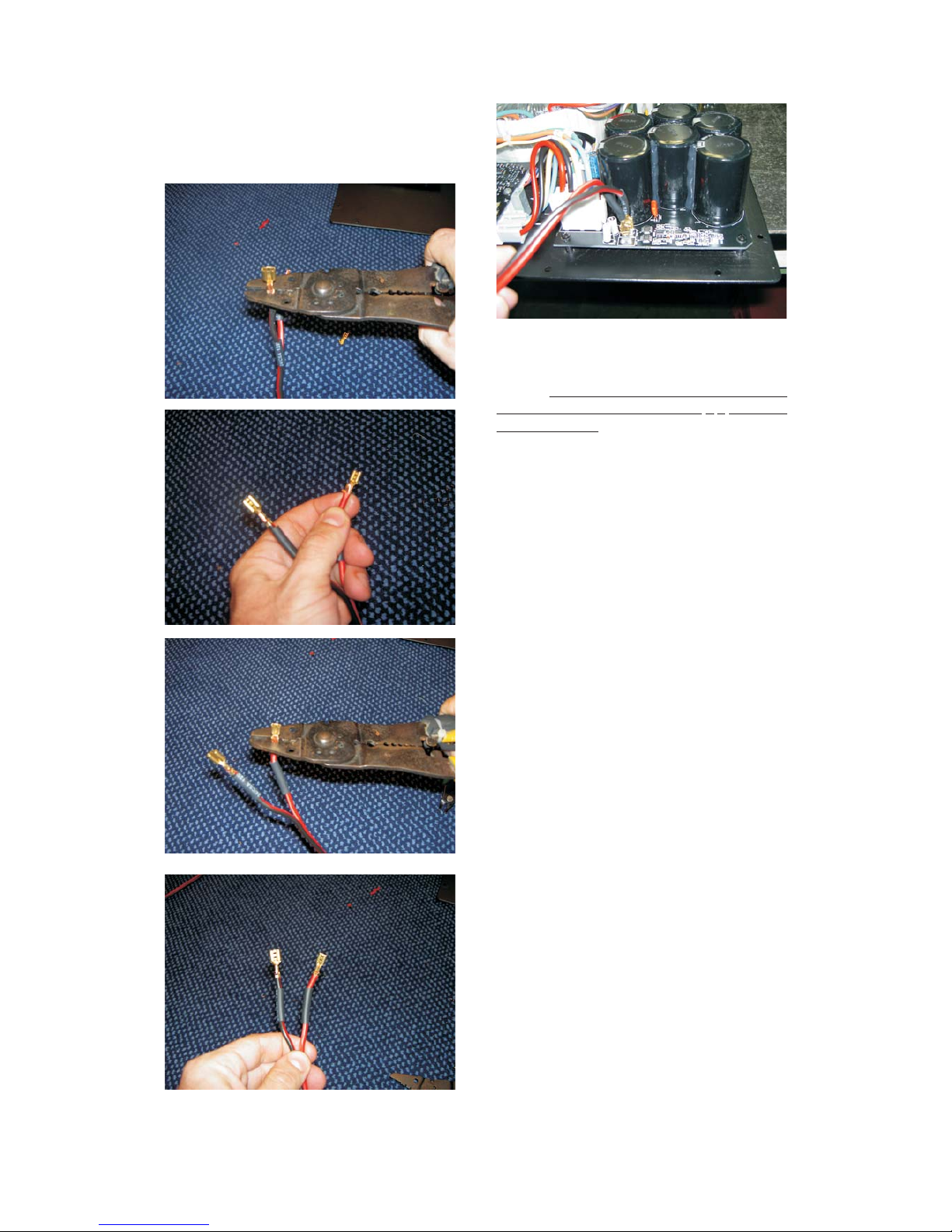
AERO-218Sub -->AERO-218A
To make a passive system into an active
one, firstly the back plate must be removed by
unscrewingthe 12 M4x20 DIN965.
After cutting the speakers' wires on the
circuit board, terminals mustbeattachedtothe
speakers' wires as follows: to assure current polarity
attach large 6.3mm female terminal to the
black wire, and a smaller 4.8mm female
terminal to the red wire. Connecting the terminals to
the correct male terminals on the amplifier circuit
boardamplifie, the polarity will be correct.
faston
faston ,
faston
It is highly advisable to shield the terminals
withtape or thermoretractable material:
Thenthe speaker wires must becutfromthe
circuitboard.
NOTE: As AERO-218A and AERO 182A
amplifiers' polarity is inverted referenced to that of
conventional external amplifiers, the polarity of the
speakers' wires must be changed when switching
fromapassive to an active AeroSeriessub.
-
Page 14
Aero-38 Manual del usuario/ User´s manual 54Aero-38 Manual del usuario/ User´s manual
The large terminal
should be attached to the black wire, and the small
terminal should beattachedto the
redwire:
faston
faston
6.3mm wide
4.8mm wide
In the case of the AERO-218A the same
processapplies to the second amplifier inthebox.
Should you have any problem during this
process do not hesitate to contact D A S factory or
ourregionaldealer.
...
Page 15

Aero-38 Manual del usuario/ User´s manual 55
PROBLEM CAUSE SOLUTION
1- Turn down the mixer's output.
3.14 TROUBLESHOOTING
No sound from the unit.
The presence LED
indicator(s) do(es) not light up.
SIGNAL
1- The signal source is sending
no signal.
2- Defective cable.
1- Check that the mixer or sound
source is sending signal to the UNIT.
2- Check that the cable from the
sound source to the UNIT is
connected correctly. Replace the
cable if defective.
Full power cannot be obtained.
The LED indicator(s) never
light(s) up.
LIMIT
1- The signal source does not have
a hot enough output.
1- If using a mixer, use the balanced
output if available. Use a professional
mixer with a hotter output.
Sound is distorted.
The LED indicator(s) is/are not
on, or only light up occasionally.
LIMIT
1- The mixer or signal source
is distorting.
1- Turn mixer channel gains down.
Check that none of your signal
sources are distorting.
Sound is distorted and very loud.
One or more LED indicators
light up.
LIMIT
1- The system is overloaded and
has reached maximum power.
Hum or buzz when a mixer
is connected to the unit.
1- The console probably has
un-balanced outputs. You may
be using an incorrect un-balanced
to balanced cable.
2- The mixer and the powered
speaker are not plugged into
the same mains outlet.
3- The audio signal cable is too
long or too close to an AC cable.
1- Read the appendix of this manual
to make a correct un-balanced to
balanced cable.
2- Connect the mixer and the unit
to the same mains outlet.
3- Use a cable that is as short as
possible and/or move the audio
signal cable away from mains cables.
Hum or buzz when using lighting
controls in the same building.
1- The audio signal cable is too
long or too close to the lighting cable.
2- On a sound system with threephase AC, the lighting equipment
and the UNIT are connected to
the same phase.
1- Move the audio signal cable away
from lighting cables. Try to find out
at what point the noise is leaking
into the system.
2- Connect the sound system to
a different phase than the lights.
You may need the help of an electrician
The power on LED indicator(s) do(es)
not light up when the power connector
is rotated and locked at the
ON position.(LOCK)
1 Bad or loose AC connection to
the UNIT or the mains outlet.
2 Faulty AC cable.
3 Blown Fuse.
1- Check you connections.
2- Check the cables, connectors
and AC power with a suitable
mains tester.
3- Replace fuse on fuse holder with
one of the same type. If it blows again,
take the unit to a service centre.
Page 16

4. ASSEMBLING AN ARRAY
4.1TRANSPORTING THE CABINETS
AERO-38 units can be transported by using
the front paneldollyPL-38orbyusing the PL-48S steel
dolly which can transport a maximum of 4 AERO-38
stacked.
The AERO-218Sub can be transported on
the rear located casters. Their rectangular shape
facilitates ground stacking without the use of the
rigging hardware. The AERO-182 cabinets can be
transportedby using the front panel dollyPL-48.
4.2 PLANNING/INSPECTION
4.3 ASSEMBLING AN ARRAY “ONE
BY ONE”
When few units are to be used (minimum
systems recommended is 6 units) or when the dolly
platforms cannot be used due to a lack of space, the
enclosures will havetobehung “one byone”.The first
step will be to attach the AX-AERO48 or the AXAERO38 grid structure to the hoists. The chain slings
need to be attached to the structure using the
shackles provided with the grid. Once this has been
accomplished, the grid structure can be placed in a
vertical position by lifting the rear hoist and lowering
the fronthoist sothat therear ofthe gridis ontop and
the front ofthe grid atthebottom, readytoreceive the
first box rolled into place by means of the PL-38 dolly
platform.
The nextstep isto attach the first unitto the
grid by introducing the G1A48 and G2A48 guides in
the receivingpoints of the grid structure and assuring
them with the six safety pins. The safety pins should
be inserted in the slot of the G2A48. It is very
important to make sure that the pins have been
insertedand lockedcorrectly.
Once the first unit of the array has been
attached to the AX-AERO48 or AX-AERO38, the
assembly should beliftedbywayof the rearhoistuntil
the wheels of the PL-38 dolly platform lift off the
ground. From thispoint on, thefront hoist canbe used
toliftthe box into a horizontal position.
Before installing the AERO systems it is a
good idea to run a simulation using the AEROWARE
program utilizing thevenue dimensions. Thisway we
can determine the needs that should be met by the
rigging structures such as hoists, cranes, beams,
rigging points, etc. Besides providing weight
information, the program also provides users with
splay angle information, safety pin positions and
coveragepredictions.
Inspection is the next step after planning
and acquiring all the necessary parts needed to
elevate the systems.Allparts, includingthehardware
attached to the enclosure,thesafetypins, etc. should
be thoroughly inspected before each use. Units
exhibiting deformations, cracks or any other defect
shouldbe replaced with new units.
It isextremelyimportant to assurethat each
and every one of the aforementioned structures is
capable of supporting a superior load than that of the
completesystem.
It is important to establish an inspection
routine for the complete rigging system before each
event or installation as well as establishing the
maximumloadspecifications of the hoists tobeused.
Rigging should be carried out by experts
familiar with the way the systems function and their
characteristics.
On occasions, it may be convenient tohave
additional tie down points to impede the array from
twistingor swinging.
Aero-38 Manual del usuario/ User´s manual 56
AX-AERO48 (AX-AERO38)
1
2
3
4
5
6
Quick release pin must be
inserted thru the slot of G2A48.
3y4
Same process for AERO-182
AERO-38
Page 17

Once thefirst boxhas been placed at 0ºand
raised approximately 75cm (30 in) the second box of
the array can be rolled into place. Once located in
position, the G2A48 guides of the second box should
be freed and inserted in the rear located receiving
points of the suspended box and secured with the
safetypins.
Swing the G2A48 guide
into place and secure it
with the safety pin.
Once the splay angle between the first two
boxes has been determined, the front of the box can
be lifted into place. Three people will be needed to
undertake this operation,twoto liftthebox and oneto
fitthe G1A48 guide and safety pinsintotheupperbox.
57Aero-38 Manual del usuario/ User´s manual
Lifted by way of the rear hoist
until the wheels of the PL-38
dolly platform are off the ground.
Lift with the front hoist
until the box is in a
horizontal position.
0º
Lift the box and free
the G1A48 guides.
Page 18

AX-AERO48 (AX-AERO38)
1
2
3
4
5
6
Quick release pin must be
inserted thru the slot of G2A48.
3y4
AERO-38
Once the boxes have been joined, the front
dolly panels can be removed. The next boxes should
be attached “one by one” using the methods
described. Finally, the array should be hoisted to the
correct height and secured with slings to avoid
swinging. This method is more time consuming than
assembling an array by the “all at once” procedure,
but isappropriate for situations due to a lack of space
in which to array the system. During the process, the
safety pins should be checked making sure they are
secured correctly. Once the complete array has been
lifted into place, additional slings should be attached
tosecure the array and avoid swinging.
AERO-182 systemscanbe flown onebyone
asdescribed previously!!.
4.4 ASSEMBLING AN ARRAY USING
THE PL-38 PLATFORM
The PL-38 platform can be used to easily
transport AERO-38 units to the assembling area. To
use thismethod of assembling and hoisting the array,
there must be enough space to permit linking all the
boxesfromthe front of the the rigginghardware.
The first step will be to attach the AXAERO48 or AX-AERO38 grid and the 2 hoists. Once
this hasbeen accomplished,the gridstructure can be
placed in averticalpositionbylifting the rearhoistand
lowering the front hoistsothattherearofthegrid is on
top and the front of the grid at the bottom, ready to
receivethe first box.
Rigging points
The nextstep is toattach thefirstunit tothe
grid by introducing the G1A48 and G2A48 guides in
the receivingpoints of the grid structure and assuring
them with the (6) safety pins. The safety pins should
be inserted in the slot of the G2A48. It is very
important to make sure that the pins have been
insertedand lockedcorrectly.
58Aero-38 Manual del usuario/ User´s manual
Lift the box and introduce the
G1A48 guides securing them
with the safety pins.
Page 19

Once the first box is attached to the
structure, the remaining boxes should be brought to
the array andattachedrepeatingtheprevious steps (1
and 2) using G1A48 guides and safety pins per side
making sure that the pins have been inserted and
lockedcorrectly.
Proceed toattach the remaining units inthe
same manner until all the array units are attached to
one another. For example, if we are assembling a six
unit array, the process will be repeated six times.
When allthe unitsare attached,the completearray is
readyto be hoisted.
When the rear of the enclosures come
together,the G2A48 rear guides should be positioned
(4) into the hardware of the box above, inserting (5)
the safetypins in the correct angleposition. Sincethe
boxesare flown, the safety pinsshouldbeintheslotof
theG2A48guide.
As the array assembly is lifted (6 & 7), the
PL-38platformsshouldberemoved.
Once thecompletearray hasbeenlifted into
place, additional slings should be attached to secure
thearray and avoid swinging.
The front motor will be used only to take up
slack inthe chain,all the weight should be on the rear
hoist. When the wheels of the last enclosure are off
thegroundthe array can be liftedwithbothmotors.
59Aero-38 Manual del usuario/ User´s manual
The complete assemblyshould begin being
lifted from the rear hoist (3) so that the rear of the
enclosures come together due to their trapezoidal
shape. The front motor will be used only to take up
slack inthe chain, allthe weightshould be on the rear
hoist. Proceed in this manner until the wheels of the
last enclosure are off the ground. From here on, the
arraycan now be lifted with bothmotors.
G1A48
2
1
G2A48
3
4
5
Rear hoist!!
7
6
Rear hoist FIRST!!
Page 20

Manual del usuario/ User´s manual 60Aero-38
Page 21

While the array assembly descends, the
rear of the enclosures will come together, at that
moment, the safety pins which hold the G2A48
guides in place should be removed. Once removed,
the guides should be swung back into the box they
belong to. Finally, the boxes should be totally
detached from one another by releasing the G1A48
guide.
To lower the system, both hoists should be
used until the lowest box is about 1 meter from the
ground. From there on, only the front hoist should be
used so that the array assembly begins to lean
forward, atthesame time,thePL-38platforms should
be reattached. When the wheels of the lowest
enclosure are firmly on the ground, the array
assemblycan now be lowered using therearhoist.
4.5 ASSEMBLING AN ARRAY
USING THE PLATFORM PL-48S
The PL-48S platform can be used to easily
transport 3/4 units of the AERO-38; in both arc shape
orstackedontheplatform.
The PL-48S platform has two types of
moving pieces. One of them is fixed (PL-48S_2) and
can only be swung around, the other is free (PL48S_1) and is joinedtotheplatformby way ofasafety
pin. The smaller piece PL-48S_1 attaches to the front
enclosure hardware andthe larger PL-48S_1 attaches
tothe back:
PL-48S_2
PL-48S_1
To place eight AERO-38 units on 2 PL-48S,
the first step would be to suspend them all, and then
lower the arrayassemblyonto the platformsingroups
offour.
Aero-38 Manual del usuario/ User´s manual
A) Cabinets splayed in arc (MAX. 4 units):
The PL-48S platform can be used to
transport boxes forming a vertical arc, ready to be
flownorsimply stacked.
Either way,due to theweightof theboxes,it
isrecommended that for thefirsttime, the enclosures
be placed on the platform from a flown position. In
other words, the array should be suspended (either
oneby one or usingthePL-48S) andthenloweredonto
thePL-48Singroups.
Lower the arrayuntilthelowest box isabout
15cm (aprox. 6 in.) above thePL-48S platform.
61
MAX. 4
units
Last cabinet of the array
Page 22

Once thetwo PL-48S_2 have beenattached
to the boxes(3) using onesafetypin perpiece,the PL48S_1 pieces can be attached. Remove the safety
pins (4)and insert thePL-48S_1 piecesintotherigging
hardware (5)securing them (6) byusing two pinsper
piece.
Once the PL-48S_1 and PL-48S_2 have
been secured tothelower box,thisshould be lowered
so that the PL-48S_1 piece can be secured to the PL48Splatform(7) using the safety pins.
62Aero-38 Manual del usuario/ User´s manual
Release the PL-48S_2 piece by removing
the safety pins (1). Next, swing the pieces and
introduce them (2) into the rear rigging hardware of
thelowest box, securing them with thesafetypin(3).
1
2
6
4
5
3
7
G2A48
Quick release pin
must be inserted
in the position 0º
Turn a
few degrees to allow fixing
PL-48S_2 to the rigging system
the piece G2A48
PL-48S_2
4
1
8
8
9
2
3
6
8
8
9
9
9
5
7
8
With the number 5, 6,7 and 8boxes resting
on each other, the safety pins that define the splay
angle can be removed (8) and the PL-48S_2 guides
can return to their stored position (9). It is mandatory
to remove the safety pins between boxes 3-4, but
between 4-5, and 5-6, they can be left in place with
theangle prepared for the next event.
Page 23

Boxes 4-5 should be separated at the front
by removing the safety pins (10) that secure the
G1A48guides.
The firstgroup ofboxes hasnow beenfreed
and isstackedsafely on thePL-48Splatform. Tomove
the stack, slightly raise the upper group of boxes and
rollawaythe lower group.
When the G1A48 pieces have been freed,
they should be turned (11) and stored (12) within the
corresponding box, in this case number 4, using the
mechanismincluded in the rigging hardware.
63Aero-38 Manual del usuario/ User´s manual
10
11
Page 24

Continue lowering the systems and secure
(16) thePL-48S_1pieces tothe frontrigging pointsof
box3, inserting 2 safety pins ineach(17).
The next step is to roll under the remaining
boxes, an empty PL-48S and lower the boxes until
they are within close proximity of the platform. The
procedure should now be repeated, freeing the PL48S_2 pieces (13) from the platform, turning them
(14) and securing them (15) to the rear rigging
hardwareof the number 4 box.
Whenever a safety pin is inserted, it is
recommended that theybechecked to make surethat
they are correctly attached. Pull the safety pin
outward to make sure that it is in the locked position.
As in the caseofthefirstgroupof boxes, itis
not necessary toremove the safety pins securing the
G2A48 guideswhichdetermine splay angle.They can
remain in as they are, ready for the next event. The
samegoes for the AX-AERO48 grid.
The last step consists of lowering the
remaining array so thatthesafetypinscan be inserted
(18) into the holes of the PL-48S_1 pieces and the
platform.
B) Stacked units (MAX. 4 units):
Besides using the PL-48S platform for
transporting and flying the systems, it can also be
used for ground stacking.
In theevent that 4boxes are
used, they should bearrangedsothatthe splay angles
do not make the platform unstable. Once the boxes
are flown, they can be lowered onto the PL-48S
platform by using the hoists to position the array so
that the
The PL-48S_2 piece on the platform has 2
holes, the lower one offers a 0º angle between box
and platform and the upper hole offers a -1.6º angle,
meaningthat the box is leaning forward.
Due to the weight of the
boxes, it is recommended thatthey be flown first and
then lowered to the platform and stacked. For
stability reasons, it is recommended that no more
than 4boxes be stacked.
safety pins can be inserted into the G2A48
guides.
64Aero-38 Manual del usuario/ User´s manual
15
PL-48S_2
PL-48S_1
14
17
13
16
18
Page 25

The arrangement in the following picture is
an unstableone. Thesmaller the splay angle between
cabinets, the more the stability. Obviously, the most
reliable stack in terms of stability is theone when the
splayangle between all of the cabinetsis0º.
As mentioned above, the hole in which the
safety pin is inserted in the PL-48S piece will
determinethe splay angle of the bottombox,beit0ºor
-1.6º. The following pictures will make things more
clear.
The anglebetween the boxand theplatform
will be 0º when the safety pin is inserted in the hole
on the bottom of the back guide, and the hole on the
bottomofthe PL-48S_2piece.
The anglebetween the boxand theplatform
will be -1.6º when the safetypinisinsertedinthehole
on the bottomofthe back guide,andthe holeontopof
the PL-48S_2 piece. Let us go now through the
complete process of stacking the boxes after they
havebeen previously flown.
65Aero-38 Manual del usuario/ User´s manual
4.8º
3.2º
6.4º
0º
0º
0º
-1.6º
1
2
After having rolled a PL-48S platform under
the array, the PL-48S_1 pieces (1,2 and 3) must be
detached from the platform and introduced (4) in the
frontrigging structure of the lower box.
Page 26

Both PL-48S_1 pieces must now be
attached (5) totheboxonthebottom by meansoftwo
safetypins on each side.
Now the entire cluster can be lowered so
thePL-48S_1piecesgetintoreachoftheplatform.
Thenext step is to fix thePL-48S_2 pieces to
the rearrigging hardware of the box.In orderto do so,
theplatform should be raised up(6)tillthebottomhole
in the rigging hardware and the hole in the PL-48S_2
match together. Then the safety pins can be inserted
(7) in the holes. As has been said before, the splay
angle between the platform and the box is given by
theholeused in the PL-48S_2piece.
The hole chosen in this example, is the one
onthebottom of the PL-48Spiece,being0º the angle.
66Aero-38 Manual del usuario/ User´s manual
4
3
5
PL-48S_1
PL-48S_2
7
6
At this point thePL-48S_1 andthePL-48S_2
piecesare both connected tothebox.Thereisonlythe
PL-48S_1 piece left to be attached to the platform.
Move the platform upwards till the holes in the PL48S_1 piece and the holes in the platform match
together.Theninsertthesafetypins(8).
Page 27

When the boxes are flown the safety pins
must beinserted inthe G2A48 slots.Now wewant to
stack theboxes,so the nextstep is toreleasethe pins
from theslotsand introduce themin the G2A48holes.
It must be done by first lowering the boxes till the
safety pins can be removed, then raise the boxes till
the holes fit together and finally insertthe safety pins
again.
Lower the cluster till the platform is resting
onthefloor.
67Aero-38 Manual del usuario/ User´s manual
8
G2A48
Stack
Fly
G2A48
9
1
12
11
10
3
4
2
G2A48
The cluster must now be lowered (10) until
the safety pins (11) on the rear side of box number 4
can beremoved.Once safetypinshave been released
the cluster must be raised or lowered (13) until the
hole in the G2A48 piece matches with the hole that
determinesthe angle chosen by the user.
Page 28

Safety pinscan now beinserted (14).In this
example, the set up angle between boxes 3 and 4 is
4.8º.
The procedure is the same for the next
boxes. The cluster must be lowered again (15) until
the safety pins of box 3 are loose. Remove the pins
(16) so the G2A48 rear guides return to their stored
position (17).Insert thesafety pinsinto theholes (18)
that determine the angle previously selected for
stacking. Repeat the same procedure with box
number 1: lower the cluster (19), free the rear guides
G2A48(20& 21) and select theangle.
It is important to check that pins cannot be
removed by pulling outward and that they have been
inserted in the G2A48 hole instead of the guide slot.
Otherwise the box would not remain in the expected
angle.
68Aero-38 Manual del usuario/ User´s manual
14
4.8º
13
15
17
16
19
4.8º
3.2º
18
20
21
Page 29

At this point the boxes are safely stacked.
Finally, the AX-AERO48 grid should be detachedfrom
boxnumber1.
In order tosetup theanglebetween boxes 1
and 2you must pullup (23)from the griduntil the hole
in the G2A48 piece fits with the hole that determines
thestacking angle. Then insert the safetypins(24).
69Aero-38 Manual del usuario/ User´s manual
1.6º
4.8º
3.2º
23
24
Page 30

AERO-38 boxescan beeasily transported in
groups of four when stacked on the PL-48S platform.
This arrangement is also useful and saves time when
setting up a cluster. Let us see what would the
procedurebe when flying a six boxcluster.
After the AX-AERO48 grid has been
attached to the motors, it should be lifted at about
1.8m (5.5 ft) from the ground. Now the platform
containing thefirst threestacked AERO-38boxes can
berolled under the grid.
In order to attach the box on top to the grid,
front guides G1A48 and rear guides G2A48 must be
swung (2) and inserted into the AX-AERO48 grid
receiving points.Once thishas beendone, detachthe
6 safety pins from their receptacles and secure the
boxtothe grid.
Once G1A48, G2A48ofthe topcabinethave
been secured (3)to the grid, rotate
4
5 . Seenextpage.
the G2A48 pieces
( ), fit them into the upper box rigging hardware and
securethem with the safety pins ( )
Whenever a safety pin is inserted, it is
always advisable to make sure it has been correctly
lockedbypullingoutward.
4.6 ASSEMBLING A CLUSTER
USING THE PL-48S PLATFORM
70Aero-38 Manual del usuario/ User´s manual
2
2
Page 31

The angles that can be seen in the example
are 0.8ºbetween the firstand secondboxes, and 1.6º
between the second and the third boxes. The cluster
can now be lifted by the two motors, and the PL-48S
platformdetached.
The first stepto detach thePL-48S platform
from the bottom box is to release (6) the safety pins
which secure thePL-48S_1 piece to the platform and
the PL-48S_2 piece to the box. After raising the
cluster a bit, the safety pins which connect the PL48S_1 piece to the box can be released (8) also. PL48S_1 piece should now be reattached again to the
platform.
Now that the first three units have been
rigged, the entireclustershould beliftedup so thereis
roomenoughto roll another stack under thecluster.
71Aero-38 Manual del usuario/ User´s manual
3
3
4
4
4
0.8º
1.6º
5
5
0.8º
5
Select the angle between cabinets
introducing (5) the pins in the holes of the rigging
systemthrough the slot of G2A48.
6
6
PL-48S_2
PL-48S_1
7
8
Page 32

Place the remaining group of boxes under
thecluster,thenlowertheclusteruntilbothfront sides
are in close proximity. G1A48 front guides (9) of the
first boxon theplatform can nowbe swungand leftin
the uprightposition,ready tobeinserted intothefront
rigginghardware of the next box.
Lower the cluster until the G1A48 front
guides fit into the rigging hardware of thebottom box
andinsert the two safety pins (10)perside.
72Aero-38 Manual del usuario/ User´s manual
9
10
Page 33

With the front guides correctly secured,
swing the G2A48 (11) rear guides belonging to the
box on top of the second group and lower the grid till
the guides fit into the rigging hardware of the next
box. Set the angle between both boxes by inserting
thesafety pins in the correct hole.
From here on, the process is similar to the
previously described. Detach the safety pins from
their receptacles onthesidesof the boxes,swing(12)
the G2A48 rear guides, place them into the rigging
hardware of the next box and insert (13) the safety
pins in the holes which define the angle previously
selected.
73Aero-38 Manual del usuario/ User´s manual
11
0.8º
1.6º
2.4º
3.2º
4.8º
12
12
12
13
13
13
0.8º
6.4º
Page 34

5. SUBWOOFER UNITS
Self powered systems:
AERO-218A
AERO 182A
High Pass Filter in an AERO-38A system is set at 60Hz. is the D A S recommended
subwoofer unitto beused along AERO-38A when subwoofers have tobe groundstacked. When subwoofers
be flown, is the D A S recommended subwoofer.
Note: Dueto thefrequency overlapin the region between 60Hzand 80Hz,an externalprocessor
(DSP-1Sub) will always be necessary in order to add the necessary delay so the phases of the AERO-38A and the
subwoofersmatch.
All self powered units incorporate the necessary
signaltreatment in the amplifier,includingcutofffrequencies,limiterssettings,etc.!!
...
are to
-...
LINK
2 x [750-1200]W@4ohm
2 x [750-1200]W@4ohm
2 x [750-1200]W@4ohm
2 x 750W@4ohm
±4HF
±3MF
±2LF2
±1LF1
±4HF
±3MF
±2LF2
±1LF1
80Hz
±1LF1
CH-A CH-B
RECOMMENDED AMPLIFIERS
±1LF1
DSP-3VS
LINE IN
DSP-1Sub
2 x 1400W@4ohm
LINK
Externally amplified systems:
AERO-218Sub
AERO 182
subs' Low Pass Filter be set at 80Hz
An AERO-38 unit can reproduce frequencies as low as 60Hz. is the D A S recommended
subwoofer unit tobeusedalongAERO-38 whensubwoofershavetobe ground stacked. When subwoofers be
flown, isthe D A S recommended subwoofer.
It isrecommended thatthe , sothat theband rangingfrom 60Hzto
80Hz is reproducedby both theAERO-38 and the subwoofer. The phase of the subs should match that of the Lows
aroundthe 60Hz to 80Hz region.
...
are to
-...
Manual del usuario/ User´s manual 74Aero-38
Page 35

6. MAINTENANCE
first
hornpieces
After the front grill has been removed
accessto the 12GNC speakersis cleared.
In order to access de 10” speakers, you
must remove thefront grill, andthen unscrewthe
polyurethane fromthebox.
6x(M5x25 DIN 7985) 3 screws per piece
x6
8x(M5x20 DIN 965) 4 per piece
x4
11 x (M5x20 DIN 965) per plate
Once the wingshavebeen removed youcan
easilyaccess the 10LMN16 speakers.
In orderto accessthe highfrequency driver,
two trapezoidal shape aluminium plates have been
disposed onthetop andbottomsides ofthe box. Both
plates can be removed, clearing the access to the
driverfromboth sides.
First remove thescrewsfromthealuminium
plates:
The following is a discussion on how to
access each transducer for maintenance or repair. In
order to access the amplifier please refer to 3.11
sectionin this user's guide.
In order to access de 12” speakers, you
mustfirst remove the front grill.
Manual del usuario/ User´s manual 75Aero-38
When the plates have been removed, the
speaker's wires must be disconnected from the
driver'sterminals.
A number 10 metric spanner must be used
to get the M6 nuts that fix the ND-10 driver to the
SERPIS-38.
Page 36

Manual del usuario/ User´s manual 76Aero-38
LOWFREQ1 + RED - BLACK
LOWFREQ2 + RED - BLACK
MIDFREQ + BLUE - BLACK
HIGHFREQ +GREEN -BLACK
±1
±2
±3
±4
All four nuts must get undone so
the driver can betaken outfromtheboxthroughanyof
thetwo trapezoidal shape holes.
NOTE: In the AERO systems, each way can be easily
identifiedby the wire colour:
+3-1+1 -3 +4-4 +2 -2
ct
-
-
-
-
Internal conne ions in the AERO-38 system.
In order toaccessthe speakers in theAERO
182 and AERO 218Sub subwoofer units, first the grill
must be removed from the box. Being AERO 182 and
AERO 218Sub double 18” speakers, both speakers
are connected in parallel mode resulting in a total
impedance of 4Ohm. To access the amplifier for
service it must be removed from the back side of the
box.
Page 37

Manual del usuario/ User´s manual 77Aero-38
7. SPECIFICATIONS
Model
Nominal LF Amplifier Power
Nominal MF Amplifier Power
Nominal HF Amplifier Power
Input Type
Input Impedance
Sensitivity
Frequency Range (-10 dB)
Horizontal Coverage (-6dB)
Vertical Coverage
Rated Maximum Peak SPL at 1 m
Transducers/Replacement Parts
Enclosure Geometry
Enclosure Material
Color/Finish
Rigging System Splay Angles
Safety Factor
Connectors
AC Power Requirements
Dimensions (H x W x D)
Weight
Accessories
SPECIFICATIONS
Aero 38A
1000 W (Class D)
500 W (Class D)
500 W (Class D)
Balanced Differential Line
Line: 20 kohms
Line: 1.95 V (+8 dBu)
60 Hz-18 kHz
90º Nominal
Splay Dependent
137 dB
LF: 2 x 12GNC/GM 12G
MF: 2 x 10LN16/GM LN16
HF:1xND-10/GMK-8
Trapezoidal 5º
Birch Plywood
Black Paint
0º to 3.2º in 0.8º increments
3.2º to 9.6º in 1.6º increments
Maximum 20 cabinets @ 10:1
INPUT: Female XLR
LOOP THRU: Male XLR
AC INPUT: PowerCon NAC 3 FCA
AC OUTPUT: Powercon NAC 3 DFCB
115 V, 50 Hz/60 Hz, 230 V, 50 Hz/60 Hz
31.6 x 140 x 60 cm
12.4 x 55 x 23.6 in
80 kg (176 lb)
AX-Aero38 Rigging Grid, AX-Aero48 Rigging Grid,
AX-Combo Rigging Adapter, PL-38 Dolly Panel
(included), PL-48S Steel Stacking Dolly
Aero 38
60 Hz-18 kHz
90º Nominal
Splay Dependent
LF: 2 x 600 W, MF: 600 W, HF: 200 W
LF: 98 dB SPL, MF: 103 dB SPL, HF: 110 dB SPL
LF: 135 dB, MF: 137 dB, HF: 139 dB
LF: 2 x 12GNC/GM 12G
MF: 2 x 10LN16/GM LN16
HF:1xND-10/GMK-8
LF: 8+8 ohms, MF: 8 ohms, HF: 16 ohms
DSP-3VS
LF1: 2 x [750-1200] W @ 4 ohms
LF2: 2 x [750-1200] W @ 4 ohms
MF: 2 x [750-1200] W @ 4 ohms
HF:2x750W@4ohms
Trapezoidal 5º
Birch Plywood
Black Paint
0º to 3.2º in 0.8º increments
3.2º to 9.6º in 1.6º increments
Maximum 20 cabinets @ 10:1
2 x NL8 wired LF1±1, LF2±2, MF±3, HF±4
31.6 x 140 x 60 cm
12.4 x 55 x 23.6 in
70 kg (154 lb)
AX-Aero38 Rigging Grid, AX-Aero48 Rigging Grid,
AX-Combo Rigging Adapter, PL-38 Dolly Panel (included),
PL-48S Steel Stacking Dolly
Model
Frequency Range (-10 dB)
Horizontal Coverage (-6dB)
Vertical Coverage
RMS (Average) Power Handling
On-Axis Sensitivity 1 W / 1 m
Rated Maximum Peak SPL at 1 m
Transducers/Replacement Parts
Nominal Impedance
Recommended Controller
Recommended Amplifier Power
(4 units Aero 38)
Enclosure Geometry
Enclosure Material
Color/Finish
Rigging System
Safety Factor
Connectors
Dimensions (H x W x D)
Weight
Accessories
Powered Systems
Non-Powered Systems
SPECIFICATIONS
Model
Nominal LF Amplifier Power
Input Type
Input Impedance
Sensitivity
Frequency Range (-10 dB)
Rated Maximum Peak SPL at 1 m
Transducers/Replacement Parts
Enclosure Geometry
Enclosure Material
Color/Finish
Rigging System
Safety Factor
Connectors
AC Power Requirements
Dimensions (H x W x D)
Weight
Accessories
SPECIFICATIONS
Aero 182A
1000 W (Class D)
Balanced Differential Line
Line: 25 kohms
Line: 1.95 V (+8 dBu)
28 Hz-85 Hz
137 dB
LF: 2 x 18GN/GM 18G
Rectangular
Birch Plywood
Black Paint
Integrated in box design
Maximum 16 cabinets @ 10:1
INPUT: Female XLR
LOOP THRU: Male XLR
AC INPUT: PowerCon NAC 3 FCA
AC OUTPUT: Powercon NAC 3 DFCB
115 V, 50 Hz/60 Hz
230 V, 50 Hz/60 Hz
47.5 x 140 x 60 cm
18.7x 55 x 23.6 in
99 kg (218 lb)
AX-Aero38 Rigging Grid
AX-Aero48 Rigging Grid
PL-48 Dolly Panel (included)
Aero 182
28 Hz-85 Hz
1400 W
101 dB SPL
138 dB
LF: 2 x 18GN/GM 18G
4 ohms
DSP-1Sub
LF: 2 x 1400 W @ 4 ohms
Rectangular
Birch Plywood
Black Paint
Integrated in box design
Maximum 16 cabinets @ 10:1
2xNL8wiredLF±1
47.5 x 140 x 60 cm
18.7x 55 x 23.6 in
91 kg (201 lb)
AX-Aero38 Rigging Grid
AX-Aero48 Rigging Grid
PL-48 Dolly Panel (included)
Model
Frequency Range (-10 dB)
RMS (Average) Power Handling
On-Axis Sensitivity 1 W / 1 m
Rated Maximum Peak SPL at 1 m
Transducers/Replacement Parts
Nominal Impedance
Recommended Controller
Recommended Amplifier Power
(2 units Aero 182)
Enclosure Geometry
Enclosure Material
Color/Finish
Rigging System
Safety Factor
Connectors
Dimensions (H x W x D)
Weight
Accessories
SPECIFICATIONS
Non-Powered SystemsPowered Systems
Page 38

Manual del usuario/ User´s manual 78Aero-38
Model
Nominal LF Amplifier Power
Input Type
Input Impedance
Sensitivity
Frequency Range (-10 dB)
Rated Maximum Peak SPL at 1 m
Transducers/Replacement Parts
Enclosure Geometry
Enclosure Material
Color/Finish
Rigging System
Connectors
AC Power Requirements
Dimensions (H x W x D)
Weight
SPECIFICATIONS
Aero 218A
2 x 1000 W (Class D)
Balanced Differential Line
Line: 25 kohms
Line: 1.95 V (+8 dBu)
28 Hz-85 Hz
140 dB
LF: 2 x 18GN/GM 18G
Rectangular
Birch Plywood
Black Paint
Ground Stack Only
INPUT: Female XLR
LOOP THRU: Male XLR
AC INPUT: PowerCon NAC 3 FCA
AC OUTPUT: Powercon NAC 3 DFCB
115V, 50 Hz/60 Hz
230V, 50 Hz/60 Hz
101 x 68 x 82.5 cm
39.8 x 26.8 x 32.5 in
98 kg (215.6 lb)
Aero 218 Sub
28 Hz-85 Hz
1400 W
103 dB SPL
140 dB
LF: 2 x 18GN/GM 18G
4 ohms
DSP-1Sub
LF: 2 x 1400 W @ 4 ohms
Rectangular
Birch Plywood
Black Paint
Ground Stack Only
2xNL8wiredLF±1
101 x 68 x 82.5 cm
39.8 x 26.8 x 32.5 in
82 kg (181 lb)
Model
Frequency Range (-10 dB)
RMS (Average) Power Handling
On-Axis Sensitivity 1 W / 1 m
Rated Maximum Peak SPL at 1 m
Transducers/Replacement Parts
Nominal Impedance
Recommended Controller
Recommended Amplifier Power
(2 units Aero 218 Sub)
Enclosure Geometry
Enclosure Material
Color/Finish
Rigging System
Connectors
Dimensions (H x W x D)
Weight
SPECIFICATIONS
Non-Powered SystemsPowered Systems
Page 39

8. SIGNAL PROCESSING
AmplifierData:
V=P *Z
V/S
V= P *Z
Limitlevel(v)=V /G
Limitlevel(dBu)=20log[limit level (v)/0.775]
Where P is the maximum power to be
deliveredin watts
Example:
rms rms
rms
dd
d
d
G=
G =20log(V /S)
Where P is the amplifier RMS power in
watts
Zis the load impedance in ohms
Gis the amplifier gain
Sis the amplifier sensitivity in volts
G is theamplifiergainindB
Limitersettings:
dB rms
rms
dB
The use of the DSP-3VS digital processor is
highly recommended when running the AERO-38
sound system, and the use of the DSP-1Sub when
running the AERO-218Sub (AERO-182). Whenever
another loudspeaker management system is going to
be used, it should be configured with the parameters
provided by the manufacturer. Not doing so may
damage the system´s speaker components and
affectthe sound quality.
The DSP-3VS digital processor is a threeway crossover with gain controls that offer +/- 6dB
variation per way. The processor has two inputs and
six outputs with level indication and muting for each
of the outputs. The digital processor includes fourth
order filters and parametric equalizers. The user
adjustablelimiters are accessible from the frontpanel.
The DSP-3VS includes 10 presets that can
be selectedfrom the front panel. Eachpreset memory
recalls specific operating parameters for a specific
DASspeakersystems.Theselectedprogramis visible
ontheLCD screen located on thefrontpanel.
Amplifier
32dB
750W@4ohm
40 X
1.58 volts@8ohm
GdB
Prms
G
S
500W@8ohm
1.34 volts@4ohm
two
P =400W@8ohm
V = 400*8=56.57v
Limit level (v)=V /G=56.57/40=1.41
Limit level (dBu)=20log(1.44/0.775)=5.2
d
d
d
Limit level (dBu)=20log(Vd/0.775)-GdB
In this example we are going to feed the
highs of AERO-38 with one amplifier channel.
Total impedanceof2ND-10 high frequencydrivers,as
wired in the AERO-38, is 8 Ohms. The maximum rms
power to be delivered to the highs, or Pd, should be
400W(400/2=200W per driver).
Important Notice: The programs stored in
the memories of the DSP-3VS have been designed to
provide optimum performance and balance between
the different ways. In order to maintain this balance,
equalgain amplifiers should be used.
Anotherformulato calculate the limiters:
8.2 LIMITER SETTINGS
8.1 DSP-3VS INSTRUCTIONS
To selecta program,turn the rotarymini-DIP
switch on the frontpanellabelled“Presets”.Thename
of the recalled preset will appear on the LCD screen.
The first timetheDSP-3VS isconnected,thenumber1
program for the AERO-48 system will appear on the
frontpanelscreen.
To select the limit levels for each of the
ways, turn the rotary mini-DIP switches on the front
panel labelled “Limiters”. The limit level expressed in
Vrmsand dBu appears on the frontpanelscreen.
The “Settings” button allows the user to
check the savedlimitlevels. The limitlevelsappearon
the screen and after 5 seconds, the preset program
returnsto the screen.
Thelimit levels to be enteredshouldbeequal
to or lowerthan the sensitivity of the amplifiers used.
Amplifier manuals provide the sensitivity at 8 Ohms
and 4 Ohms.Take into account the loadimpedance at
which the amplifiers will be working when adjusting
thelimit levels.
When usingamplifiers with agreater output
power than that recommended by the speaker
manufacturer, the limit levels should be adjusted so
nottoexceed the power capabilities ofthespeakers.
The following formulas can be used to establish the
limiter voltage:
79Aero-38 Manual del usuario/ User´s manual
Page 40

DSP-3VS
LINE IN
DSP-1Sub
2 x [750-1200]W@4ohm
2 x [750-1200]W@4ohm
2 x [750-1200]W@4ohm
2 x 750W@4ohm
LINK
LINK
±4HF
±3MF
±2LF2
±1LF1
±4HF
±3MF
±2LF2
±1LF1
CH-A CH-B
RECOMMENDED AMPLIFIERS
2 x 1400W@4ohm
±1LF1 ±1LF1
CH-A CH-B
RECOMMENDED AMPLIFIERS
4 x ero-38aaero-38
2x ero-182aaero-182
Manual del usuario/ User´s manual 80Aero-38
OPERATING PARAMETERS
GAIN
EQ.2 FREQ.
EQ.2 LEVEL
EQ.2 BW.
EQ.3 FREQ.
EQ.3 LEVEL
EQ.3 BW.
POLARITY
LOW-CUT
HIGH-CUT
EQ.1 FREQ.
EQ.1 LEVEL
EQ.1 BW.
0dB
125 Hz
-6 dB
0.4 oct.
Normal
50 Hz LR-24
159 Hz LR-24
60 Hz
+3 dB
0.3 oct.
-2 dB
Normal
159 Hz LR-24
757 Hz LR-24
450 Hz
-6 dB
0.4 oct.
-9 dB
Normal
12.5 kHz
+11 dB
0.6 oct.
757 Hz LR-24
-
1410 Hz
-7 dB
0.9 oct.
10 kHz
+7 dB
0.7 oct.
LOW
MID HIGH
AMPLIFIERS WITH EQUAL GAIN USED
NOTE: 0.7 oct Q=2
0.9 oct Q=1.6
0.3 oct Q=4.8
0.6 oct Q=2.4
0.4 oct Q=3.6
GAIN
DELAY
POLARITY
LOW-CUT
HIGH-CUT
EQ. FREQ.
EQ. LEVEL
EQ. BW.
+3 dB
Position dependent
Normal
23 Hz LR-24
85 Hz LR-24
36 Hz
+10 dB
0.4 oct. (Q=3.6)
SUB
16x -38+8x -182aero aero
CONFIGURATION 1
aero-38 (external amplification system)
Page 41

Manual del usuario/ User´s manual 81Aero-38
DSP-3VS
LINE IN
DSP-1Sub
2 x [750-1200]W@4ohm
2 x [750-1200]W@4ohm
2 x [750-1200]W@4ohm
2 x 750W@4ohm
LINK
LINK
±4HF
±3MF
±2LF2
±1LF1
±4HF
±3MF
±2LF2
±1LF1
CH-A CH-B
RECOMMENDED AMPLIFIERS
2 x 1400W@4ohm
±1LF1
CH-A CH-B
RECOMMENDED AMPLIFIERS
4 x ero-38aaero-38
2x ero-218a SUBaero-218SUB
CONFIGURATION 2
16x -38+8x -218subaero aero
aero-38 (external amplification system)
±1LF1
OPERATING PARAMETERS
GAIN
EQ.2 FREQ.
EQ.2 LEVEL
EQ.2 BW.
EQ.3 FREQ.
EQ.3 LEVEL
EQ.3 BW.
POLARITY
LOW-CUT
HIGH-CUT
EQ.1 FREQ.
EQ.1 LEVEL
EQ.1 BW.
0dB
125 Hz
-6 dB
0.4 oct.
Normal
50 Hz LR-24
159 Hz LR-24
60 Hz
+3 dB
0.3 oct.
-2 dB
Normal
159 Hz LR-24
757 Hz LR-24
450 Hz
-6 dB
0.4 oct.
-9 dB
Normal
12.5 kHz
+11 dB
0.6 oct.
757 Hz LR-24
-
1410 Hz
-7 dB
0.9 oct.
10 kHz
+7 dB
0.7 oct.
LOW
MID HIGH
AMPLIFIERS WITH EQUAL GAIN USED
NOTE: 0.7 oct Q=2
0.9 oct Q=1.6
0.3 oct Q=4.8
0.6 oct Q=2.4
0.4 oct Q=3.6
GAIN
DELAY
POLARITY
LOW-CUT
HIGH-CUT
EQ. FREQ.
EQ. LEVEL
EQ. BW.
+3 dB
Position dependent
Normal
23 Hz LR-24
85 Hz LR-24
36 Hz
+10 dB
0.4 oct. (Q=3.6)
SUB
Page 42

Manual del usuario/ User´s manual 82Aero-38
CONFIGURATION 1
8x -38a+4x -182aaero aero
CONFIGURATION 2
16x -38a+4x -182aaero aero
power LINK
LINK
LINK
LINK
INPUTPOWER
4 x ero-38Aaaero-38A
LINK
INPUT
POWER
POWER
2x ero-182Aaaero-182A
aero-38A (self powered system)
aero-38A (self powered system)
115V max. 3 units in parallel
230V max. 6 units in parallel
AC CONNECTIONS
WARNING!
DSP-1Sub
Page 43

Manual del usuario/ User´s manual 83Aero-38
CONFIGURATION 3
16x -38a+8x -218aaero aero
115V max. 3 units in parallel
230V max. 6 units in parallel
AC CONNECTIONS
WARNING!
power LINK
LINK
LINK
LINK
INPUTPOWER
4 x ero-38Aaaero-38A
power LINK
LINK
LINK
LINK
INPUTPOWER
2x ero-218Aaaero-218A
LINK
LINK
INPUT
POWER POWER
POWER POWER
aero-38A (self powered system)
Page 44

Manual del usuario/ User´s manual 84Aero-38
APPENDIX LINE CONNECTION: UN-BALANCED AND BALANCED..
Thereare two basic ways to transportanaudiosignalwithmicrophoneorlinelevel:
Un-balanced line: Utilizing a two-conductor cable, it transports the signal as the voltage between them.
Electro-magnetic interference can get added to the signal as undesired noise. Connectors that carry un-balanced
signals have two pins, such as RCA ( ) and ¼” (6.35 mm, often referred to as ) mono. 3-pin connector
suchas XLR ( )mayalso carry un-balanced signals if oneofthepinsisunused.
Balanced line: Utilizing a three-conductor cable, one of them acts as a shield against electro-magnetic
noise and is the ground conductor. The other two have the same voltage with respectto the ground conductor but
with opposite signs.Thenoise thatcannotbe rejected bytheshield affects bothsignalconductors in thesameway.
At the device’s input the two signals get summed with opposite sign, so that noise is cancelled out while the
programme signal doubles in level. Most professional audio devices use balanced inputs and outputs. Connectors
thatcan carry balanced signal have threepins,suchasXLR( )and¼”(6.35mm)stereo.
The graphs thatfollow show therecommendedconnection withdifferenttypes of connectorsto balanced
processor or amplifier inputs. The connectors on theleft-hand side come from asignal source, andthe ones on the
right hand side go to the inputs of the processor or amplifier. Note that on the un-balanced connectors on the lefthand side, two terminals are joined inside the connector. Ifhum occurswith balanced to balanced connections, try
disconnecting the sleeve (ground) on the input connector. Note that the illustrations show what should be
connected to what, butthatpinlocationsonan actual XLRconnectoraredifferent.Also,pin 2 hotisassumedonXLR
connectors.
Phono jack
Cannon
Cannon
Page 45

US/AERO-03
D.A.S. AUDIO, S.A. C/. Islas Baleares, 24 - 46988 Fuente del Jarro - Valencia, SPAIN
Tel. Intl. +34 96 134 0860 - Fax. Intl. +34 96 134 0607
D.A.S. AUDIO of AMERICA, Inc. Sunset Palmetto Park - 6816 NW 77th Court - Miami, FL 33166 U.S.A.
TOLL FREE: 1-888DAS4USA Tel. 305 436 0521
D.A.S. AUDIO DEUTSCHLAND GmbH Frankfurter Straße 17 - 64546 Mörfelden-Walldorf
Fon. +49 06105-967610 Fax 06105-96761
www.dasaudio.com
 Loading...