

Page 1
Rigging Manual
AERO-20A / AERO-20.120A
El colgado del equipo sólo debe realizarse
ut il iz an do l os he rr aj es de c ol ga do
recomendados y por personal cualificado.
No cuelgue la caja de las asas.
The appliance should be flown only from
th e r iggin g p oin ts an d b y qual ified
personnel. Do not suspend the box from
the handles.
Page 2

CONTENTS
RIGGING SYSTEM: WARNINGS
4 UNITS MOUNTING ON A PL-20S
ARRAY MOUNTING WITH GROUPS OF 4 UNITS ON A PL-20S
ARRAY DISASSEMBLY IN GROUPS OF 4 UNITS ON A PL-20S
COMBINATION WITH AERO-40A ARRAY
STACKING SYSTEMS
TRANSPORTING
ANNEX I : Tools for rigging systems
ANNEX II : Maximum load capacity for AX-AE20
ANNEX III : Advice for EASE Focus 2 use
3
4 - 10
11 - 19
20 - 23
24 - 26
27 - 28
29 - 32
33
34 - 35
36 - 38
Manual de Colgado / aero series / Rigging Manual
Page 3
RIGGING SYSTEM
Warning
This manual offers all the necessary
information for flying DAS Audio systems.
To any operations related to flying a
system, read the present document first
and act on the warnings and advice
given. The goal is to allow the user to
become familiar with the mechanical
elements required to fly the acoustic
system, as well as the safety measures to
be taken during set-up and teardown.
Only experienced installers with
adequate knowledge of the equipment
and local safety regulations should fly
speaker boxes. It is the user´s
responsibility to ensure that the systems
to be flown (including flying accessories)
comply with state and local regulations.
The working load limits in this manual
are the results of tests by independent
laboratories. It is the user´s responsibility
to follow and comply with safety factors,
resistance values, periodical supervisions
and warnings given in this manual.
Product improvement by means of
research and development is on going at
DAS Audio Specifications are subject to
change without notice.
It is common practice to apply 5:1
safety factors for enclosures and static
elements. For slings and elements
exposed to material fatigue due to friction
and load variation the following ratios
must be met; 5:1 for steel clable slings;
4:1 for steel chain slings and 7:1 for
polyester slings. Thus, an element with a
breaking load limit of 1000 kg may be
statically loaded with 200 kg (5:1 safety
factor) and dynamically loaded with 142
kg (7:1 safety factor).
When a system is flying, the working
load must be lower than the resistance of
each individual flying point in the
enclosure, as well as each box. Hanging
hardware should be regularly inspected
and suspect units replaced if in doubt.
This is important to avoid injury and
absolutely no risks should be taken in this
respect. It is highly recommended that
you implement an inspection and
maintenance program on flying elements,
including reports to be filled out by the
personnel that will carry out the
inspections. Local regulations may exist
that, in case of accident, may require you
to prevent evidence of inspection reports
and corrective actions after defects were
found.
Absolutely no risks should be
taken with regards to public safety.
When flying enclosures from ceiling
support structures, extreme care should
be taken to assure the load bearing
capabilities of the structures so that the
installation is absolutely safe. Do not fly
enclosures from unsafe structures.
Consult a certified professional if needed.
All flying accessories that are not
supplied by DAS Audio are the user´s
responsibility. Use at your own risk.
Manual de Colgado / aero series / Rigging Manual
3
Page 4

4 UNITS MOUNTING ON A PL-20S
The groups of 3 or 4 units are easy to transport by truck as we will see in this section. We will also see
the preparation.
If we look at the PL-20S, we will see the two security pins on the sides (see figure). These pins allow to
hold the first enclosure to the platform.
Rear part of the
PL-20S platform.
Front part of the
PL-20S platform.
PL-20S
W.L.L.: 160kg
Security pins on
the PL-20S platform side.
Rear part of the
PL-20S platform.
Front part of the
PL-20S platform.
Side view of the PL-20S platform.
Security pins on
the PL-20S platform side.
Front view of the PL-20S platform.
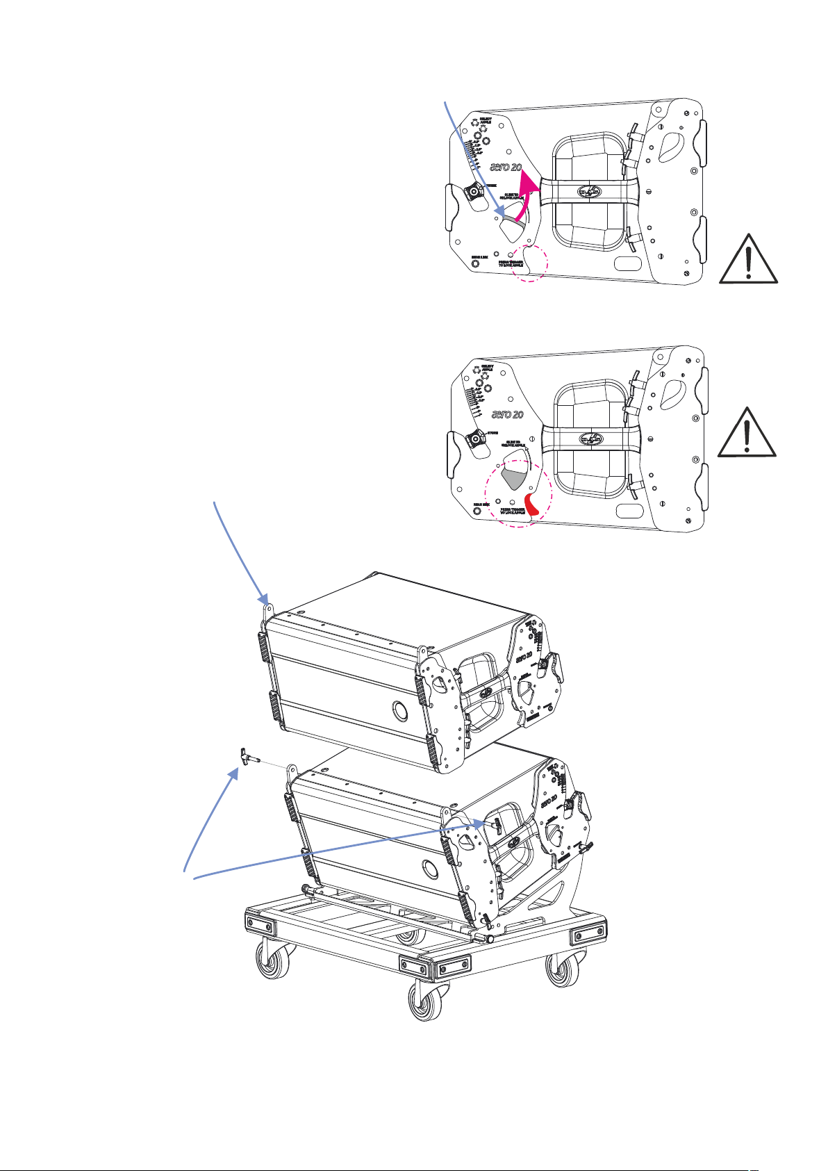
Side view of AERO-20A unit
Looking at the side of AERO-20A unit, we
observe the blocking angle trigger.
Warning: Make sure the trigger is hidden,
blocking the angle, so that the box is fixed to
the platform safely.
4
Manual de Colgado / aero series / Rigging Manual
When you push the trigger, you will block AERO-20A angles.
Page 5
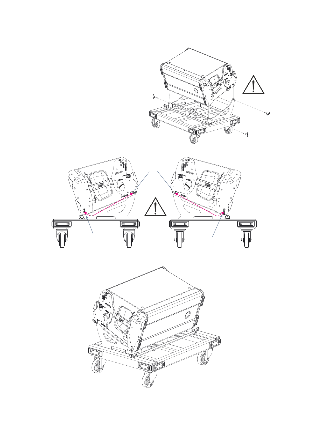
Lift the enclosure by the handles and sit it
gently over the platform.
Remove the security pins and hold the
enclosure with them.
Check that the four security pins are well
positioned.
Rear security pins:
REAR LINK
Front security pin
Front security pin
Final mounting of one enclosure on a PL-20S platform.
Manual de Colgado / aero series / Rigging Manual
5
Page 6
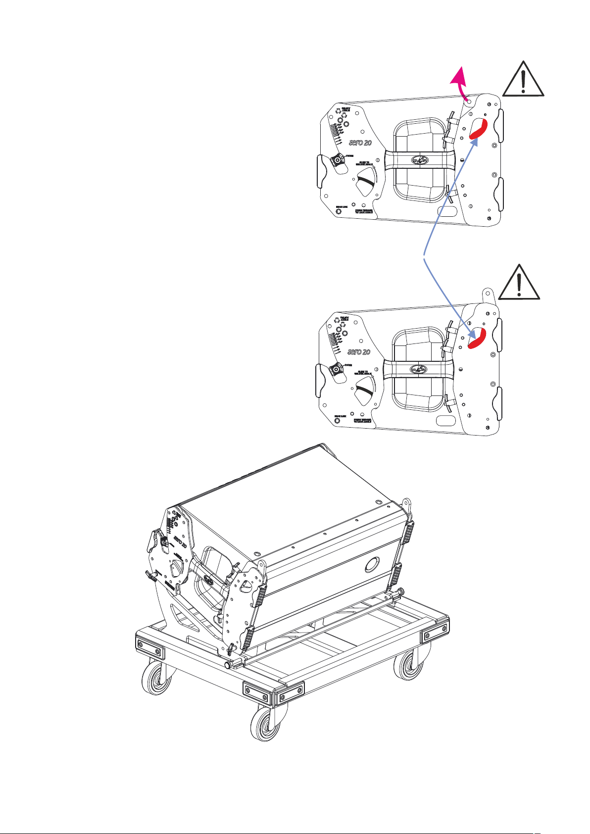
Lets add another enclosure over the previous.
We need to look at the side controls of the
enclosure and act on them like in the figure.
We push up the front rods (as seen in the
figure), we will deploy them and we will lock them
into position. Make sure they are properly locked
for safety.
The front rod remains locked, unless you press
the front triggers so that we can bring it to its initial
position, folded on the side.
The result, platform included, can be seen in
the figure below.
Move the front
folded rod
Front trigger
Click !
Front rod
unfolded
Figure of the enclosure on the platform PL-20S
with the rods ready to add another enclosure over it.
6
Manual de Colgado / aero series / Rigging Manual
Page 7
Now we unlock the angle in the second box,
before leaning it on the first (in this configuration
the rear trigger is hidden).
To do this we will move the handles on the
sides of the box up to the end where you will hear
a click.
At that time the rear trigger will come out, the
handle will lock, and it will unlock the angle.
Taking the second enclosure by the handles,
we will lower it gently upon the first enclosure, until
it rests upon it.
Remove the safety pins on each side of the
enclosure, and to anchor the enclosure we will use
these pins, as shown in the figures.
Note: We can leave the front rods
prepared for stacking the third box.
Side handle
Hidden rear trigger
Click !
Front
security
pins
Visible rear trigger
This figure shows mounting of two enclosures on a PL-20S platform.
Manual de Colgado / aero series / Rigging Manual
7
Page 8
Once the second enclosure is supported by the first and the front safety pins are positioned, we will
choose 7º (which is the maximum possible for this model), with the angle selector and we will put the rear
safety pins on the first enclosure (two on each side of the enclosures): put pins in REAR LINK holes of
second enclosure and others, in the holes corresponding to 7º angle, on the first enclosure (as shown in the
figures below).
Check that all safety pins are located correctly because they will have to withstand the weight of all the
enclosures.
Security
pins
Security
pins
DETAIL
This figure shows final mounting of two enclosures on a PL-20S platform.
8
Manual de Colgado / aero series / Rigging Manual
Page 9
Now we should unlock the angle in the third enclosure to place it on the second (in this configuration the
rear trigger is hidden, as seen on page 7).
To do this we will move the handles on the sides of the enclosure up to the end where you will hear a
click.
At that time the rear trigger will come out, the moved handle will be locked and it will unlock the angle.
Taking the third enclosure by the handles, we will lower it gently upon the second enclosure, until it rests
upon it.
Remove the safety pins on each side of the box and to anchor the enclosure we will use these pins as
shown in the figures, on page 7.
Once the third enclosure is supported by the second and the front safety pins are positioned, we will
choose also 7º with the angle selector and we will put the rear safety pins on the second enclosure (two on
each side of the enclosures): put pins in REAR LINK holes of third enclosure and others, in the holes
corresponding to 7º angle, on the second enclosure (as shown in the figures below and as seen on page 8).
Check that all safety pins are located correctly because they will have to withstand the weight of all the
enclosures.
These figures show final mounting of three
enclosures on a PL-20S platform. We can leave
the front rods prepared for stacking the fourth
enclosure, only if the group isn't finished.
Manual de Colgado / aero series / Rigging Manual
9
Page 10

Now we should unlock the angle in the fourth enclosure to place it on the third (in this configuration the
rear trigger is hidden, as seen on page 7).
To do this we will move the handles on the sides of the enclosure up to the end where you will hear a
click.
At that time the rear trigger will come out, the moved handle will be locked and it will unlock the angle.
Taking the fourth enclosure by the handles, we will lower it gently upon the third enclosure, until it rests
upon it.
Remove the safety pins on each side of the box and to anchor the enclosure we will use these pins as
shown in the figures, on page 7.
Once the fourth enclosure is supported by the third and the front safety pins are positioned, we will
choose also 7º with the angle selector and we will put the rear safety pins on the second enclosure (two on
each side of the enclosures): put pins in REAR LINK holes of fourth enclosure and others, in the holes
corresponding to 7º angle, on the third enclosure (as shown in the figures below and as seen on page 8).
Check that all safety pins are located correctly because they will have to withstand the weight of all the
enclosures.
These figures show final mounting of four
enclosures on a PL-20S platform.
Do not stack more than four boxes so as
not to endanger stability.
10
Manual de Colgado / aero series / Rigging Manual
Page 11
ARRAY MOUNTING WITH GROUPS OF 4 UNITS ON A PL-20S
The groups of 3 or 4 units are easy to
transport by truck.
Lets see in this section how to mount an array
with groups of four units.
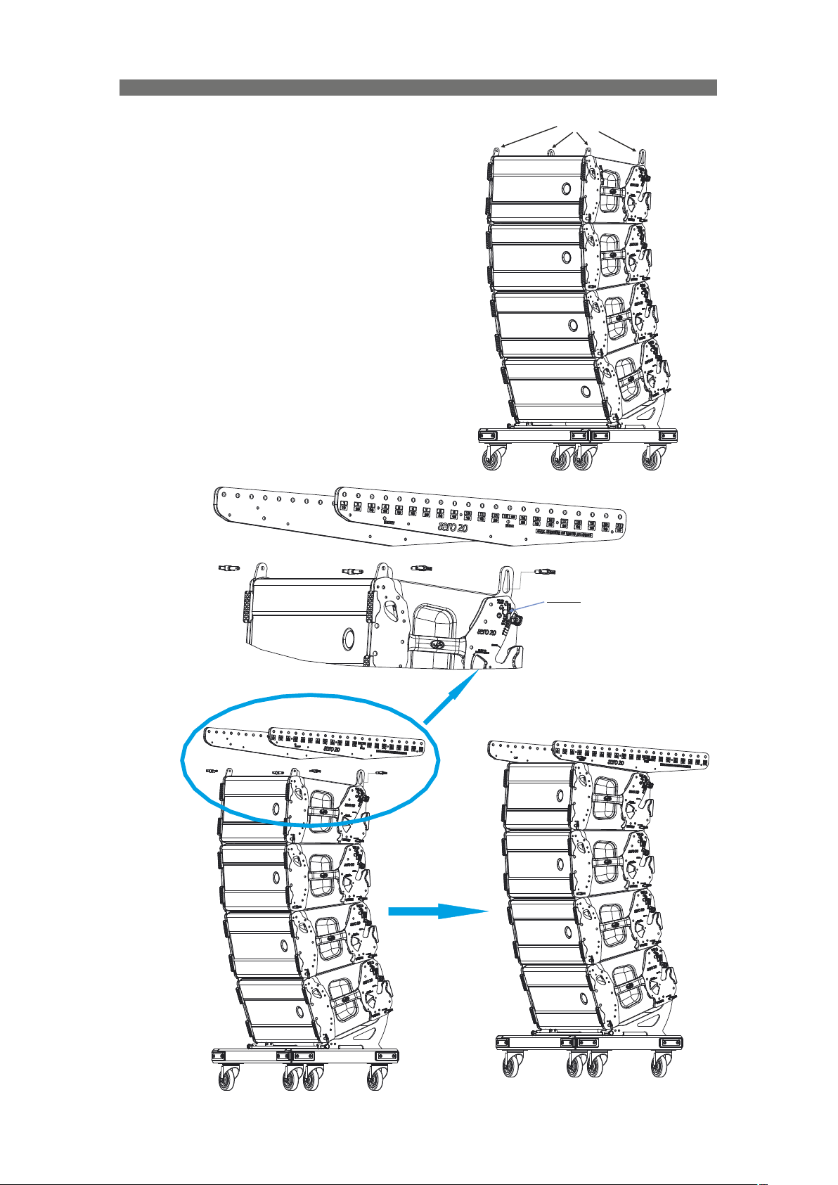
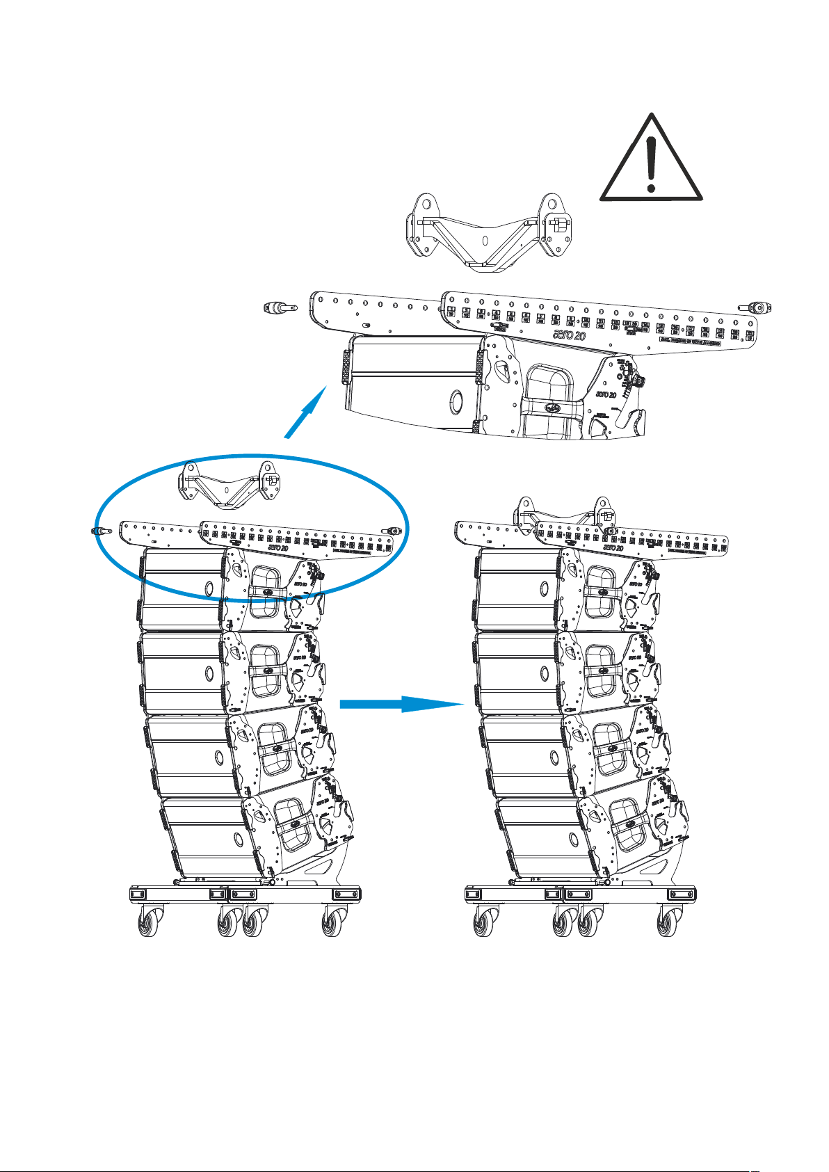
Firstly, we will mount the AX-AE20 onto the top
enclosure of the first group of four units.
Therefore, to mount the AX, the rods of the
upper unit of the group should be extracted, as
explained in the previous section.
The result is shown in the figure at the right.
Then, place the side parts of the AX inserting
safety pins, as shown in the figure below.
Check that the security pins are well positioned
because they will support the weight of the rest of
the enclosures.
Rods
DETAIL
Note:
Select 0º angle and the
safety pin should put it
to lock the rear rod
RESULT
Manual de Colgado / aero series / Rigging Manual
11
Page 12
With the help of the Ease Focus software we can
determinate which point is the correct one to join
the side pieces with the crossbar of the AX-AE20,
called PICKUP-AX-AE20, and with the help of the
security pins, as shown in figures.
If we use two lift motors, we will use a second
PICKUP-AX-AE20 which joins through the same way
to the pinpoint marked by Ease Focus software.
Check that the security pins are well
positioned.
DETAIL
AX-AE20
W.L.L.: 715 kg
PICKUP-AX-AE20
W.L.L.: 715 kg
RESULT
Lastly, hook the lift motor. In case two lift motors are needed, hook each one to each PICKUP-AX-AE20.
Like in every security operation, use adecuate security elements.
12
Manual de Colgado / aero series / Rigging Manual
Page 13

Proceed to assign the angles to each enclosure.
Note that the angle for the first enclosure is 0º (the security pin is positioned in the SELECT ANGLE hole
for this angle). This is the right position for it.
With the help of the Ease Focus software we will know the correct angle to each enclosure. This process is
similar for all the enclosures.
But first, pay attention to the silkscreen on the enclosure's side.
SELECT ANGLE
holes for
security pins
Example of blue
discontinuous line
Example of white
continuous line
Angle selector handle
We can see that there are two types of lines (continuous and discontinuous), with two colors (white and
blue).
Thus, each selectable angle is matched with a hole to fix a security pin, ie, a hole presents the same type
of line and color that the angle chosen with the angle selector handle.
Therefore, if we choose an angle, we will place a security pin in the hole with the same type of line and
color (see example below).
Example: SELECT ANGLE = 7º
Manual de Colgado / aero series / Rigging Manual
13
Page 14

Now, we shall proceed to assign the angles between each
pair of enclosures.
Remember that the angle for the first enclosure is 0º (the
security pin is positioned in the SELECT ANGLE hole for this
angle). This is the right position for it.
Also remember that you have to do the same in the reciprocal
sides of the same boxes (in the figures only one side is
illustrated).
1.- Take out the
security pin from
the SELECT
ANGLE hole of the
lower enclosure.
2.- Select the desired
angle, for example 1º.
DETAIL
DETAIL
14
DETAIL
4.- Push the rear
trigger to lock the
angle in each side of
the enclosure.
3 .- R epl ace t he
security pin in the
appropriate "SELECT
ANGLE" hole. In the
example, into 1º (this
hole is the same as
for 7º, 5º, 3º and 1º).
Manual de Colgado / aero series / Rigging Manual
DETAIL
Page 15

Once that we have assigned the angle between the first pair of enclosures, acting on both sides of
enclosures, we shall repeat the same process to select the angle between the second and third. And so on
until the last.
We shall reallocate the angles of the example so that they may be more usual angles, we are going to
think of an array consisting of 8 enclosures.
Note: The selected angles will be visible when we lift the enclosures, so before lifting the group you can
easily assign, and change, angles.
In this new case, we shall assign:
Between first and second: 0.5 °
Between second and third: 1
Between third and fourth: 1.5 °
Note that the angle is obtained by acting on the lower enclosure, so that we may have determined angle
between the fourth and fifth enclosures, you should act on the fifth when you have added it.
At this point, so that we may add more enclosures we should disengage the platform.
1º
DETAIL
2º
LIFT
1º
1º
As shown in the figures: First we will remove
the security pins of the platform (4 units) and then
we shall lift the group of enclosures.
When lifting, we see that the group separates
from the platform, and we shall hear a few clicks
when selected angles will be blocked between the
enclosures.
Manual de Colgado / aero series / Rigging Manual
15
Page 16

This figure shows the result when we lift the
group.
0º
0,5º
1º
1,5º
16
Manual de Colgado / aero series / Rigging Manual
Page 17

Box No.1
Box No.2
Now, we shall proceed to assign the angles in the next
group of 4 units, as before, with the same procedure we shall
assign:
Between fourth and fifth: 2º
Between the fifth and sixth: 4º
Between the sixth and seventh: 6º
Between the seventh and eighth: 7º
As we have done before and according to the following
figures.
1.- First, we will draw the
rods from the upper unit (box
No.5) of the new group of boxes
1.
(as on page 11). Then we shall
assign the angle between the
upper enclosure of the next
group and the lower enclosure
of the previous group. For this,
we will insert the security pins in
the SELECT ANGLE holes
corresponding to 2º.
Box No.3
Box No.4
Box No.5
Box No.6
Box No.7
DETAILS
2.
3.
2.- We shall let down
the previous group until
the front rods of the
upper box of the new
group (box No.5) are
aligned with the holes of
the lower enclosure of
the previous group (box
No.4). Then we shall put
the security pins to link
the front.
3.- We shall continue
lowering the upper group
until fully supported by the
lower group. Finally, we
will put the security pins in
REAR LINK holes of box
No.4, joining all boxes.
Box No.8
Manual de Colgado / aero series / Rigging Manual
17
Page 18

Once the upper enclosure of the new group is
joined, we will assign the angles of the other
enclosures, following the instructions of the Ease
Focus software.
In this example:
Between fourth and fifth: 2º
Between fifth and sixth: 4º
Between sixth and seventh: 6º
Between seventh and eighth: 7º
The procedure for assigning angles to the
boxes is the same as described with the first
group of 4 units.
As already mentioned, after assigning the
angle you need, you will have to press the
rear trigger to lock it.
The same applies to the process for removing
the platform.
1º
DETAIL
2º
LIFT
1º
1º
18
Manual de Colgado / aero series / Rigging Manual
Page 19

Here, the figures show final mounting for this example of a typical array with 8 units.
0º
0.5º
1º
1.5º
2º
4º
6º
7º
Manual de Colgado / aero series / Rigging Manual
19
Page 20

ARRAY DISASSEMBLY IN GROUPS OF 4 UNITS ON A PL-20S
The groups of 4 units are easy to transport by truck as we shall see below. This section describes how to
disassemble an array in groups of 4 units.
First, we go down aligning the array with the platform PL-20S, as shown in the figures below.
20
Manual de Colgado / aero series / Rigging Manual
Page 21

Before supporting the array on the platform, it is important to unlock the angles of the
corresponding boxes (see figure boxes No.2, No.3 and No.4, leaving the No.1 blocked), just as seen on
page 7, so that the angles can fold, when we go down with the enclosures, onto the platform.
Box No.4
Box No.3
Box No.2
Box No.1
Manual de Colgado / aero series / Rigging Manual
Box No.4
Box No.3
Box No.2
Box No.1
21
Page 22

Now, we shall give the two lateral pins of the platform a half turn
as shown in the below figure (1).
This will allow us to release the tray of the platform (2) and raise it.
Align the front holes of the tray and the enclosure, and link them
with two security pins (3).
DETAIL
3
3
2
1
These lateral pins
release the tray
from the platform
Then we will go down the array until it rests on
the platform (4). Be very careful with this
operation to avoid accidents. Use personal
safety elements required as safety shoes,
gloves, etc.
We will turn the lateral pins of the platform so
that the tray is blocked and, finally, place the
security pins in the REAR LINK holes (5).
1
4
22
5
Manual de Colgado / aero series / Rigging Manual
Page 23

Now, we will continue going down the array,
resting it on the platform. When the four lower
boxes are resting, we shall proceed to remove the
security pins, as shown in the following figures.
1.- We shall remove the
security pins of the REAR
LINK holes of the upper box.
1.
2.- Then we shall remove
the front security pins.
2.
DETAILS
3.
3.- We shall lift the rest of
the array a little and we shall
draw this group of boxes
from under the top group,
then we shall fold the front
rods acting on the front
trigger, we will remove the
security pins of SELECT
ANGLE holes and we will
move the handles to STORE
position (folding the rear
rods).
To d i s a s s e m b l e t h e
remaining enclosures, we shall
proceed as with the first group.
Manual de Colgado / aero series / Rigging Manual
23
Page 24

COMBINATION WITH AERO-40A ARRAY
The AERO-20A and AERO-40A units can be combined to form an array. This type of mixed array requires
an accessory, the AX-COMBO2040. In this section we will learn how to use it.
AX-COMBO2040
WLL: 300 kg
Place two pins
on each side
The AX-COMBO2040 should be mounted on the
aero20A group as shown in the figures.
Check that all security pins are located correctly
because they will withstand the weight of all the AERO-20A
enclosures.
In our website you will find an explanatory guide to the
different types of DAS Audio Group, S.L. security pins,
and where they are used, with explanatory drawings.
The result can be seen in the figure below.
The pins to link with AERO-40A
are included in AX-COMBO2040.
Place the pin in
SELECT ANGLE hole
that we have obtained
in the Ease Focus
software, for our
application.
24
Manual de Colgado / aero series / Rigging Manual
Page 25

As shown in the following figures, AERO-20A and AERO-40A enclosures joined by the AX-COMBO2040
PIN
Ø (mm)
L (mm)
Ref.
PIN-6-C
6
15
30003600
PIN-6623
30002878
PIN-8-C
8
22
30006080
PIN-8830
30002877
accessory.
Check that all security pins are located correctly because they will have to withstand the weight of all the
enclosures. They are of different sizes and are placed in both sides of the accessory.
PIN-8
PIN-8-C
PIN-8-C
In our website you will find an explanatory guide to the different types of security pins provided by DAS
Audio Group, S.L., and where they are used, with explanatory drawings. Here, is a chart with the different
sizes.
Ø
L
PIN-8
Manual de Colgado / aero series / Rigging Manual
25
Page 26

The result, when we lower the array of AERO40A onto an AERO-20A group and join them, we
will have:
The result is shown in the figure at the right.
It will suffice with that we lift the array, remove
the platform and secure the array to the correct
height, to complete the assembly of this
combination of boxes.
To disassemble, we must continue with the
same sequence of steps, but in reverse order.
Note: Save the PIN 8 type in the interior holes
of AX-COMBO2040, to prevent loss.
26
Manual de Colgado / aero series / Rigging Manual
Page 27

STACKING SYSTEMS
The PL-20S platform can help transport the units, but if used to stack systems, the array could be
unstable, because the array’s angles can move the center of gravity. This is the reason why we don't
recommend its use to stack systems.
However, the PL-218CS doesn’t have this problem, so it is possible to use it for stacking systems and to
transport them (maximum of 3 units of any version of LX-218CA).
Therefore, we will have the following accessories for stacking systems of aero series:
The PL-218CS is a platform that allows the
transportation and stacking use, up to 3 stacked
units of LX-218CA (all versions).
These holes allow to
screw the AXS platforms to
the subwoofer cabinets
PL-218CS
WLL: 400 kg
AXS-AE20
WLL: 150 kg
The AXS-AE20 is a platform that allow the stacking of AERO-20A units (up to a maximum of 4 units), over
subwoofer enclosures.
Warning: The platform and the subwoofer enclosures should be joined, with screws or with
endless ratchet straps (not included), for a safe stacking (see the examples below).
With endless
ratchet straps
Manual de Colgado / aero series / Rigging Manual
With screws
27
Page 28

The AXS-AE20 accessory allows assigning angles to the enclosures easily, following the instructions (see
the figures below).
0º
The AXS-AE20 accessory in combination with the AXC-ZT accessory allows for system applications
as shown in the lower figures.
Warning: Don’t stack more units than recommended:
MAX STACKED UNITS:
Ÿ 4 UNITS on AXS-AE20
Ÿ
Ÿ 1 UNIT on AXS-AE20 with AXC-ZT
+3.5º -3.5º
28
Manual de Colgado / aero series / Rigging Manual
Page 29

TRANSPORTING
This section describes aero unit transport recommendations
We will start with two examples of configurations and we will recommend different ways of loading them
inside a truck.
eCP_20
eCP_20
2
1
3
eCP_20
3
PUSH
2
1
2
3
1
2
3
1
2
3
1
2
3
1
2
3
1
2
3
1
2
1
3
3
PUSH
2
1
2
1
3
3
PUSH
2
1
L2
L1
2
3
1
2
3
1
2
3
1
2
3
1
2
3
1
2
3
1
L3
I
o
FI4030mA4pol.
FI-Schalter
6xMCB 16A “C” 1pol.
1xRCD 40A 30mA 4pol.
DASNET-RACK-26
eCP_20
eCP_20
Example 1: 16 x AERO-20A + 8 LX-218CA-NET
L R
LINK L
LINK R
1
3
PUSH
2
2
1
2
1
2
1
2
1
2
1
2
1
1
3
PUSH
2
1
3
PUSH
2
2
3
1
3
3
3
3
3
3
2
3
1
2
3
1
eCP_20
L2
L1
2
3
1
2
3
1
2
3
1
2
3
1
2
3
1
2
3
1
L3
I
o
FI4030mA4pol.
FI-Schalter
6xMCB 16A “C” 1pol.
1xRCD 40A 30mA 4pol.
DASNET-RACK-26
eCP_20
IN OUT1 OUT2 OUT3 IN OUT1 OUT2 OUT3
eCP_3 eCP_3
eCP_3 eCP_3
eCP_20
IN OUT1 OUT2 OUT3 IN OUT1 OUT2 OUT3
Manual de Colgado / aero series / Rigging Manual
eCP_3 eCP_3
eCP_3 eCP_3
29
Page 30

x 4
IN OUT1 OUT2 OUT3
DASnet Splitters
4 x aero20
4 x aero20
Steel case intended for distribution of analog audio,
monitoring data and power to multiple devices.
It includes: - one input power (1 x powerCon true 1) and 3
power outputs (3 x powercon NAC3MPB).
One audio+monitoring data input,
and three audio + monitoring data ouputs
243cm / 96”
4 x aero20
4 x aero20
4 x aero20
4 x aero20
228cm / 90”
4 x aero204 x aero20
4 x aero20
4 x aero20
251cm / 99”
4 x aero20
4 x aero20
x 4
16 AERO-20A
x 1
DSP-2060A
Processors (included in the racks)
PL-20S metal transport dolly for 3/4 AER O-20A
16 AERO-20A + 8 LX-218CA-NET
x 8
Euro truck 6m Trailer
4 x aero20
4 x aero20
4 x aero20
4 x aero20
2 x LX218CA
2 x LX218CA
2 x LX218CA
2 x LX218CA
2 x LX218CA 2 x LX218CA 2 x LX218CA 2 x LX218CA
American Truck 90” x 232”
x 4
x 4
4 x aero20
4 x aero20
228cm / 90” 243cm / 96”
4 x aero20
4 x aero20
American Truck 99” x 232”
4 x aero20 4 x aero20
251cm / 99”
2 x LX218CA
2 x LX218CA
2 x LX218CA
2 x LX218CA
4 x aero20 4 x aero20
x 4
Accessories
Speaker cabling Dollies
30
x 8
x 12
x 12
Plink1_09 (power link 2,5mm2 90cm)
eCP_20 (C AT 7 ethernet cable + 3x2,5mm2, audio +data + power, 20m lenght)
eCP_3 (C AT 7 ethernet cable + 3x2,5mm2, 3m lenght)
eC_09 (CAT 7 ethernet cable; audio +data, 90cm lenght)
DASnet-Rack 26 (1 DASnet patch 26 + power distro 32Amp)
Manual de Colgado / aero series / Rigging Manual
x 2
2
1
3
3
PUSH
2
1
2
3
1
2
3
2
1
3
1
2
3
1
2
2
3
3
1
1
2
3
1
2
3
2
1
3
1
2
3
1
2
3
1
2
1
3
3
PUSH
2
2
1
3
1
2
1
3
3
PUSH
2
1
L2
L1
L3
I
o
FI4030mA4pol.
FI-Schalter
6x MC B 16A“C” 1pol.
1x RC D 40A30mA 4pol.
FUN-2-L X218C nylon cover for a stack of 3 LX-218CA-N ET
Rigging frames
Covers
FUN-4-A E20 is a protective nylon cover for 4 AERO-20A
x 2
AX-AE20
Dollies
PL-218CS
The PL-218C S dolly is used to transport
stacks of 2 or 3 LX-218C A-NET.
Page 31

Here is the second example:
eCP_20
eCP_3
eCP_3
eCP_3
eCP_20
eCP_20
eCP_20
IN OUT1 OUT2 OUT3
2
1
3
3
PUSH
2
1
2
3
1
2
3
1
2
3
1
2
3
1
2
3
1
2
3
1
2
1
3
3
PUSH
2
1
2
1
3
3
PUSH
2
1
L2
L1
L3
2
3
1
I
o
2
3
1
FI4030mA4pol.
FI-Schalter
2
3
1
2
6xMCB 16A“C” 1pol.
3
1
2
3
1
2
3
1
eCP_20
1xRCD 40A30mA 4pol.
eCP_3
eCP_3
DASN ET-RACK-26
IN OUT1 OUT2 OUT3
eCP_3
Example 2: 24 x AERO-20A + 12 LX-218CA-NET
2
1
3
3
PUSH
2
1
2
3
1
L R
2
3
1
2
3
1
2
3
1
2
3
1
2
3
1
2
1
3
3
PUSH
2
1
2
1
3
3
PUSH
2
1
L2
L1
L3
2
3
1
I
o
2
3
1
FI4030mA4pol.
FI-Schalter
2
3
1
2
6xMCB 16A“C” 1pol.
1xRCD 40A30mA 4pol.
3
1
2
3
1
2
3
1
DASN ET-RACK-26
eCP_20
eCP_20
IN OUT1 OUT2 OUT3
eCP_3
eCP_3
eCP_3
eCP_20
eCP_20
eCP_20
IN OUT1 OUT2 OUT3
Manual de Colgado / aero series / Rigging Manual
eCP_3
eCP_3
eCP_3
31
Page 32

x 4
IN OUT1 OUT2 OUT3
DASnet Splitters
4 x aero20
4 x aero20
4 x aero20 4 x aero20
Steel case intended for distribution of analog audio,
monitoring data and power to multiple devices.
It includes: - one input power (1 x powerCon true 1) and 3
power outputs (3 x powercon NAC3MPB).
One audio+monitoring data input,
and three audio + monitoring data ouputs
243cm / 96”
4 x aero20 4 x aero20
4 x aero20
4 x aero20
228cm / 90”
4 x aero20
4 x aero20
4 x aero20
4 x aero20
4 x aero20
4 x aero20
251cm / 99”
4 x aero20 4 x aero20
4 x aero20 4 x aero20
x 6
24 AERO-20A
x 2
DSP-2060A
Processors (included in the racks)
PL-20S metal transport dolly for 3/4 AER O-20A
24 AERO-20A + 12 LX-218CA-NET
x 12
3 x LX218CA 3 x LX218CA 3 x LX218CA 3 x LX218CA
Euro truck 6m Trailer
4 x aero20 4 x aero20
4 x aero20 4 x aero20
4 x aero20 4 x aero20
228cm / 90” 243cm / 96”
4 x aero20
4 x aero20
4 x aero20
4 x aero20
4 x aero20
4 x aero20
3 x LX218CA 3 x LX218CA 3 x LX218CA 3 x LX218CA
American Truck 90” x 232”
x 6
x 4
251cm / 99”
3 x LX218CA
3 x LX218CA
3x LX218CA
3 x LX218CA
4 x aero20 4 x aero20 4 x aero20
4 x aero20 4 x aero20 4 x aero20
American Truck 99” x 232”
x 4
Accessories
Speaker cabling Dollies
32
x 10
x 18
x 18
Plink1_09 (power link 2,5mm2 90cm)
eCP_20 (C AT 7 ethernet cable + 3x2,5mm2, audio +data + power, 20m lenght)
eCP_3 (C AT 7 ethernet cable + 3x2,5mm2, 3m lenght)
eC_09 (CAT 7 ethernet cable; audio +data, 90cm lenght)
DASnet-Rack 26 (1 DASnet patch 26 + power distro 32Amp)
Manual de Colgado / aero series / Rigging Manual
x 2
2
1
3
3
PUSH
2
1
2
3
1
2
3
2
1
3
1
2
3
1
2
2
3
3
1
1
2
3
1
2
3
2
1
3
1
2
3
1
2
3
1
2
1
3
3
PUSH
2
2
1
3
1
2
1
3
3
PUSH
2
1
L2
L1
L3
I
o
FI4030mA4pol.
FI-Schalter
6x MC B 16A“C” 1pol.
1x RC D 40A30mA 4pol.
FUN-3-L X218C nylon cover for a stack of 3 LX-218CA-N ET
Rigging frames
Covers
FUN-4-A E20 is a protective nylon cover for 4 AERO-20A
x 2
AX-AE20
Dollies
PL-218CS
The PL-218C S dolly is used to transport
stacks of 2 or 3 LX-218C A-NET.
Page 33

ANNEX I : Tools for rigging systems
For best results when hanging aero series 2 systems, it is mandatory the use of Ease Focus 2 simulation
software which can be downloaded for free from the support section of our website . www.dasaudio.com
The download file contains the software and data files with gll files for acoustic systems.
The user should be aware that any deviation in the actual installation of the system with respect to
the simulated data can affect the system’s coverage, especially in the long throw. Therefore DAS can
provide clinometers and laser meters to accurately perform the installation of the system:
Leica Disto D5 Laser Meter
Clinometer which is attached to the top
cabinet of the array and sensor module.
TEQSAS LAP-TEQ
Manual de Colgado / aero series / Rigging Manual
33
Page 34

ANNEX II : Maximum load capacity for AX-AE20
AX-AE20
AX-AE20 modular flybar set is comprised of two side panels of steel and aluminum and a
central crossbar (PICKUP-AX-AE20).
The maximum load capacity is 20 units * (pick-up point dependent) with a 5:1 safety factor.
For systems of 12 units or more, an additional bar should be added and the array will hang
from two lift motors for greater security and control over the angle of the system at all times.
AERO-20A load limitation: * On the side panels the maximum number of units that can be flown
are screen printed depending on the pick-up point marked by the software (or vertical axis of the
center of gravity of the system). Consulting the EASE Focus 2 software we will determine the number
of units which can be flown from each pick-up point.
pick-up point
maximum
number of units
These limitations depend on the load of the vertical axis position of the center of
gravity of the system:
From points 2 to 20 regardless of whether you use a motor or two, a maximum of
20 AERO-20A units can be flown.
At point 1, 19 units of AERO-20A can be flown.
At point 21, 19 units of AERO-20A can be flown.
Pick-up point - vertical axis of the center of gravity
In the image at the right you can see the vertical axis of the center
of gravity for the system passing through the pick-up point number
11.
pick-up
point
The pick-up point shown in the software is placed in alignment
with the vertical axis of the center of gravity for the system. The
position of this vertical axis obviously depends on the number of
boxes, the angle between them and full vertical angle. The loading
limitations are displayed by the software and depend on the vertical
axis that position the center of gravity.
34
Manual de Colgado / aero series / Rigging Manual
Page 35

For example, lets take a system of 16 AERO- 20A units. If we consult the
panel lettering of the AX-AE20, we observe that 16 units can be flown when
the vertical axis of the center of gravity is aligned with any of the 21 hanging
positions.
In the simulation attached, the system is flown at 10 meters with -6.98º of
inclination. No warning of maximum load appears.
The warnings of maximum load appear ONLY if the number of cabinets is
greater than 19 units. For more than 19 units, the warnings of load appear and
we should check where the vertical axis of the center of gravity for the system
is situated.
See what happens if we add four more boxes.
Now we have a total of 20 AERO-20A units and the
software warns us that only 20 units from point 2 at
20 can be flown.
In this case, we have -6.98° of inclination, the
vertical axis of the center of gravity of the system is
positioned in alignment with the pick-up point
number 20. In this case, we are within the safety
margins. Remember that from point 2 to point 20,
20 units can be flown (see above panel drawing AX-
AE20).
20 AERO-20A units - As the axis of the vertical center of gravity coincides
with the point 20, we can fly 20 units with that configuration.
Manual de Colgado / aero series / Rigging Manual
35
Page 36

ANNEX III : Advice for EASE Focus 2 use
It’s important to understand the signs of the system's total angles in the EASE Focus
2 software program.
A cluster can be flown at different angles, depending on the number of cabinets, the
angle between them and the pick-up point. The angle in the software is defined in
section View [º]
Inclining systems forwards (downwards) result in a negative angle ( ). The systems -
inclined upwards result in a positive angle ( ).+
+
Angle criteria of the cluster
-
-5º
6 AERO-20A at -5º
6 AERO-20A at +10º
+10º
36
Manual de Colgado / aero series / Rigging Manual
Page 37

Meaning of parameter DELTA EASE Focus 2:
The delta parameter marks the angle NEEDED to reach the desired angle in our system
(View [°]). This information is useful ONLY when the system is flown from a single POINT.
Imagine a system of 8 units hanging 11 meters high.
The desired angle is: View [°] -15°
As shown in the image, Delta [º] -0.69º
This means that to reach the desired -15 º, we are
lacking 0.69º when the system is flown at the point 19.
If the delta sign is negative (-), this indicates that we are
lacking 0.69 downwards.
If the delta sign is positive (+), this means that we are
lacking degrees upwards.
+
Angular criteria of delta
-
Now, we consider the opposite case.
This is the same system hanging from a single point. 8
AERO-20A units.
The desired angle: View [°] -12°
In this case Delta [º] is 0.53º
This means that if we hang the system from point 18 we
lack tilt up 0.53º to reach the desired -12º.
Manual de Colgado / aero series / Rigging Manual
37
Page 38

DELTA parameter in EASE Focus 2 software and maximum angles:
As seen before the DELTA parameter makes a difference (in excess or in lack of) between the desired angle and
the obtained angle to hang the system from a single point.
When we fly the system from TWO points, this parameter is very useful because we also determine the maximum
angles with which we can install it.
For example, suppose a set of 16 AERO-20A units:
The system is inclined -7,27º
Vertical axis position of center of gravity is aligned with
the pick-up point number 19.
To what maximum angle could we tilt down the
system?
Suppose we want to hang the system at -15°.
Let's see what happens in the software:
Observe how Delta: -8.37º
This means that we lack to reach the
desired 8.37º, -17º.
In this case the system could only have a
maximum tilt: 17-8.37 = 8.63°
since no further pick-up points are available
on the AX-AE20.
38
Indeed if we change the angle of the system to -8.63°, we see that the
pick-up point (vertical axis of center of gravity) is number 21 and delta
is zero.
Manual de Colgado / aero series / Rigging Manual
Page 39

www.dasaudio.com
RM_AE20_02_EN
DAS Audio Group, S.L.
C/. Islas Baleares, 24
46988 Fuente del Jarro
Valencia, SPAIN
Tel. +34 96 134 0860
DAS Audio of America, INC.
6900 NW 52th Street
Miami, FL. 33166 - U.S.A.
TOLL FREE: 1 888 DAS 4 USA
DAS Audio Asia PTE. LTD.
3 Temasek Avenue, Centennial
Tower #34-36
Singapore 039190
Tel. +65 6549 7760
DAS do Brasil LTDA.
Rua Dos Andradas, 382 SL
Santa Efigênia, São Paulo
Brasil. CEP: 01208-000
Tel. +551133330764
 Loading...