

Page 1

speaker management software
www.dasaudio.com
UM_DASnet1.15_EN
Page 2

INDEX
DASnet HARDWARE
DASnet HARDWARE 4
BASIC CONNECTIONS
DASnet SOFTWARE
INTRODUCTION
INSTALLING THE SOFTWARE
STARTING THE SOFTWARE
LAYOUT OF THE MAIN WINDOW
REORGANISING THE WINDOW
AUTO-HIDING WINDOWS
ZONING DEVICES
COMMUNICATION WITH THE DEVICES
AUTO-SCAN
DASnet dnd FILES
ADDING DEVICES MANUALLY
DEVICE VIEW WINDOWS
ROAD SERIES
CONVERT 15A
AERO 40A
LX-218CA_net
aero 20A
DEVICE VIEW WINDOWS - DSP
MIXER MENU
INPUT EQ MENU
OUTPUT EQ MENU
LINK MANAGER
CUSTOM PANELS
IMAGE LIBRARY MANAGER
APPENDIX 1. QUICK AERO40A SYSTEM CONFIGURATION
APPENDIX 2. MOVE TO MAIN WINDOW
APPENDIX 3. SNAPSHOTS
9
12
12
13
14
15
17
18
19
19
21
23
24
24
27
31
35
38
42
42
45
45
47
53
60
61
66
68
DASnet - 2
Page 3

hardware
DASnet - 3
Page 4
1. DASnet HARDWARE
DASnet is a remote monitoring and control software designed to be used with self powered DAS
Audio systems and digital signal processors.
Besides monitoring the “status” of the amplifier channels and speaker´s impedance (loads) the user
may configure different settings on the systems (presets).
The software it is based on an RS-485 network. All devices on the net have to be connected in a
daisy chain / star configuration.
D.A.S. Audio devices equipped with DASnet are:
Road series, LX-218CA_net, Convert 15A, aero 40A, aero 20A.
The hardware needed to use DASnet will be provided by DAS Audio. The use of any other
materials not supplied by the manufacturer will not assure the optimal performace of the system
and may cause interference problems between analog audio and monitoring data.
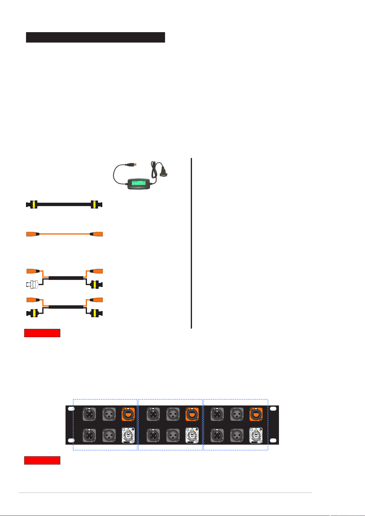
DAS Audio strongly recommends the use of these accessories:
USB-RS485 converter D.A.S. Audio code
USB-RS845
Power Link:
Plink1_09
(number refers to cable length, meters)
EtherCon cable (eC):
Shielded STP CAT7 cable
eC_0.9, eC_2, eC_20
(number refers to cable length, meters)
EtherCon cable + Powercable (eCP):
Shielded CAT7 cable
Power cable 3x2.5mm2
aero 40A, Convert 15A
Shielded CAT7 cable
Power cable 3x2.5mm2
Road 12A_net,
eCP_20, eCP_3
(number refers to cable length, meters)
eCPk_1 / eCPk_5 /
(number refers to cable length, meters)
Road 15A_net
Important
Only use DAS Audio cables with DASnet. Any other type of cabling may cause
interferences and background noise.
DASnet patch panel:
DASnet patch
Audio / power and DASnet patch panel to connect all the devices on the net
Three independent audio / dasnet / power “zones”
DASnet DASnet DASnet
OUT OUT OUTOUT OUT OUT
IN IN IN
IN IN IN
1 2 3
Audio Audio Audio
IN IN IN
OUT OUT OUT
Important
audio and DASnet data can be linked between “zones”
On the DASnet patch panels the ethercon connectors (orange) are used to transport
ANALOG audio and DASnet DATA.
DASnet - 4
Page 5
230V DASnet Rack:
230V DASnet Rack
Includes two or more DASnet patch panels and one 32Amp 3phase power distro.
Each phase is connected to two powercon outputs.
The patch panel has different “zones”
DASnet DASnet DASnet
IN IN IN
Audio Audio Audio
IN IN IN
DASnet DASnet DASnet
IN IN IN
Audio Audio Audio
IN IN IN
IN IN IN
OUT OUT OUTOUT OUT OUT
1 2 3
OUT OUT OUT
IN IN IN
OUT OUT OUTOUT OUT OUT
1 2 3
OUT OUT OUT
EDIT
limited by the maximum current allowed
by the powerCon conector (20A).
On each “zone” there is an audio input
and a DASnet input. Also there are two
outputs per zone, audio and DASnet
data.
The main out to the cabinets is
composed by a powercon and an
Ethercon Out that is used to send
ANALOG audio and monitoring / control
DATA.
115V DASnet Rack:
6 x MCB 16A “C” 1pol.
1 x RCD 40A 30mA 4pol.
FI-Schalter
FI4030mA 4pol.
I
o
L1
L2
L3
115V DASnet Rack
Includes two or more DASnet patch panels and two 30Amp 3 phase powe distrospower distros.
The patch panel has different “zones”
limited by the maximum current allowed
by the powerCon conector (20A).
On each “zone” there is an audio input
and a DASnet input. Also there are two
outputs per zone, audio and DASnet
data.
DASnet DASnet DASnet
IN IN IN
Audio Audio Audio
IN IN IN
DASnet DASnet DASnet
IN IN IN
Audio Audio Audio
IN IN IN
IN IN IN
OUT OUT OUTOUT OUT OUT
1 2 3
OUT OUT OUT
IN IN IN
OUT OUT OUTOUT OUT OUT
1 2 3
OUT OUT OUT
EDIT
The main out to the cabinets is
composed by a powercon and an
Ethercon Out that is used to send
ANALOG audio and monitoring / control
DATA.
Important
Each “zone” can have different analog audio inputs.
Never connect an ethernet device (router, switch etc) to the DASnet patch pannels.
DASnet uses STP CAT7 ethercon cables to transport analog audio and data. It is not a
real ethernet NET.
DASnet - 5
Page 6
DASnet patch 26 and 48: (NEW)
There are two new models of the DASnet patches, totally compatible with the existing
DASnet cabling. These patches are intedended to save cabling and to be used always in
conjunction with DAS dsp´s.
The patch pannel has two/four inputs directly connected to the input channels of the
processor. Two or four audio links (signal in parallel before processing) are also available. In the
output section (depending on the processor model) 6 or 8 audio outputs (processed) are available.
Linked to each output there is an ethercon output carrying DASnet and analog audio (processed
audio from the dsp´s channel).
DASnet patch48
input section
PUSH
PUSH
PUSH
231
231
231
2
1
3
2
1
1
3
audio links (thru)
PUSH
231
2
2
1
3
3
2
1
3
processed analog audio + DASnet data
DASnet patch26
input section
PUSH
231
1
PUSH
231
2
2
1
3
3
audio links (thru)
230V DASnet Rack26 and 48: (NEW)
processed analog outputs
2
2
2
1
1
3
1
3
3
2
1
1
3
3
2
2
1
1
3
3
processed analog outputs
2
2
2
1
1
3
1
3
3
2
1
1
3
3
2
2
1
3
processed analog audio + DASnet data
PUSH
231
2
2
1
3
DASnet IN/OUT
PUSH
231
2
1
3
DASnet IN/OUT
Includes one DASnet patch26 (48) panel and one 32Amp 3phase power distro.
Each phase is connected to two powercon outputs.
EDIT
PUSH
PUSH
PUSH
231
231
2
2
1
1
3
3
PUSH
231
231
2
2
2
2
2
1
1
1
3
3
2
2
1
1
3
3
1
3
3
2
1
3
1
1
3
3
PUSH
231
2
2
1
3
2
1
3
DSP-4080 (2060A) included in the rack.
The patch panel 48 (26) has 6 or 8
ethercon outputs.
2
1
3
2
1
3
2
1
3
2
1
3
2
1
3
2
1
3
There is also a Powercon panel with 6
connector. Each phase of the power
distro feeds two powercon connectors.
6 x MCB 16A “C” 1pol.
1 x RCD 40A 30mA 4pol.
FI-Schalter
FI4030mA 4pol.
I
o
L1
L2
L3
DASnet - 6
Page 7
115V DASnet Rack26 and 48: (NEW)
Includes one DASnet patch26 (48) panel and one 30Amp 3phase power distro.
Each phase is connected to two powercon outputs.
EDIT
PUSH
PUSH
PUSH
231
231
2
2
1
1
3
3
PUSH
231
231
2
2
2
2
2
1
1
1
3
3
2
2
1
1
3
3
2
1
3
2
1
3
1
3
3
2
1
3
2
1
3
1
3
1
1
3
3
2
2
1
3
PUSH
231
2
2
1
3
2
1
3
2
1
3
DSP-4080 (2060A) included in the rack.
The patch panel 48 (26) has 6 or 8
ethercon outputs.
There is also a Powercon panel with 6
connector. Each phase of the power
distro feeds two powercon connectors.
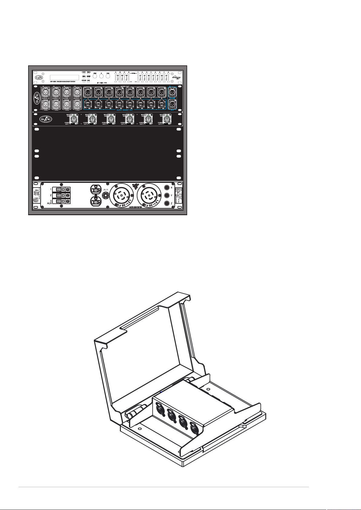
DASnet Splitter:(NEW)
Steel case intended for distribution of analog audio, monitoring data and power to multiple
devices.
It includes: - One input power (1 x powerCon true 1) and 3 power outputs (3 x powercon
NAC3MPB).
- One audio+monitoring data input, and three audio + monitoring data ouputs
DASnet - 7
Page 8
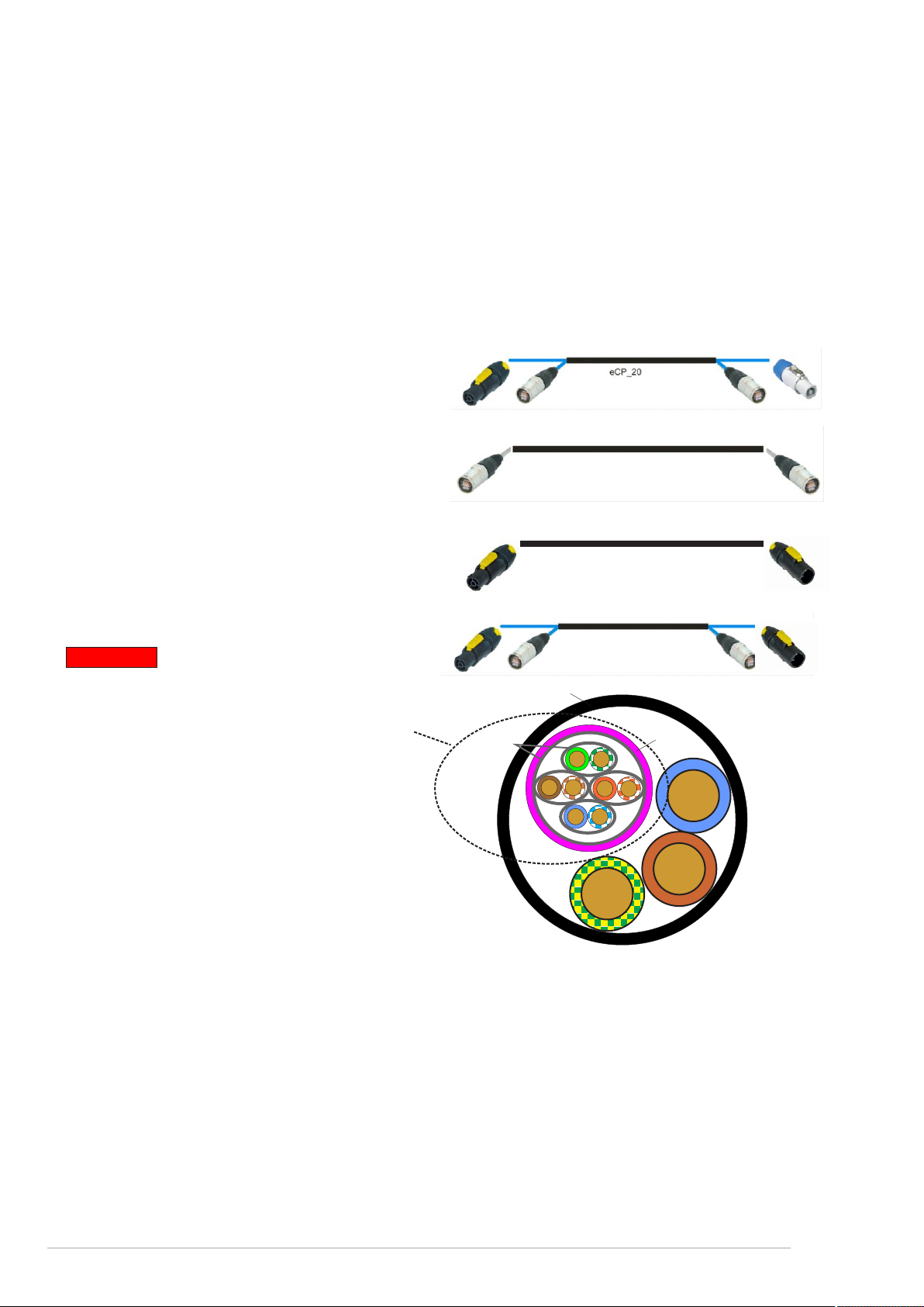
DASnet cables
With each system cabling and patch panels are provided. It is very important to use the system
with the intended cables to prevent electromagnetic interferences between the analog audio signal,
the DASnet data and the power. Be sure to check the specifications provided by the cable
manufacturer. It is also especially important when installing connectors yourself, to note that when
termination is not accurate, a cable will be unable to achieve its maximum performance and could
have interferences.
There are 4 different types of cables.
- The main feeds which include power and a STP, CAT7 cable. These cables are named
eCP_xx (xx refers to cable length).
- The links between cabinets (aero40A/Convert15A/LX-218CAnet), which are STP CAT7
cables. Cable code eC_09
- Power Links between cabinets.Cable code Plink1_09
- Links for RoadNet series. Power+STP CAT7. eCPk_1/eCPk_5
Important
The main feed cable eCP_xx has the following structure:
Jacket
STP CAT 7 cable with Aluminium Shield for
each individual pair and a main aluminium
AL Shield
Shield.
The main Shield has to be soldered to the
etherCon housing.
The eC_09 cable is a CAT5e cable with
global Aluminium Shield.
ecP_xx: Power cable 3x2.5mm + CAT7 4x (2 x 0.14mm )
2 2
The pin out of the EtherCon to XLR is the following on the eCP cables:
etherCon XLR
1 Orange-White Audio+ 2
2 Orange Audio- 3
3 Green-White Audio Earth 1
4 Blue
5 Blue-White
6 Green Data Earth 1
7 Brown-White Data- (A) 3
8 Brown Data+ (B) 2
Jacket
DASnet - 8
Page 9
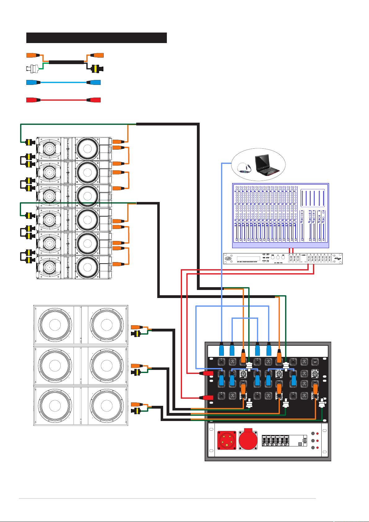
2. BASIC CONNECTIONS
Power + DASnet data + analog audio
DASnet RS485
Analog audio
aero 40A
USB - Rs485
LX-218CA_net
sub L
DASnet DASnet DASnet
IN IN IN
Audio Audio Audio
IN IN IN
DASnet DASnet DASnet
IN IN IN
Audio Audio Audio
IN IN IN
IN IN IN
OUT OUT OUTOUT OUT OUT
1 2 3
OUT OUT OUT
IN IN IN
OUT OUT OUTOUT OUT OUT
1 2 3
OUT OUT OUT
6 x MCB 16A “C” 1pol.
1 x RCD 40A 30mA4pol.
FI-Schalter
FI4030mA 4pol.
EDIT
top L
I
o
L1
L2
L3
DASnet - 9
Page 10

2.1 BASIC CONNECTIONS with new DASnet patch and Splitter
Power + DASnet data + analog audio
DASnet RS485
Analog audio
aero 40A
USB - Rs485
LX-218CA_net
PA Left
PUSH
PUSH
PUSH
231
2
1
3
PUSH
231
231
231
2
2
1
1
1
3
3
2
2
1
3
2
1
1
3
3
2
2
1
1
3
3
2
2
1
1
3
3
2
1
1
3
6 x MCB 16A “C” 1pol.
1 x RCD 40A 30mA4pol.
EDIT
2
2
1
3
3
2
1
3
FI-Schalter
FI4030mA 4pol.
PUSH
231
2
2
1
1
3
3
2
1
3
2
2
1
3
3
L1
I
L2
o
L3
IN OUT1 OUT2 OUT3
DASnet - 10
Page 11

software
DASnet - 11
Page 12
1. INTRODUCTION
DASnet is the monitoring and control software for D.A.S. Audio powered sound systems and digital
signal processors.
This manual covers the installation and use of D.A.S.Audio´s proprietary software package
known as DASnet. This software is a remote control application running under Microsoft Windows TM
and is compatible with the following D.A.S. Audio products:
The DSP-2060A Speaker Management System
The DSP-4080 Speaker Management System
The Convert 15A Speaker System
The LX-218CA Speaker System
The aero 40A Line Array System
The aero 20A Line Array System
The software has been designed to allow all these products to be connected to a computer through a
variety of interfaces and will permit full remote control of any combination of up to 256 devices. The
maximum distance covered is up to 1000meters.
The software can be downloaded from D.A.S. Audio website:
www.dasaudio.com/en/support/software-2/
Always check the website for updates. There is a firmware updater (DASloader) software for the
cabinets that can be used to update the firmware of the cabinets incluing improvements and new
added features. The software can also be downloaded from the D.A.S. website.
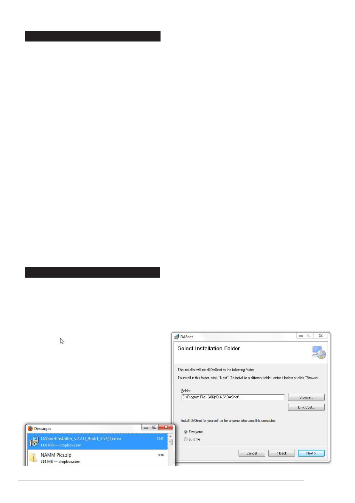
2. INSTALLING THE SOFTWARE
Please note that this software will not run under WindowsTM 3.1 or 3.11. It is designed for WindowsTM
95/98/NT4 2000, ME, XP, Windows 7 and Windows 8.
Follow these steps to install your copy of DASnet for Windows TM
Once the installer has been downloaded from the website double click and install it. Select the
installation folder and continue untill the software has been succesfully installed.
Pay attention to Administrator mode in W7
and W8 system. To execute the program
once it has been installed the user has to
run it as an administrator on W7.
DASnet - 12
Page 13
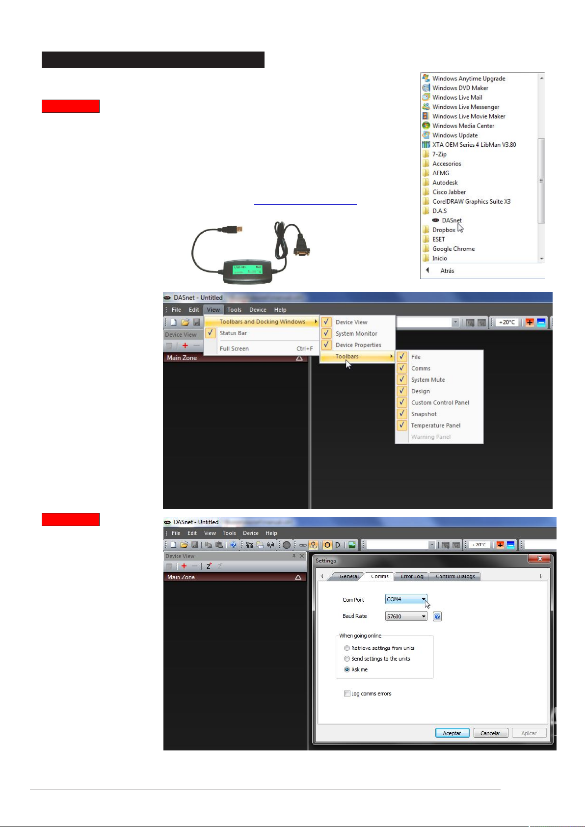
3. STARTING THE SOFTWARE
The installation procedure will have created an entry in the ‘Programs’
list off the ‘Start’ menu.
Important
The software bases its communication system on the RS-485 format. It
is necessary to convert that format at the access port of the control
computer. The converter will create a virtual COM port on the computer
that the software will detect automatically.
The basic connection uses an RS-485 to USB converter; the
recommended device is the kksystems ( ) RS-485 to www.kksystem.com
USB converter (refer to the installation and operation manual for more
details).
Easy to install the
device works as a
virtual COM port and
allows daisy chaining
multiple units. From
the PC to the first unit,
from this one to the
second, etc.
Wh en r unn ing th e
software for the first
time, make sure that all
windows are active. Go
to the view menu and
activate all of them.
Important
On the tools menu
select the COM port
number that uses the
installed converter to
allow communication
with the devices
(cabinets). Baud rate
must be 57600!!
Besides this, the user
can select getting the
parameters from the
units (retrieve settings)
or send the settings to
the units from the
computer or ask the
user everytime the
system goes on-line.
DASnet - 13
Page 14
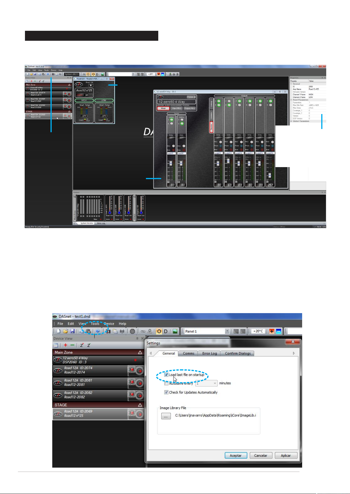
4. LAYOUT OF THE MAIN WINDOW
A double click on any device will display its “front view” for editing of audio properties. Non-audio
properties are shown in the Properties panel on the right hand side of the main window.
A cabinet control panel currently
active
Device View:
- cabinets
- DSP´s
active in the network
Properties window:
- system´s name
- amplifier´s channels
- DASnet ID number
A DSP control panel
currently active
In the above example all devices are off-line, as shown by the red indicator on each unit in the
Device View and the System Monitor View. When connected and on-line, the indicators will be
green. A yellow flashing indicator means there is a problem (like a protection or load erro
detection) - check on the control panel of the device for more details.
Before looking at the details of a device´s controls and properties, here are a few general
pointers about using the software:
- The last saved file can automatically be opened when the software is started by setting
the option in the Tools --> Options --> General Tab:
DASnet - 14
Page 15
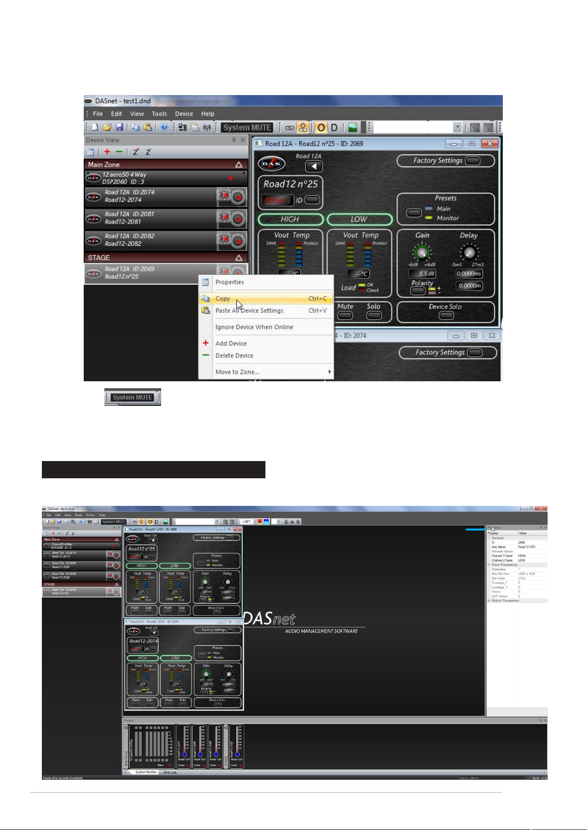
- Settings can be copied between units either using the buttons on the toolbar (which
uses the currently selected cabinet) or by using the right-click context menu on the unit´s “front
view” or in the Device View:
- The global Mute works from either the toolbar, menu, or by pressing ´Ctrl +M` on the
keybord.
- The error log is stored to a file called “Logfile.txt” which is stored in the same directory as the
program executable file.
5. REORGANISING THE WINDOW
To move inner windows about, pick them up by their title bar:
Pick window up by the
title bar and begin to
drag....
DASnet - 15
Page 16
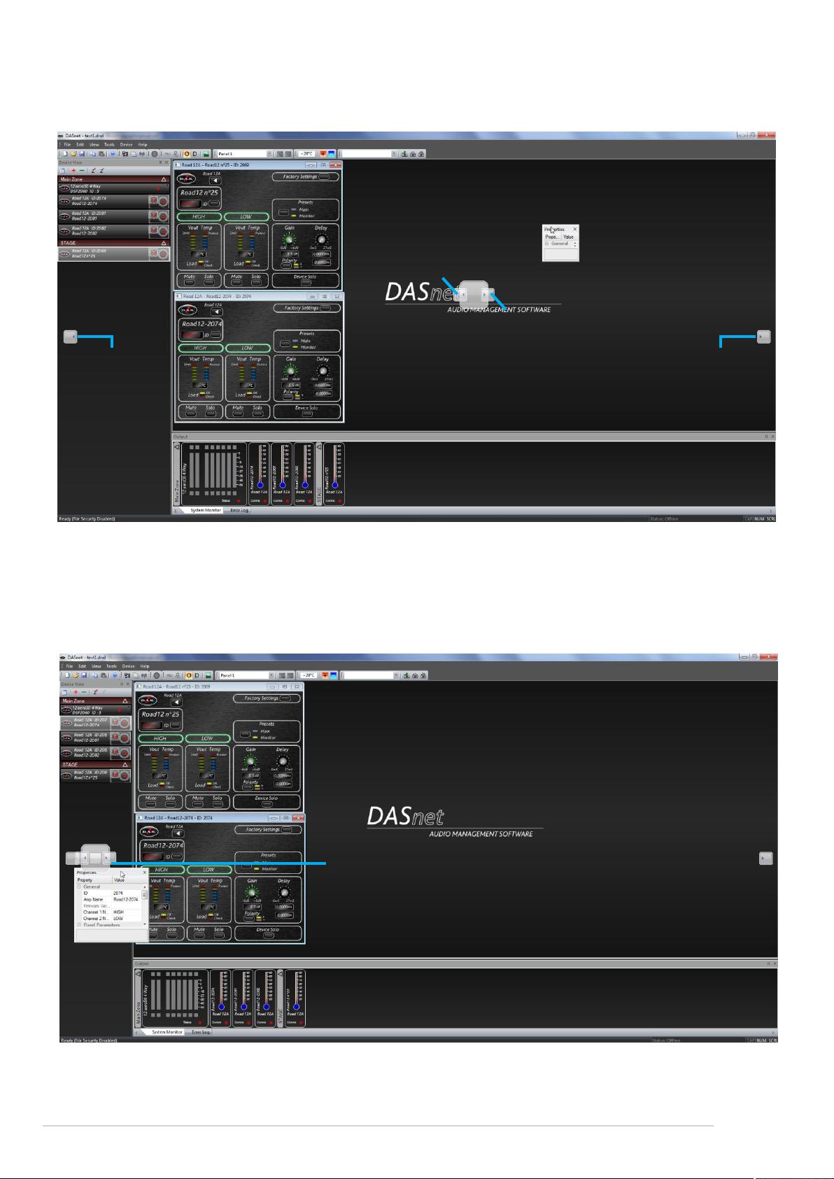
For example to move the properties window and re-dock it, pick up the properties window by its
title bar and begin to drag it. This will make a number of docking options anchors appear - these
look like this:
Drop here the dock
above system monitor
down
left hand side of window
Drop here the dock above
Drop here the
dock fully
down left hand
side of window
system monitor down
right hand side of window
Drop here the
dock fully
down right
hand side of
window
Drop the window on one of the anchors to dock it in the new position, as shown above. Similary, the
system monitor window can be docked either top or bottom of the main window, and either fully
across this window, or bracketed by the device view and/or prorperties window.
The Device View and properties window can be combined into a single tabbed window by picking
either up and dragging it directly onto the other window where a new anchor will appear.
Drop on left or right of this anchor to dock
properties to the left or right of the device window.
Drop on the centre of the anchor to dock as a pair
of tabbed panes
To separete out the windows again, just click on the tab of the window and drag and drop it as
required to select a new position.
DASnet - 16
Page 17
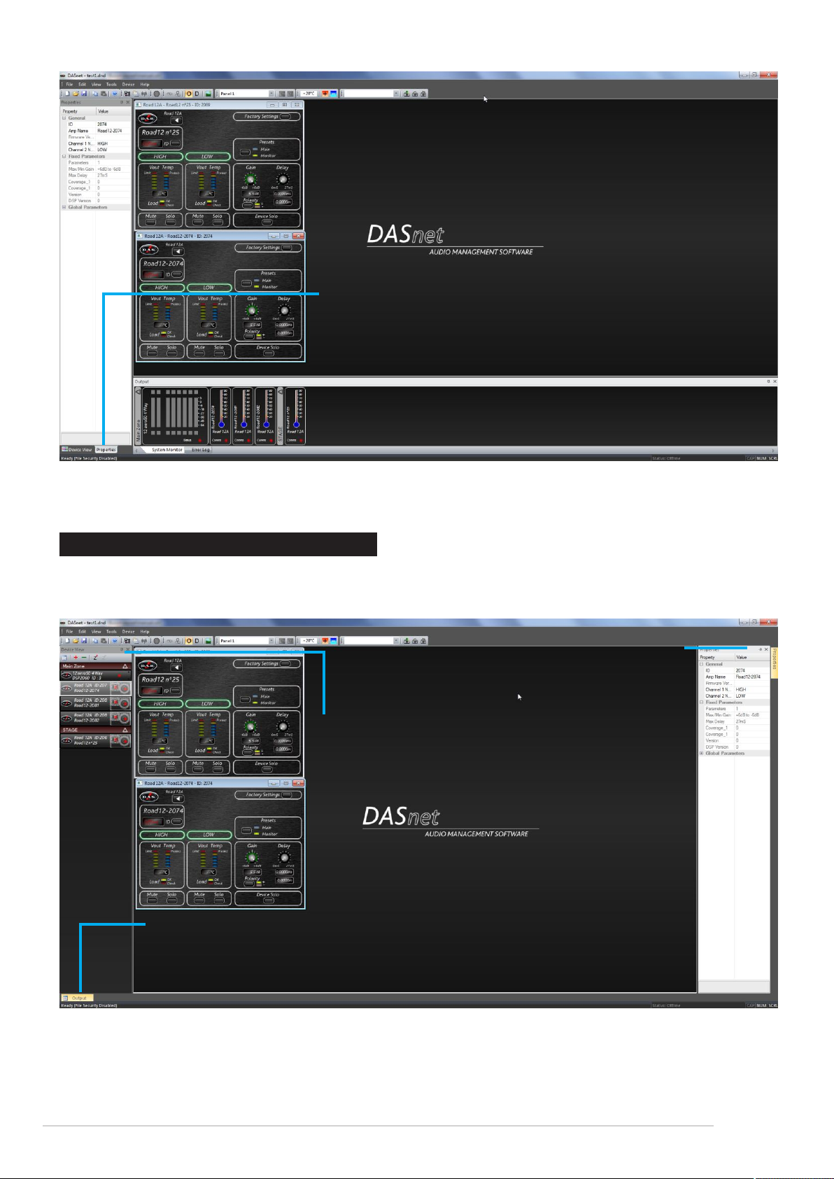
Click and drag the tab to
separate the properties out
from the device view again
Windows can also be left floating by dragging them from their current positions and just dropping
them on the main background.
6. AUTO-HIDING WINDOWS
All inner windows can be set to “auto hide”, so they disappear into the edge of the main window when
not required to maximise available screen area, but make them quickly available if necessary.
Properties view set to autohide as pin is horizontal. Click
pin to change this...
Device View is not set up
to auto-hide as pin is
upright...
Output (System monitor & error log) is set
to auto-hide and has hidden itself. Move
over the tab to make it reappear...
Remember, if any windows have been closed they can be reinstated throught the menu View
-->toolbars and docking windows.
DASnet - 17
Page 18
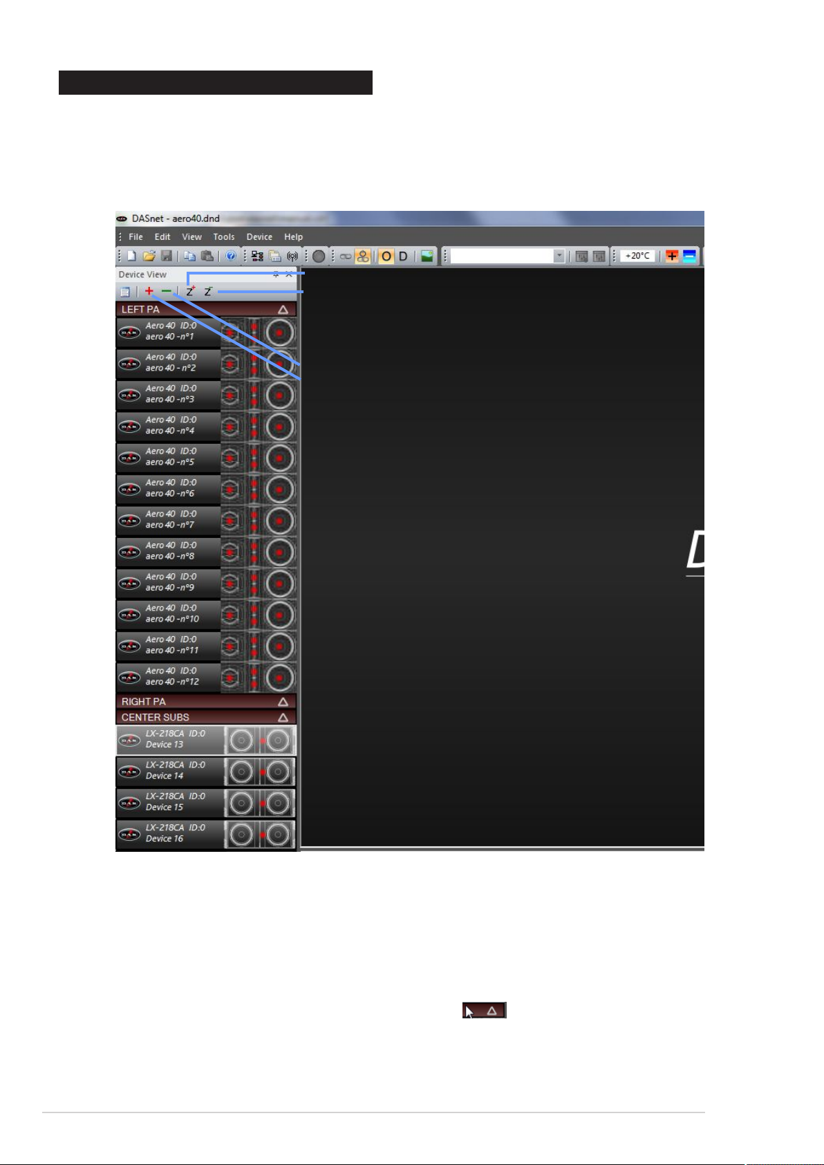
7. ZONING DEVICES
The Zones shown in the Device View and System Monitor windows allow groups of devices to be
logically arranged to reflect their physical locations more accurately than just one large list of units.
The example below has different cabinets split into three zones, and units re-ordered to make it
easier to locate them on the screen.
Adding “zones”
Removing “zones”
Left PA Zone contains 12 x aero 40A
Removing decives (only off-line)
Adding devices
Another zone “Center Subs” contains all
the LX-218CA_net subs
Things to know about the zones:
- There is always a master (main) zone, which you can rename (Letf PA) but you can never
get rid of.
- New zones can be added using the Z+ button at the top of the Device View.
- Devices can be moved into new zones just by clicking on them and dragging them to the
required zone. They can also be re-ordered within a zone in the same way.
- Zones can be renamed by double click on their names.
- Zones can be expanded and collapsed using the in the zone header.
- Files will remember the zone layouts including expand / collapse status when you save
them.
DASnet - 18
Page 19
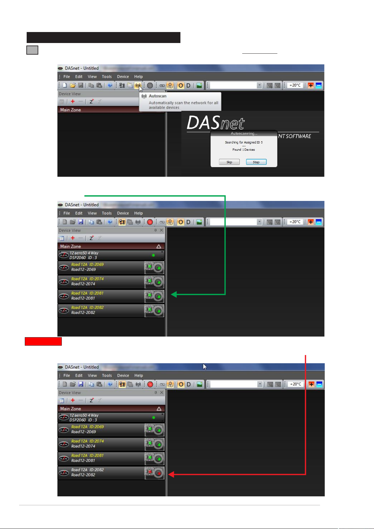
8. COMMUNICATION WITH THE DEVICES
8.1 The simplest way of adding units to the net is by using the AutoScan option (remember to
specify the COM port on the tools / options menu). The entire process will take approximately 90
When the scanning process ends, all connected devices (on line) appear on the device view
window in green.
Important: only connected devices will appear on the main window. If the communication with
any of the devices is lost after being detected, the unit will appear in red colour and physically in
the cabinet the Comms / ID led will not light up:
DASnet - 19
Page 20
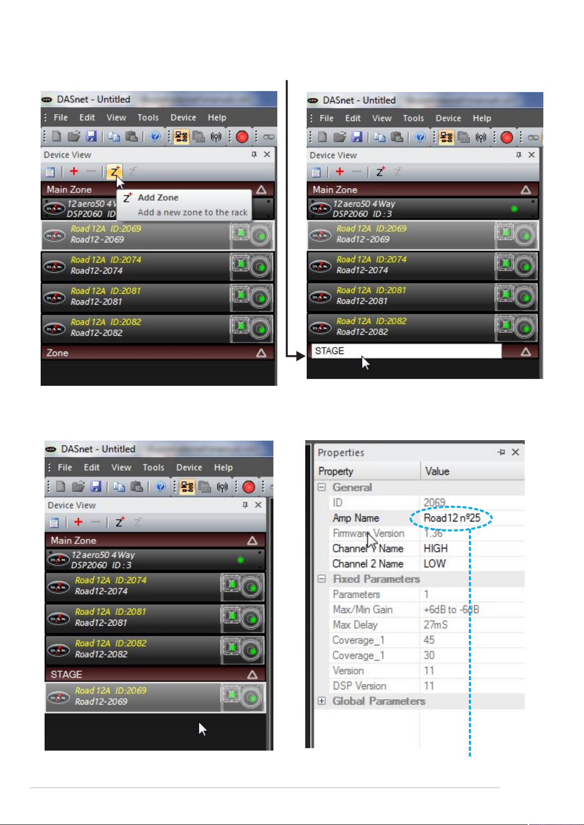
On line devices can be assigned to different zones just by clicking and dragging them. First step
is to add new zones and then, rename them. In this case the zone has been named stage.
The unit Road 12A ID:2069 has been moved to the Zone named STAGE. Besides this, the unit
could be renamed on the properties window (this name will remain in the memory of the device!):
The ID number on the cabinets is unique and will never change. The user can rename the
cabinets by using an easier code, for instance numbers: Road 12 nº25 etc
DASnet - 20
Page 21

8 .2 I f t he s y st e m
configuration is always
the same, because it is a
fixed installation or the
set up remains the same
between shows, a
*.dnd file can be saved
on the computer and the
user could work with it as
an starting point.
Once you have your
syste m r ead y w hil e
c o m m un i c a t i o n i s
running save the file, in
this case test1.dnd
Once the file has been saved close the software and re open it again. Instead of going to the
autoScan menu, open test1.dnd file first:
At this moment the saved configuration has been recalled but still there is NO communication
between the computer and the devices. To do that go to ON Line button on the software (Ctrl +
Q):
DASnet - 21
Page 22

When going on line the software will ask the user:
It is up to the user to decide if parameters on the software
file have to be sent to the devices (Send) OR settings from
the cabinets have to be imported to the software. In this
case we will use the settings from the units (Retrieve).
Immediately when pressing OK all the units on the
test1.dnd file will be On Line (without doing the scanning
process):
system´s name
The name of the system can be changed by the user. Once the change is done, the name will remain
the same even though a factory settings reset is done.
IMPORTANT: The first time the user connects the cabinets with the PC it is highly recommendable to
name all your inventory devices with numbers for instance.
IMPORTANT: The baud rate must remain at 57600 to ensure compatibility with all connected
devices.
IMPORTANT: The safest method of connection to avoid accidentally changing any device settings is
to select “Retrieve Settings from units” as this will upload all devices properties and parameters to
the computer.
IMPORTANT: Remember to save your system before closing DASnet to avoid having to rescan the
system every time you open the software. All window positions, zones, and screen layouts (so
positions of the Device View, Properties and System Monitor) are also saved.
DASnet - 22
Page 23

8.3 There is another way of adding (manually) devices to the net. If the DASnet ID number of
the cabinet is know (it is always on the cabinet´s sticker) just adding a virtual device and setting
the ID number on its properties menu the system will automatically connect.
On the graph is shown the net with 3 Road 12A on line:
When being on line a new device (Road 12A ID:0 Device 5) is added and the user writes the ID
number on the properties menu:
After introducing the ID number and “enter” the cabinet will be on line.
DASnet - 23
Page 24

9. DEVICE VIEW WINDOWS - cabinets
DASnet has been designed to monitor and control parameters on the connected devices. There
are two types of devices, cabinets and digital signal processors.
Cabinets
Road 12A_net
Road 15A_net
Processors
DSP-2060A
DSP-4080
LX-218CA_net
Convert 15A
aero 40A
aero 20A
9.1 Cabinets - Road series
The basic window is activated just by a double click on the device. Example: Device number 25,
Road 12A
system´s name
ID knob
amplifier´s channel
temperature
limiter monitoring
load monitoring
basic device view window
- System´s name: defined by the user on the properties window.
- The ID button allows the user to identify the cabinet physically. The ID LED on the
amplifier will blink once per second for a few seconds.
If communication is working the comms LED will be blinking
faster and continuosly.
D.A.S. AUDIO S.A. (Valencia), MADE IN SPAIN
Road 12A_net
RISK OF ELECTRIC SHOCK
DO NOT OPEN
CAUTION
DO NOT EXPOSE THIS EQUIPMENT
TO RAIN OR MOISTURE
IN OUT
20080011
This operation could be done the other way.
By pressing the identify knob on the cabinets
amplifier the device window on the left main
DASnet menu, will blink.
N1918
ON/PROTECT
SIGNAL
INPUT
IDENTIFY/
COMMS
LOOP
THRU
AC INPUT 115V 4A 50Hz/60Hz
MAIN
MONITOR
IDENTIFY
- Amplifier´s channel: for each amplifier channel there is a vumeter referred to the limiter
threshold. There is also a temperature
vumeter that senses amplifiers temperature:
AC OUTPUT
MAX. 5 UNITS IN PARALLEL
DASnet - 24
Page 25

- Load monitoring: for each amplifier channel there is a continuos impedance system
control that indicates if the speakers are working properlly(green) or not (red):
when a speaker is not
working the device lits in
yellow
On the “advanced view” parameters as gain/delay/preset/polarity/mute and solo are available:
delay control
presets control
gain control
advanced device view window
- Gain control: this control is for the complete cabinet (not per amplifier channel). From -20dB
to +6dB. Value can be entered using the keyboard or the gain control of the software.
- Delay control: this control is for the complete cabinet (not per amplifier channel). From 0ms
to 27ms.
- Presets: on the Road series two presets are available: Main and Monitor
With the Road series two presets are
avialble. By default (factory settings) the
cabinet is a wedge monitor and Monitor
preset is active. By pressing the button on
the cabinet or on the software Main preset
is activated (Main preset boosts low and
high end).
- Polarity: inverts the polarity of the complete cabinet.
- Mute/Solo: per amplifier channel or per cabinet. When SOLO is activated ALL the other
devices on the net are muted.
DASnet - 25
Page 26

Preset changes are bidirectional so if a preset is changed on the software it will be also changed
on the cabinet. And vice versa, a change on the cabinet will be shown as well on the software.
IMPORTANT: all DASnet control parameters (gain, delay, presets, mute, solo...etc) are stored on
the micro controller included in the amplifier. This means that after switching off the system all values
of the parameters will remain the same in memory for the next time the system is switched on.
For instance: if a cabinet has these settings Gain +3dB, delay 5.033ms:
When it is switched off all values are saved in the internal micro controller memory, so next time
the system is powered the parameters remain the same Gain +3dB, delay 5.033ms.
IMPORTANT: when the user is not sure about the internal settings in the micro controller (delay,
gain etc) the best thing is to do a factory settings reset. Factory settings puts all the parameters
at zero. Device name will remain the same (in this case Road 12 -nº25). Monitor preset will be
active.
But also physically by pressing the preset knob (holding during a few seconds) while powering
the cabinet (on the Road 12A / 15A and LX-218CA).
DASnet - 26
Page 27

9.2 Cabinets - Convert 15A
Convert 15 A basic view window; DASnet ID 2114:
system´s name
ID knob
amplifier´s channel
temperature
limiter monitoring
load monitoring
basic device view window
- System´s name: defined by the user on the properties window.
- The ID knob allows the user to identify the cabinet physically. The ID LED on the amplifier
will blink once per second duirng a few seconds.
If communication is working the comms
LED will be blinking faster and permanently.
To identify the cabinet on the software the user
AMP.
PROTECT
SIGNAL
/LIMIT
IDENTIFY
/COMMS
MODE - NUMBER OF UNITS HF GAIN
COVERAGE HIGH PASS FILTER
ON
Convert 1560A
Digitally Convertible Dispersion
IDENTIFY
OK
TO UNLOCK,
PRESS AND HOLD OK
FOR 2 SECONDS
should press the button up on the “joystick” of
the Convert 15A panel; the device window will
IN OUT
blink on DASnet.
SIGNAL
N1918
RISK OF ELECTRIC SHOCK
DO NOT EXPOSE THIS EQUIPMENT
DO NOT OPEN
CAUTION
TO RAIN OR MOISTURE
INPUT
LOOP
THRU
D.A.S. AUDIO S.A. (Valencia) MADE IN SPAIN
- Amplifier´s channel: for each amplifier channel there is a vumeter refered to the limiter
threshold. There is also a temperature
vumeter that senses amplifier´s chanel
temperature:
IMPORTANT: Convert 15A amplifier has been
designed to work up to 40ºC ambient
temperature at clipping conditions.
If amplifier´s temperature is over 60ºC the
internal fan will start working. If amplifier´s
temperature is over 70ºC output voltage on the
amplifier will be reduced to ensure its durability.
ID DASNET
DASnet - 27
Page 28

- Load monitoring: for each amplifier channel there is an impedance system control that
indicates if the speakers are working properlly(green) or not (red):
when a speaker is not
working the device
lits in yellow
On the “advanced view” parameters as gain/delay/preset/polarity/mute and solo are available:
presets control
delay control
gain control
advanced device view window
- Gain control: this control is for the complete cabinet (not per amplifier channel). From -20dB
to +6dB. Value can be entered using the keyboard or the gain control of the software.
- Delay control: this control is for the complete cabinet (not per amplifier channel). From 0ms
to 100ms.
- Polarity: inverts the polarity of the complete cabinet.
- Mute/Solo: per amplifier channel or per cabinet. When SOLO is activated ALL the other
devices on the net are muted.
DASnet - 28
Page 29

- Presets on the Convert 15A, 36 presets are available (see user´s manual for more details).
Preset can be changed using DASnet or the panel “joystick”.
Here are listed the DASnet preset selection possibilities:
Mode selection
Point Source (PS)
Curved Source (CS)
Number of Units
on PS mode fixed to 1
on CS mode up to 4 units in the array
DASnet preset menu
High Frequenecy (for array Shading)
controls the gain of the compression drivers
Can be set up at 0, -3dB or -6dB
High Pass Filter (48dB/oct)
OFF (there is an internal X-over at 50Hz)
63Hz
80Hz
100Hz
DASnet - 29
Page 30

Preset changes are bidirectional so if a preset is changed on the software it will be also changed
on the cabinet. And vice-versa, a change on the cabinet will be shown as well on the software.
IMPORTANT: all DASnet control parameters (gain, delay, presets, mute, solo...etc) are stored on
the micro controller included in the amplifier. This means that after switching off the system all values
of the parameters will remain the same in memory for the next time the system is switched on.
IMPORTANT: when the user is not sure about the internal settings in the micro controller (delay,
gain etc) the best thing is to do a factory settings reset. Factory settings puts all the parameters
at zero. Device name will remain the same (in this case C15A-2).
Factory settings reset can be done via software: (check that gain and delay are set up at zero)
default factory
settings
IMPORTANT: The default or factory settings on the Convert 15A are:
Mode: Point Source
Number of Units: 1 Unit
High Frequency: 0dB
Highpass Filter: OFF
Physically if the user wants to do a reset or factory settings, the control joystick and the display
has to be used:
By clicking right button select menu
Press OK for 2 seconds
OK
OK
number 2 - utilities
OK
OK
When Restore menu is active
press and hold for 2 seconds
DASnet - 30
Page 31

9.3 Cabinets - aero 40A
aero 40A basic view window; DASnet ID 2405:
system´s name
system´s name
ID knob
amplifier´s channel
temperature
limiter monitoring
load monitoring
basic device view window
- System´s name: defined by the user on the properties window.
- The ID knob allows the user to identify the cabinet physically. The ID LED on the amplifier
will blink once per second during a few seconds.
If communication is working the comms LED will
blink faster and permanently.
AMPLIF.
PROTECT
SIGNAL
/LIMIT
IDENTIFY
COMMS/
NUMBER OF UNITS
THROW HIGH PASS FILTER
ON
IDENTIFY
OK
TO UNLOCK,
PRESS AND HOLD OK
FOR 2 SECONDS
To identify the cabinet on the software the user
should press the button up on the “joystick” of
the Convert 15A panel; the device window will
IN OUT
blink on DASnet.
RISK OF ELECTRIC SHOCK
DO NOT OPEN
CAUTION
DO NOT EXPOSE THIS EQUIPMENT
TO RAIN OR MOISTURE
SIGNAL
INPUT
LOOP
THRU
- Amplifier´s channel: for each amplifier channel there is a vumeter refered to the limiter
threshold. There is also a temperature
vumeter that senses amplifier´s chanel
temperature:
IMPORTANT: aero 40A amplifier has been
designed to work up to 40ºC ambient
temperature at clipping conditions.
If amplifier´s temperature is over 60ºC the
internal fan will start working. If amplifier´s
temperature is over 70ºC output voltage on the
amplifier will be reduced to ensure its durability.
N1918
D.A.S. AUDIO S.A. (Valencia)
MADE IN SPAIN
DASnet - 31
Page 32

- Load monitoring: for each amplifier channel there is an impedance system control that
indicates if the speakers are working (green) or not (red), as it happens on the other
cabinet models (see Convert 15A or Road series).
On the “advanced view” parameters as gain/delay/preset/polarity/mute and solo are available:
presets control
delay control
gain control
advanced device view window
- Gain control: this control is for the complete cabinet (not per amplifier channel). From -20dB
to +6dB. Value can be entered using the keyboard or the gain control of the software.
- Delay control: this control is for the complete cabinet (not per amplifier channel). From 0ms
to 100ms.
- Polarity: inverts the polarity of the complete cabinet.
- Mute/Solo: per amplifier channel or per cabinet. When SOLO is activated ALL the other
devices on the net are muted.
DASnet - 32
Page 33

- Presets on the aero 40A, 200 presets are available (see user´s manual for more details).
Preset can be changed using DASnet or the panel “joystick”.
Here are listed the DASnet preset selection possibilities:
Number of Units
Selects the number of cabinets in the array
compensating the acoustical coupling for low and mid range
with different Low Shelf gain filters:
DASnet preset menu
Throw
5 presets are available. It enables a High Shelf EQ
to have a more uniform distribuiton over the distance
Long
+3
Long-Mid
+1.5
H Shelf EQ f=6k3Hz Q 0.71
0
-1.5
-3
Mid
Mid-Short
Short
High Pass Filter (48dB/oct)
OFF (there is an internal X-over at 45Hz)
63Hz
80Hz
100Hz
DASnet - 33
Page 34

Preset changes are bidirectional so if a preset is changed on the software it will be also changed
on the cabinet. And vice versa, a change on the cabinet will be shown as well on the software.
IMPORTANT: all DASnet control parameters (gain, delay, presets, mute, solo...etc) are stored on
the micro controller included in the amplifier. This means that after switching off the system all values
of the parameters will remain the same in memory for the next time the system is switched on.
IMPORTANT: when the user is not sure about the internal settings in the micro controller (delay,
gain etc) the best thing is to do a factory settings reset. Factory settings puts all the parameters
at zero. Device name will remain the same (in this case aero 40A-15).
Factory settings reset can be done via software: (check that gain and delay are set up at zero)
default factory
settings
IMPORTANT: The default or factory settings on the aero 40A are:
Number of Units: 1 Unit
Throw: Mid Throw
Highpass filter: OFF
Physically if the user wants to do a reset or factory settings, the control joystick and the display
has to be used:
By clicking right button select menu
Press OK for 2 seconds
OK
OK
number 2 - utilities
OK
OK
When Restore menu is active
press and hold for 2 seconds
DASnet - 34
Page 35

9.4 LX-218CA_net
- System´s name: defined by the user on the properties window.
- The ID knob allows the user to identify the cabinet physically. The ID LED on the amplifier
will blink once per secong during a few seconds.
If communication is working the comms
LED will be blinking faster and permanently.
system´s name
ID knob
amplifier´s channel
temperature
limiter monitoring
basic device view window
LX-218CA.net
D.A.S. AUDIO S.A. (Valencia), MADE IN SPAIN
RISK OF ELECTRIC SHOCK
To identify the cabinet on the software the
user should press identify knob on the
amplifier panel; the device window will
DO NOT OPEN
CAUTION
DO NOT EXPOSE THIS EQUIPMENT
TO RAIN OR MOISTURE
IN OUT
blink on DASnet.
SIGNAL
INPUT
IDENTIFY/
COMMS
LOOP
THRU
100-230 V~ 50/60Hz 900W
- Amplifier´s channel: for each amplifier channel there is a vumeter
referred to the limiter threshold. There is also a temperature
vumeter that senses amplifiers temperature:
ON/PROTECT
SIGNAL/CLIP
R F
CARDIOID
PRESET
IDENTIFY
AC INPUT
N1918
CARDIOID
F
R
OMNI
F
F
DASnet - 35
Page 36

- Load monitoring: for each amplifier channel there is an impedance system control that
indicates if the speakers are working (green) or not (red):
On the “advanced view” parameters as gain/delay/preset/polarity/mute and solo are available:
presets control
gain control
delay control
advanced device view window
- Gain control: this control is for the complete cabinet (not per amplifier channel). From -20dB
to +6dB. Value can be entered using the keyboard or the gain control of the software.
- Delay control: this control is for the complete cabinet (not per amplifier channel). From 0ms
to 34ms.
- Presets: on the LX-218CA_net two presets are available: Front and Rear
When the cabinet´s knob is pressed rear preset is active. Rear preset
must be used only when cabinet is facing backguards in conjunction with
other ones facing to the front to create a caridoid subwoofer set up.
CARDIOID
F
R
- Polarity: inverts the polarity of the complete cabinet.
- Mute/Solo: per amplifier channel or per cabinet. When SOLO is activated ALL the other
devices on the net are muted.
DASnet - 36
Page 37

Preset changes are bidirectional so if a preset is changed on the software it will be also changed
on the cabinet. And vice versa, a change on the cabinet will be shown as well on the software.
IMPORTANT: all DASnet control parameters (gain, delay, presets, mute, solo...etc) are stored on
the micro controller included in the amplifier. This means that after switching off the system all values
of the parameters will remain the same in memory for the next time the system is switched on.
For instance: if a cabinet has these settings Gain +6dB, delay 15.038ms:
When it is switched off all values are saved in the internal micro controller memory, so next time
the system is powered the parameters remain the same Gain +6dB, delay 15.038ms.
IMPORTANT: when the user is not sure about the internal settings in the micro controller (delay,
gain etc) the best thing is to do a factory settings reset. Factory settings puts all the parameters
at zero. Device name will remain the same (in this case LX-2056). Front preset will be active.
Factory settings reset can be done via software: (check that gain and delay are set up at zero)
But also physically by pressing the preset knob (holding during a few seconds) while powering
the cabinet.
DASnet - 37
Page 38

9.5 Cabinets - aero 20A
aero 20A basic window; DASnet ID 7237:
system´s name
ID number
basic window: device view
- System´s name: defined by the user on the properties window.
- The ID knob allows the user to
identify the cabinet physically. The ID
LED on the amplifier will blink once per
second during a few seconds.
If communication is working the comms
LED will blink faster and permanently.
To identify the cabinet on the software the user
1
3
6
12
NUMBER OF UNITS
IDENTIFY/COMMS
should press the button on amplifier´s panel; the
device window will blink on DASnet.
amplifier´s channel
temperature
Limiter monitoring
Impedance check control
RISK OF ELECTRIC SHOCK
CAUTION
DO NOT EXPOSE THIS EQUIPMENT
N1918
D.A.S. AUDIO S.A. (Valencia) MADE IN SPAIN
2
4
IN OUT
8
16
SIGNAL/
LIMIT
SIGNAL INPUT
TO RAIN OR MOISTURE
20
LOOP THRU
DO NOT OPEN
LONG
MID
SHORT
THROW
ON/PROTECT
- Amplifier´s channel: for each amplifier channel there is a vumeter refered to the limiter
threshold. There is also a temperature vumeter that senses amplifier´s chanel temperature:
DASnet - 38
Page 39

- Load monitoring: for each amplifier channel there is an impedance system control that
indicates if the speakers are working (green) or not (red), as it happens on the other cabinet
models (see Convert 15A or Road series).
On the “advanced view” parameters as gain/delay/preset/polarity/mute and solo are available:
presets control
gain control
delay control
advanced device view window
- Gain control: this control is for the complete cabinet (not per amplifier channel). From -6dB to
+6dB. Value can be entered using the keyboard or the gain control of the software.
- Delay control: this control is for the complete cabinet (not per amplifier channel). From 0ms to
28ms.
- Polarity: inverts the polarity of the complete cabinet.
- Mute/Solo: per amplifier channel or per cabinet. When SOLO is activated ALL the other
devices on the net are muted.
DASnet - 39
Page 40

- Presets on the aero 20A: 24 presets are available for the aero 20A (see user´s manual for
more details). The default preset (factory settings) sets a flat acoustic response (1unit, Mid
Throw).
Presets can be selected using the software or the knobs at the amplifier´s panel.Here are
listed the DASnet preset selection possibilities:
Number of Units
Selects the number of cabinets in the array
compensating the acoustical coupling for low and mid range
with different High Shelf Bell filters:
DASnet preset menu
Throw
3 presets are available. It enables a High Shelf EQ
to have a more uniform distribuiton over the distance
Long
+3
H Shelf EQ f=2kHz Q 0.71
0
-3
Mid
Short
DASnet - 40
Page 41

Preset changes are bidirectional so if a preset is changed on the software it will be also changed
on the cabinet. And vice versa, a change on the cabinet will be shown as well on the software.
IMPORTANT: all DASnet control parameters (gain, delay, presets, mute, solo...etc) are stored on
the micro controller included in the amplifier. This means that after switching off the system all values
of the parameters will remain the same in memory for the next time the system is switched on.
IMPORTANT: when the user is not sure about the internal settings in the micro controller (delay,
gain etc) the best thing is to do a factory settings reset. Factory settings puts all the parameters
at zero. Device name will remain the same (in this case aero 20A-1).
Factory settings reset can be done via software: (check that gain and delay are set up at zero)
default factory
settings
IMPORTANT: The default or factory settings on the aero 40A are:
Number of Units: 1 Unit
Throw: Mid Throw
But also physically by pressing the preset throw knob (holding during a few seconds) while
powering the cabinet.
N1918
D.A.S. AUDIO S.A. (Valencia) MADE IN SPAIN
2
1
4
3
8
6
16
12
NUMBER OF UNITS
IDENTIFY/COMMS
SIGNAL INPUT
20
IN OUT
SIGNAL/
LIMIT
LOOP THRU
RISK OF ELECTRIC SHOCK
DO NOT OPEN
CAUTION
DO NOT EXPOSE THIS EQUIPMENT
TO RAIN OR MOISTURE
LONG
MID
SHORT
THROW
ON/PROTECT
step 1
press Throw
knob
NUMBER OF UNITS
UNIT NAME STAGE / VENUE
MAX. 5@230V / 2@115V UNITS AERO 20A
AC INPUT
115/230 V~ 50/60Hz 620W
THROW
ID DASNET
Step 2
AC OUTPUT
turn on the
PowerCon
DASnet - 41
Page 42

10. DEVICE VIEW WINDOWS - processors
DASnet has been designed to monitor and control parameters on the connected devices. There
are two types of devices, cabinets and processors.
Processors
DSP-2060A
DSP-4080
The DSP window on DASnet has three main options: mixer, input EQ and ouput EQ:
mixer
input EQ
output EQ
10.1 On the Mixer menu three options are available: Source, limiters and Linking.
Source is the input matrix and can be used for routing inputs and outputs.
In this case output 1 of the processor uses
inputs A and B, outputs2&3 use input A and
outputs 4&5&6 use input B.
Besides the input / output routing on the
Source menu the user can invert the
polarity of the output channel (phase)
Mute / Gain per output is available as well.
The delay per output is also accessible
from the Source menu.
DASnet - 42
Page 43

On the Linking menu the user can link channels. When two channels are linked all parametres
are copied on both channels; gain, Eqs, delay, Xovers. Warning: polarity doesn´t link between
linked channels:
Output channels 1&2 are linked.
Output channels 5&6 are linked.
Check that delay on channels 1 and 2 is
the same.
Phase is not the same on those two
channels although they are linked.
On the Limiters menu the user can set up the limiter threshold, attack and release time per output.
There are two ways of working with the limiters, automatic (auto ON) mode which uses the Xover
frequencies on each output to calculate the time constants. The user only sets the threshold. Or
manual (auto OFF) mode; in this case the user defines the attack and release times.
Auto limiter on / off
Threshold (level)
Peak limiter (clip)
Threshold level will set up the RMS limiter value and Clip Level Above will set up the Peak
limiter.
RMS value can be calculated with the following formula: (in dB)
limiter threshold = 20xlog (Vd/0.775) -Amp GAIN (dB)
where Vd is the desired voltage for the load.
Power (Watts)= Vd / Z
2
DASnet - 43
Page 44

For example:
D.A.S. Audio LX-218C subwoofer. 2400W RMS, 4ohm cabinet (2x18”)
D.A.S. Audio D-100 amplifier. Amp Gain36dB.
Using the formula Vd = 2400*4 = 97.8volts
Limiter threshold = 20log (97.8/0.775)-36 =+6dB
The time constants are set by the high
pass filter frequency for that channel on
automatic mode:
On the previous calculation for an LX-218C the limiter screen would be like this one (auto OFF):
threshold + 6dB
attack time 45ms (related to 33Hz Lr24 used to process the cabinet)
release time 45ms x 16
Peak limiter +3dB (refered to +6dB)
DASnet - 44
Page 45

10.2 On the Input EQ menu the user can select input A or B and set up up to 8 parametric Eqs
per input channel.
10.3 On the Output EQ menu the user can select the output channel and set up up to 9
parametric EQs and Xovers per channel:
DASnet - 45
Page 46

On the DSP window presets are available. New Store or recall can be done via DASnet:
DASnet - 46
Page 47

11. LINK MANAGER
Using this functionality parameters on different systems can be linked. The user can create Link
groups (or parameters) and when varying a parameter in one cabinet the others will be affected
as well.
The link Manager opens a new screen where different links can be created.
New Link has been created. GAIN
DASnet - 47
Page 48

The devices on the net appear on the right part of the screen. From any device a list of
parameters can be selected. In this case we have selected the GAIN of the Road 12 -2069
More cabinets (Road 12 - 2074) are selected:
For now we have linked the system´s gain of two cabinets: ID 2069 and ID 2074
DASnet - 48
Page 49

In order to work with the link manager the user has to activate it. Linking Status ON:
We have linked the gain of two of the stage monitors. If we vary the gain of one of them, the
other´s gain will automatically change:
With the link manager Gain/delay/mute/amplifier
name/preset/polarity can be linked on the cabinets.
We are creating a new group for those 2 monitors. Preset:
DASnet - 49
Page 50

Now besides the system´s gain the preset is linked on both cabinets:
Important
Example:
When working with aero 40A systems the link manager will be very usefull to adjust the system´s
settings. In this particular case the user should create a link with the parameter number of units.
Then will be very simple just by changing on one of the cabinets the number of units parameter to
adjust the desired value.
DASnet - 50
Page 51

Link Manager Creating groups on software versions later than 1.1.0
With the integration of the aero 20A in the software, new improved and added features are also
available.One of the most significant ones refers to the procedure of creating groups of parameters
or linking parameters. Creating links of parameters can be done as described in section 11 or
following this new procedure:
In the device view tree on the left a device multi-selection can be done by clicking Ctrl + left mouse
click or with Shift+left mouse click.
In this example two aero 20A are selected by
using left click + Shift.
With the devices selected press right click on the
mouse and the following menu appears on the
screen:
A new option is now available: link manager
Inside the Link Manager menu different parameter
options are displayed. This menu and the options
will vary depending on the system selected. For
the aero 20A the options displayed are, Mute per
amplifier Channel, Number of units and Throw.
DASnet - 51
Page 52

Once the parameter Number of units has been selected, a new link is created. By default the link´s
name shown is Link 1. Name can be defined by the user. In this case we use Number of units.
With this procedure a link has been created in all the selected devices in a faster way than described
in section 11.
DASnet - 52
Page 53

12. CUSTOM PANELS
With DASnet on Designer Mode the user can create Custom Panels which could contain faders,
knobs, buttons to be associated to different system parameters. The utility of this tool is that if the link
manager is activated, the user can modify parameters on more than one system at once with just a
simple control. In this case Link Manager is activated and remember that all the cabinet gains are
linked:
Linking is active
We are going to add a fader control:
designer mode
new custom panel
DASnet - 53
Page 54

Once the fader has been added on its properties window an image can be associated to it.
Besides an image a parameter can be associated.
fader
parameter
fader
We are going to assign Road 12-nº25 gain to the fader´s parameter. Remember that besides
this, all cabinets´ gain have been linked previously.
no parameter has been
asigned to the fader
parameter selection:
Road 12-nº25 gain
Now the fader is controlling the Road 12 -nº25 gain. As the gain of all devices has been linked using
the link manager (section 11), the fader acts as a general volume control of all of them.The scale of
the fader can be drawn. User can change font and colour.
fader´s
parameter
scale
parameters
DASnet - 54
Page 55

An image can be associated to the fader control (fader appearance):
fader´s image
image library
manager
There is an image library were buttons / leds / knobs / faders are stored. The user can also
import new images to the library (see page 37). The custom panel background colour can also
be changed. An image can be set up as background as well:
selecting
background colour
or background
image
Remember that to create a custom panel the user must be on Designer mode. Once the Custom
panel has been created it will be saved with the *.dnd file. To operate with it change to Operator
mode.
DASnet - 55
Page 56

Operate Mode
The fader controls
system´s gain
gain -3.4dB
New background colour for the custom panel and operate mode. Check that fader control all
cabinet´s gain. (-3.4dB).
On a Custom Panel a button and a led to control the mute operation . If we come back to the
Designer Mode we can add new controls to the panel: LED & BUTTON
come back to the Designer Mode we can add new controls to the panel: LED & BUTTON
DASnet - 56
Page 57

LED Appearance: BIGyellowLED selected as LED image:
Button Appearance: BIGshinyButton selected as button image:
DASnet - 57
Page 58

Road 12-nº25 HIGH Channel mute assigned to the LED as parameter:
Road 12-nº25 HIGH Channel mute assigned to the Button as parameter:
DASnet - 58
Page 59

The Custom panel can include text and images from the image library manager. In this case the
GAIN fader controls all the system and the mute buttons and leds both channels of the Road 12nº25: (shown mute active on high channel)
The Custom panel can be as sophistacated as the user may want. Here is another example of a
complete system and a custom panel with gain controls and mutes per amplifier channel.
DASnet - 59
Page 60

13. IMAGE LIBRARY MANAGER
DASnet includes an image library manager with predefined images. The user can create new
folders and incorporate new images to the library. These images can be used on the custom
panels or as a background.
DASnet - 60
Page 61

Appendix 1. Quick aero40A system configuration
When rigging for the first time the aero 40A, the most important thing is identifying the order in
which the cabinets have been flown to re-order them on the software.
For instance, let´s consider the DASnet identifying process for one side of the PA composed of
8 aero40A.
1 - We have taken notes and the order in which the cabinets have been flown is the following:
cabinet number 1 (top): DASnet ID 2864
cabinet number 2: DASnet ID 2399
cabinet number 3: DASnet ID 2115
cabinet number 4: DASnet ID 2429
cabinet number 5: DASnet ID 2874
cabinet number 6: DASnet ID 2323
cabinet number 7: DASnet ID 2626
cabinet number 8: DASnet ID 2605
2 - Second step is to do an “autoscan” on
DASnet. The software recognizes all the
connected devices (in this case 8
aero40A). BUT they don´t appear in the
physical order in which they have been
flown.
3 - Next step will be re-ordering and re-naming the cabinets accordingly to the physical order.
The cabinet 2864 is number one. The user
has to locate it on the software, changing
its name and moving it to the right position:
The aero 40A 2864 is aero 40A number
one regarding the physical rigging order.
We have to change its name and re
locate it on the software.
DASnet - 61
Page 62

Once cabinet aero 40A 2864 has been renamed to aero 40A-1 the user has do the same with
all the cabinets. Remember that the new name has to refect the physical position of the cabinet
in the cluster.
aero 40A 2323 is going to be aero 40A-6
We have re named cabinets 1,6,5, 8 and
continue with aero 40A 2626 which is
number 7 in the array.
All cabinets have been re named:
DASnet - 62
Page 63

4 - Next step is to re-order the cabinets in the zone. Just click on the device view window on the
desired cabinet, drag it to its correct position:
Now all cabinets have been re-ordered.
5 -Next Step on Link manager --> create new link --> number of units
open link manager menu
new links have to be created
(number of units)
The user has to include in this new group all the aero 40A units. Doing this when a user
changes the number of units preset in one cabinet it will affect all the others as well.
DASnet - 63
Page 64

We have created a new link named “number of units”. Among all the possible parameters,
select all the aero 40A (from 1 to 8) the parameter number of units.
1
3
2
Repeat the steps 1 to 3 with all the
aero 40A in your system. In this
case from A40-1 to A40-8
New link manager group created:
number of units
Activate this option on the software for to enable the link manager groups:
DASnet - 64
Page 65

6 - Next step is to create a group with the parameter HighPass Filter using link manager:
Create a new group with the
parameter HighPass Filter for all
the aero 40A units.
With these two links, number of units and HighPass Filter the user can start the tuning of the
system.
NOTE: There are more parameters that could be linked as the Throw of the cabinets.
DASnet - 65
Page 66

Appendix 2. Move to Main Window
Multi-selection of devices is available on version 1.5 using Shift or Ctrl + left mouse click. When a
unit (or more) has been selected on the Device View window by doing right click on the mouse the
menu Move to main window is displayed.
This command allows to move the selected devices to the main screen.
DASnet - 66
Page 67

This is an example of a 24 x aero 20A system. All devices have been moved and organised in
the main window:
DASnet - 67
Page 68

Appendix 3. Snapshots
One way of changing parameters in a very fast way when using DASnet with audio
processors and networkable cabinets is by the use of snapshots. It is like a fast “preset recall” that is
stored in the DASnet *.dnd file, not in the devices!
As a sample we are going to create two snapshots in a processor, one will link the ouput 5 of the
processor to the input A, and the other will be linking the output 5 of the processor to inputs A and C.
To create a new snapshot, go to the snapshot window and click +, add new snapshot. The new
snapshot stores the existing parameters in the software.
add snapshot
When creating the snapshot the out 5 of the processor is using inputA. Name is defined by user;
in this case we call the snapshot SUB MIX input A:
DASnet - 68
Page 69

First Snapshot has been created. Now we modify parameters in the DSP and create the second
one. We will link out 5 with inputs A and C:
Once the parameters have been changed the new snapshot can be created. We will name it
SUB MIX input A&C.
DASnet - 69
Page 70

We have both snapshots created. To change from one to the other simply select the desired one in
the snapshots control panel.
snapshot SUB MIX input A
snapshot SUB MIX input A & input C
DASnet - 70
 Loading...