


HEF
OPERATING INSTRUCTIONS
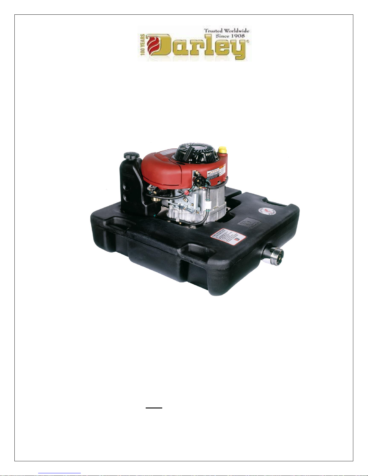
HEF DOLPHIN FLOAT PUMP
Corporate Office: Pump Manufacturing: Apparatus Division:
325 Spring Lake Drive 1051 Palmer St. 920 Kurth Rd.
Itasca, Illinois 60143-2072 Chippewa Falls, WI 54729 Chippewa Falls, WI 54729
800-323-0244, fax (708) 345-8993 800-634-7812, Fax (715) 726-2656 800-527-0068, Fax 726-2648
WWW.DARLEY.COM
This manual is for DARLEY FIRE PUMP:
Model: HEF Pump Serial Number: ________


Introduction
This manual provides information for the use and understanding of this manual, correct
operation, maintenance, troubleshooting of the Darley HEF Dolphin Float Pump, definition of
terms, and contacts. Please read and understand these instructions thoroughly before putting
this system into service. Doing so will ensure optimum performance and long life of your
Darley Floating Pump.
This manual is divided into eight sections, each section details an important portion of this
manual and pump.
Section 1 Definition of Symbols
Section 2 Operation
Section 3 Pump Assembly/Disassembly
Section 4 Components
Section 5 Maintenance Schedule
Section 6 Troubleshooting
Section 7 Definition of Terms and Operating Characteristics of
Pumps.
Section 8 Contacts

Section 1
Definition of Symbols
Prepared by: RJG Rev. A
Approved by: TED Date: 03/04/10
Revised by: TED Rev. Date: 30June2015
1200627.doc

IMPORTANT
Throughout this manual will find Caution, Warning and Danger symbols.
Please pay close attention to these symbols as they are for your safety.
- Signifies an imminently hazardous situation that
could result in death or serious injury.
- Signifies a potentially hazardous situation that could
result in death or serious injury.
- Signifies a potentially hazardous situation that
might result in minor or moderate injury.
- Signifies a potentially hazardous situation that
might result in property damage.
Intentionally ignoring any of these identified hazards is not
recommended. W.S. Darley does not advise such actions or take
responsibility for the actions of any operator of this unit.
Prepared by: RJG Rev. A
Approved by: TED Date: 03/04/10
Revised by: TED Rev. Date: 30June2015
1200627.doc

Section 2
Operation
Prepared by: RJG Rev. A
Approved by: TED Date: 03/04/10
Revised by: TED Rev. Date: 30June2015
1200627.doc
Operating Instructions
For Darley “DOLPHIN” Floating Fire Pump
Do not use this pump for hose testing. Such testing could
result in major pump or engine damage. Such damage may cause
explosion, overheating of the engine and/or pump, and bodily harm.
PREPARATIONS FOR PUMPING
Make sure to read the engine instruction manual before usage.
Check the engine oil level before starting the engine.
Check the fuel level before starting the engine.
Do not run the pump dry or at high speed unless it is placed in water of adequate
depth.
Connect the discharge hose to the pump.
Ensure the discharge breather check valve; located near the Darley emblem on
the float; is working, clean and clear of debris.
Start the engine.
Place float pump in the water immediately after starting. This Float pump is self-
priming due to a flooded suction. The pump will prime more quickly if the engine
is run at lower speeds.
Slowly open the engine throttle once the pump is primed and discharging water.
Recommendations
Do not allow unusual elevation of the discharge hose, this may
cause the float to overturn.
When pumping salt water or dirty water, flush pump with clean water after usage.
Prepared by: RJG Rev. A
Approved by: TED Date: 03/04/10
Revised by: TED Rev. Date: 30June2015
1200627.doc

Section 3
Maintenance (Assembly/Disassembly)
Prepared by: RJG Rev. A
Approved by: TED Date: 03/04/10
Revised by: TED Rev. Date: 30June2015
1200627.doc

PUMP DISASSEMBLY
Drawing DHC1204
For pump overhaul or disassembly follow the corresponding steps
Drain oil and gas from engine, ensuring there is no fuel in the tank or lines.
o There may be small residual amounts of oil remaining in the engine (up to 8
ounces), which may read at the very end of the dipstick (see photo below).
If the oil level is up as high as the H on the dipstick, below the ADD mark,
the oil needs to be further drained prior to tipping the engine.
Remove the (3) bolts holding the support plate (6) to the float (5).
Remove the pump discharge pipe from the pump discharge.
Remove the engine and pump by tilting the engine forward and lifting the
assembly clear of the float. Only tilt the engine so the exhaust faces down.
Titling the engine in other directions may damage the engine. It
may also cause fuel to leak out causing a hazardous spill.
The suction head (11) may now be removed from pump casing (8) using the
tapped pusher holes if necessary.
Remove the impeller bolt (15). Remove the engine spark plug and insert a clean
rope into bore to prevent engine rotation and ease removal of the impeller bolt
(15) (see photo below).
Prepared by: RJG Rev. A
Approved by: TED Date: 03/04/10
Revised by: TED Rev. Date: 30June2015
1200627.doc
 Loading...