


MANUAL
ENGLISH
GIG-244CFX V1
Order code: D2288
Highlite International B.V. – Vestastraat 2 – 6468 EX – Kerkrade – the Netherlands

GIG-244CFX |
|
Table of contents |
|
Warning ............................................................................................................................................................................... |
2 |
Unpacking Instructions................................................................................................................................................. |
2 |
Safety Instructions ......................................................................................................................................................... |
2 |
Operating Determinations .......................................................................................................................................... |
4 |
Connection with the mains......................................................................................................................................... |
4 |
Return Procedure.......................................................................................................................................................... |
5 |
Claims.............................................................................................................................................................................. |
5 |
Description of the device................................................................................................................................................. |
6 |
Features .......................................................................................................................................................................... |
6 |
Overview ........................................................................................................................................................................ |
6 |
Control Elements................................................................................................................................................................ |
7 |
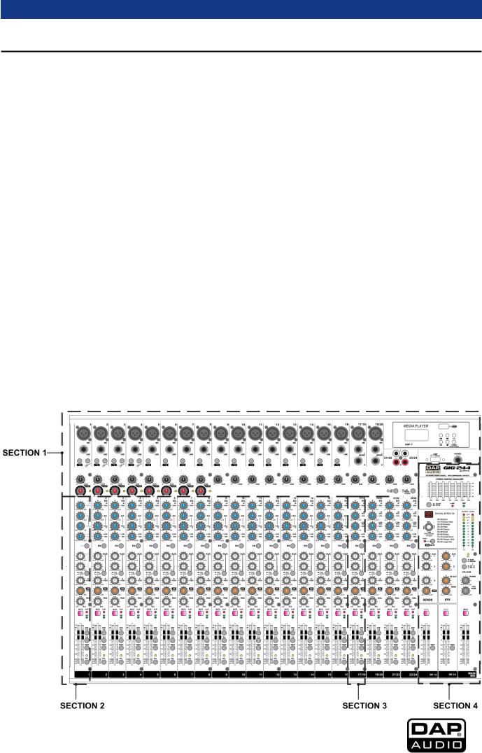
Elements section 1 ........................................................................................................................................................ |
7 |
Elements section 2 ........................................................................................................................................................ |
8 |
Elements section 3 ...................................................................................................................................................... |
10 |
Elements section 4 ...................................................................................................................................................... |
11 |
Backside ....................................................................................................................................................................... |
14 |
Media player (Optional) ................................................................................................................................................ |
15 |
Installation......................................................................................................................................................................... |
16 |
Set Up and Operation ..................................................................................................................................................... |
16 |
Ready to start .............................................................................................................................................................. |
16 |
Set up and connection ............................................................................................................................................. |
16 |
Connection Cables ......................................................................................................................................................... |
17 |
Preset List GIG-244CFX ................................................................................................................................................... |
18 |
Maintenance.................................................................................................................................................................... |
19 |
Replacing the Fuse..................................................................................................................................................... |
19 |
Troubleshooting ............................................................................................................................................................... |
19 |
Product Specifications.................................................................................................................................................... |
19 |
Dimensions........................................................................................................................................................................ |
21 |
Notes .................................................................................................................................................................................. |
22 |
Order code: D2288 |
1 |
|
|
|
|
|
|

GIG-244CFX
Warning
Unpacking Instructions
Immediately upon receiving this product, carefully unpack the carton and check the contents to ensure that all parts are present and have been received in good condition. Notify the dealer immediately and retain packing material for inspection if any parts appear damaged from shipping or the carton itself shows signs of mishandling. Save the carton and all packing materials. In the event that a fixture must be returned to the factory, it is important that the fixture be returned in the original factory box and packing.
Your shipment includes:
GIG-244CFX mixing console
3-pin IEC power cable 1,5m
User manual
Safety Instructions
Every person involved with the installation, operation and maintenance of this system has to:
•be qualified
•follow the instructions of this manual
Before you initial start-up, please make sure that there is no damage caused by transportation. Should there be any, consult your dealer and do not use the system.
To maintain perfect condition and to ensure a safe operation, it is absolutely necessary for the user to follow the safety instructions and warning notes written in this manual.
Please consider that damages caused by manual modifications to the system are not subject to warranty.
This system contains no user-serviceable parts. Refer servicing to qualified technicians only.
Order code: D2288 |
2 |
|
|
|
|
|
|

GIG-244CFX
IMPORTANT:
The manufacturer will not accept liability for any resulting damages caused by the non-observance of this manual or any unauthorized modification to the system.
Never let the power-cord come into contact with other cables! Handle the power-cord and all connections with the mains with particular caution!
Never remove warning or informative labels from the unit.
Never use anything to cover the ground contact.
Never leave any cables lying around.
Do not insert objects into air vents.
Do not connect this system to a dimmer pack.
Do not switch the system on and off in short intervals, as this would reduce the system’s life.
Do not open the device and do not modify the device.
Do not drive the inputs with a signal level bigger, than required to drive the equipment to full output.
Do not plug Mics into the console (or stage box) while Phantom Power is on. Also mute the monitor / Pa system when turning Phantom Power on or off. Allow the system to adjust for a couple of seconds, before setting the input gains.
Only use system indoor, avoid contact with water or other liquids.
Avoid flames and do not put close to flammable liquids or gases.
Always disconnect power from the mains, when system is not used. Only handle the power-cord by the plug. Never pull out the plug by tugging the power-cord.
Always operate the unit with the AC ground wire connected to the electrical system ground.
Make sure you don’t use the wrong kind of cables or defective cables.
Make sure that the signals into the mixer are balanced, otherwise hum could be created.
Make sure you use DI boxes to balance unbalanced signals; All incoming signals should be clear.
Make sure that the available voltage is not higher than stated on the rear panel.
Make sure that the power-cord is never crimped or damaged. Check the system and the powercord from time to time.
Please turn off the power switch, when changing the power cord or signal cable, or select the input mode switch.
Extreme frequency boosts in connection with a high input signal level may lead to overdriving your equipment. Should this occur, it is necessary to reduce the input signal level by using the INPUT control.
To emphasize a frequency range, you don’t necessarily have to move its respective control upward; try lowering surrounding frequency ranges instead. This way, you avoid causing the next piece of equipment in your sound path to overdrive. You also preserve valuable dynamic reserve
(“headroom”)
Avoid ground loops! Always be sure to connect the power amps and the mixing console to the same electrical circuit to ensure the same phase!
If system is dropped or struck, disconnect mains power supply immediately. Have a qualified engineer inspect for safety before operating.
If the system has been exposed to drastic temperature fluctuation (e.g. after transportation), do not switch it on immediately. The arising condensation water might damage your system. Leave the system switched off until it has reached room temperature.
If your Dap Audio device fails to work properly, discontinue use immediately. Pack the unit securely (preferably in the original packing material)and return it to your Dap Audio dealer for service.
Repairs, servicing and electric connection must be carried out by a qualified technician.
For replacement use fuses of same type and rating only.
WARRANTY: Till one year after date of purchase.
Order code: D2288 |
3 |
|
|
|
|
|
|

GIG-244CFX
Operating Determinations
This system is not designed for permanent operation. Consistent operation breaks will ensure that the system will serve you for a long time without defects.
If this system is operated in any other way, than the one described in this manual, the product may suffer damages and the warranty becomes void.
Any other operation may lead to dangers like short-circuit, burns, electric shock, etc.
You endanger your own safety and the safety of others!
Connection with the mains
Connect the device to the mains with the power-plug.
Always pay attention, that the right color cable is connected to the right place.
International |
EU Cable |
UK Cable |
US Cable |
Pin |
L |
BROWN |
RED |
YELLOW/COPPER |
PHASE |
N |
BLUE |
BLACK |
SILVER |
NEUTRAL |
|
YELLOW/GREEN |
GREEN |
GREEN |
PROTECTIVE GROUND |
Make sure that the device is always connected properly to the earth!
Improper installation can cause serious damage to people and property!
Order code: D2288 |
4 |
|
|
|
|
|
|

GIG-244CFX
Return Procedure
Returned merchandise must be sent prepaid and in the original packing, call tags will not be issued. Package must be clearly labeled with a Return Authorization Number (RMA number). Products returned without an RMA number will be refused. Highlite will not accept the returned goods or any responsibility. Call Highlite 0031-455667723 or mail aftersales@highlite.nl and request an RMA prior to shipping the fixture. Be prepared to provide the model number, serial number and a brief description of the cause for the return. Be sure to properly pack fixture, any shipping damage resulting from inadequate packaging is the customer’s responsibility. Highlite reserves the right to use its own discretion to repair or replace product(s). As a suggestion, proper UPS packing or double-boxing is always a safe method to use.
Note: If you are given an RMA number, please include the following information on a piece of paper inside the box:
01) Your name
02) Your address
03) Your phone number
04) A brief description of the symptoms
Claims
The client has the obligation to check the delivered goods immediately upon delivery for any shortcomings and/or visible defects, or perform this check after our announcement that the goods are at their disposal. Damage incurred in shipping is the responsibility of the shipper; therefore the damage must be reported to the carrier upon receipt of merchandise.
It is the customer's responsibility to notify and submit claims with the shipper in the event that a fixture is damaged due to shipping. Transportation damage has to be reported to us within one day after receipt of the delivery.
Any return shipment has to be made post-paid at all times. Return shipments must be accompanied with a letter defining the reason for return shipment. Non-prepaid return shipments will be refused, unless otherwise agreed in writing.
Complaints against us must be made known in writing or by fax within 10 working days after receipt of the invoice. After this period complaints will not be handled anymore.
Complaints will only then be considered if the client has so far complied with all parts of the agreement, regardless of the agreement of which the obligation is resulting.
Order code: D2288 |
5 |
|
|
|
|
|
|
GIG-244CFX
Description of the device
Features
The DAP GIG-244CFX is a professional compact mixer, which gives you great quality and better reliability than ever before. It is really ideal for gigs, recording and fixed PA installations.
Ultra-low noise discrete MIC Preamps with +48V Phantom Power
18 MIC Input Channels with XLR and 16 balanced Line Inputs
Insert IN/OUT and Compressor control
Low Cut for MIC Input
4 Auxiliary controls
Highly accurate 12-segment output level meter
2 Stereo Input Channels with mono XLR Input and TRS Jack
2 Stereo Input Channels with RCA Jack
3-band EQ with sweepable MID and Clip LED on each MIC channel
4-band EQ and Clip LED on Stereo channels
4 AUX Send POST/PRE per channel for monitoring, external effects and internal effects
4 AUX Send volume control
EFX return on AUX, MAIN and dedicated jack output
Mute and PFL function for each channel
60mm Fader for level control
GR1-2, GR3-4 and Main L/R bus assign for each channel
Balanced XLR & TRS outputs for Main Mix
Built-in 24-bit DSP effect with 100 presets
USB-port to connect the GIG-244CFX to your PC/ laptop
Built-in Media player
Internal switch-mode power supply for maximum flexibility 100-240V
Fuse: T1,25AL/250V
Dimensions: 622 x 405 x 65 mm (LxWxH)
Weight: 9,35 kg
Overview
Order code: D2288 |
6 |
|
|
|
|
|
|

GIG-244CFX
Control Elements
Elements section 1
1. MIC INPUT JACKS (CHs 1 to 19/20)
Electronically balanced XLR-type inputs for connecting low-impedance microphones. The input provides extremely low noise and low hum signal processing. When connecting a microphone make sure that the pin assignment is correct. Always make sure to read the manual of the microphone you want to connect. The XLR-inputs are not suitable for connecting line level signals like an additional mixing console, FX-unit, etc. You have to use the LINE-inputs, when connecting this kind of equipment.
The balanced XLR input can be connected to microphones, DI boxes and multicores.
2. LINE INPUT JACKS (CHs 1 to 16)
Electronically balanced inputs (¼" jack connector) for connecting a keyboard, CD player, mixer, etc. You can connect balanced or unbalanced signal sources to the LINE input. Do not connect signal devices to a channel’s MIC and LINE input at the same time. This will cause mutual interference, which results in level reduction.
3. LOW CUT
Press the LOW CUT switch to activate the high-pass filter which blends out low-frequency
noise (100 Hz, 18 dB/octave). This function can be used to cut the humming sound or to prevent resonances of low frequencies, when the speakers are placed in close distance.
4. INSTRUMENT
Press this button to transform the input into an hi-impedance input. It can be used if you connect a guitar directly on the input.
5. GAIN CONTROL
With the GAIN control you can adjust the MIC or LINE input-sensitivity, while optimally matching the incoming signals to the mixer’s internal operation level. Be sure to set this control fully counter-clockwise before you connect or disconnect a signal source to or from one of the inputs.
STEREO: The value range between 0 and +50 refers to the microphone input, indicating the degree of amplification applied to the input's signal.
6. COMPRESSOR CONTROL
Adjust the amount of compression applied to the channel. Turn the control to the right to increase the compression ratio and the output gain will automatically be adjusted. The result is smoother, even more dynamics, because louder signals are attenuated when the overall level is boosted.
Order code: D2288 |
7 |
|
|
|
|
|
|
 Loading...