


PARMA™
Dual Kitchen Faucet
Grifo para cocina a función doble
Robinet de cuisine à fonction double
Model / Modelo / Modèle
D423058
Installation Instructions
Instrucciones para la instalacion
Guide d'installation
Toll free service / Linea telefonica gratis / Numéro sans frais
|
US: 1-888-328-2383 |
Less than 0.25% lead content |
Canada: 1-800-487-8372 |
|
Introduction
Congratulations on your purchase of the Danze Parma Dual Kitchen faucet with spray. This faucet is designed to operate using the standard single control manual valve, or automatically without the need to touch a faucet part to start and stop the faucet stream. The hands free mode delivers water through the spout at a predetermined temperature, and will automatically shut off (you can set the timing), by activating the sensor located on the spout. When you have greasy or dirty hands, now you can start and stop the water without soiling the handle.
The guide is in English, Spanish and French languages for your convenience.
Before you begin , we recommend you review the installation steps as this faucet is unique.
About your Faucet
Table of Contents |
|
|
PG |
English section |
1 |
Spanish section |
12 |
French section |
23 |
•Operates hands-free or with single control handle
•Durable, smooth operating ceramic disc valve
•Brass vegetable spray
•AC or DC power
•Timed shut-off hands-free operation
•Includes hook-up hoses and fittings
•For DC hook-up: uses four C type batteries, not included
•Includes a step-by-step installation demonstration video in DVD format
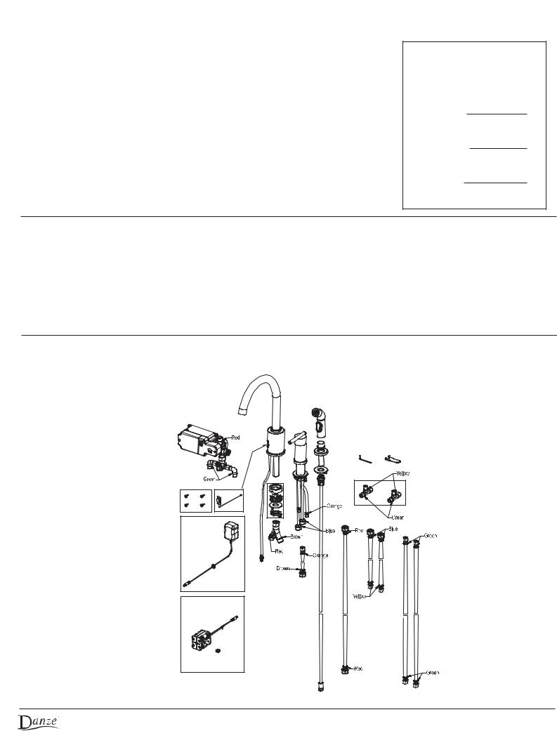
Product Tour
Check to make sure you have the following parts indicated below.
HINT: lay parts out on floor and connect all hoses loosely to understand arrangement before starting. If parts are missing, do not start this project. Call service number for assistance.
© 2009 Danze, Inc. All rights reserved. |
1 |
Before you begin
This faucet is designed to be installed in 1 1/2" diameter faucet mounting holes. Typical installation uses 3 mounting holes located 4" center to center with the fittings mounted per the illustrations. Because the spout, hand valve, and spray are connected below the sink by hoses, you have flexibility to locate these fittings in different order or location to suit the user. The hands free sensor should be oriented to avoid accidental triggering. See further notes below.
Shut off main water supply before installation.
The power to the hands free mechanism can be supplied using battery pack (DC), or from your 110V household current (AC) using the power cord with transformer supplied.
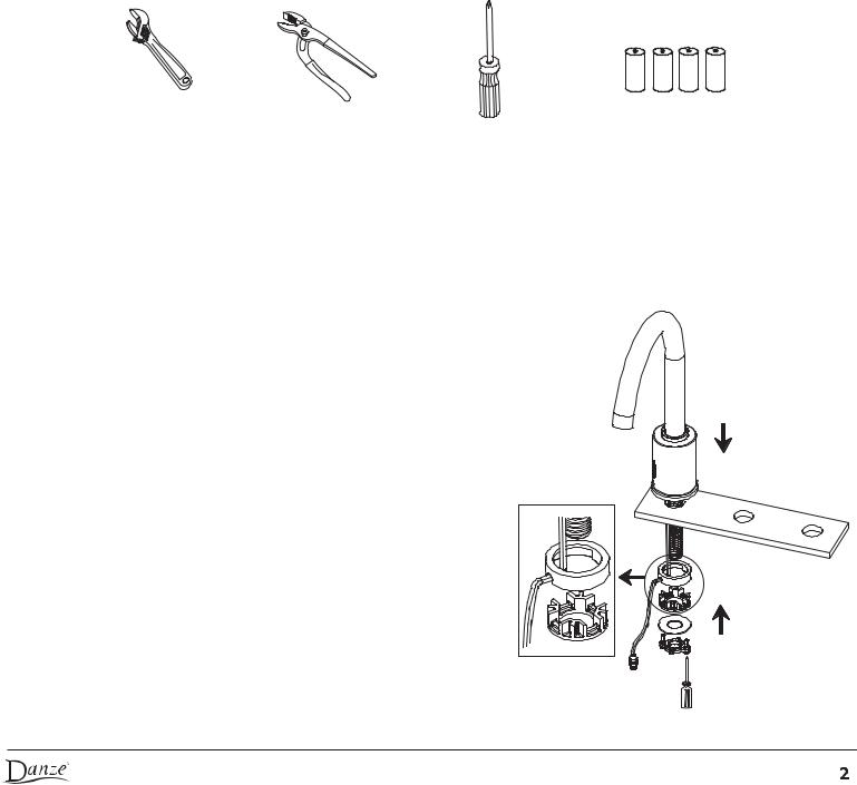
Tools Required
Adjustable wrench |
Channel lock plier |
Philips screwdriver |
C Style 1.5 Volt battery |
Operation Manual
1.INSTALL SPOUT ASSEMBLY:
Place the spout into the hole of sink. The sensor window should be oriented to the
location best suited to the user to activate the faucet while limiting the possibility of accidental activation. For double bowl sinks, often best location is directly over the sink separation; for single bowl sinks, often best orientation is 45 degrees away from the sink. Attach the rubber washer, plastic wire washer, metal washer and brass lock nut to the spout shank. A protective film over the sensor window can be removed after installation is complete.
NOTE: The rubber washer and plastic wire washer are designed to allow passage of the wire. Insert properly to avoid pinching wires. Position carefully the wire washer, slip up the flat washer and screw the lock nut until snug. Verify again for correct wire clearance and tighten nut as required.
© 2009 Danze, Inc. All rights reserved.
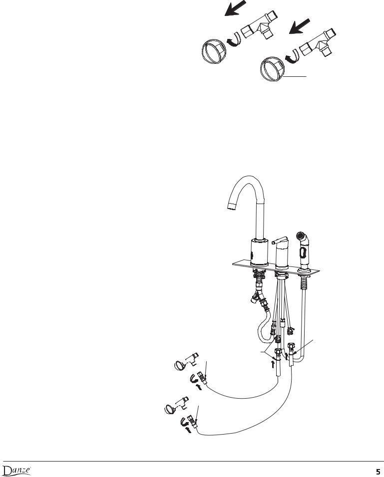
2.
3.
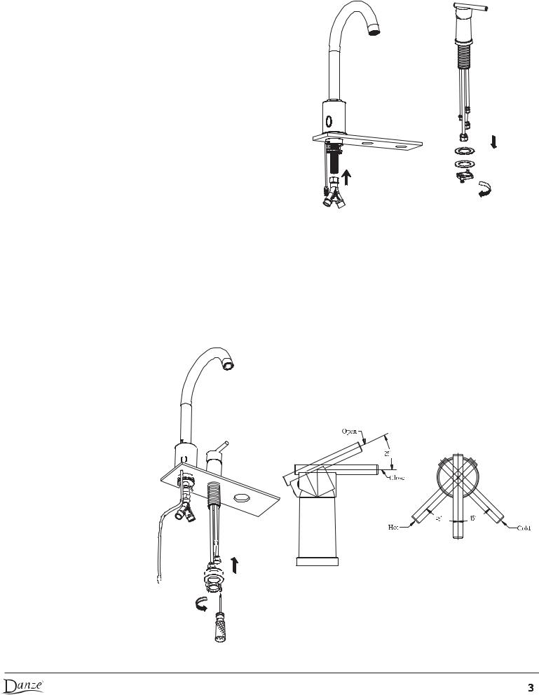
Install the "Y" adapter to the end of spout body shank.
INSTALL MANUAL VALVE ASSEMBLY:
3.1. Remove the hardware assembly from the base of the valve body.
2. 3.1
3.2.Insert the valve body through the mounting hole. Secure the valve to the countertop using the mounting hardware. Before tightening the handle body, BE SURE that the lever handle is correctly centered left to right between the hot and cold positions. A red/blue (hot/cold) self-adhesive decal is included in your parts package; you can place it below the lever on the handle if you choose.
3.2
© 2009 Danze, Inc. All rights reserved.
3.3.Connect the hose adapter (marked ORANGE) to discharge fitting (marked ORANGE) and the other end of hose (marked BROWN) to Y adaptor(Marked BROWN). Tighten carefully.
Copper connections can be spread slightly to facilitate the
attachment and tightening of the hoses.
 Brown marker
A
Discharge to spout (ORANGE)
Orange marker

To vegetable spray (labeled"For Spray Hose")

 Water supply (BLUE)
(the long tube labeled
"For Hot Side")

 B
B


 A
A
B
3.3
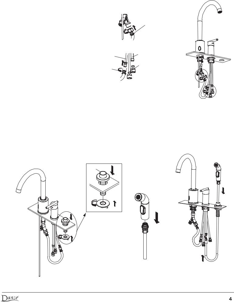
4.INSTALL VEGETABLE SPRAY ASSEMBLY:
4.1.Remove plastic mounting lock nut from spray holder and insert the spray holder from above into the mounting hole. Use lock nut to securely attach to the sink.
4.2.Attach the spray hose to the spray head.
4.3.Insert spray hose through spray holder and install the hose adapter to the brass tube labeled "For Spray Hose". Make sure sprayer hose remains unobstructed and does not become tangled with other hose beneath the sink.
4.1 |
4.2 |
4.3 |
© 2009 Danze, Inc. All rights reserved.
5.CONNECT "T" ADAPTERS TO SUPPLY VALVES:
Install the "T" adapters onto the water supply stop valves from house.
Water supply stop valves from house
5.
6.CONNECT WATER SUPPLY TO MANUAL CONTROL VALVE:
Install water supply hoses marked BLUE to hot and cold valve inlets in the countertop mounted valve. Note: the connection should be "hot to hot" and "cold to cold". Connect the other end of hoses to water supply stop valves marked YELLOW.

 Blue Marker
Blue Marker


 Yellow Marker


 Yellow Marker
6.
© 2009 Danze, Inc. All rights reserved.
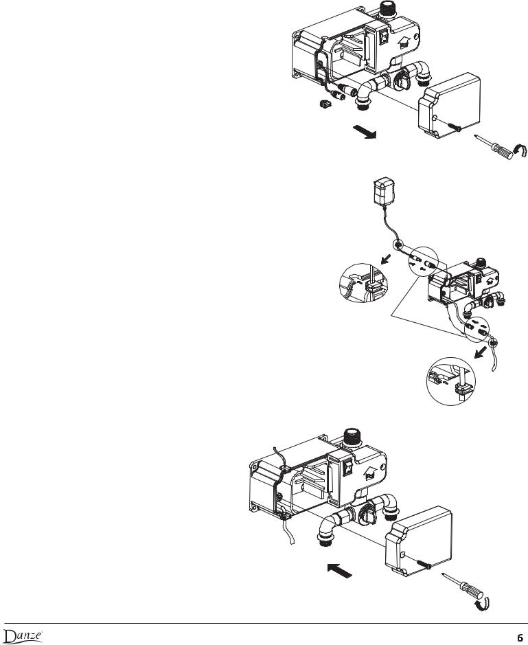
7.INSTALL SENSOR CONTROL BOX UNDER SINK:
Before installing the sensor control box, keep the following in mind: ensure it is accessible so that it is not too difficult to turn it on/off, adjust the temperature and
change the battery. Verify that any shelving garbage can holders mounted on the inside of doors, or other cupboard hardware will not interfere with the unit.
7.1 FOR AC POWERED OPERATION:
a. Remove the cover from sensor control box by using phillips screwdriver. Take the rubber grommet with one hole out of the box. Note: the "ON-OFF" switch should be turned to OFF (O) position during installation.
7.1.a
b. Connect sensor lead from spout to sensor connection in box. Insert sensor
lead wire into the rubber grommet with one hole. Locate grommet between sensor and connection. Reinstall it to the lower slot. Connect power supply wire from AC adapter to power connection in box. Then install rubber grommet onto the upper slot (all connections should be placed inside the box before replacing the lid).
Be sure to place wire joints inside the box before closing.
c. Arrange the wires and connection in the sensor control box and reinstall |
7.1.b |
|
|
the cover. Plug AC adaptor to power supply (110VAC). |
|
7.1.c
© 2009 Danze, Inc. All rights reserved.

7.2 FOR DC POWER OPERATION:
a. Remove the cover from sensor control box by using screwdriver. Take the rubber grommet with one hole out of the box. Note: the "ON-OFF" switch should be turned to OFF(O) position during installation.
b. Connect sensor lead from spout to sensor connection in box. Insert sensor lead wire into the rubber grommet with one hole. Locate grommet between sensor and connection. Reinstall it to the lower slot. Install the grommet without hole to the upper slot.
7.2.a
Be sure to place wire |
|
|
joints inside the box |
Grommet without hole |
|
before closing. |
||
|
7.2.b
c. Install 4 1.5V "C'' sized alkaline batteries to make sure the required battery polarity on battery holder. Place the battery holder into the sensor control box. Arrange wire and connection joint inside box, then reinstall cover.
8.Select location on side wall of cabinet that will let you easily service the battery pack and adjust the temperature of the water. Position the sensor box on wall. Attach sensor control box to wall with mounting screws.
Note: Sensor control box should be mounted as close to front of cabinet as possible for easy valve adjustments and battery service.
7.2.c
Wall 
8
© 2009 Danze, Inc. All rights reserved.
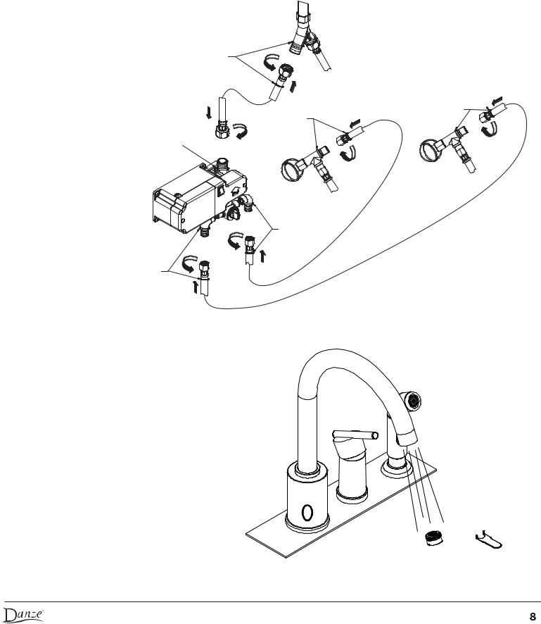
9.CONNECT HOSES TO SENSOR CONTROL BOX: Connect supply hoses (marked green) to inlet fittings (marked green) at mixing valve on control box. Note: the connection should be "hot to hot" and "cold to cold". Connect the spout connection hose to the discharge port of the control box and to the Y adapter (red to red).
Red marker
Green marker
Red marker 
Cold
Green marker
Hot
Green marker
Green marker
Hot
Cold
9
10. After installing faucet, remove aerator and flush the faucet to remove any leftover debris. Reinstall the aerator.
10
© 2009 Danze, Inc. All rights reserved.
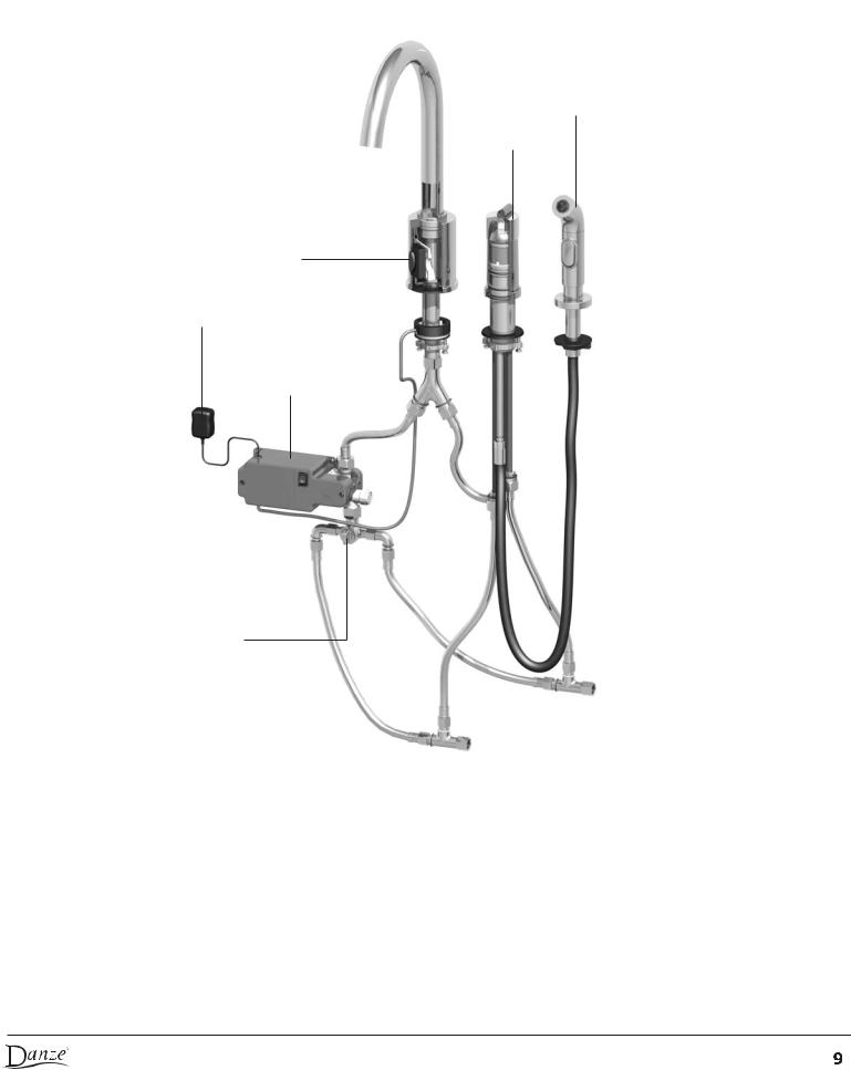
Installation Diagram
Brass Vegetable Spray
Hand Control
Hands Free Sensor
Optional AC
Hands Free
Control Box
Hands Free
Hot/Cold Mixing Valve
Hands Free Operation
1.After the unit has been installed, before turning on the unit, make sure that there is no obstruction in directly in front of the sensor lens. Then turn it on by pressing the ON-OFF switch on the control box to ON (I). Note: do NOT activate the waterflow until the led sensor light turns off ( for 10 seconds or so).
2.For hands-free operation, the waterflow can be turned on by placing a hand (or other object) briefly in front of the electronic sensor (within about 3”). The red indicator LED sensor light will blink and the waterflow will turn on and stay on for a factory-programmed 30 seconds.
3.If the user wishes to stop the waterflow, simply place a hand in front of the sensor a second time. Again, the LED sensor light will blink and the waterflow will turn off.
© 2009 Danze, Inc. All rights reserved.
Setting Temperature For Hands Free Operation
You can set the temperature of the water for hands free operation by adjusting the temperature control knob on the control box. Note: Be sure to have the manual faucet lever turned off or it will interfere with this setting.
How To Change Flow-time Of Hands Free Operation


 Cold
Cold
Hot 


•locate the ON-OFF switch on the control box and switch to OFF (O) for a period of 5 seconds... then switch back to ON (I).
•You can program the flow time during the first 5 seconds after the power is switched on. During this 5 seconds a red light in the sensor window will turn on and stay lit for a 5 second period. To program, place your hand in front of the sensor while the light is on.
•As you keep your hand in front of the sensor the light will begin to blink at one second intervals. Each blink will account for a 5 second automatic run time (e.g. 4 blinks = 20 seconds). The maximum flow time is at 45 seconds or 9 blinks.
Note: beyond 9 blinks the unit will set the maximum flow time (45 seconds).
•After the desired number of blinks, remove the hand, wait a few seconds and the sensor will blink 3 times to confirm the new run time.
•On power-off conditions the last programmed parameters are retained in memory.
Changing Batteries
•When the red light flashes continuously, the batteries need to be changed.
•Remove the sensor control box cover by unscrewing the left hand screw.
•Carefully unplug and remove the battery pack.
•Remove old batteries and install 4 fresh “C” sized batteries (taking care to observe the required battery polarity) into the battery pack.
•Re-insert battery pack into the sensor control box cavity and re-connect plug.
•Re-install sensor control box cover taking care not to pinch wires.
•Turn on faucet by pushing ON-OFF switch to ON (1).
Care + Maintenance
Your new faucet is designed for years of trouble-free performance. Keep it looking new by cleaning it periodically with a soft cloth. Avoid abrasive cleaners, steel wool and harsh chemicals as these will dull the finish and void your warranty.
Hands Free Operation Trouble Shooting Guide
Confirm that the faucet is working properly in manual mode by operating the manual water handle. If the water flow can be properly turned on and off, turn off the manual activation and proceed to check the automatic functions as shown below.
1.An object is within detection range but there is no water flow and the red light is not lit.
•Turn the power off and on using the NO-OFF switch on the sensor control box and confirm result.
•If the red light is still not lit, check the electronic power connections (AC plug in/battery/battery connection).
© 2009 Danze, Inc. All rights reserved.
 Loading...