


|
|
|
|
|
IPP |
|
|
|
|
|
|
|
|
|
|
|
|
|
|
|
|
|
|
|
|
|
|
|
|
|
|
|
|
|
IPP |
|
|||||
Insert / Built-In |
|
|||||
Bay View Insert / Built-In |
|
|||||
|
|
|||||
FPP |
FPP |
Bay View Freestanding |
Freestanding |
Toll Free Technical Support
1 - 866 - 456 -9269
Manufactured by:
To register your purchase
www.dansons.com/support
My local “Pelpro” dealer is:
INSTALL AND USE YOUR HEATER. RESULT IN PROPERTY DAMAGE,
DEATH!
Solid-Fuel-Burning Appliances and
Solid Fuel Burning Appliances in the US.
Contact local building or fire officials about restrictions and installation inspection requirements in your area.

Dear PELPRO Pellet Stove Owner:
CONGRATULATIONS on the purchase of your PELPRO wood pellet appliance! You have selected the finest in residential wood pellet heating technology.
Let us pass on a few "tips" concerning installing your stove and heating with wood pellets.
1.Whether you install your stove yourself or hire a professional installer, a quality installation is a must for the safety of your family and for efficient, satisfactory operation of your stove.
2.Initial Burn Setup of the stove is the most important step to ensure the efficient and satisfactory operation of your appliance for many years to come.
3.Know the quality and characteristics of the pellets you burn. Pellets can vary greatly from company to company, from load to load and occasionally from bag to bag.
4.Be extra diligent in your cleaning program.
5.Remember that most operational dilemmas with a pellet stove are usually traced back to
Improper installation, poor quality pellets and/or a lack of timely cleaning.
With just a minimum of daily care your PELPRO pellet appliance will provide years of clean, efficient, comfortable and environmentally sound heating.
Thank you for selecting a PELPRO wood pellet appliance.
Sincerely,
Canadian Comfort Industries &
Dansons Group Inc.
UPDATES and REGISTRATION
Up to date additions, product information, product registration and warranty extension registration can be found on our website www.dansons.com/support
COPYRIGHT NOTICE
Copyright 2004, Canadian Comfort Industries. All rights reserved.
No part of this manual may be copied, transmitted, transcribed, stored in a retrieval system, in any form or by any means without the expressed written permission of,
Canadian Comfort Industries; 26319 Twp Rd 531, Acheson, AB, Canada T7X 5A3
Canadian Comfort Industries V04 |
2 |
PELPRO OWNERS MANUAL |
Copyright 2004 |
www.pelprostoves.com |
Dansons Group Inc. |

TABLE OF CONTENTS
INTRODUCTION ------------------------------------------------------------------------------------ |
2 |
TABLE OF CONTENTS ---------------------------------------------------------------------------- |
3 |
SAFETY PRECAUTIONS ------------------------------------------------------------------------- |
4,5 |
SPECIFICATIONS --------------------------------------------------------------------------------- |
6 |
AUTOMATIC SAFETY FEATURES -------------------------------------------------------------- |
7 |
INSTALLATION OPTIONS ----------------------------------------------------------------------- |
8 |
INSTALLATION CHECK LIST ------------------------------------------------------------------- |
9 |
EXHAUST SYSTEMS ------------------------------------------------------------------------------ |
10 |
GENERAL ---------------------------------------------------------------------------------------- |
10 |
SIZING --------------------------------------------------------------------------------------------- |
10 |
TERMINATION ---------------------------------------------------------------------------------- |
11 |
CLEARANCES ----------------------------------------------------------------------------------- |
11 |
OUTSIDE AIR ---------------------------------------------------------------------------------------- |
12 |
FREESTANDING INSTALLATION -------------------------------------------------------------- |
13 |
STOVE PLACEMENT --------------------------------------------------------------------------- |
13 |
FLOOR PROTECTION ------------------------------------------------------------------------- |
13 |
CLEARANCES ---------------------------------------------------------------------------------- |
13,14 |
ALCOVE ------------------------------------------------------------------------------------------- |
14 |
THROUGH THE WALL DIRECT INSTALLATION ------------------------------------- |
15 |
VERTICAL INSTALLATIONS ---------------------------------------------------------------- |
16 |
MOBILE HOME INSTALLATION ---------------------------------------------------------------- |
17 |
INSERT / BUILT-IN INSTALLATION |
|
IN A WOOD OR COAL BURNING FIREPLACE ---------------------------------------- |
18,19 |
IN A WALL OR MANTEL ---------------------------------------------------------------------- |
20,21 |
OPERATING YOUR STOVE --------------------------------------------------------------------- |
22 |
HOW YOUR PELPRO STOVE WORKS ------------------------------------------------------ |
22 |
LIGHTING A FIRE ---------------------------------------------------------------------------------- |
23 |
THE ACUTRON CONTROLS -------------------------------------------------------------------- |
24,25 |
SHUTTING THE STOVE OFF ------------------------------------------------------------------- |
25 |
PERFORMANCE ENHANCEMENT TIPS ----------------------------------------------------- |
26 |
ACUTRON WALL THERMOSTAT (OPTIONAL) ------------------------------------------- |
27 |
INITIAL BURN SETUP ----------------------------------------------------------------------------- |
28 |
PELLETS |
|
PELLET QUALITY ------------------------------------------------------------------------------ |
29 |
PELLET CONSUMPTION --------------------------------------------------------------------- |
29 |
FACTORS EFFECTING PELLET FEED RATES --------------------------------------- |
29 |
FINE TUNING THE PELLET FEED RATES ---------------------------------------------- |
29 |
ASH and CLINKERS --------------------------------------------------------------------------- |
30 |
FINES --------------------------------------------------------------------------------------------- |
30 |
PFI PELLET STANDARDS ------------------------------------------------------------------- |
30 |
INSERTING, REMOVING, AND ADJUSTING THE BURN GRATE --------------------- |
31 |
REQUIRED CLEANING --------------------------------------------------------------------------- |
32 |
PERIODIC MAINTENANCE ---------------------------------------------------------------------- |
33-34 |
TROUBLE SHOOTING ---------------------------------------------------------------------------- |
35 |
LIMITED WARRANTY ----------------------------------------------------------------------------- |
36 |
APPENDIX “A” - PELPRO OPTIONS ----------------------------------------------------------- |
37 |
APPENDIX “B” – PELPRO ACCESSORIES ------------------------------------------------- |
38,39 |
SERVICE LOG -------------------------------------------------------------------------------------- |
40 |
Canadian Comfort Industries V04 |
3 |
PELPRO OWNERS MANUAL |
Copyright 2004 |
www.pelprostoves.com |
Dansons Group Inc. |

SAFETY PRECAUTIONS
oDo not operate the heater if you smell smoke coming from the heater. Push the “OFF” Touch pad, monitor your heater, and call your dealer.
oNever use gasoline, gasoline-type lantern fuel, kerosene, charcoal lighter fluid, or similar liquids to start or ’freshen up’ a fire in this heater. Keep all such liquids well away from the heater while it is in use.
o Don’t unplug the heater if you suspect a malfunction. Push the “OFF” Touch pad and inspect the heater.
oDo not operate the heater if the flame becomes dark & sooty or if the firepot overfills with pellets. Push the ”OFF” Touch pad and periodically inspect the heater (see ”Operating Your Stove”).
oNever try to repair or replace any part of the heater unless instructions for consumer are given in this manual. All other work should be done by a trained technician.
o The viewing door and ash pan must be closed and latched during operation.
o Never block free airflow through the open vents of the unit.
oContact your local building officials to obtain a permit and information on any installation restrictions or inspection requirements in your area. Notify your insurance company of this heater as well.
oThe pellet appliance exhaust system works with negative combustion chamber pressure and a slightly positive chimney pressure, therefore the exhaust system must be completely airtight and properly installed. All pellet vent joints must be sealed with HI-TEMP RTV silicone sealant and at least 3 sheet metal screws, to each other as well as to the heater.
oThis unit must be properly installed to prevent the possibility of a house fire. The instructions must be strictly adhered to. Do not use makeshift methods, which may compromise the installation.
oYour heater requires periodic maintenance and cleaning (see ”Operating Your Stove”). Failure to maintain your heater may lead to smoke spillage in your home.
oAllow the heater to cool before carrying out any maintenance or cleaning. Ashes must be disposed in a metal container with a tight fitting lid. The closed container of ashes should be placed on a non-combustible surface or on the ground, well away from all combustible materials, pending final disposal.
oThis heater is designed and approved for pelletized wood fuel only. Any other type of fuel burned in this heater will void the warranty and safety listing.
oThe heater will not operate during a power outage. If a power outage does occur, check the heater for smoke spillage and open a window if any smoke spills into the room.
o Keep foreign objects out of the hopper.
Canadian Comfort Industries V04 |
4 |
PELPRO OWNERS MANUAL |
Copyright 2004 |
www.pelprostoves.com |
Dansons Group Inc. |

SAFETY PRECAUTIONS . . . Continued
oDisconnect the power cord before performing any maintenance. NOTE: Touching the OFF touch pad does not disconnect all power to the heater.
oDo not throw this manual away. This manual has important operating and maintenance instructions that you will need at a later time. Always follow the instructions in this manual.
oDo not place clothing or other flammable items on or near the heater. Because this heater can be controlled by a thermostat there is a possibility of the heater turning on and igniting any items placed on or near it.
oThis heater must be connected to a standard 110 - 120V., 60 Hz grounded electrical outlet. Do not use an adapter plug or sever the grounding plug. Do not route the electrical cord underneath,
in front of, or over the heater.
oIt is recommended to connect the heater to a standard 110 – 120V ground surge protected unit or surge protected electrical outlet..
oWhen installed in a mobile home, the heater must be bolted to the floor, have outside air, and MUST NOT BE INSTALLED IN THE BEDROOM (Per H.U.D. requirements). Check with local building officials.
o Educate all children on the dangers of a high-temperature heater.
o Young children should be supervised when they are in the same room as the heater.
oCaution: NEVER PUT FINGERS NEAR AUGER. Pellet fuel is fed to the burn pot by a screw auger that is driven by a high torque motor. The auger can start and stop automatically anytime while the heater is operating.
o Do not connect this appliance directly to air ducts or any air distribution system. This will void your warranty.
oDo not burn with insufficient combustion air. A periodic check is recommended to ensure proper combustion air is admitted to the combustion chamber. Setting the proper combustion air is achieved by adjusting the slide damper located on the right hand side of the appliance.
o It is advisable to clean the exhaust vent bi-annually or every two tons of pellets.
oSoot or creosote may accumulate when the stove is operated under incorrect conditions such as an extremely rich burn (black tipped, lazy orange flames).
Note: Canadian Comfort Industries grants no warranty, implied or stated, for the installation or maintenance of your heater, and assumes no responsibility of any consequential damage(s).
Canadian Comfort Industries V04 |
5 |
PELPRO OWNERS MANUAL |
Copyright 2004 |
www.pelprostoves.com |
Dansons Group Inc. |
SPECIFICATIONS
HEATING SPECIFICATIONS
Approx. Heating capacity (sq. feet) * |
800 – 2,000 |
|
|
|
Approx. Fuel burn rate per hour ** |
1.5 – 5 lbs |
|
|
|
Hopper Capacity - Traditional Stove / Insert |
40 lbs |
Approx. Burn time at lowest setting |
27 hrs |
|
Hopper Capacity – Bay View |
Free Standing |
60 lbs |
Approx. Burn time at lowest setting |
48 hrs |
Hopper Capacity – Bay View |
Insert / Built-In |
40-60 lbs |
Approx. Burn time at lowest setting |
27-48 |
*Heating capacity will vary depending on floor plan layout of your home, degree of insulation, and the outside temperature. Fuel size, quality, density and moisture level will also have an effect.
**Pellet size may effect the actual rate of fuel feed and burn times. Fuel feed rates may vary by as much as 20%. Use PFI listed fuel for best results.
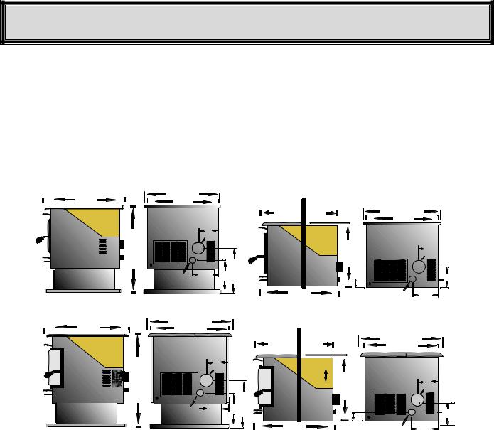
DIMENSIONS
24” |
28 3/4” |
24 3/4” |
|
|
24” |
|
|
|
6 1/2” |
|
|
Exhaust |
|
+ |
|
|
+ |
|
17 1/4” |
|
|
|
Air Inlet |
8 1/4” |
12 3/4” |
Traditional Freestanding
Shroud 1” |
|
|
|
12 1/4” |
10 3/4” |
24 3/4” |
|
|
|
24” |
|
|
|
|
6 1/2” |
|
18 3/4” |
|
Exhaust |
|
3 ½” |
+ |
|
|
+ |
7 3/4” |
|
|
24” |
Air Inlet |
8 1/4” |
|
|
|
|
Traditional Insert / Built-In
24” |
26” |
|
|
Shroud 1” |
|
|
|
|
|
25” |
|
|
|
|
|
|
|||
|
|
|
|
|
|
|
|
|
|
|
|
|
|
12 1/4” |
10 3/4” |
|
|
26” |
|
|
|
|
|
|
|
24” |
|
||
|
|
|
|
|
|
|
|
|
|
|
30” |
|
7” |
|
Adjustable |
|
|
|
|
|
|
Exhaust |
|
|
|
|
|||
|
|
+ |
|
Hopper |
19” |
|
|
6 ½” |
|
|
|
|
|
|
|
||||
|
|
|
|
- |
|
|
Exhaust |
||
|
+ |
|
|
|
|
|
|||
|
|
17” |
|
23” |
|
+ |
|||
|
|
|
|
|
|
|
|||
|
|
|
8 1/4” |
12 3/4” |
|
|
3 ½” |
||
|
Air Inlet |
|
|
|
+ |
7 3/4” |
|||
|
|
|
|
|
|
||||
|
|
|
|
24” |
|
|
|
Air Inlet |
8 1/4” |
|
|
|
|
|
|
|
|
|
|
Bay View Freestanding Bay View Insert / Built-In
ELECTRICAL SPECIFICATIONS
Electrical Rating |
= |
110-120 Volts 60 HZ 2.0 Amps |
Watts (operational) |
= |
175 (approximately) |
Watts (optional igniter) |
= |
475 (approximately) |
A voltage surge protector or ground fault outlet is required for this unit.
EPA COMPLIANCE
This heater is exempt from EPA Phase II requirements, but has been tested for emissions using EPA test methods by Warnock Hersey , US.
FUEL CONSIDERATIONS
Your Pelpro pellet appliance, is designed to burn pellets that comply with Association of Pellet Fuel Industries standards. (Minimum of 40lbs density per cubic ft, ¼ to 5/16’ diameter length no greater than 1.5”, not less than 8,200 BTU’s/lb, moisture under 8% by weight, ash under 1% by weight, and salt under 300 parts per million) Pellets that are soft, contain excessive amounts of loose sawdust, have been or are wet, produce clinkers and/or heavy ash will result in reduced performance and may actually cause the fire to go out.
Canadian Comfort Industries V04 |
6 |
PELPRO OWNERS MANUAL |
Copyright 2004 |
www.pelprostoves.com |
Dansons Group Inc. |
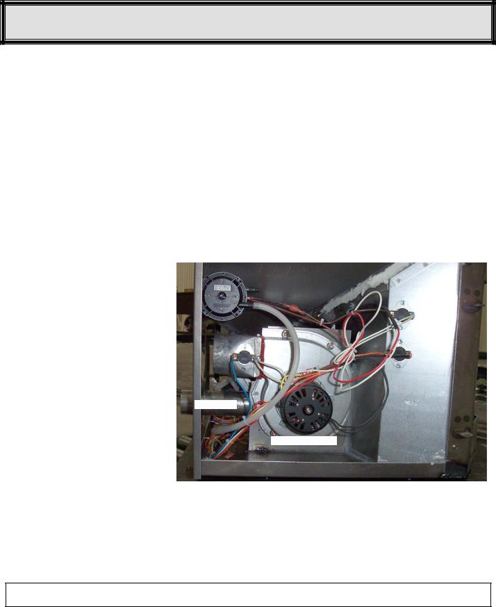
AUTOMATIC SAFETY FEATURES
L250 HIGH LIMIT SWITCH
Your pellet appliance has a high temperature limit switch installed. If the temperature at the back of the firebox reaches approximately 250deg F., the switch will shut off the electricity going to the Vacuum Switch and to the Auger Motor. The auger will automatically stop, and the appliance will shut down when the exhaust temperature cools (120deg F). If this happens call your dealer or Dansons Customer Service (1-866-456-9269).
IT IS IMPORTANT TO FIND THE REASON WHY THE UNIT OVERHEATED.
L120 LOW LIMIT SWITCH
This limit switch is mounted on the exhaust blower housing and has 2 main functions.
1.Should the fire happen to go out, for any reason, this limit switch will shut the stove off when the exhaust temperature drops below 120deg F.
2.Upon starting the appliance, the AcuTron control board has a 15 minute “Lighting Mode”, if the stove exhaust does not reach 120deg F in that 15 minutes the stove will shut off. As soon as the stove exhaust does reach 120deg F, the limit switch opens and the AcuTron enters a 5 minute “Safety Delay” mode.
F140 FAN LIMIT SWITCH
Your pellet appliance has a convection fan control limit switch. The room air fan's (F140) temperature limit snap switch automatically sets the fan on high when your stove is producing heat faster than the fan is carrying it into the room. This may occur when the heat control lever is set at [3 or 4] and the FAN SPEED is set to a very low or off setting. After the fan runs at this
automatic high setting a few minutes, |
|
|
|
|
|
|
|
|
Vacuum Switch |
||||||
it may cycle back to its lower setting |
|
|
|
|
|
|
|
and may continue to cycle between |
|
|
|
|
|
|
|
|
|
|
|
|
High Limit L250 |
||
[HIGH] and your selected setting. |
|
|
|
|
|
||
|
|
|
|
|
|
|
|
The circulation (room air) fan cycling |
|
|
|
|
|
|
|
from high to low is a normal condition |
|
|
|
|
|
|
|
as well as a safety feature of your |
|
|
|
|
|
|
|
|
|
Low Limit L120 |
|
|
|
||
appliance. To compensate for the fan |
|
|
|
|
|
||
|
|
|
|
|
|
|
|
cycling, adjust the FAN SPEED to a |
|
|
|||||
Exhaust |
|||||||
higher setting. |
|
|
|
|
|
|
|
|
|
|
|
|
Fan Limit F140 |
||
VACUUM SWITCH
This safety device (mounted on the back panel pillar) detects vacuum in the exhaust system, firebox, and air intake. If the exhaust blower fails, the vent pipe becomes plugged, the viewing door is open, or if you are out of pellets, this switch will sense that there is no airflow and will stop the auger from continuing to feed pellets.
Air Intake
Combustion Fan
AcuTron Wiring Harness
If the power does go out, the pellet appliance will stop running. When the power comes back on, the stove will not restart if the switch is in the manual mode. If the exhaust temperature is above 120deg F or the switch is in the manual position, the stove will start to feed pellets again and may re-light itself.
NOTE: If power outages are a concern you may wish to purchase a battery back-up system. It must state “For Igniter Equipped Appliance” and be a minimum of 750 watts.
For further information contact your local Specialty Retailer, Certified HVAC Service Depot, or Dansons Group Inc. Customer Service Department at 1-866-456-9269.
Canadian Comfort Industries V04 |
7 |
PELPRO OWNERS MANUAL |
Copyright 2004 |
www.pelprostoves.com |
Dansons Group Inc. |
INSTALLATION OPTIONS
READ THIS ENTIRE MANUAL BEFORE YOU INSTALL AND USE YOUR PELPRO HEATER. FAILURE TO FOLLOW INSTRUCTIONS MAY RESULT IN PROPERTY DAMAGE, BODILY INJURY OR EVEN DEATH!
(See specific Installation details for clearances and other installation requirements)
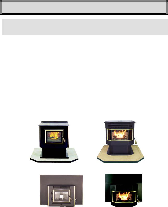
The two PELPRO models are the: “FPP” Freestanding: a Traditional styled stove (figure 1), and a Bay View style(figure 2); and the “IPP” Fireplace Insert / Built-In: a Traditional style (figure 3), and a Bay View style (figure 4). Both models come with either black painted or brass trimmed doors.
All models may be installed to code in both conventional and mobile homes.
INSTALLATION OPTIONS INCLUDE:
1.A FREESTANDING STOVE: Set on a pedestal and placed on a non-combustible floor pad. (figure 1 &2)
2.An ALCOVE: Set on a pedestal and placed on a non-combustible floor pad in compliance with clearance requirements for an installation in an alcove. (figure 1 & 2)
3.A HEARTH STOVE: When installed with or without a pedestal on a non-combustible hearth of a masonry or factory built wood or coal burning fireplace. (figure 1 & 2)
4.A FIREPLACE INSERT: When installed, with a shroud, in a masonry or a factory built, wood or coal burning fireplace. (figure 3 & 4)
5.A BUILT-IN INSERT: When installed on a non-combustible pad, in a wall or custom built mantel and where adequate airflow around the stove is provided. (figure 3 & 4)
FPP |
FPP |
Freestanding |
Bay View Freestanding |
Figure 1 |
Figure 2 |
IPP |
IPP |
Insert / Built-In |
Bay View Insert / Built-In |
|
Figure 4 |
Figure 3
Canadian Comfort Industries V04 |
8 |
PELPRO OWNERS MANUAL |
Copyright 2004 |
www.pelprostoves.com |
Dansons Group Inc. |
INSTALLATION CHECK LIST
Unless you are knowledgeable and experienced in stove installation, we recommend your PELPRO stove receive a Pre-delivery Check and be installed by your local Specialty Retailer or Certified HVAC Service Depot.
COMPLETE THIS CHECK LIST PRIOR TO LIGHTING YOUR FIRST FIRE:
_____ |
Carefully read this "Owner's Manual”. SAVE THIS MANUAL. |
_____ |
Obtain final inspection and approval by local building officials. |
_____ |
Carefully clean all marks off the brass parts before the first fire is lit. Use a soft cloth and a gentle type |
|
cleaner. Caution: Never use an abrasive cleaner on any part of your stove. |
_____ |
Polish the hopper to remove the oil type coating used in manufacturing. |
_____ |
Have your local Dealer demonstrate all the operational, cleaning and maintenance steps necessary |
|
for your stove. |
_____ Sign and keep a copy of the Pre-delivery Check List supplied by your Authorized Pelpro Dealer,
|
“Dansons Certified Installer”, found inside our appliance or available online. |
|
Register online at www.dansons.com/support for Extended Warranty. |
______ |
Register your purchase online at www.dansons.com/support. |
_____ |
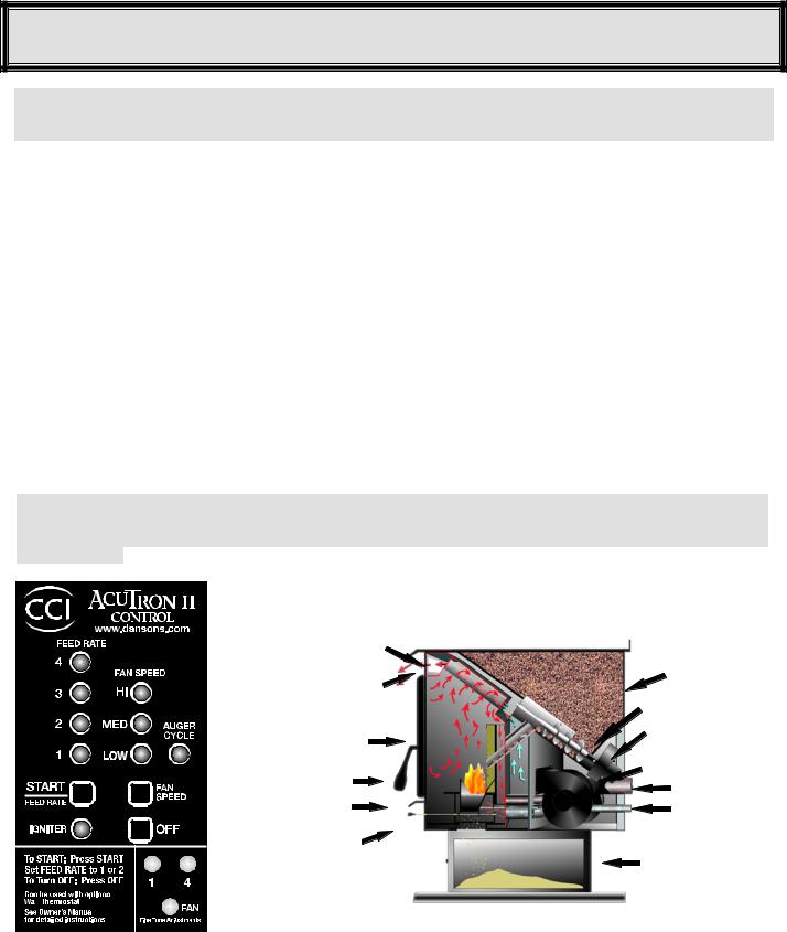
Fill the hopper with quality pellets to prime the unit; Using the CCI “AcuTron”, (figure 5), PUSH the |
|
FEED RATE Touch Pad and this will start the auger and the combustion fan. |
NOTE: Do not attempt to light a fire at this time. Leave the START / FEED RATE [ON] for 2 to 5 minutes until pellets start dropping into the burn grate. Then touch the OFF pad to turn off system . The auger is now primed to deliver fuel to the burn grate (figure 6). Then light the stove according to the directions outlined in "LIGHTING YOUR STOVE",
Heat Tubes |
Hopper |
|
|
||
Tube Scraper |
Auger |
|
|
||
Window |
Auger Motor |
|
|
||
Burn Grate |
Fan Motors |
|
Exhaust |
||
Burn Pot |
||
Air Intake |
||
|
||
E Z Clean |
Ash Pan |
|
Grate |
|
|
|
|
|
|
|
|
|
|
|
|
|
|
|
|
|
|
|
|
|
|
|
|
|
|
|
|
|
|
|
|
|
|
|
|
|
|
|
|
|
|
|
|
|
|
|
|
|
|
|
|
|
|
|
|
|
|
|
CCI –“AcuTron Board” |
|
Cutaway View |
||||
|
|
|
|
|
||||||
|
|
|
|
|
||||||
|
|
|
|
|
|
|
|
Figure 3 |
|
Figure 4 |
Canadian Comfort Industries V04 |
9 |
PELPRO OWNERS MANUAL |
||||||||
Copyright 2004 |
www.pelprostoves.com |
Dansons Group Inc. |
||||||||
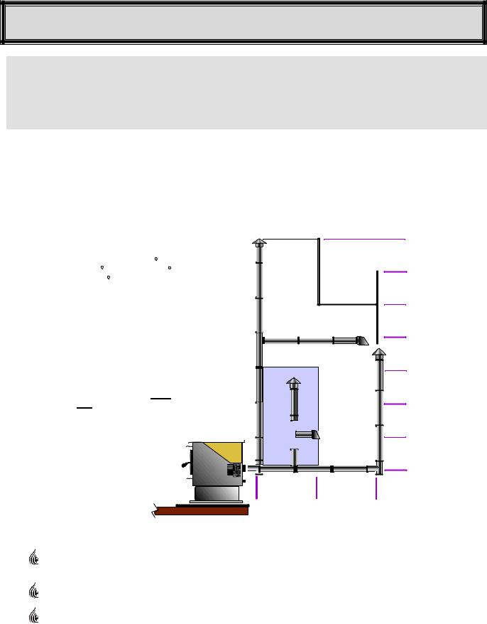
EXHAUST SYSTEMS (GENERAL)
PELLET VENT MUST MAINTAIN A MINIMUM 3” CLEARANCE TO ANY COMBUSTIBLE
(INSTALL VENT AT CLEARANCES SPECIFIED BY THE VENT MANUFACTURER).
DO NOT CONNECT THE PELLET VENT TO A VENT SERVING ANY OTHER APPLIANCE
OR STOVE.
DO NOT INSTALL A FLUE DAMPER IN THE EXHAUST VENTING SYSTEM OF THIS UNIT.
PELLET VENT TYPE:
Must be an approved 3” or 4” Diameter Type ”PL” vent, vented to the outside (fig. 7) or connect the vent to a factory built type “A” chimney using an adaptor; and/or “All Fuel” Stainless Steel chimney liner for masonry fireplace installations (fig. 8) . Use 4” dia. vent if vent or liner height is over 15’ or if installation is over 4,000’ above sea level.
MAXIMUM VENTING SIZE:
Maximum venting height is 33’. Maximum horizontal offset is 10’. Use no more than 180 of elbows (two 90 elbows, or two 45 elbows & one 90 elbow, etc), plus termination.
Vent must have a support bracket every 5’ when on the exterior wall.
If appliance is installed above 4,000’ elevation, always use 4” diameter venting.
Vent height and run must not exceed the distance shown in the un-shaded region of chart.
To achieve optimum performance, keep vent runs as short as possible. Especially on horizontal installations.
33’
30’
25’
Use 4” Diameter “PL” Vent If venting outside of shaded area.
|
20’ |
Use 3” or 4” Diameter |
|
“PL” Vent, if venting in |
|
shaded area. |
15’ |
10’
5’
0’
0’ |
5’ |
10’ |
VENT INSTALLATION:
Termination must exhaust above the air inlet elevation, and parallel or above the exhaust output of the pellet appliance. It is recommended that at least 3’ of vertical pipe be installed to create some natural draft. This is to help prevent the possibility of smoke or odor during the appliance shut down.
Horizontal sections must have a ¼” rise every 12” of travel after 3’ long.
Pellet Vent connections must be sealed with HI-Temp RTV Silicone and screwed together with at least 3 x 3/8” long stainless steel screws. Seal each vent section by injecting a liberal amount of HITEMP RTV silicone sealant into the gap.
Canadian Comfort Industries V04 |
10 |
PELPRO OWNERS MANUAL |
Copyright 2004 |
www.pelprostoves.com |
Dansons Group Inc. |
EXHAUST SYSTEMS . . . Continued
PELLET VENT TERMINATION: (Figures 7 & 8)
Termination must be a minimum of 6” above the chimney (B) (note: the chimney must meet local codes for height above the roof or other obstructions)
Must have an approved cap (to prevent water from entering) or a 45* elbow downturn
If the termination is located on a windy side of house, an approved house shield is recommended to
prevent soot from accumulating on the side of the house. |
B |
|
Must not be located where snow or other materials will plug it. |
||
Must have a “Metal Seal Plate” or “Wall Thimble” at point (A) |
||
|
A |
A |
A |
F |
|
4 |
12” |
G |
Figure 7 |
|
Figure 8 |
VENT TERMINATION CLEARANCES:
•Horizontal terminations must protrude 12” from the wall, vertical terminations 24”
x
3’
2’
10’
Figure 9
AMinimum 4’ clearance below or beside any door or window which opens.
BMinimum 1’ clearance above any door or window that opens.
CMinimum 3’ clearance from any adjacent building.
DMinimum 7’ clearance above any grade when adjacent to public walkways.
NOTE: Vent may not terminate in covered walkway or breezeway.
EMinimum 2’ clearance above any grass, plants, or other combustible material.
FMinimum 3’ clearance from any forced air intake of any other appliance.
GMinimum 2’ clearance below eves or overhang.
HMinimum 1’ clearance horizontally from combustible wall.
X |
Must be a minimum of 36” above the roof and 24” above the highest point of the roof within 10’. |
||
Canadian Comfort Industries V04 |
11 |
PELPRO OWNERS MANUAL |
|
Copyright 2004 |
www.pelprostoves.com |
Dansons Group Inc. |
|
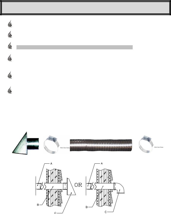
OUTSIDE AIR
Outside air is REQUIRED ON ALL MOBILE HOME INSTALLATIONS.
Outside air is strongly recommended for all other installations. Failure to install intake air may result in improper combustion as well as the unit smoking during power failures.
Metal pipe, ONLY, either solid or flexible, must be used in all outside air installations.(B)
NOTE: Non-metallic material MUST NOT BE USED for outside air installations.
A wind shield, (C), over the termination of the outside air pipe or a 90 degree elbow or bend directed away from the prevailing winds MUST be used when an outside air pipe is installed through the side of a building. Keep the outside air pipe termination at least 1 foot away from the exhaust system termination.
When outside air is taken from an existing chimney the exhaust system must not terminate in the same chimney.
The outside air pipe on your stove is 2" OD. The outside air connecting pipe must be at least 2" ID The outside air connecting pipe must be as short and free of elbows as possible, and must fit over, (A), not inside, the outside air pipe on your stove.
Through The Wall Kits Include:
3 FOOT PACKAGE – PART# ACFAKT3 |
10 FOOT PACKAGE – PART# ACFAKT10 |
||
1 |
– 2” Galvanized Hood c/w screen |
1 |
– 2” Galvanized Hood c/w screen |
1 |
– 2” Aluminum Flex Duct – |
1 |
– 2” Aluminum Flex Duct – |
|
compressed 15” length, extends to 30” – 36” |
|
compressed 4’ length, extends to 120” |
2 |
– 2” Worm Gear Clamps |
2 |
– 2” Worm Gear Clamps |
NOTE: Available from your local Authorized Dealer or Dansons Group Inc. 1-877-303-3134
Figure 9
Canadian Comfort Industries V04 |
12 |
PELPRO OWNERS MANUAL |
Copyright 2004 |
www.pelprostoves.com |
Dansons Group Inc. |
 Loading...