


IPP
Bay View Insert / Built-In
IPP
Insert / Built-In
FPP
Bay View Freestanding
Toll Free Technical Support
1 - 866 - 456 -9269
Manufactured by:
FPP
Freestanding
My local “Pelpro” dealer is:
To register your purchase
www.dansons.com/support
READ THIS ENTIRE MANUAL BEFORE YOU INSTALL AND USE YOUR HEATER.
FAILURE TO FOLLOW INSTRUCTIONS MAY RESULT IN PROPERTY DAMAGE,
BODILY INJURY OR EVEN DEATH!
Installation shall conform to CAN/CSA B365 Installation Code for Solid-Fuel-Burning Appliances and
Equipment in Canada and NFPA 211 Chimney, Fireplaces, Vents and Solid Fuel Burning Appliances in the US
Contact local building or fire officials about restrictions and installation inspection requirements in your area.
.

Dear PELPRO Pellet Stove Owner:
CONGRATULATIONS on the purchase of your PELPRO wood pellet appliance! You have selected the finest in
residential wood pellet heating technology.
Let us pass on a few "tips" concerning installing your stove and heating with wood pellets.
1. Whether you install your stove yourself or hire a professional installer, a quality installation
is a must for the safety of your family and for efficient, satisfactory operation of your stove.
2. Initial Burn Setup of the stove is the most important step to ensure the efficient and satisfactory
operation of your appliance for many years to come.
3. Know the quality and characteristics of the pellets you burn. Pellets can vary greatly from
company to company, from load to load and occasionally from bag to bag.
4. Be extra diligent in your cleaning program.
5. Remember that most operational dilemmas with a pellet stove are usually traced back to
Improper installation, poor quality pellets and/or a lack of timely cleaning.
With just a minimum of daily care your PELPRO pellet appliance will provide years of clean, efficient, comfortable
and environmentally sound heating.
Thank you for selecting a PELPRO wood pellet appliance.
Sincerely,
Canadian Comfort Industries &
Dansons Group Inc.
UPDATES and REGISTRATION
Up to date additions, product information, product registration and warranty extension registration can be found on
our website www.dansons.com/support
COPYRIGHT NOTICE
Copyright 2004, Canadian Comfort Industries. All rights reserved.
No part of this manual may be copied, transmitted, transcribed, stored in a retrieval system, in any form or by any
means without the expressed written permission of,
Canadian Comfort Industries; 26319 Twp Rd 531, Acheson, AB, Canada T7X 5A3
Canadian Comfort Industries V04 2 PELPRO OWNERS MANUAL
Copyright 2004
www.pelprostoves.com Dansons Group Inc.
TABLE OF CONTENTS
INTRODUCTION -----------------------------------------------------------------------------------TABLE OF CONTENTS ---------------------------------------------------------------------------SAFETY PRECAUTIONS ------------------------------------------------------------------------SPECIFICATIONS --------------------------------------------------------------------------------AUTOMATIC SAFETY FEATURES -------------------------------------------------------------INSTALLATION OPTIONS ----------------------------------------------------------------------INSTALLATION CHECK LIST ------------------------------------------------------------------EXHAUST SYSTEMS ----------------------------------------------------------------------------- GENERAL --------------------------------------------------------------------------------------- SIZING -------------------------------------------------------------------------------------------- TERMINATION --------------------------------------------------------------------------------- CLEARANCES ----------------------------------------------------------------------------------OUTSIDE AIR ---------------------------------------------------------------------------------------FREESTANDING INSTALLATION ------------------------------------------------------------- STOVE PLACEMENT -------------------------------------------------------------------------- FLOOR PROTECTION ------------------------------------------------------------------------ CLEARANCES --------------------------------------------------------------------------------- ALCOVE -------------------------------------------------------------------------------------------
THROUGH THE WALL DIRECT INSTALLATION ------------------------------------ VERTICAL INSTALLATIONS ---------------------------------------------------------------MOBILE HOME INSTALLATION ----------------------------------------------------------------
INSERT / BUILT-IN INSTALLATION
IN A WOOD OR COAL BURNING FIREPLACE --------------------------------------- IN A WALL OR MANTEL ---------------------------------------------------------------------OPERATING YOUR STOVE --------------------------------------------------------------------HOW YOUR PELPRO STOVE WORKS -----------------------------------------------------LIGHTING A FIRE ---------------------------------------------------------------------------------THE ACUTRON CONTROLS -------------------------------------------------------------------SHUTTING THE STOVE OFF ------------------------------------------------------------------PERFORMANCE ENHANCEMENT TIPS ----------------------------------------------------ACUTRON WALL THERMOSTAT (OPTIONAL) ------------------------------------------INITIAL BURN SETUP ----------------------------------------------------------------------------PELLETS
PELLET QUALITY ----------------------------------------------------------------------------- PELLET CONSUMPTION -------------------------------------------------------------------- FACTORS EFFECTING PELLET FEED RATES -------------------------------------- FINE TUNING THE PELLET FEED RATES --------------------------------------------- ASH and CLINKERS -------------------------------------------------------------------------- FINES -------------------------------------------------------------------------------------------- PFI PELLET STANDARDS ------------------------------------------------------------------INSERTING, REMOVING, AND ADJUSTING THE BURN GRATE --------------------REQUIRED CLEANING --------------------------------------------------------------------------PERIODIC MAINTENANCE ---------------------------------------------------------------------TROUBLE SHOOTING ---------------------------------------------------------------------------LIMITED WARRANTY ----------------------------------------------------------------------------APPENDIX “A” - PELPRO OPTIONS ----------------------------------------------------------APPENDIX “B” – PELPRO ACCESSORIES ------------------------------------------------SERVICE LOG --------------------------------------------------------------------------------------
2
3
4,5
6
7
8
9
10
10
10
11
11
12
13
13
13
13,14
14
15
16
17
18,19
20,21
22
22
23
24,25
25
26
27
28
29
29
29
29
30
30
30
31
32
33-34
35
36
37
38,39
40
adian Comfort Industries V04 3 PELPRO OWNERS MANUAL
Can
Copyright 2004
www.pelprostoves.com Dansons Group Inc.

SAFETY PRECAUTIONS
o Do not operate the heater if you smell smoke coming from the heater. Push the “OFF” Touch pad,
monitor your heater, and call your dealer.
o Never use gasoline, gasoline-type lantern fuel, kerosene, charcoal lighter fluid, or similar liquids to start or
’freshen up’ a fire in this heater. Keep all such liquids well away from the heater while it is in use.
o Don’t unplug the heater if you suspect a malfunction. Push the “OFF” Touch pad and inspect the heater.
o Do not operate the heater if the flame becomes dark & sooty or if the firepot overfills with pellets. Push the
”OFF” Touch pad and periodically inspect the heater (see ”Operating Your Stove”).
o Never try to repair or replace any part of the heater unless instructions for consumer are given in this manual.
All other work should be done by a trained technician.
o The viewing door and ash pan must be closed and latched during operation.
o Never block free airflow through the open vents of the unit.
o Contact your local building officials to obtain a permit and information on any installation restrictions or
inspection requirements in your area. Notify your insurance company of this heater as well.
o The pellet appliance exhaust system works with negative combustion chamber pressure and a slightly
positive chimney pressure, therefore the exhaust system must be completely airtight and properly installed.
All pellet vent joints must be sealed with HI-TEMP RTV silicone sealant and at least 3 sheet metal screws, to
each other as well as to the heater.
o This unit must be properly installed to prevent the possibility of a house fire. The instructions must be strictly
adhered to. Do not use makeshift methods, which may compromise the installation.
o Your heater requires periodic maintenance and cleaning (see ”Operating Your Stove”). Failure to maintain
your heater may lead to smoke spillage in your home.
o Allow the heater to cool before carrying out any maintenance or cleaning. Ashes must be disposed in a metal
container with a tight fitting lid. The closed container of ashes should be placed on a non-combustible surface
or on the ground, well away from all combustible materials, pending final disposal.
o This heater is designed and approved for pelletized wood fuel only. Any other type of fuel burned in this
heater will void the warranty and safety listing.
o The heater will not operate during a power outage. If a power outage does occur, check the heater for smoke
spillage and open a window if any smoke spills into the room.
o Keep foreign objects out of the hopper.
adian Comfort Industries V04 4 PELPRO OWNERS MANUAL
Can
Copyright 2004
www.pelprostoves.com Dansons Group Inc.

SAFETY PRECAUTIONS . . . Continued
o Disconnect the power cord before performing any maintenance. NOTE: Touching the OFF touch pad does not
disconnect all power to the heater.
o Do not throw this manual away. This manual has important operating and maintenance
instructions that you will need at a later time. Always follow the instructions in this manual.
o Do not place clothing or other flammable items on or near the heater. Because this heater can
be controlled by a thermostat there is a possibility of the heater turning on and igniting any
items placed on or near it.
o This heater must be connected to a standard 110 - 120V., 60 Hz grounded electrical outlet. Do not
use an adapter plug or sever the grounding plug. Do not route the electrical cord underneath,
in front of, or over the heater.
o It is recommended to connect the heater to a standard 110 – 120V ground surge protected unit or
surge protected electrical outlet..
o When installed in a mobile home, the heater must be bolted to the floor, have outside air, and MUST
NOT BE INSTALLED IN THE BEDROOM (Per H.U.D. requirements). Check with local building officials.
o Educate all children on the dangers of a high-temperature heater.
o Young children should be supervised when they are in the same room as the heater.
o Caution: NEVER PUT FINGERS NEAR AUGER. Pellet fuel is fed to the burn pot by a screw auger that is
driven by a high torque motor. The auger can start and stop automatically anytime while the heater is
operating.
o Do not connect this appliance directly to air ducts or any air distribution system. This will void your warranty.
o Do not burn with insufficient combustion air. A periodic check is recommended to ensure proper combustion
air is admitted to the combustion chamber. Setting the proper combustion air is achieved by adjusting the
slide damper located on the right hand side of the appliance.
o It is advisable to clean the exhaust vent bi-annually or every two tons of pellets.
o Soot or creosote may accumulate when the stove is operated under incorrect conditions such as an extremely
rich burn (black tipped, lazy orange flames).
Note: Canadian Comfort Industries grants no warranty, implied or stated, for the installation or
maintenance of your heater, and assumes no responsibility of any consequential damage(s).
adian Comfort Industries V04 5 PELPRO OWNERS MANUAL
Can
Copyright 2004
www.pelprostoves.com Dansons Group Inc.
”
”
”
SPECIFICATIONS
HEATING SPECIFICATIONS
Approx. Heating capacity (sq. feet) * 800 – 2,000
Approx. Fuel burn rate per hour ** 1.5 – 5 lbs
Hopper Capacity - Traditional Stove / Insert 40 lbs Approx. Burn time at lowest setting 27 hrs
Hopper Capacity – Bay View Free Standing 60 lbs Approx. Burn time at lowest setting 48 hrs
Hopper Capacity – Bay View Insert / Built-In 40-60 lbs Approx. Burn time at lowest setting 27-48
* Heating capacity will vary depending on floor plan layout of your home, degree of insulation, and the outside
temperature. Fuel size, quality, density and moisture level will also have an effect.
** Pellet size may effect the actual rate of fuel feed and burn times. Fuel feed rates may vary by as much as 20%. Use
PFI listed fuel for best results.
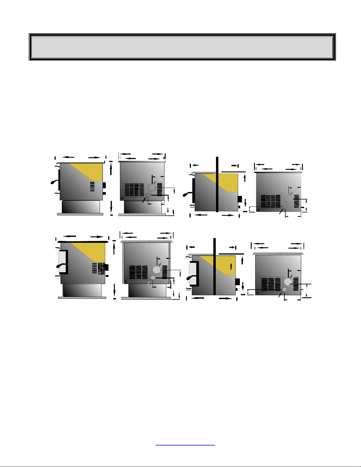
DIMENSIONS
24 3/4
24”
28 3/4”
24 3/4
24”
24”
Air I nlet
Air I nlet
+
+
Traditional Freestanding
+
+
6 1/2”
6 1/2”
8 1/4”
8 1/4”
Exhaust
Exhaust
12 3/4”
12 3/4”
17 1/4”
17 1/4”
Shroud 1
12 1/4” 10 3/4”
18 3/4”
3 ½”
24”
24 3/4”
Air I nlet
Traditional Insert / Built-In
24”
6 1/2”
Exhaust
+
+
8 1/4”
7 3/4”
24”
30”
26”
25”
+
+
+
Air In let
Air In let
8 1/4”
Bay View Freestanding
7”
Exhaust
Exhaust
12 3/4”
17”
Shroud 1”
12 1/4” 10 3/4”
Adjustable
Hopp er
24”
19”
23”
3 ½”
Bay View Insert / Built-In
26”
24”
Air Inl et
6 ½”
Ex haust
Ex haust
+
+
+
7 3/4”
8 1/4”
ELECTRICAL SPECIFICATIONS
Electrical Rating = 110-120 Volts 60 HZ 2.0 Amps
Watts (operational) = 175 (approximately)
Watts (optional igniter) = 475 (approximately)
A voltage surge protector or ground fault outlet is required for this unit.
EPA COMPLIANCE
This heater is exempt from EPA Phase II requirements, but has been tested for emissions using EPA test methods
by Warnock Hersey , US.
FUEL CONSIDERATIONS
Your Pelpro pellet appliance, is designed to burn pellets that comply with Association of Pellet Fuel Industries
standards. (Minimum of 40lbs density per cubic ft, ¼ to 5/16’ diameter length no greater than 1.5”, not less than
8,200 BTU’s/lb, moisture under 8% by weight, ash under 1% by weight, and salt under 300 parts per million)
Pellets that are soft, contain excessive amounts of loose sawdust, have been or are wet, produce clinkers and/or
heavy ash will result in reduced performance and may actually cause the fire to go out.
adian Comfort Industries V04 6 PELPRO OWNERS MANUAL
Can
Copyright 2004
www.pelprostoves.com Dansons Group Inc.
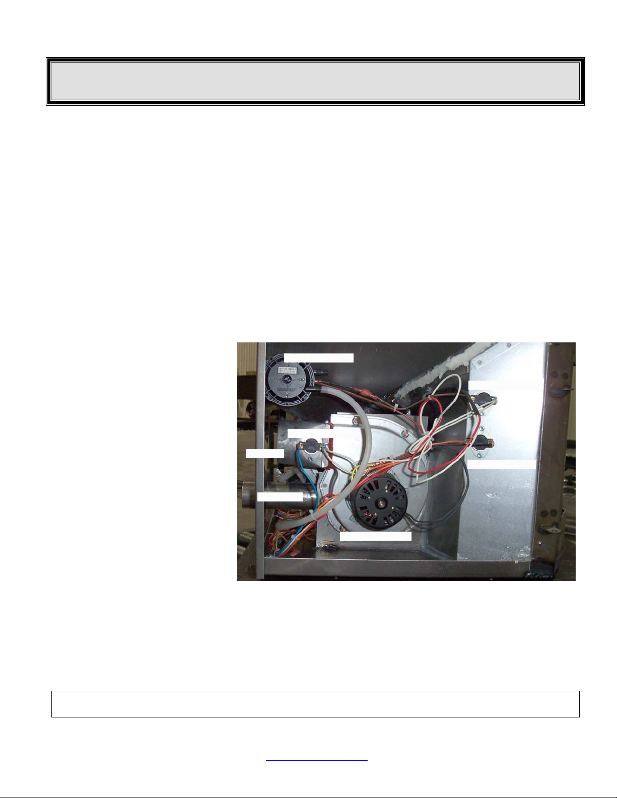
AUTOMATIC SAFETY FEATURES
L250 HIGH LIMIT SWITCH
Your pellet appliance has a high temperature limit switch installed. If the temperature at the back of the firebox
reaches approximately 250deg F., the switch will shut off the electricity going to the Vacuum Switch and to the
Auger Motor. The auger will automatically stop, and the appliance will shut down when the exhaust temperature
cools (120deg F). If this happens call your dealer or Dansons Customer Service (1-866-456-9269).
IT IS IMPORTANT TO FIND THE REASON WHY THE UNIT OVERHEATED.
L120 LOW LIMIT SWITCH
This limit switch is mounted on the exhaust blower housing and has 2 main functions.
1. Should the fire happen to go out, for any reason, this limit switch will shut the stove off when the exhaust
temperature drops below 120deg F.
2. Upon starting the appliance, the AcuTron control board has a 15 minute “Lighting Mode”, if the stove
exhaust does not reach 120deg F in that 15 minutes the stove will shut off. As soon as the stove exhaust
F140 FAN LIMIT SWITCH
Your pellet appliance has a convection fan control limit switch. The room air fan's (F140) temperature limit snap
switch automatically sets the fan on high when your stove is producing heat faster than the fan is carrying it into the
room. This may occur when the heat control lever is set at [3 or 4] and the FAN SPEED is set to a very low or off
setting. After the fan runs at this
automatic high setting a few minutes,
it may cycle back to its lower setting
and may continue to cycle between
[HIGH] and your selected setting.
The circulation (room air) fan cycling
from high to low is a normal condition
as well as a safety feature of your
appliance. To compensate for the fan
cycling, adjust the FAN SPEED to a
higher setting.
VACUUM SWITCH
This safety device (mounted on the
back panel pillar) detects vacuum in
the exhaust system, firebox, and air
intake. If the exhaust blower fails, the
vent pipe becomes plugged, the
viewing door is open, or if you are out
of pellets, this switch will sense that
there is no airflow and will stop the
auger from continuing to feed pellets.
If the power does go out, the pellet appliance will stop running. When the power comes back on,
the stove will not restart if the switch is in the manual mode. If the exhaust temperature is above
120deg F or the switch is in the manual position, the stove will start to feed pellets again and may
re-light itself.
NOTE: If power outages are a concern you may wish to purchase a battery back-up system. It must state “For
Igniter Equipped Appliance” and be a minimum of 750 watts.
For further information contact your local Specialty Retailer, Certified HVAC Service Depot, or Dansons
Group Inc. Customer Service Department at 1-866-456-9269.
does reach 120deg F, the limit switch opens and the AcuTron enters a 5 minute “Safety Delay” mode.
Vacuum Switch
High Lim it L 250
Low Lim it L120
Exhaust
Fan Limit F140
Air Intake
Combustion Fan
AcuTron Wiring Harness
adian Comfort Industries V04 7 PELPRO OWNERS MANUAL
Can
Copyright 2004
www.pelprostoves.com Dansons Group Inc.
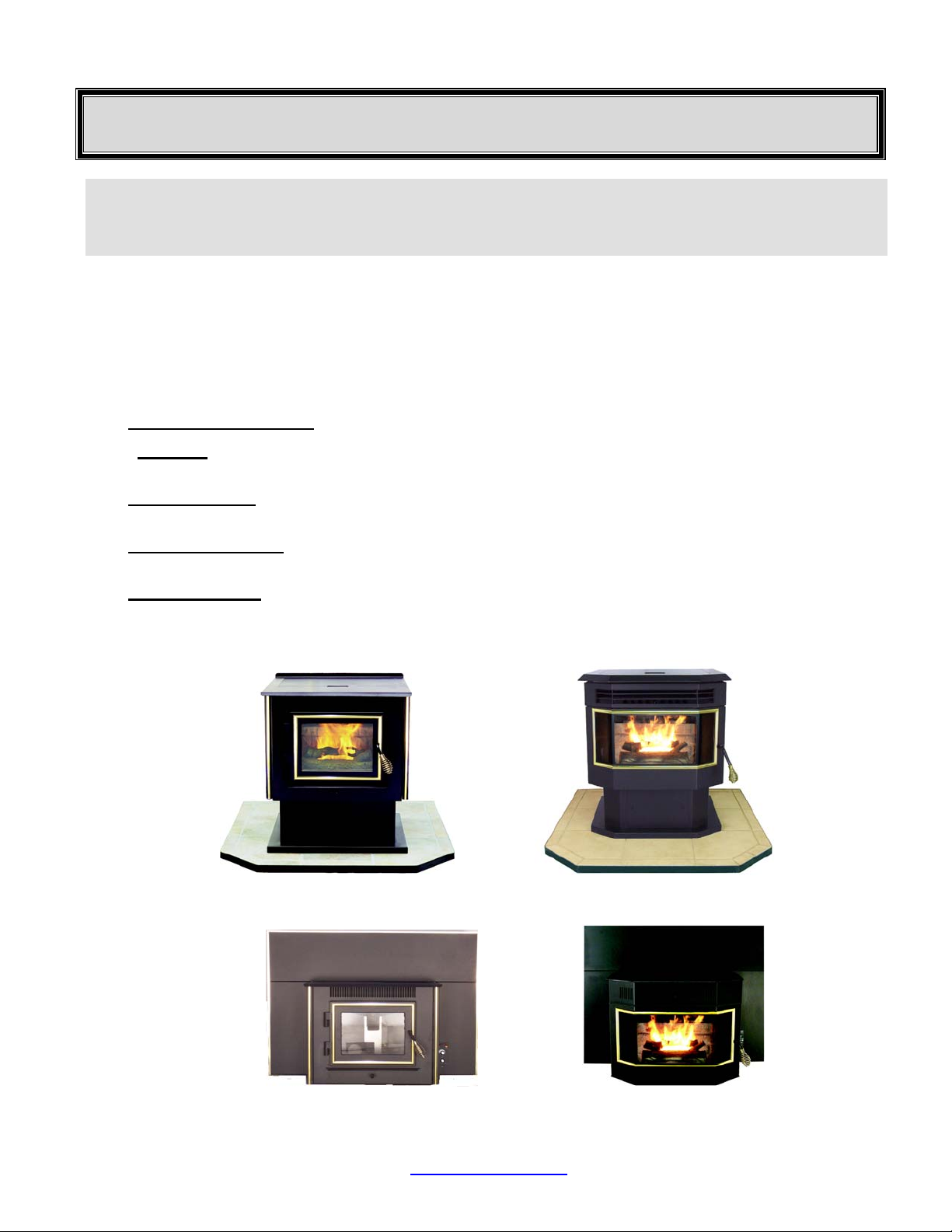
INSTALLATION OPTIONS
READ THIS ENTIRE MANUAL BEFORE YOU INSTALL AND USE YOUR
PELPRO HEATER. FAILURE TO FOLLOW INSTRUCTIONS MAY RESULT IN
PROPERTY DAMAGE, BODILY INJURY OR EVEN DEATH!
(See specific Installation details for clearances and other installation requirements)
The two PELPRO models are the: “FPP” Freestanding: a Traditional styled stove (figure 1), and a Bay View
style(figure 2); and the “IPP” Fireplace Insert / Built-In: a Traditional style (figure 3), and a Bay View style (figure
4). Both models come with either black painted or brass trimmed doors.
All models may be installed to code in both conventional and mobile homes.
INSTALLATION OPTIONS INCLUDE:
1. A FREESTANDING STOVE: Set on a pedestal and placed on a non-combustible floor pad. (figure 1 &2)
2. An ALCOVE: Set on a pedestal and placed on a non-combustible floor pad in compliance with clearance
requirements for an installation in an alcove. (figure 1 & 2)
3. A HEARTH STOVE: When installed with or without a pedestal on a non-combustible hearth of a masonry or
factory built wood or coal burning fireplace. (figure 1 & 2)
4. A FIREPLACE INSERT: When installed, with a shroud, in a masonry or a factory built, wood or coal burning
fireplace. (figure 3 & 4)
5. A BUILT-IN INSERT: When installed on a non-combustible pad, in a wall or custom built mantel and where
adequate airflow around the stove is provided. (figure 3 & 4)
FPP
Freestanding
Bay View Freestanding
FPP
Figure 1
IPP
Insert / Built-In
Figure 2
IPP
Bay View Insert / Built-In
Figure 4
Figure 3
adian Comfort Industries V04 8 PELPRO OWNERS MANUAL
Can
Copyright 2004
www.pelprostoves.com Dansons Group Inc.
A
INSTALLATION CHECK LIST
Unless you are knowledgeable and experienced in stove installation, we recommend your PELPRO stove
receive a Pre-delivery Check and be installed by your local Specialty Retailer or Certified HVAC Service
Depot.
COMPLETE THIS CHECK LIST PRIOR TO LIGHTING YOUR FIRST FIRE:
_____ Carefully read this "Owner's Manual”. SAVE THIS MANUAL.
_____ Obtain final inspection and approval by local building officials.
_____ Carefully clean all marks off the brass parts before the first fire is lit. Use a soft cloth and a gentle type
_____ Polish the hopper to remove the oil type coating used in manufacturing.
_____ Have your local Dealer demonstrate all the operational, cleaning and maintenance steps necessary
_____ Sign and keep a copy of the Pre-delivery Check List supplied by your Authorized Pelpro Dealer,
______ Register your purchase online at www.dansons.com/support.
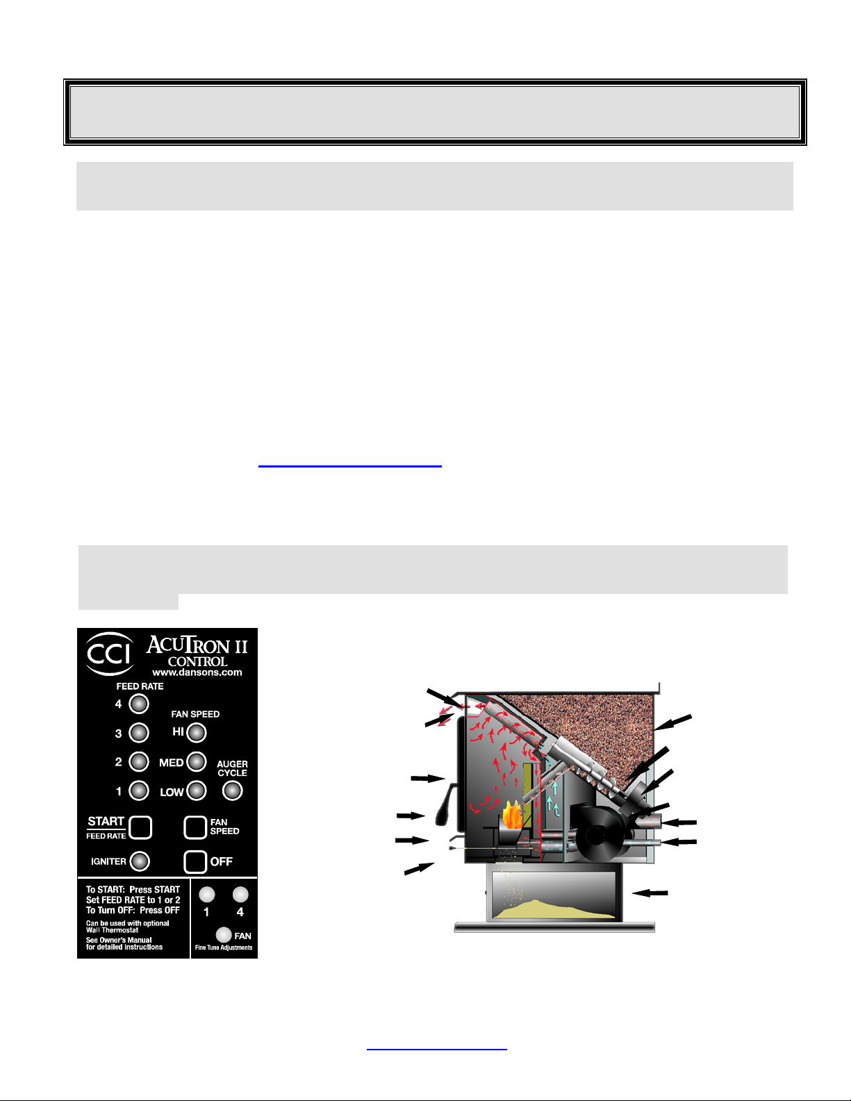
_____ Fill the hopper with quality pellets to prime the unit; Using the CCI “AcuTron”, (figure 5), PUSH the
NOTE: Do not attempt to light a fire at this time. Leave the START / FEED RATE [ON] for 2 to 5 minutes until
pellets start dropping into the burn grate. Then touch the OFF pad to turn off system . The auger is now primed to
deliver fuel to the burn grate (figure 6). Then light the stove according to the directions outlined in "LIGHTING
YOUR STOVE",
CCI –“AcuTron Board” Cutaway View
Figure 3 Figure 4
cleaner. Caution: Never use an abrasive cleaner on any part of your stove.
for your stove.
“Dansons Certified Installer”, found inside our appliance or available online.
Register online at www.dansons.com/support
FEED RATE Touch Pad and this will start the auger and the combustion fan.
Heat Tubes
Tube Scraper
Window
Burn Grate
Burn Pot
E Z Clean
Grate
for Extended Warranty.
Hopper
Auger
Auger Motor
Fan Motors
Exhaust
ir Intake
Ash Pan
adian Comfort Industries V04 9 PELPRO OWNERS MANUAL
Can
Copyright 2004
www.pelprostoves.com Dansons Group Inc.
EXHAUST SYSTEMS (GENERAL)
PELLET VENT MUST MAINTAIN A MINIMUM 3” CLEARANCE TO ANY COMBUSTIBLE
(INSTALL VENT AT CLEARANCES SPECIFIED BY THE VENT MANUFACTURER).
DO NOT CONNECT THE PELLET VENT TO A VENT SERVING ANY OTHER APPLIANCE
OR STOVE.
DO NOT INSTALL A FLUE DAMPER IN THE EXHAUST VENTING SYSTEM OF THIS UNIT.
PELLET VENT TYPE:
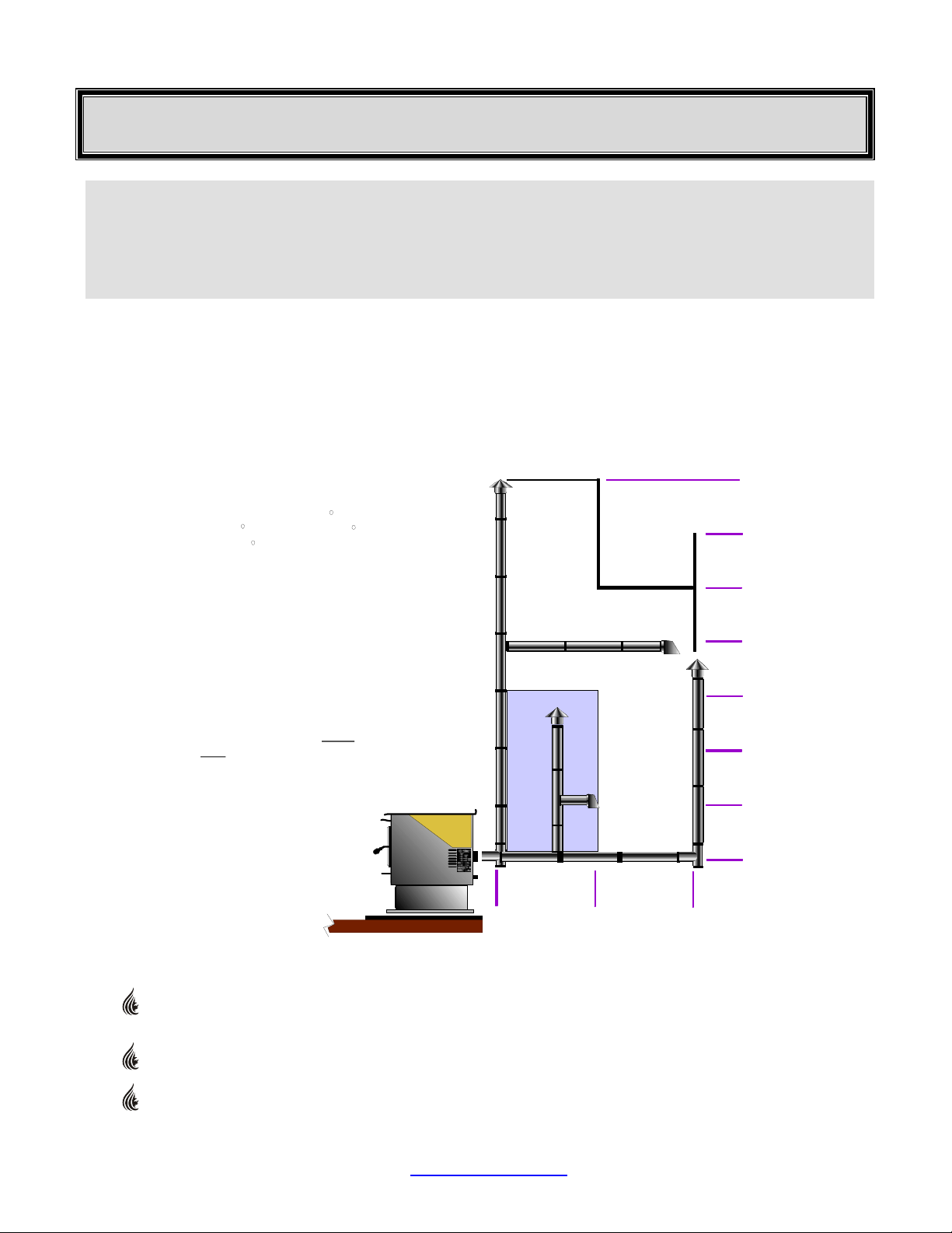
Must be an approved 3” or 4” Diameter Type ”PL” vent, vented to the outside (fig. 7) or connect the vent to a
factory built type “A” chimney using an adaptor; and/or “All Fuel” Stainless Steel chimney liner for masonry
fireplace installations (fig. 8) . Use 4” dia. vent if vent or liner height is over 15’ or if installation is over 4,000’
above sea level.
MAXIMUM VENTING SIZE:
Max imum venting height is 33’.
Maximum horizontal offset is 10’.
Use no more than 180 of elbows
(two 90 elbows, or two 45 elbows
& one 90 elbow, etc) , plus
termination.
Vent must have a support
bracket every 5’ when on
the exterior wall.
If appliance is installed
above 4,000’ elevation,
always use 4” diameter
venting.
Use Diameter “PL” Vent
4”
If venting outside of
shaded area.
Use or Diameter
3” 4”
“PL” Vent, if venting in
shaded area.
33’
30’
25’
20’
15’
Vent height and run
exceed the distance
not
shown in the un-shaded
region of chart.
To achieve optimum
performance, keep vent runs
as short as possible.
Esp ecia lly on hori zont al
installations.
must
10’
5’
0’
0’
5’
10’
VENT INSTALLATION:
Termination must exhaust above the air inlet elevation, and parallel or above the exhaust output of the
pellet appliance. It is recommended that at least 3’ of vertical pipe be installed to create some natural
Can
Copyright 2004
draft. This is to help prevent the possibility of smoke or odor during the appliance shut down.
Horizontal sections must have a ¼” rise every 12” of travel after 3’ long.
Pellet Vent connections must be sealed with HI-Temp RTV Silicone and screwed together with at
least 3 x 3/8” long stainless steel screws. Seal each vent section by injecting a liberal amount of HITEMP RTV silicone sealant into the gap.
adian Comfort Industries V04 10 PELPRO OWNERS MANUAL
www.pelprostoves.com Dansons Group Inc.
EXHAUST SYSTEMS . . . Continued
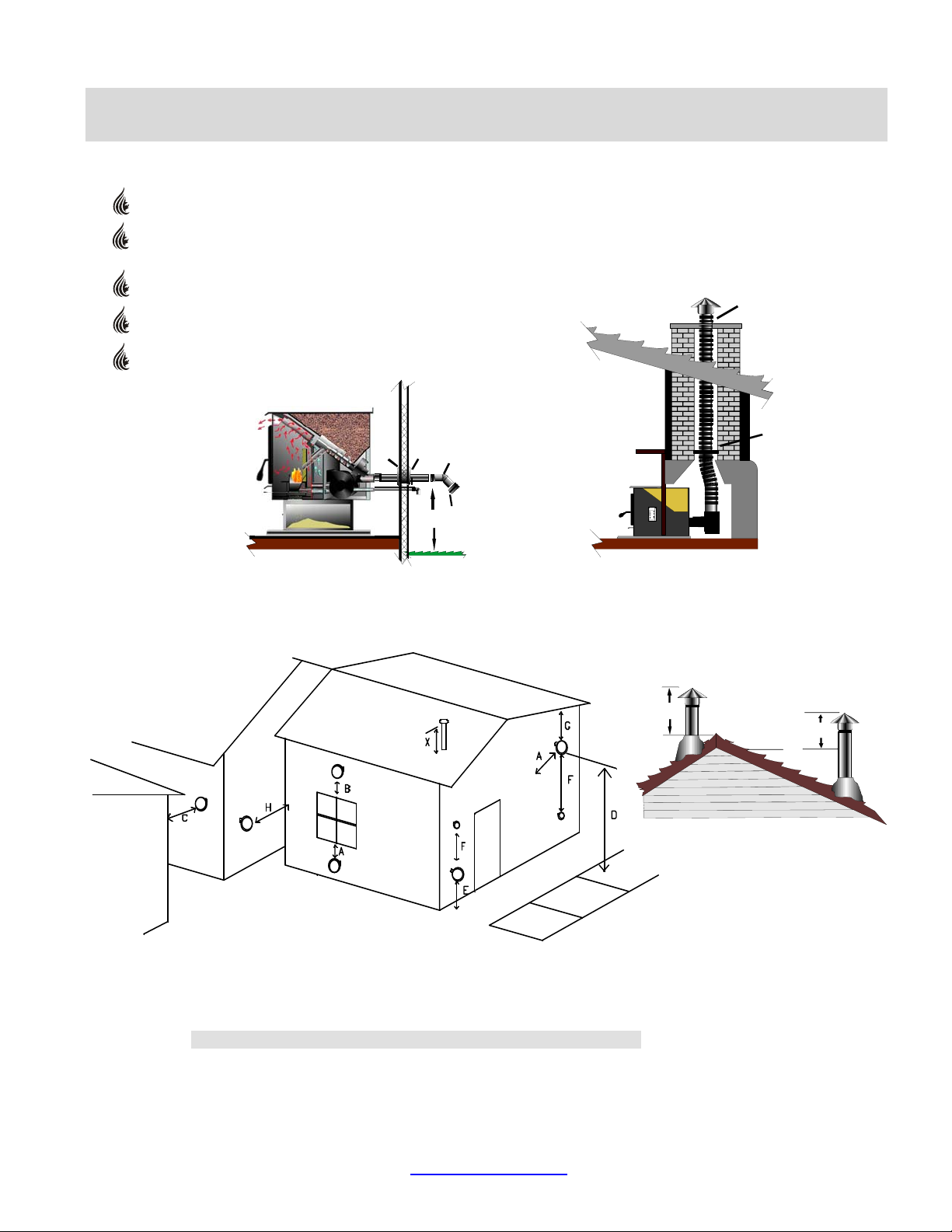
PELLET VENT TERMINATION: (Figures 7 & 8)
Termination must be a minimum of 6” above the chimney (B) (note: the chimney must meet local
codes for height above the roof or other obstructions)
Must have an approved cap (to prevent water from entering) or a 45* elbow downturn
If the termination is located on a windy side of house, an approved house shield is recommended to
prevent soot from accumulating on the side of the house.
Must not be located where snow or other materials will plug it.
Must have a “Metal Seal Plate” or “Wall Thimble” at point (A)
A
A
F
B
A
4
Figure 7 Figure 8
12”
G
VENT TERMINATION CLEARANCES:
• Horizontal terminations must protrude 12” from the wall, vertical terminations 24”
Figure 9
A Minimum 4’ clearance below or beside any door or window which opens.
B Minimum 1’ clearance above any door or window that opens.
C Minimum 3’ clearance from any adjacent building.
D Minimum 7’ clearance above any grade when adjacent to public walkways.
NOTE: Vent may not terminate in covered walkway or breezeway.
E Minimum 2’ clearance above any grass, plants, or other combustible material.
F Minimum 3’ clearance from any forced air intake of any other appliance.
G Minimum 2’ clearance below eves or overhang.
H Minimum 1’ clearance horizontally from combustible wall
X Must be a minimum of 36” above the roof and 24” above the highest point of the roof within 10’.
adian Comfort Industries V04 11 PELPRO OWNERS MANUAL
Can
Copyright 2004
www.pelprostoves.com Dansons Group Inc.
.
3’
x
10’
2’
OUTSIDE AIR
Outside air is REQUIRED ON ALL MOBILE HOME INSTALLATIONS.
Outside air is strongly recommended for all other installations. Failure to install intake air may result
in improper combustion as well as the unit smoking during power failures.
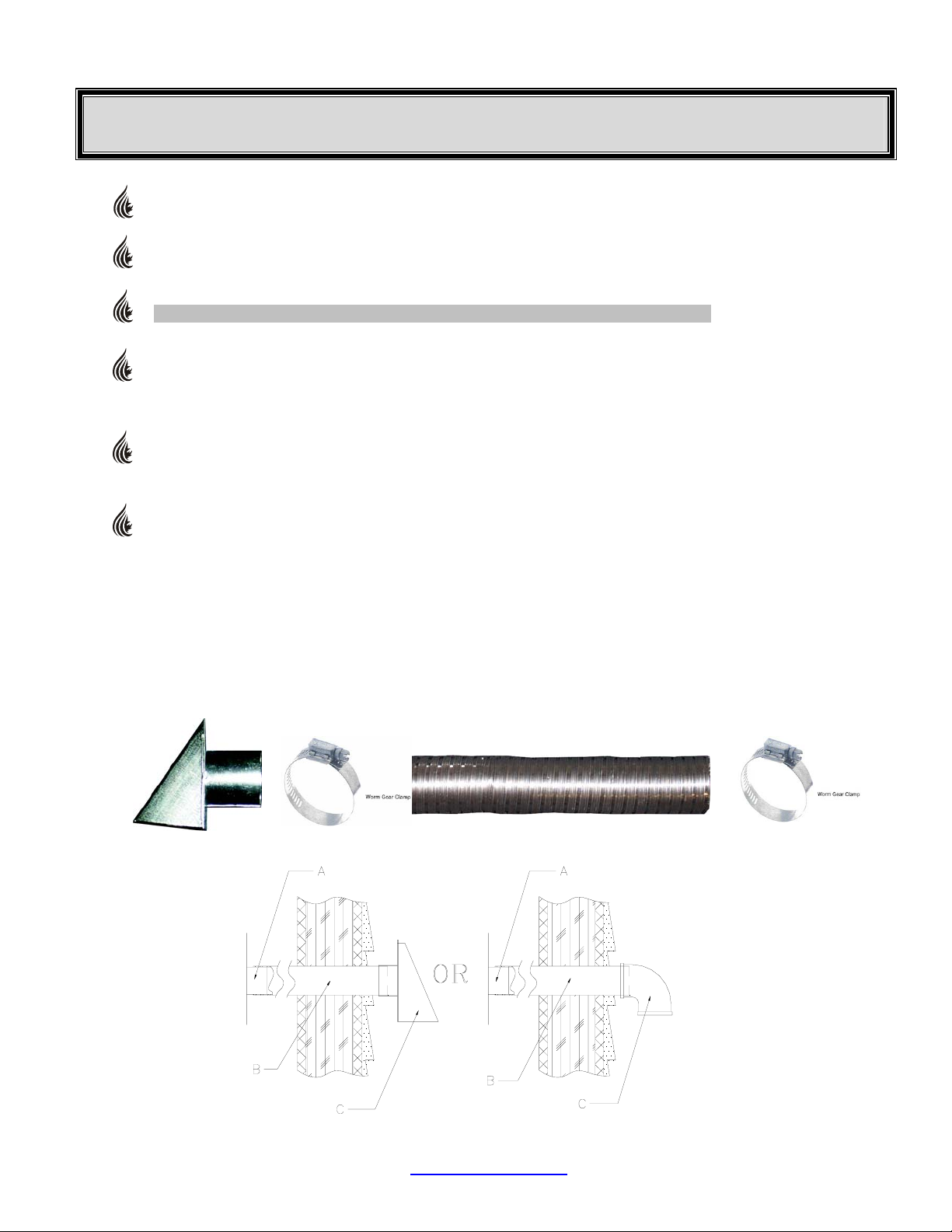
Metal pipe, ONLY, either solid or flexible, must be used in all outside air installations.(B)
NOTE: Non-metallic material MUST NOT BE USED for outside air installations.
A wind shield, (C), over the termination of the outside air pipe or a 90 degree elbow or bend directed
away from the prevailing winds MUST be used when an outside air pipe is installed through the side
of a building. Keep the outside air pipe termination at least 1 foot away from the exhaust system
termination.
When outside air is taken from an existing chimney the exhaust system must not terminate in the
same chimney.
The outside air pipe on your stove is 2" OD. The outside air connecting pipe must be at least 2" ID
The outside air connecting pipe must be as short and free of elbows as possible, and must fit over,
(A), not inside, the outside air pipe on your stove.
Through The Wall Kits Include:
3 FOOT PACKAGE – PART# ACFAKT3 10 FOOT PACKAGE – PART# ACFAKT10
1 – 2” Galvanized Hood c/w screen 1 – 2” Galvanized Hood c/w screen
1 – 2” Aluminum Flex Duct – 1 – 2” Aluminum Flex Duct –
compressed 15” length, extends to 30” – 36” compressed 4’ length, extends to 120”
2 – 2” Worm Gear Clamps 2 – 2” Worm Gear Clamps
NOTE: Available from your local Authorized Dealer or Dansons Group Inc. 1-877-303-3134
Figure 9
adian Comfort Industries V04 12 PELPRO OWNERS MANUAL
Can
Copyright 2004
www.pelprostoves.com Dansons Group Inc.

W
FREESTANDING STOVE INSTALLATION
STOVE PLACEMENT:
FLOOR PROTECTION REQUIREMENTS:
MINIMUM CLEARANCES TO COMBUSTIBLES (FIGURES 10 – 15)
1” From Back Of Heater To Combustibles 3” From PL Vent to Combustibles
2” From Side of Heater to Combustibles
1” From Back Corner of Heater to Combustibles 6” Non Combustible Surface In Front Of Heater
16” From Top Of Heater to Combustibles 36” to drapes, doors, anything that can swing
CLEARANCES – “STRAIGHT INSTALLATION”:
Stove must be placed so that no combustibles are within, or can swing within (i.e. drapes doors),
36” of the heater.
If the stove is placed in a location where the ceiling height is less than 7’, it must follow the
requirements in the section “Alcove Installation”.
Stove and floor protection must be installed on a level secure floor
The stove must be installed on a non-combustible floor protector (i.e. sheet steel with cement, tile or
slate) extending the full width and depth of the stove and extending 6” in front of the stove. Floor
protector needs to be a minimum of 24.5” deep X 30.5” wide and must be a minimum of .018” thick
(26 gauge).
Must extend under and 2” to each side of chimney tee (if used).
HROUGH HE ALL
T T
12”
NTERIOR ERTICAL
I V
3”
1”
1”
10”
2”
6”
6”
Figure 10 Figure 11
6”
2”
adian Comfort Industries V04 13 PELPRO OWNERS MANUAL
Can
Copyright 2004
www.pelprostoves.com Dansons Group Inc.

FREESTANDING INSTALLATION . . . continued
CLEARANCES – “CORNER INSTALLATION”:
45 C
HROUGH HE ALL
T T W
ORNER
12”
45 C
ORNER
NTERIO R
I
V
ERTICAL
1”
3
”
1”
2”
6
”
2
”
6”
Figure 12 Figure 13
Note: If interior vertical vent is used, the clearance to the back wall is determined by the upward-turned
elbow or “Tee”. It will vary in depth depending on the brand of PL vent used.
Before placing the stove, connect the elbow or “Tee” and measure off the 3” clearance.
ALCOVE INSTALLATION:
Minimum clearances to combustibles for a stove. (Figures 14 and 15)
1 inch from the back
16 inches from the top
6 inches from the sides
30 inches deep
LCOVE HROUGH HE ALL
A - T T W
12”
1”
1”
6”
6”
6”
Figure 14 Figure 15
10”
6”
16”
adian Comfort Industries V04 14 PELPRO OWNERS MANUAL
Can
Copyright 2004
www.pelprostoves.com Dansons Group Inc.

A
A
J
FREESTANDING INSTALLATION . . . continued
THROUGH THE WALL, DIRECT INSTALLATION. (Figure 16)
1. Select the location for your stove, design the exhaust system and determine the brand and size of "PL" vent to
be used.
2. Position the floor pad, (C).
3. Following the "PL" vent manufacturer's specifications, mark and cut a hole through the wall to accommodate the
wall thimble, (A), and the outside air pipe, (B), if outside air is to be used. Install the wall thimble, (A). Be sure to
run a bead of silicone around the outside edges of the wall thimble to reduce drafts. Insert the proper size of
"PL" vent, (D), through the wall thimble, (A). Place your stove on the floor pad, (C), close to its final position.
Leave room to connect the "PL" vent to your stove. Place a bead of RTV silicone around the end of your stove's
exhaust pipe, (E). Connect the “PL” vent pipe adaptor (J) onto the stoves exhaust pipe. Connect the length of
"PL" vent, (D), that is in the thimble, (A), onto the pipe adaptor (E). Fasten together with at least three sheet
metal screws (approx. ½” in length). Place a bead of RTV silicone around the connection. Place your stove in its
final position on the pad. Place another bead of RTV silicone around the “PL” vent and the inside of the wall
thimble, to stop cold air drafts.
4. Note: If 4" PL vent is required, use an increaser, (J), on the stove exhaust pipe.
5. On the outside of the building, place a 45 degree "PL" type elbow, (F), onto the end of the horizontal "PL" vent,
(D). Optionally, place a rodent screen cap, (G), (may be required in some locals), on the end of the elbow, (F).
Secure all connections using 3 sheet metal screws and run a bead of RTV silicone around all connections. Also
run a bead of RTV silicone around the “PL” vent pipe and the outside of the wall thimble.
6. If outside air is used, install the outside air pipe, (B). Seal the outside air pipe, (B), to your stove's outside air
pipe, (I), with RTV silicone. Make sure the outside air pipe fits over, (
Install a wind shield (H). Run a bead of silicone around the inside and outside walls, again to reduce cold drafts.
not inside), your stove's outside air pipe.
NOTE: Some horizontal, through the wall installations may require a Clean-Out Tee and a minimum 3’ vertical rise
of pipe outside the building to help draft the stove. This is required if a proper burn cannot be maintained, after the
stove has been tested and the airflow set. This is due to backpressure in the exhaust, caused by the airflow around
the house.
adian Comfort Industries V04 15 PELPRO OWNERS MANUAL
Can
Copyright 2004
12”
6”
6”
A PL Wall Thimble
1”
1”
10”
2”
B Outside Air Intake
C Hearth Pad
D PL Vent Length
E Stove Exhaust
F PL 45 deg elbow
G PL Screened End Cap
H Fresh Air Hood
I Combustion Air Intake
J PL Pipe Adaptor
E
4
Figure 16
www.pelprostoves.com Dansons Group Inc.
C
D
B
H
F
G

A
FREESTANDING INSTALLATION . . . continued
VERTICAL INSTALLATIONS: (Figures 17 - 22)
Your stove may be installed using many different vertical designs. Follow the same basic steps in locating
your stove, attaching the exhaust system and outside air intake to your stove as described in
"FREESTANDING INSTALLATION" and the "PL" vent manufacturer's procedures for installing through a
wall, ceiling, eve and roof.
COMMON, (but not inclusive), VERTICAL INSTALLATION DESIGNS ARE:
VERTICAL, THROUGH THE CEILING, through another room, space or attic, then through the roof,
terminating with a rain cap. Figure 17.
VERTICAL, UP TO AN EXISTING CLASS A CHIMNEY OR MASONRY CHIMNEY. An appropriately
sized adapter will be needed when connecting onto either a Class A chimney or into a masonry chimney.
NOTE: The connection into a masonry chimney must be airtight. Figures 18,19 and 21.
HORIZONTAL, OUT THE WALL, THEN VERTICAL to a minimum of 5 feet, into a 90-degree elbow and
terminating with a 45-degree elbow pointed downward. Figure 20.
HORIZONTAL, OUT THE WALL, THEN VERTICAL THROUGH THE EVES AND ROOF
with a rain cap. Figure 22.
Figure 17 Figure 18 Figure 19
B
, terminating
16”
Figure 20 Figure 21 Figure 22
adian Comfort Industries V04 16 PELPRO OWNERS MANUAL
Can
Copyright 2004
www.pelprostoves.com Dansons Group Inc.

A
MOBILE HOME INSTALLATION
CAUTION: DO NOT INSTALL STOVE IN SLEEPING ROOM
THE STRUCTURAL INTEGRITY OF THE MANUFACTURED HOME FLOOR,
CEILING/ROOF MUST BE MAINTAINED!
Your PELPRO stove has been tested and listed for mobile home installation. It may be installed in a mobile
home as a "Free Standing Stove", a "Hearth Stove", or as an "In Insert" installed in an existing wood or coalburning fireplace or as an "Built –In Insert" installed with a mantel.
In addition to all previously detailed installation requirements, mobile home installations
must meet the following requirements:
Permanently bolt your stove to the floor, (A). Figure 23, 24
Electrically ground your stove or the pedestal to the steel frame of the home. Use a number 8 gauge copper
wire, (B) figure 24, or equivalent.
The stove must have a permanent outside air source with a ¼ inch screen over the inlet.
Figure 23, (B,C, D)
For transportation all chimney / vent above the mobile home must be removed.
“PL” Vent must be 3” or 4” PL Vent and must extend a minimum or 36” above the roofline of the
mobile home and must be installed using a UL/ULC listed ceiling fire stop (J), figure 23, and
rain cap (L), figure 23.
INSTALL VENT AT CLEARANCES SPECIFIED BY THE VENT MANUFACTURER.
Floor Pad
A
Combustion Air Intake
L
K
J
I
H
G
B
C
D
Figure 23 Figure 24
Note: When moving your Mobile Home, all exterior venting must be removed while Mobile Home is
being relocated. Upon completion of relocation all venting must be reinstalled and securely fastened.
B
Fresh Air Duct
C
Fresh Air Hood
D
Stove Exhaust
E
Pipe Adapter
F
Clean Out Tee
G
Tee Support Bracket
H
Pipe
I
Firestop Spacer / Ceiling Support
J
Roof Flashing / Storm Collar
K
Rain Cap
L
HEARTH PAD
FLOOR
GROUND
B
WIRE
FRAME
A
BOLT(S)
adian Comfort Industries V04 17 PELPRO OWNERS MANUAL
Can
Copyright 2004
www.pelprostoves.com Dansons Group Inc.

FIREPLACE INSERT INSTALLATION
VENTING INTO AN EXISTING CHIMNEY:
CAUTION:
MAKE SURE THE CHIMNEY AND FIREBOX ARE CLEAN AND FREE OF SOOT AND ASHES BEFORE
INSTALLATION BEGINS. FAILURE TO DO SO MAY RESULT IN THE TRANSFER OF SOOT INTO THE ROOM
BY WAY OF THE CONVECTION FAN.
The PELPRO Insert may be installed in a masonry or factory built fireplace as shown in Figure 25 & 26
INSTALLING SOLID-FUEL INSERTS INTO FACTORY BUILT FIREPLACES:
The insert must be tested and meet the requirements of UL 1482 (U.S.) and or ULC 8628 (Canada) when
tested in a masonry fireplace built per ULC S628.
The factory-built fireplace must be listed per UL 127 or ULC 8610.
Clearances obtained from the masonry fireplace tests are also relevant for installation in factory-built
fireplaces.
Installation must include a full height listed chimney liner meeting type HT requirements (2100 degree F.)
per UL 1777 (U.S.) or ULC 8635 (Canada). The stainless steel liner must be securely attached to the
insert flue collar and the chimney top.
Means must be provided to prevent room air passage to the chimney cavity of the fireplace. This may be
accomplished by sealing the damper area around the chimney liner, or sealing the fireplace front.
The airflow within and around the fireplace shall not be altered by the installation of the insert (i.e. no
louvers or outlet ports are blocked), unless specifically tested as such for each factory-built fireplace
manufacturer and model line. (Note - using a louvered faceplate (surround) complies with this
requirement).
Alteration of the fireplace in any manner is not permitted with the following exceptions;
1. External trim pieces which do not affect the operation of the fireplace may be removed providing
they can be stored on or within the fireplace for re-assembly if the insert is removed.
2. The chimney damper may be removed to install the chimney liner.
Circulating air chambers (i.e. in a steel fireplace liner or metal heat circulator) shall not be blocked.
Means must be provided for removal of the insert to clean the chimney flue.
Inserts that project in front of the fireplace must be supplied with appropriate supporting means.
A permanent metal warning label must be attached to the back of the fireplace stating
that the fireplace must be restored to its original condition for safe use with out the insert. This sticker is
supplied in the packaging for the insert shroud.
(See Following statement)
THIS FIREPLACE HAS BEEN ALTERED TO ACCOMMODATE
A FIREPLACE INSERT AND SHOULD BE INSPECTED BY A
QUALIFIED PERSON PRIOR TO RE-USE AS A CONVENTIONAL FIREPLACE!
adian Comfort Industries V04 18 PELPRO OWNERS MANUAL
Can
Copyright 2004
www.pelprostoves.com Dansons Group Inc.

N
FIREPLACE INSERT INSTALLATION … CONTINUED
When installing into a masonry chimney, it is recommended that the exhaust vent be extended to the top of
the chimney as shown to the lower right. However, if the vent pipe does not extend to the top of the
Figure 25 Figure 26
chimney, the pipe must extend a minimum of 18” above the damper.
You must seal the damper area with a steel plate when using the direct connection method.
The Vent Pipe Must Extend Above The Damper into the first tile of the flue liner (Figure 25) in the USA and
to the top of the chimney CANADA (Figure 26). The chimney must not be corroded or damaged in any way
for this type of installation to be permitted. A direct vent may be made through the chimney structure if local
codes permit.
FULL CHIMNEY RELINE
DIRECT CONNECTIO
Note: This installation allowed in Canadanot
8”
18”18”18”
6”
18” min.
leng th
Metal
Sealing Plate
Note: This installation recommended
for all chimney installations!
Liner Support
8”
18”
6”
is
Deluxe Cap
Optional
Metal Pl ate
adian Comfort Industries V04 19 PELPRO OWNERS MANUAL
Can
Copyright 2004
www.pelprostoves.com Dansons Group Inc.

BUILT-IN INSERT INSTALLATION
CAUTION: DO NOT BLOCK VENT OPENING
The PELPRO Insert may be framed directly into a wall as either a horizontal or vertical vent installation see (figure
27, 28). The exhaust installation requirements are the same as for a freestanding stove. Refer to “Installing your
Freestanding Stove” for information concerning installation and proper hook-up of the exhaust.
NOTE: Built-In Installations require Enclosure Kit #ACI-3HZ Horizontal Vent or #ACI-3VL Vertical Vent.
Dimensions that will be enclosed within the frame work are:
Shroud 1”
12 1/4” 10 3/4”
24 3/4”
24”
18 3/4”
3 ½”
24”
Traditional Insert / Built-In
Air Inlet
6 1/2”
Exhaust
+
+
7 3/4”
8 1/4”
Horizontal Vent Installation
This example shows the
exhaust venting out and
up vertically
Requires Spacer Kit
#ACI-3HZ
The framed opening for this
Installation needs to be:
Tradition Bay View
Height 21” 21 - 25”
Width 30” 30”
Depth 17” 17”
If constructing a chase, adequate
Shroud
Insulation, vapor barrier, drywall,
And caulking must be used.
6”
4
FIGURE 27
Wood Surround
adian Comfort Industries V04 20 PELPRO OWNERS MANUAL
Can
Copyright 2004
www.pelprostoves.com Dansons Group Inc.
Shroud 1”
12 1/4” 10 3/4”
Adjustable
Hopper
24”
19”
23”
Bay View Insert / Built-In
Exterior Wall
2’
10’
Wood Frame
8”
18”
Construction
2” Min.
Air gap
6”
Stand Offs
Part ACI-3HZ
3 ½”
26”
24”
6 ½”
Ex haust
Ex haust
+
+
+
Ai r Inlet
3” minimum
air gap
Wall Band /
Support Brkt
every 5’
Clean Out Tee
8 1/4”
7 3/4”

V
V
BUILT-IN INSERT INSTALLATION . . . CON’T
PELLET VENT MUST MAINTAIN A MINIMUM 3” CLEARANCE TO ANY COMBUSTIBLE (INSTALL
VENT AT CLEARANCES SPECIFIED BY THE VENT MANUFACTURER).
DO NOT CONNECT THE PELLET VENT TO A VENT SERVING ANY OTHER APPLIANCE OR STOVE.
DO NOT INSTALL A FLUE DAMPER IN THE EXHAUST VENTING SYSTEM OF THIS UNIT.
ertical Vent Installation
Interior
2’
10’
Ceiling Support /
Firestop Spacer
Wood Frame
Constructi on
8”
Wall B and /
18”
Shroud
6”
Support Brkt
every 5’
3” minimum
air gap
ertical Vent Installation
Chase
2’
8”
18”
Shroud
6”
Rain Cap
Storm Collar
Metal
Chase Cap
Ceiling Support /
Firestop Spacer
Wood Frame
Construction
Wall Band /
Support Brkt
every 5’
3” minimum
air gap
Wood Surround
Stand Off
Part ACISOVL
Clean Out Tee
Wood Surround
Stand Off
Part ACISO VL
Clean Out Tee
Figure 28
These examples show two styles of vertical install. These require Spacer Kit # ACI-3VL.
The framed openings for these installations need to be:
Tradition Bay View
Height 21” 21 - 25”
Width 30” 30”
Depth 17” 17”
If constructing a chase, adequate, insulation, vapor barrier, drywall, and caulking must be used.
adian Comfort Industries V04 21 PELPRO OWNERS MANUAL
Can
Copyright 2004
www.pelprostoves.com Dansons Group Inc.

OPERATING YOUR STOVE
The operations and maintenance of your PELPRO stove are unique and should not be considered to be like a
wood, coal stove, gas, electric, propane or oil heater.
Cautions:
Do not try to operate your stove with viewing or ash pan doors open. Pellets will not feed under these
circumstances and a safety concern may arise from sparks or fumes entering room.
Burn only pellet fuel that complies with PFI standards. Burning other types of fuels may result in the
formation and leakage of Carbon Monoxide which if undetected can be deadly.
If you are not drawing combustion air from outside, care must be taken to allow for adequate air
make up, to avoid possible room air starvation when stove or other exhaust fans are in operation.
It is recommended that you install a high quality smoke detector in the room where stove is installed.
HOW YOUR PELPRO STOVE WORKS
Fuel in the form of wood pellets is stored in the hopper. An auger delivers the pellets to the burn grate. The fuel
rate, or heat output, is set by adjusting the feed rate touch pad, (settings 1 to 4). A fan provides combustion air to
the burn grate. The amount of combustion air in the burn grate is adjustable and automatically changes as the fuel
rate changes. The higher the fuel rate, the larger the amount of combustion air and visa versa. The fuel burns in
the burn grate, producing heat. Some heat radiates out the front of your stove. The majority of the heat passes
around the heat exchange tubes and air plenum around the firebox and is then moved into the room by the room air
fan. A small amount of heat must pass out of your stove, along with exhaust gases, into the atmosphere.
Your stove's heat output can be adjusted from setting 1-4,
as the fuel supply is uninterrupted and timely cleaning and
maintenance is performed. An example of how improper
cleaning effects operations is; the exhaust pressure switch
will shut the pellet supply off and your stove will shut off if
the exhaust system becomes plugged.
Care should be taken to make sure detector is in working order at all times.
through the FEED RATE touch
pad, to vary your heat output from
Low to High. The room air fan can
be manually adjusted through the
FAN SPEED to run faster or slower
to correspond to the amount of
heat being produced. The room air
fan is also on a limit switch,
controlled to run on high when the
stove reaches higher temperatures
and then resume the speed you
had selected once it cools to a
lower temperature.
Your stove can run efficiently over
extended periods of time and at
different heat output levels as long
Figure 29
adian Comfort Industries V04 22 PELPRO OWNERS MANUAL
Can
Copyright 2004
www.pelprostoves.com Dansons Group Inc.

LIGHTING YOUR STOVE
Before lighting a fire check to ensure the Burn Grate is clean and adjusted and the Ash Tray is not full.
For safety reasons use extra caution when lighting a stove that is HOT!
Lighting stove manually (No Igniter)
In the NON-Thermostat Mode
1. Push firmly on the FEED RATE or START touch pad.
-The
COMBUSTION FAN (exhaust) will start and
operate at full speed for 60 seconds, then adjust
downward to match feed rate #1
-The
CONVECTION FAN (heating) will start and the
LED will go solid on LOW setting
AUGER CYCLE LED will go solid for 3 seconds,
- The
indicating signal being sent to auger motor.
2. Place a small amount of a solid fuel fire starter, such
as those made from sawdust and wax or use wood
shavings, in the bottom of the burn grate.
Add a small handful of pellets to the starter material.
Add a small amount of fire starter over the pellets.
CAUTION: DO NOT USE ANY FLAMMABLE
LIQUIDS SUCH AS GASOLINE, GASOLINE-TYPE
LANTERN FUEL, KEROSENE, CHARCOAL
LIGHTER FLUID, OR SIMILAR LIQUIDS TO START
OR FRESHEN-UP THE FIRE! KEEP ALL SUCH
LIQUIDS WELL AWAY FROM THE HEATER
WHILE IT IS IN USE.
3. Light the fire starter and slowly close the MAIN
DOOR
, leaving it about 1 inch open. When the
pellets are burning, close and latch the main door. If
the fire goes out when the main door is closed, add
more fire starter, re-light the fire and leave the main
door open an inch or so until the pellets start to burn,
then close and latch the main door.
4. Adjust the FUEL RATE and the FAN SPEED to your
desired settings you require upon completion of
startup sequence.
NOTE: If the fire does not start, your stove will continue to feed pellets and the fans will run for approximately 15
minutes. The stove will then automatically shut off. If this happens, some unburned pellets will build up in the burn
grate. To restart the fire, clean the excess pellets out of the burn grate and follow the above "Lighting a Fire".
NOTE: Some odors may be given off a new stove during the initial few hours of burning while the stove and the
paint are being cured. These odors are not harmful. However, ventilating the room until the odors disappear is
strongly recommended.
CAUTION: Never use liquid or volatile fire starters to start a fire in your stove! Do not install or operate your
stove in any room where any liquid or volatile fuels or any other highly combustible items are in the air or stored in
the room. These could cause a safety hazard.
Lighting stove with Auto-Ignitor
In the NON-Thermostat Mode
1. Push firmly on the FEED RATE or START
touch pad.
COMBUSTION FAN (exhaust) will start
-The
and operate at full speed for 60 seconds, then
adjust downward to match feed rate #1
-The
CONVECTION FAN (heating) will start
and the LED will go solid on LOW setting
AUGER CYCLE LED will go solid for 3
- The
seconds, indicating signal being sent to auger
motor.
IGNITER LED will light up solid and the
-The
300 watt igniter will begin to operate.
2. On a primed AUGER system pellets will begin
to fall into the
SELF IGNITER
pellets in approx. 3 – 5 min.
Note: If stoves fails to light within 15 minutes,
shut off the stove, remove the pellets from the
burn grate and repeat step 2. If stove fails to
ignite a second time, disconnect and contact
your dealer
3. Adjust the
to your desired settings you require upon
completion of startup sequence.
BURN GRATE, and the AUTO
will automatically ignite the
.
FUEL RATE and the FAN SPEED
adian Comfort Industries V04 23 PELPRO OWNERS MANUAL
Can
Copyright 2004
www.pelprostoves.com Dansons Group Inc.

THE CONTROLS
Basic Overview
The AcuTron II or III digital control board was designed to give you flexibility on how
you want to operate your stove. The AcuTron can be operated as a MANUAL
control or by a THERMOSTAT. When operating in the Thermostat option, you can
also choose to run your appliance in the ON/OFF mode or the LOW/HIGH mode.
The START or FEED RATE touch pad allows electricity to flow to your stove's
electrical components for 15 minutes. If after 15 minutes your stove has heated to
normal operating temperatures your stove will continue to run. If the fire does not
light and/or burn properly, the electricity to your stove's components will be shut off
at the end of 15 minutes.
The FAN SPEED controls the speed of the room air fan. This fan blows room air
through the heat exchange tubes and back into the room. When the FEED RATE is
set to a higher position, the FAN SPEED should be set higher and visa versa. To
achieve optimum heat transfer it is recommended to set the FAN SPEED to LOW
when running the FEED RATE at 1 or 2, and Fan on MED on FEED RATE #3 or 4.
When the START / FEED RATE is ON, the AUGER CYCLE LED will turn on when
as desiredas desired
HOW THE BOARD WORKS
INITIAL START OR SET-UP (MANUAL OR NON-THERMOSTAT MODE)
Upon initial start-up the control will feed automatically at the #1 feed rate.
Press the START touch pad.
- Convection (heating) fan will start and the FAN LED will be solid on LOW setting
- The 300 watt Auto-Igniter will begin to glow and the IGNITER LED will be solid
- The AUGER CYCLE LED will go solid for 3 seconds, indicating signal is being sent to the auger motor.
- The Combustion (exhaust) fan will start and operate at full speed for 60 seconds, then adjust downward to match
feed rate #1.
Press FEED RATE touch pad to select desired heat output that you require upon completion of ignition sequence.
NOTE: If you do not press the FEED RATE touch pad, the stove will continue to run at FEED RATE #1 and the LED will continue
to flash at a fast rate.
When the FEED RATE LED is flashing at a FAST rate this indicates that the LOW LIMIT (L120) is closed. This means the unit
has not reached operating temperature.
When the FEED RATE LED is flashing at a SLOW rate this indicates that the LOW LIMIT (L120) is open. This means the control
board has entered a 5 minute “Safety Delay” mode.
After the 5 minute Safety Delay is complete
- IGNITER and INGNITER LED will turn off
- FEED RATE LED will become solid and the appliance will feed fuel at your selected heat output
RE-START (MANUAL OR NON-THERMOSTAT MODE)
The AcuTron II or III board does have limited memory. To restart your appliance push the START touch pad. The appliance will
automatically go through it normal start-up then return to the FEED and FAN setting you used prior to turning off the board and
appliance the last time of use.
the auger is active. When the OFF touch pad is pushed [OFF], the auger motor will
not run, fuel stops feeding and the fire will die.
The FEED RATE works in a synchronized manner setting both the fuel rate and
combustion air at the same time. When fuel is increased by setting the FEED RATE
higher, combustion air is automatically increased and visa versa.
adian Comfort Industries V04 24 PELPRO OWNERS MANUAL
Can
Copyright 2004
www.pelprostoves.com Dansons Group Inc.

A
THE CONTROLS … CONTINUED
TRIM POTS (Fine Tune Adjustments)– Factory Settings
The COMBUSTION FAN (FAN), HI (4) and LO (1) FEED RATE trim pots have been preset at the
factory, but may need to be adjusted onsite after your installation is complete. Due to different
installation setups, length and size of venting, and pellet fuel quality, the preset from the factory will
not always be correct. These settings will accommodate virtually all wood pellet fuels.
FUEL FEED rates at the Lowest (number 1) and highest (number 4) settings can be adjusted by
adjusting the fine tune trim pots located on the control panel. To raise fuel feed turn trim pot
counter clockwise and to lower turn clockwise. To assist in knowing what the change is you
should note the amount of time the light on the AUGER CYCLE LED stays OFF. (Note: The light
stays on when ever the fuel feed motor, AUGER CYCLE, is running). Lengthening the time this
LED stays OFF lowers the fuel feed and shortening the off-time increases the fuel feed
.
COMBUSTION FAN SPEED (FAN)
In a few instances because of prevailing conditions pertinent to your specific installation, or even
different batches of pellet fuel, the COMBUSTION FAN SPEED may be adjusted to raise or lower
the amount of air moving through the grate for the cleanest burn. The FAN speed can be adjusted
by adjusting the FAN trim pot COUNTER CLOCKWISE to INCREASE the speed and CLOCKWISE to DECREASE the speed
of the combustion fan.
Note: If you attempt to adjust the Fuel Feed Trim Pots, use a small precision screwdriver.
The Trim Pots do not make a full rotation.
If using a metal screwdriver, be gentle as the plastic trim pot slot can be damaged or stripped.
FAN SPEED (Convection or heating)
The FAN SPEED controls the speed of the room air fan. This fan blows room air through the heat
exchange tubes and back into the room. When the FEED RATE is set to a higher position, the FAN
SPEED should be set higher and visa versa. When the FEED RATE is set at [3 OR 4] set the FAN
SPEED to [MED]. If you forget, the room air fan's (L140) temperature limit snap switch automatically
sets the fan on high when your stove is producing heat faster than the fan is carrying it into the room.
This may occur when the heat control lever is set at [3 or 4] and the FAN SPEED is set to a very low
or off setting. After the fan runs at this automatic high setting a few minutes, it may cycle back to its
lower setting and may continue to cycle between [HIGH ] and your selected setting. The circulation
(room air) fan cycling
from high to low is a normal condition, as well as a safety feature of
your appliance.
AUGER CYCLE
The AUGER CYCLE LED indicates when a electrical signal is being sent to the auger motor. It is
NOT used to indicate the actual movement of the auger. When the signal is being sent the LED will
be solid for 3 seconds. When the LED is off no signal is being sent
.
Decrease
FINE TUNE ADJUSTMENTS
Increase
14
FAN SPEED
HI
MED
LOW
FAN
SPEED
OFF
FAN
UGER
CYCLE
SHUTTING THE STOVE OFF
Note: DO NOT UNPLUG your stove if there is a fire going or if the stove is still active. This could result in smoke coming back
into the room. Remember the EXHAUST FAN is needed to force the exhaust out of the stove.
On the CCI “AcuTron” Board firmly touch the OFF touch pad. The FUEL RATE LED will turn off. The AUGER CYCLE LED will
turn off. The auger will stop feeding fuel to the fire and the FAN speed LED will flash indicating that the appliance is in the “Shut
Down” mode. The fire will go out and the fans will continue to run until your stove cools down at which time the fans will
automatically shut off and NO LED’s will remain ON.
adian Comfort Industries V04 25 PELPRO OWNERS MANUAL
Can
Copyright 2004
www.pelprostoves.com Dansons Group Inc.

PERFORMANCE ENHANCEMENT TIPS
Quality care and quality pellets will help your stove operate at its peak efficiency. Consider:
fines are noticed in the pellets or in the hopper, you may wish to screen the pellets.
If any
Periodically check the hopper to make sure there are no fines or pellets building up in the corners of the
sloping sides. Clean and polish the hopper as needed.
Be diligent in performing your
IT IS CRITICAL FOR THE CORRECT OPERATION OF YOUR STOVE
THAT THE DAMPER, COMBUSTION FAN SPEED AND HI-LO FUEL
FEED RATES BE SET CORRECTLY!
AIR INLET DAMPER:
The damper is a plate that helps control the amount of airflow supplied for combustion. With the damper pushed all
the way in the airflow is at its minimum. As the damper is pulled out, more air is allowed to flow through the
combustion area.
It will be necessary to monitor the appearance of the flame. Start by running your heater on HIGH (#4) setting for
approximately 10 minutes, then push the damper all the way in and evaluate the appearance of the flame. If your
flame is smoky red / orange with evidence of soot at the top of the flame, you need more combustion air. Continue
to pull out the damper about a 1/8” at a time, opening the damper as needed to obtain a flame that is yellow and a
fire that is brisk enough to carry ash out of the grate, but not so brisk that it carries pellets out as well (known as
“Pop corning”). Normally you should find that the damper will need to be closed two-thirds to three quarters, but will
vary with length of vent run, pellet quality and elevation.
Damper Adjustment Guideline
Lack of Combustion Air:
Symptoms of insufficient combustion
air include
red / orange flame, excessive ash or soot,
excessive buildup on glass, as well as
excessive amounts of ash build up in the
grate.
Contributing factors: High Altitude –
Lack of oxygen, Restrictive Venting, Dirty /
Poor quality fuel or the burn grate may not
be seated properly.
Excessive Combustion Air:
Symptoms of excessive combustion air
include
smoking or smoldering pellets, white to
yellow flame, and the burning pellets will lift
off the grate and fly up into the air (popcorning)
Contributing factors: venting system providing excessive draft.
Refer to the "Trouble Shooting Guide" section of this manual, and if necessary,
Retailer, Certified HVAC Service Depot, or Dansons Group Inc. Customer Service Department at
1-866-456-9269.
: unburned fuel, lazy smoky or
: fuel burns to quickly resulting in
CLEANING and MAINTENANCE requirements.
Stove Back Panel
Air Inlet
Slide Rod
Rubber
GrometT
Right Hand
Side Panel
contact your local Specialty
adian Comfort Industries V04 26 PELPRO OWNERS MANUAL
Can
Copyright 2004
www.pelprostoves.com Dansons Group Inc.

Wall Thermostat (option)
OPERATION
Your pellet appliance is capable of running in an automatic mode with the use of a wall
thermostat. The “AcuTron” gives you a choice, “ON / OFF on Demand” or “LOW /
HIGH”. The ON / OFF mode automatically turns the heater On and will Shut Off on
demand. The LOW / HIGH mode will keep your heater active and cycle between #1
(LOW) setting and your selected (HIGH) setting.
In most circumstances the BEST operation, and recommended, under thermostat
control is the LOW / HIGH cycle.
Upon Start Up, in thermostat mode, the default running mode will be the LOW /
HIGH mode.
When operating in either mode should your unit run out of pellet fuel it will automatically
go through the normal SHUT DOWN cycle. After completing the SHUT DOWN cycle the
appliance will try to restart one time only before shutting off completely, till you refill the
hopper and reactivate the FUEL FEED pad.
as desiredas desired
HIGH / LOW CYCLE Option (Flashing 3 & 4)
Once this mode has been selected, you simply press the START touch pad to activate the stove. You can now select the HIGH
heat output level (2,3 or 4) by pushing the START / FEED RATE touch pad, you can also select the FAN setting you desire.
When you have selected your high level and fan speeds the LED’s will continue to flash. The appliance will automatically start at
the #1 feed rate until the Start-up procedure is complete.
The LOW (number 1) or selected High (2,3 or 4) Feed Rate indicator light will light up depending on if the thermostat is calling for
heat or not. When the desired room temperature is reached the stove will automatically go into the low heat (#1) cycle. When the
temperature in the room drops to the level set at the thermostat, the stove will again cycle to the HIGH (#2,3 or 4) preselected
setting. For optimum heat transfer, the FAN setting should be set at LOW or MEDIUM. The appliance will run the FAN at HIGH
speed when needed, automatically.
ON / OFF Option (Flashing 1 & 2)
To activate the thermostat to the ON / OFF feature, press and HOLD the OFF touch pad. If the FEED numbers 3 & 4 flash
together, you will need to push and hold the OFF touch pad a second time. The numbers 1 & 2 will flash together to indicate that
this is the cycle you are in. You can now select the HIGH heat output level (2,3 or 4) by pushing the START touch pad, you can
also select the FAN setting you desire. The stove will now go through its normal start up cycle. Once completed the appliance is
now in the ON / OFF mode.
The thermostat should be set for the desired room temperature. If the room temperature drops below the level on the thermostat
the stove will automatically begin the start-up cycle, as explained in the manual operation section.
Once the start-up cycle is completed the stove run on the pre-selected “HIGH” (number 2,3 or4) setting, till the temperature is
reached. For optimum heat transfer, the FAN setting should be set at LOW or MEDIUM. The appliance will run the FAN at
HIGH speed when needed, automatically.
When the desired room temperature is reached the stove will automatically go into the shut down cycle. The pellet feed will stop
and the blowers will continue for a controlled time allowing safe shut down of your heater. When the temperature in the room
drops to the level set at the thermostat, the stove will again begin the start-up cycle and resume automatic operation.
The Feed Rate numbers 1 & 2 will flash while the appliance is in the OFF part of this mode to give you a visual
indication that the appliance is still active and in the ON / OFF cycle.
TO CHANGE BETWEEN THE TWO MODES,
Press and hold the OFF touch pad firmly, for 3 to 5 seconds, when the FEED RATE
LED’s #3 and #4 flash together this indicates the thermostat will run in the HIGH / LOW
cycle. When the #1 and #2 LED’s flash together this indicates the ON / OFF cycle has
been chosen.
adian Comfort Industries V04 27 PELPRO OWNERS MANUAL
Can
Copyright 2004
www.pelprostoves.com Dansons Group Inc.

INITIAL APPLIANCE BURN SETUP
IT IS CRITICAL FOR THE CORRECT OPERATION OF YOUR STOVE THAT THE BURN
GRATE, AIR INLET DAMPER, COMBUSTION FAN SPEED, AND
1 & 4 FUEL RATE BE SET CORRECTLY!
A HIGH QUALITY FIRE should burn with a brisk, yellow flame. A flame exhibiting a lazy, orange or sooty
characteristic is a poor quality and inefficient flame. A poor flame produces less heat, increases sooting and may
cause a smoky exhaust. If a poor flame exists for any period of time, clean your stove and exhaust system.
Note: if log option is purchased, do not install until initial setup is complete
FEED RATE
4
3
2
1
START
FEED RATE
START APPLIANCE AS PER LIGHTING INSTRUCTIONS,
let stove run for approx. 10 minutes before turning the stove to the # 4 setting (or High), to
begin to make fine adjustments. AUGER CYCLE indicator should be lit “ON” for 3 seconds
and “OFF” for 3-5 seconds. Adjust the AIR INLET DAMPER. This will have to be set, as the
factory sends all units out with the damper wide open to accommodate a wide range of
installations and elevations.
AIR INLET DAMPER: Slide open or close
damper as needed to obtain a fire that is brisk
enough to carry ash out of the grate, but not so
brisk that it carries pellets out as well (known as
“Pop corning”). Normally you should find that the
damper will need to be closed two-thirds to three
quarters, but will vary with length of vent run, pellet
quality and elevation. The best way to set this is at
the FUEL SETTING #4.
Air Inlet
Slide Rod
Stove Back Panel
Rubber
GrometT
Right Hand
Side Panel
FEED RATE
4
3
2
1
START
FEED RATE
When you are pleased with the burn and how the appliance is operating, you
are now ready to set the board up at LOW setting.
Set FUEL RATE to #1 or LOW setting. Again let this burn for
approx. 10 minutes before making any adjustments. The AUGER
CYCLE indicator should be “OFF” for approx 9 – 14 seconds
between auger turnings (light ON). If “Pop corning” is taking place
at this setting adjust the
COMBUSTION FAN SPEED.
Decrease
FINE TUNE ADJUSTMENTS
Increase
COMBUSTION FAN SPEED (Draft): In a few instances
because of prevailing conditions pertinent to your specific
installation, or even different batches of pellet fuel, the
COMBUSTION FAN SPEED may be adjusted to increase or
decrease the amount of air moving through the grate for the
cleanest burn. Fan speed can be adjusted by adjusting the FAN
trim pod COUNTER CLOCKWISE to INCREASE the speed and
CLOCKWISE to DECREASE the speed of the combustion fan.
14
FAN
FUEL RATE: Fuel rate at the Lowest (number 1) and highest (number 4) settings can be
changed by adjusting the #1 or #4 TRIM PODS located on the control panel. To INCREASE fuel rate turn trimmer
COUNTER CLOCKWISE and to LOWER turn CLOCKWISE. To assist in knowing what changes you made, you
should note the amount of time the light on the AUGER CYCLE stays “OFF”. (Note: The light stays “off” when ever
the fuel feed motor is not running).
shortening the “OFF” time increases the fuel feed
#4 light “OFF” is 3-4 seconds.
Lengthening the time this light stays “OFF” lowers the fuel feed and
. Factory Setting #1 light “OFF” is approx. 9-11 seconds,
adian Comfort Industries V04 28 PELPRO OWNERS MANUAL
Can
Copyright 2004
www.pelprostoves.com Dansons Group Inc.

PELLET FUEL
The performance of your pellet appliance is greatly affected by the type and quality of
wood pellets burned. As the heat output of various quality wood pellets differ, so will
the performance and heat output of your appliance.
PELLET QUALITY
Your PELPRO stove, with its standard “E Z Clean Grate”, is designed to burn APFI/FFI, "Premium" or "Standard"
quality wood pellets. Pellets that are soft, contain excessive amounts of loose sawdust, have been or are wet,
produce clinkers and/or heavy ash will result in reduced performance and may actually cause the fire to go out.
PELLET CONSUMPTION
Fuel consumption will vary somewhat between fuel brands and stoves. The following "ROUGH GUIDE" to pellet
usage's may be useful in assessing your stove's operation, in ordering fuel and in providing information to your
Authorized PELPRO Dealer.
Fuel Rate Setting…
Setting Approx. Burn time on 40lb hopper Amount of pellets burned
1 20 – 30 hours 1.50 to 2.25 lbs. Per hour
2 15 – 20 hours 2.25 to 3.00 lbs. Per hour
3 10 – 15 hours 3.50 to 4.00 lbs. Per hour
4 7 - 10 hours 4.00 to 5.50 lbs. Per hour
* Fuel flow and burn times quoted are approximate. And may vary with type of fuel used.
FACTORS EFFECTING PELLET FEED RATES
Generally, the smaller, harder and cleaner, free from fines the pellets are the faster they will feed at a given setting
and visa versa. The extremes in pellet size and quality can cause several hours difference in burning time for a 40
pound bag of pellets. Heat production is directly related to the pounds of fuel burned per hour. As fuel consumption
goes down so will heat output and visa versa. Pellet feed rate, at the same fuel settings, may vary greatly from
brand to brand and may vary somewhat from batch to batch within the same brand.
FINE TUNING THE PELLET FEED RATES
If the fire goes out at the LO (# 1) setting the pellets being used may not be feeding fast enough. Likewise if the fire
is too high, i.e. burning fuel at the LO (# 1) setting the pellets being used may be feeding too fast. The fuel feed
rate for each setting may be increased or decreased somewhat to accommodate different pellets
.
NOTE: Fine tuning the feed rates beyond the fuel settings provided, involves technical adjustments that you may
wish to have performed by an Authorized PELPRO Dealer. There may be a service charge for these adjustments.
ASH and CLINKERS
Ash is a by-product of all pellets. Clinkers may be produced from some pellets and not from others. High quality
pellets will produce less ash and fewer clinkers than lower quality pellets.
ASH is a natural product of burning wood. As the amount of ash in the wood increases the amount of ash left after
burning high ash wood pellets will increase.
adian Comfort Industries V04 29 PELPRO OWNERS MANUAL
Can
Copyright 2004
www.pelprostoves.com Dansons Group Inc.

ASH AND CLINKERS …. CONTINUED
CLINKERS are those solid, glassy or porous accumulations that may result from burning some types of wood
pellets. Clinkers are formed in the bottom of the burn grate and if left undisturbed will accumulate and shut off the
combustion air. As clinkers grow and shut off combustion air the fire becomes orange/brown and lazy. Pellets may
build up in the burn grate. The firebox and window becomes sooty. Exhaust gases may become smoky.
PELPRO appliances come complete with either the “E Z Clean Grate” shaker grate or “SUPER” grate. These
grates reduce the amount of clinkers formed by lower quality pellets. The “E Z Clean” grate system allows you to
manually move the bottom of the grate back and forth, whereas the “Super Grate” is a stationary grate that allows
more air flow through the bottom. If ashes are quickly blown out of the grate they cannot easily stay in one spot,
heat up to the melting point and fuse into a clinker. Clinkers form when pellets are of such poor quality their ashes
contain minerals that easily melt under high firebox temperatures, are not blown out of the grate, and stay there
until larger and larger clinkers are produced.
Since wood and the methods of handling wood used in making pellets can vary from plant to plant and year to year
some clinkering must always be expected. Stove owners without a “SUPER” or “E Z Clean” grate must remove
clinkers manually, some times several times a day. Stove owners using a “SUPER” or “E Z Clean” grate and
quality pellets may experience days or even weeks of burning without the need to remove any clinkers from the
grate.
NOTE: To reduce clinkering, pull and push the “E Z Clean” grate handle a few times, at least twice a day.
Be sure to leave it pushed in all the way before leaving the stove (see “Cleaning your EZ Clean” grate”).
FINES
FINES in pellets are pieces of sawdust that were not properly formed or are the results of pellets breaking down
from handling, transporting and/or storage. Fines adversely affect the operations and heat production of a pellet
shop and home heater and greatly increase the requirements for daily and periodic cleaning. Fines cause pellets to
feed slower thus reducing the amount of heat produced at any given heat control setting.
NOTE: It is much easier to remove fines from pellets before they are placed in the stove than it is to service your
stove for a plugged hopper, jammed auger and plugged exhaust system. Pellets with excessive sawdust may be
screened to remove most of the fines. Pellet screeners may be built or purchased from most pellet stove Dealers.
PFI PELLET STANDARDS
The Pellet Fuel Institute, standards for residential quality pellets are:
Length 1.5 inches, maximum.
Diameter
Fines:
Salts:
Ash Content:
- Premium Quality
- Standard Quality 2
Check with your Authorized PELPRO Dealer, on the quality of pellets in your local area and for information on what
can be expected from the various local brands.
NOTE: Since Dansons Group Inc. or Canadian Comfort Industries has no control over the quality of pellets that
you use, we assume no liability caused by the quality of wood pellets used.
.235 to .350 inches, (approx. 1/4" to 3/8").
.2# maximum per 40# bag.
.005 % by weight, maximum.
.75% by weight, maximum, (.3# per 40# of pellets.)
.5% by weight, maximum, (1# per 40# of pellets.)
adian Comfort Industries V04 30 PELPRO OWNERS MANUAL
Can
Copyright 2004
www.pelprostoves.com Dansons Group Inc.

CLEANING YOUR EZ–CLEAN GRATE
To clean the grate, pull rod on front of stove back and forth a few times, once or twice per day.
IMPORTANT: Be sure you PUSH the rod in fully for normal operation.
INSERTING, REMOVING & ADJUSTING THE BURN GRATE
The burn grate top, (G), must fit and seal firmly on the upper lips, (H), of the burn box, (A). An improper seal will
allow incoming combustion air to escape, not passing up through the burn grate thus reducing the amount of
combustion air in the area needed to efficiently burn pellets.
- Burn box
A
- Burn grate spacer,
B
(follower)
- Pin, securing spacer to rod
C
- EZ-Clean pull rod
D
- Burn grate bottom
E
- Adjustment tab, burn grate
F
- Burn Grate top
G
- Upper Lips
H
Adjusting the burn grate:
Steps in adjusting the burn grate top so the lower end of the burn
grate top sits firmly on the top of the burn grate bottom, (E),
Removal of burn grate top:
Lift upward (1) while sliding lip out from under
lip of slide (2) then pull out toward outside of
burn box (3)
Installation is reverse of this.
Grasp the burn grate adjustment tab (F), with a pair of pliers and bend it slightly to left or
right (and re-install into burn box) until its length allows the burn grate top to rest tightly
onto the burn grate bottom. (Location J)
adian Comfort Industries V04 31 PELPRO OWNERS MANUAL
Can
Copyright 2004
www.pelprostoves.com Dansons Group Inc.

s
REQUIRED ROUTINE CLEANING
Proper care of your PELPRO pellet appliance is required for peak, sustained performance. The need for and
frequency of cleaning depends on the amount of pellets burned, pellet quality, length of time since last cleaning
and the quality of the fire. While becoming acquainted with your new stove and the types of local pellets, i
your BURN GRATE, BURN POT, HEAT TUBES, ASH PIT, and WINDOW daily and clean until a pattern of
cleaning requirement is determined
. As heating demands increase the need for stove and exhaust system
cleaning and ash removal will increase.
WARNING: Disconnect the electrical cord prior to opening the sides of your stove or opening the exhaust
system for any inspection, cleaning, maintenance or service work. NEVER perform any inspection,
cleaning, maintenance or service on a HOT STOVE or when the electrical cord is plugged in.
EVERY 2 –3 DAYS / WEEKLY
Heat Tube
Hopper
BURN GRATE: (A)
[COLD STOVE ONLY]
Clean as needed,
scraping off any residue that may stick to
grate bottom or sides.
BURN POT: (B)
[COLD STOVE ONLY]
grate. Clean out the burn pot. CAUTION:
When replacing the grate make sure it fits
properly in the burn pot with the lip on the
burn grate, toward the front of your stove.
Remove the burn
Tu b e Sc r ap er
Window
Burn Grate
Burn Pot
E Z Clean
Grate
HEAT TUBES: [COLD STOVE ONLY}
With your stove's main door closed pull the HEAT TUBE SCRAPER ROD forward and backwards a few
times. As different types of pellets produce different amounts of ash, cleaning the tubes enables the heat
exchange to operate efficiently.
CAUTION: On a burning stove the heat tube scraper rod will be hot.
ASH PAN / TRAY (C): Remove the ashtry, (c), and dump the ash as needed.
NOTE: Place the ash in a metal container with a tight fitting lid. Place container on a non-combustible
surface well away from all combustible materials. Retain all ash material in container until all cinders have
been thoroughly cooled.
WINDOW CLEANING: [COLD STOVE ONLY as hot glass may cause serious burns] To enjoy a
clear view of the fire you should clean your window as needed with a soft cloth or paper towel. You may use
a glass cleaner to remove heavy build up on the window.
water, dip this into the fly ash, then rub down the glass. This works like a charm. Do not use abrasive
chemical cleaners.
DO NOT OPERATE STOVE WITH BROKEN GLASS AS LEAKAGE OF FLUE GASES
MAY RESULT.
HOME TIP: Dampen a piece of newsprint with
nspect
Auger
Auger Motor
Fan Motors
Exhaust
Air Intake
Ash Pan
adian Comfort Industries V04 32 PELPRO OWNERS MANUAL
Can
Copyright 2004
www.pelprostoves.com Dansons Group Inc.

PERIODIC MAINTENANCE
SOOT - FLY ASH:
The by products of combustion contain small particles of fly ash. Fly ash will collect in the exhaust venting system
and restrict the flow of flue gases. Incomplete combustion, (such as during startup) shutdown or incorrect operation
of the room heater will lead to some sort of soot formation which will collect in the exhaust system. Because of this
it is important that the exhaust system be
is needed. It is a good practice to inspect after every 1–2 tons of pellet fuel burning.
With proper cleaning and the use of quality pellets, your PELPRO appliance requires very little maintenance.
However,
seasonally, bi-seasonally, or every 1-2 tons of fuel usage.
the following periodic maintenance is strongly recommended. This should be preformed
WARNING: Unplug your stove's electrical cord prior to opening the sides of the stove or opening the exhaust
system for any inspection, cleaning, maintenance or service work.
NEVER perform any inspections, cleaning, maintenance or service on a HOT STOVE.
ASH TRAPS: [COLD STOVE ONLY] Remove the back plate from the firebox area. This will expose the
two ash traps and the fuel drop shute. Fly ash may be removed by vacuuming inside the trap areas. It is also
good to use a brush (bottle cleaner) to reach up and down to scrape the build up off the metal areas.
BURN GRATE: Periodically remove and clean your grate. In particular it is advisable to clean out the
holes to remove any build up that may prevent air from moving through grate freely. If grate has become
plugged with hard residue from burning lower quality fuel, you may need to use a sharp awl or drill bit to
open holes back to their original size.
BURN POT: This is the “pot” where the pellets are burned in the grate. When removing your grate for
cleaning, check the burn pot area for ash build up. Some ash will fall through the grate holes and build up
under the grate. This needs to be cleaned out to prevent lack of air flow through the burn grate.
DOOR GASKET: Inspect the main door gasket periodically. The main door may be removed to
have frayed, broken or compacted gaskets replaced by your Authorized PELPRO
FAN MOTORS: Clean the in-take on CONVECTION (ROOM AIR) fan as well as the air holes on
the motors of both COMBUSTION and CONVECTION fans annually. Disassemble the COMBUSTION
AIR FAN and clean out the internal fan blades as part of your fall start up.
FRESH AIR INTAKE: Inspect periodically to be sure that it is not clogged with any foreign materials. A
plugged screen will restrict or shut off combustion air and cause a fire to die or burn poorly.
GOLD / BRASS TRIM CLEANING: Use a damp cloth to clean your gold door. DO NOT USE
ANY ABRASIVE CLEANERS AS YOU WILL REMOVE OR SCRATCH THE PLATING!
CHECK AND CLEAN THE HOPPER:
Check the hopper periodically to determine if there is any sawdust or pellets that are sticking to
the hopper surface. Clean as needed.
GLASS (High Temp, Neo-Ceram): We recommend using a high quality glass cleaner. Should a
build up of creosote or carbon accumulate you may wish to use 000 steel wool and water to clean glass.
Ceramic is very hard and will not scratch from the steel wool.
GLASS REPLACEMENT: In the event you need replacement only Neo-Ceram of the correct size and
thickness may be used. Contact your local
DO NOT OPERATE STOVE WITH BROKEN GLASS AS LEAKAGE OF FLUE GASES MAY RESULT.
inspected and cleaned at least once a year to determine if cleaning
Dealer.
RIODIC
PELPRO dealer to obtain this glass.
adian Comfort Industries V04 33 PELPRO OWNERS MANUAL
Can
Copyright 2004
www.pelprostoves.com Dansons Group Inc.

PERIODIC MAINTENANCE … CONTINUED
INSPECT AND CLEAN THE CHIMNEY: [ELECTRICAL CORD UNPLUGGED] Under some
conditions fly ash build up in the chimney system may occur rapidly. The fly ash will collect in the exhaust
venting system and restrict the flow of the flue gases. Incomplete combustion, such as occurs during
startup, shutdown, or incorrect operation of the room heater will lead to some soot formation which will
collect in the exhaust venting system. Check the clean out tees and elbows in the exhaust system
periodically to determine the cleaning schedule. To remove dust from the vent pipe, tap lightly on the pipe to
dislodge any loose ash. Open the bottom of the “T” to dump the ash, then vacuum as much of the ash out of
the vent pipe as possible. 3 or 4-inch chimney brushes are available for chimney cleaning. If the exhaust
system has a screen on it, frequently clean the screen. A plugged screen will shut off combustion air and
cause a fire to die or burn poorly.
PAINTED SURFACES: Painted surfaces may be wiped down with a damp cloth. If scratches appear or
you wish to renew your paint, contact your Dealer to obtain a can of Satin Black (“Stove Bright”) paint.
Tip: use a hair dryer to warm the surface prior to touching up the paint,
this helps to reduce paint runs.
Note: Do not use any other brand than “Stove Bright” as they may not be compatible.
FALL START UP: Prior to lighting the first fire check the outside area around the exhaust and air intake
systems for obstructions. Clean the screens on the exhaust system and the outside air intake pipe. Turn all
controls on to make sure they are working prior to lighting the first fire. Clean and remove fly ash from
exhaust venting. Your local Authorized Dealer should have 3” and 4” chimney brushes available. This is
also a good time to give the entire stove a good cleaning throughout.
SPRING SHUTDOWN: [COLD STOVE AND COLD ASHES ONLY]. After the last burn in the spring
remove pellets from the hopper and the auger. Scoop out the pellets then run the auger until the hopper is
empty and pellets stop flowing. Vacuum out the hopper. Thoroughly clean the burn grate, burn box, ashtray
and ash traps. It’s desirable to spray the inside of the cleaned hopper with an aerosol silicone spray if your
stove is in a high humidity area. The
YEARLY SERVICING: A yearly servicing and cleaning by your Authorized PELPRO Dealer is
recommended. A fee may be charged for this service.
Heat Tubes
Figure 30
Tu be S crap er
Window
Burn Grate
Burn Pot
E Z Clean
Grate
exhaust system should be thoroughly cleaned.
Hopp er
Auger
Auger Motor
Fan Motors
Exhaust
Air Intake
Ash Pan
adian Comfort Industries V04 34 PELPRO OWNERS MANUAL
Can
Copyright 2004
www.pelprostoves.com Dansons Group Inc.

TROUBLE SHOOTING
Proper cleaning, maintenance and the use of quality pellets will prevent the more common stove operational
problems. However, when your stove is simply operating poorly or not at all, the following trouble shooting tips may
be helpful.
WARNING: Disconnect the electrical cord prior to opening the sides of your stove for any inspection, cleaning,
maintenance or service work. NEVER perform any inspection, cleaning, maintenance or service on a HOT STOVE.
PROBLEM SOLUTION
Orange, lazy * Clean out the burn grate and burn pot.
flame. * Check the ash traps, clean as needed.
* Check exhaust system, clean as needed.
Window soots.
* Check to make sure the main door and ash door are tightly closed.
Pellets build up
in burn grate. * Check pellet. Replace if moist, wet, dirty or high in ash or "fines".
* Check with
Fire goes out.
Fans will not run * Check to see that your stove is plugged in and electricity is flowing
when START from the electrical outlet.
button is pushed. * Check with Dansons Customer Service.
Pellets will *
not feed. * Fuel switch has not been pushed to "on".
* Auger system or controls need service.
* Exhaust system is plugged. Clean chimney.
* Check with
Stove runs 30
minutes then * Check with Dansons Customer Service.
shuts off.
Fans do not shut
off when stove
cools down.
Ash and/or
pellet dust * Take more care in handling ashes, cleaning the window glass,
in the house opening the doors slower and pouring pellets into the hopper.
* Check with
CAUTION:
your local Specialty Retailer, Certified HVAC Service Depot, or Dansons Group Inc. Customer Service
Department at 1-866-456-9269 for proper diagnosis of problems and service of those components.
The electrical, auger and heat control components of your stove are not owner serviceable. Contact
* Check main and ash door gaskets, replace if worn.
Note: There may be a charge for all travel, labor and parts on service calls.
* Check outside air and exhaust screens, unplug if necessary.
Dansons Customer Service.
Hopper is empty, fill the hopper.
Dansons Customer Service.
* Start up fire did not catch, light new fire.
* Check with Dansons Customer Service.
* Check and correct any leaks in the exhaust system.
Dansons Customer Service.
adian Comfort Industries V04 35 PELPRO OWNERS MANUAL
Can
Copyright 2004
www.pelprostoves.com Dansons Group Inc.

LIMITED WARRANTY
The PELPRO
original owner against defects and workmanship on all steel parts, (excluding the burn grate), and one (1) year
on electrical components. There specifically is no warranty on the paint, glass, burn grate, fire brick and all
gaskets or against damage caused from corrosion.
Extended Warranty
Canadian Comfort Industries will offer an additional one (1) year limited warranty on electrical component parts,
when your Pelpro wood pellet stove and insert is installed by a “Dansons Certified Installer”.
To qualify for this extended warranty the unit must be:
1. Installed by a “Dansons Certified Installer”
2. “Pre-Delivery & Install Check List” form must be filled out and received at Canadian Comfort Industries
There is no written or implied performance warranty on PELPRO stoves as the manufacturer has no
control over the installation, operations, cleaning, maintenance or the type of fuel burned.
This limited warranty will not apply if your stove has not been installed, operated, cleaned and maintained in
strict accordance with the manufacturer's instructions. Burning other than quality wood pellets may void the
warranty. The warranty does not cover damage or breakage due to misuse, improper handling or modifications.
Your purchase must be registered with CANADIAN COMFORT INDUSTRIES, INC. This can be done online at
www.dansons.com/support .
All claims under this limited warranty must be made through the dealer where your stove was
purchased.
this limited warranty have been met, the manufacturer's total responsibilities and liabilities shall be to repair or
replace, at the manufacturer's option, the defective part(s). All costs of removal, shipment to and from the
dealer or manufacturer, any losses during shipment and reinstallation, and any other losses due to your stove
being removed, shall be covered by the owner of the stove.
NEITHER THE MANUFACTURER, NOR THE SUPPLIERS TO THE PURCHASER, ACCEPTS
RESPONSIBILITY, LEGAL OR OTHERWISE, FOR THE INCIDENTAL OR CONSEQUENTIAL DAMAGE TO
THE PROPERTY OR PERSONS RESULTING FROM THE USE OF THIS PRODUCT. ANY WARRANTY
IMPLIED BY LAW, INCLUDING BUT NOT LIMITED TO IMPLIED WARRANTIES OF MERCHANTABILITY
OR FITNESS, SHALL BE LIMITED TO ONE (1) YEAR FROM THE DATE OF ORIGINAL PURCHASE.
WHETHER A CLAIM IS MADE AGAINST THE MANUFACTURER BASED ON THE BREACH OF THIS
WARRANTY OR ANY OTHER TYPE OF WARRANTY EXPRESSED OR IMPLIED BY LAW, MANUFACTURER SHALL IN NO EVENT BE LIABLE FOR ANY SPECIAL, INDIRECT, CONSEQUENTIAL OR OTHER
DAMAGES OF ANY NATURE WHATSOEVER IN EXCESS OF THE ORIGINAL PURCHASE PRICE OF THIS
PRODUCT. ALL WARRANTIES BY MANUFACTURER ARE SET FORTH HEREIN AND NO CLAIM SHALL
BE MADE AGAINST MANUFACTURER ON ANY ORAL WARRANTY OR REPRESENTATION.
Some states do not allow the exclusion or limitation of incidental or consequential damages, or limitations of
implied warranties, so the limitations or exclusions set forth in this limited warranty may not apply to you. This
limited warranty gives you specific legal rights and you may have other rights, which vary from state to state.
wood pellet appliance, carries a five (5) year limited warrant for from the date of sale to the
Fax 1-780-960-0430 or online at www.dansons.com/support
If an inspection by the dealer indicates that a limited warranty claim is justified, and all conditions of
adian Comfort Industries V04 36 PELPRO OWNERS MANUAL
Can
Copyright 2004
www.pelprostoves.com Dansons Group Inc.

APPENDIX “A”
OPTIONAL ACCESSORIES
Description Model
Doors c/w neo-ceramic glass - Brass Trim
Grate - "Super Grate"
Hearth Extension ACHEEX
Hopper Extension - 6" high (approx. 50lbs.)
Hopper Extension - 12" high (approx. 100lbs.)
Insert Shroud Trim - Small – Brass
Insert Shroud Trim - Small - Stainless Steel
Insert Shroud Trim - Large – Brass
Insert Shroud Trim - Large - Stainless Steel
Self Igniter - 300 watt ceramic igniter assembly
Log Set - 1pc Stainless Steel ACLOGCL1
"Acu-Tron" Wall Thermostat Add-On - includes
Thermostat Interface, Wall Thermostat, 25' x18/2 wire
Fahrenheit - ACWTKTF
Celsius ACWTKTC
Wall Thermostat Assembly - includes
"Acu-Tron" Control Board, Wiring Harness,
Thermostat Interface, Wall Thermostat, 25' x18/2 wire
Fahrenheit - ACWTASF
APDRGAS
ACSUGR
APHOEX06
APHOEX12
APSHTSG
APSHTSS
APSHTLG
APSHTLS
ACIGNAS
Celsius ACWTASC
Contact your local Specialty Retailer, Certified HVAC Service Depot, or Dansons Group Inc.
Customer Service Department at 1-866-456-9269 for additional information.
adian Comfort Industries V04 37 PELPRO OWNERS MANUAL
Can
Copyright 2004
www.pelprostoves.com Dansons Group Inc.

Appendix “B”
REPLACEMENT PARTS
Description Model
Air Deflector
Air Deflector Louvre - Brass
Air Deflector Louvre - Stainless Steel
Assembly Packages
Auger Motor
- includes (1) 2.1 RPM Gear Motor, (1) Auger Motor Bracket w/screws
Auger Shaft
- incudels: shaft and flighting
Combustion Fan
- includes: (1) Draft Induction Fan, (1) Aluminum Adapter w/screws, (1) 1/8" Fibreglass
Convection Fan
- includes (1) Centrifugal Bl ower, ( 1) 1/8" Fibreglass Paper Gasket
Igni ter
- includes (1) 300 watt Ceramic Igniter, (1) igniter Tube Assembly
Grate Motor
- includes (1) 1 RPM Gear Motor, (1) Grate Motor Bracket w/screws
Body Panels
Right Side Stove Panel
Left Side Stove Panel
Hopper Lid
Back Side Stove Panel
Back Side Slotted Stove Panel
Pedestal c/w ash drawer
Ash Lip Drawer
Insert Slide Top - Black
ACADB
ACADS
ACAMTRAS
ACAUS HAS
ACCBFNAS
ACCVFNAS
ACI GNAS
ACGMTR AS
Description Model
Fir ebrick
1pc Fibreboard Firebrick Panel ACFB PL
Gaskets
Glass Gasket - ACGLGA
Door Gasket - 60"
Combust ion Fan - 1/8" Fibreglass Paper Gasket
AGDRGA6 0
ACCBF GA
Convection Fan - 1/8" Fi breglass Paper Gasket ACCVF GA
Ash Door Gasket -
AGADGA
Glass
Neo-Ceramic - pl ai n -
AGNCGP
Neo-Ceramic - etched - Glow Boy logo AGNCGE
Gr at es
Grate - Standard ACSDGR
Grate - "Sta-Clean" -
top & bottom only
AGSCGR
Grate - "Sta-Clean" Grate Kit AG SCGRKT
- includes (1) Sta-Clean grate, (1) Grate Motor Assembly, (1) rod, (1)
Grate - "Super Grate"
ACSL GR
Ext ensi ons
Hearth Extension ACHEE X
Hopper Extension - 6" hi gh
Hopper Extension - 12" hi gh
(approx. 50lbs.)
(approx. 100lbs.)
AGHOEX 06
AGHOEX 12
Cl ips
Door / Glass Clips
Door / Glass Air Wash Clips
Firebrick Clips (2)
Insert Si de Panel (pkg 6)
ACDRCLP
ACDRAWC
ACFBCLP
ACISPCLP
Ki t s
Dealers Standard Parts Kit -
side clips and switches
Dealers Stove Analysis Kit
- draf t guage, volt meter,
1of each fan, motor, timers,
Dwyer Draft Gauge
Cont rol Panel s - Complete
Standard - Stove
"Acu-Tron" Digi tal - Stove
Standard - Insert
"Acu-Tron" Digital - Insert
ACSCL TAS
ACSCL TDAS
ACI CLT AS
ACI CLT DAS
Volt Meter
Knobs & Handles
Door Spring Handle - Brass ACDSHB
Fan Control Knob ACFN CKN
Fuel Control Knob
Door Assembly
Door c/w neo-ceramic glass, - Black
Door c/w neo-ceramic glass, - Gold Plated
Door c/w neo-ceramic glass, - Nickel Plated
adian Comfort Industries V04 38 PELPRO OWNERS MANUAL
Can
Copyright 2004
AGDRBAS
AGDRGAS
AGDRNAS
www.pelprostoves.com Dansons Group Inc.
AGDSP KT
AGDSAKT
ACDDG
ACCVL TM
ACFLCKN

REPLACEMENT PARTS …continued
Description Model
Insert Shroud Trim
Insert Shroud Trim - Small - Brass AGSHTSG
Insert Shroud Trim - Small - Stainless Steel
Insert Shroud Trim - Large - Brass
Insert Shroud Trim - Large - Stainless Steel AGSHTLS
Insert Sliding Top Trim
Insert Sliding Top Trim - Black AGITBAS
Insert Sliding Top Trim - Gold Plated
Insert Sliding Top Trim - Nickel Plated
Log Set
Log Set - handcrafted stainless steel - 1 pc.
Switches
Low Limit Switch - SE-L120
High Limit Switch - SE-L250 ACHSW250
Fan Limit Switch - SE-L150D
Igniter Limit Switch - SE-F140
Pressure Switch - ACPRSW
Illuminated Fuel Rocker Switch
Push Button Start Switch
Fan Speed Control Switch
AGSHTSS
AGSHTLG
AGITGAS
AGITNAS
ACLOGCL1
ACLSW120
ACFSW150
ACISW140
ACFUSWIR
ACSTSWPB
ACFSCTL
Timer Blocks
Timer Block - 30 minute
Timer Block - 3 second ACTMR03S
Timer Block - AC Phase Control
Fuel Setting Module
Wire
Wire Harness - Main Assembly - with igniter
Wire Harness - Control Box Assembly ACCPWH
3 Prong Plug Power Cord w/ ends
Wall Thermostat Kit
"Acu-Tron" Board c/w Low Volt Wall Thermostat
ACTMR30M
ACTMRPHA
ACFUSTMD
ACMNWH
ACPWCDAS
ACWTKT
Contact your local Specialty Retailer, Certified HVAC Service Depot, or Dansons Group Inc.
Customer Service Department at 1-866-456-9269 for additional information.
adian Comfort Industries V04 39 PELPRO OWNERS MANUAL
Can
Copyright 2004
www.pelprostoves.com Dansons Group Inc.

9
Service &
Toll Free Technical Support
1 - 866 - 456 -926
DEALER: PURCHASER’S NAME:
ADDRESS: ADDRESS:
CITY: STATE/PROV: CITY: STATE/PROV:
CONTACT: PHONE #: ZIP/PC: PHONE #:
PURCHASE DATE: INSTALL DATE: INSTALLED BY:
STOVE MODEL: SERIAL NUMBER: WAS UNIT PRE BURNED:
SPECIAL COMMENTS:
MAINTENANCE LOG
SERVICE DATE TECHNICIAN DESCRIPTION OF WORK DONE
Have you registered your purchase? __________
Has Dealer / Installer gone over the operation and maintenance of appliance? _________
See www.dansons.com/support
Maintenance Log
adian Comfort Industries V04 40 PELPRO OWNERS MANUAL
Can
Copyright 2004
www.pelprostoves.com Dansons Group Inc.
 Loading...