

Page 1

X5PROF01 Profibus
™
Communication
Option Board for the X5 AC Drive
Installation Manual
DPD00114A
Page 2

Need Help?
This manual answers most installation and startup questions
that may arise. However, if you have any problems,
please let your first call be to us.
Vacon, Inc.
Chambersburg, PA 17202
Normal business hours:
(North America)
8:00 AM to 5:00 PM, Eastern time
+1 877-Vacon06
(+1 877-822-6606)
After-hours support is also available
and Vacon, Inc. are trademarks of Vacon Plc, a member of Vacon Group.
All other product names are trademarks of their respective companies.
Copyright 2009, Vacon, Incorporated. All rights reserved.
Page 3

X5PROFI01 Profibus Communication Option Board vacon 3
Installing the X5PROFI01
Communication Option Board
Introduction
The X5 frequency converters can be connected to Profibus DP using an option board, the X5PROFI01. The converter
can then be controlled, monitored, and programmed from the host system.
Profibus is an vendor-independent, open fieldbus standard for a wide range of applications in manufacturing,
process and building automation. Vendor independence and openness are guaranteed by the Profibus standard EN
50 170. With Profibus, devices made by different manufacturers can communicate without special interface
adjustments. Profibus is useful for both high-speed, time-critical data transmission, and for extensive complex
communication tasks. The Profibus family consists of three compatible versions:
Profibus DP
Optimized for high-speed and inexpensive connection, the Profibus DP version is designed especially for
communication between automation control systems and distributed I/O at the device level. Profibus DP can be used
to replace parallel signal transmission with 24 V or 0 to 20 mA. Profibus DP is the version of Profibus used in the X5
drive units.
Profibus PA
Profibus PA is designed especially for process automation. It permits sensors and actuators to be connected on one
common bus line even in intrinsically safe areas. Profibus PA permits data communication and power over the bus
using a two-wire technology according to international standard IEC 1158-2.
Profibus FMS
Profibus FMS is the general-purpose solution for communication tasks at the cell level. Power FMS services open
up a wide range of applications and provide great flexibility. Profibus FMS can also be used for extensive and
complex communication tasks.
Profibus specifies the technical and functional characteristics of a serial fieldbus system with which decentralized
digital controllers can be networked together from the field level to the cell level. Profibus distinguishes between
master and slave devices.
Master devices determine the data communication on the bus. A master can send messages without an external
request when it holds the bus access rights (the token). Masters are also called “active stations” in the Profibus
protocol.
Slave devices are peripheral devices. Typical slave devices include input/output devices, valves, drives, and
measuring transmitteres. They do not have bus access rights and they can only acknowledge received messages or
send messages to the master when requested to do so. Slaves are also called “passive stations.”
Profiles
The Profibus protocol defines how user data is to be transmitted between the stations over the bus. User data is not
evaluated by the Profibus transmission protocol. The meaning is specified in the profiles. In addition, the profiles
specify how Profibus is to be used in the application area.
Email: usa@vacon.com • Fax 717-264-3115
Page 4

4 vacon X5PROFI01 Profibus Communication Option Board
NOTE: This network communication interface included with the X5 option is warranted
to meet the core specifications for Profibus. Many existing software applications are
custom-engineered and may contain “brand-specific” communication that will not be
supported by the X5 without modification. No guarantee of compatibility with any
specific system is made. The user is responsible for any interface software and
hardware needed to make an application function.
Applicable Documents
This manual is supplied as a supplement to the X5 AC Drive User’s Manual (DPD 00089, previously Form 1434).
Option Kit Contents
The option kit includes the following materials:
Part Number Description
25100064C Profibus PC board assembly
32100391 Flexible cable assembly
Installation Procedures
!
WARNING
SENSITIVE EQUIPMENT
This assembly contains static-sensitive components. It should be handled only by a static-safe installer,
using a grounded wrist strap.
Failure to observe this precaution may cause premature equipment failure.
!
DANGER
HAZARDOUS VOLTAGE
• Disconnect all power before servicing a drive unit or its components. WAIT 5 MINUTES until the DC
bus capacitors discharge.
• Ensure that any other power sources that may feed control logic have been disconnected.
• DO NOT short across DC bus capacitors or touch unshielded components or terminal strip screw
connections with voltage present.
• Install all covers before applying power or starting and stopping the drive.
• The user is responsible for conforming to all applicable code requirements with respect to grounding
all equipment.
• Many parts in a drive, including printed circuit boards, operate at line voltage. DO NOT TOUCH. Use
only electrically-insulated tools.
Before servicing any drive.
• Disconnect all power.
• Place a “DO NOT TURN ON” label on the drive disconnect.
• Lock the disconnect in the open position.
Failure to observe these precautions will cause shock or burn, resulting in severe personal injury
or death.
24-hour support 1-877-822-6606
Page 5
X5PROFI01 Profibus Communication Option Board vacon 5
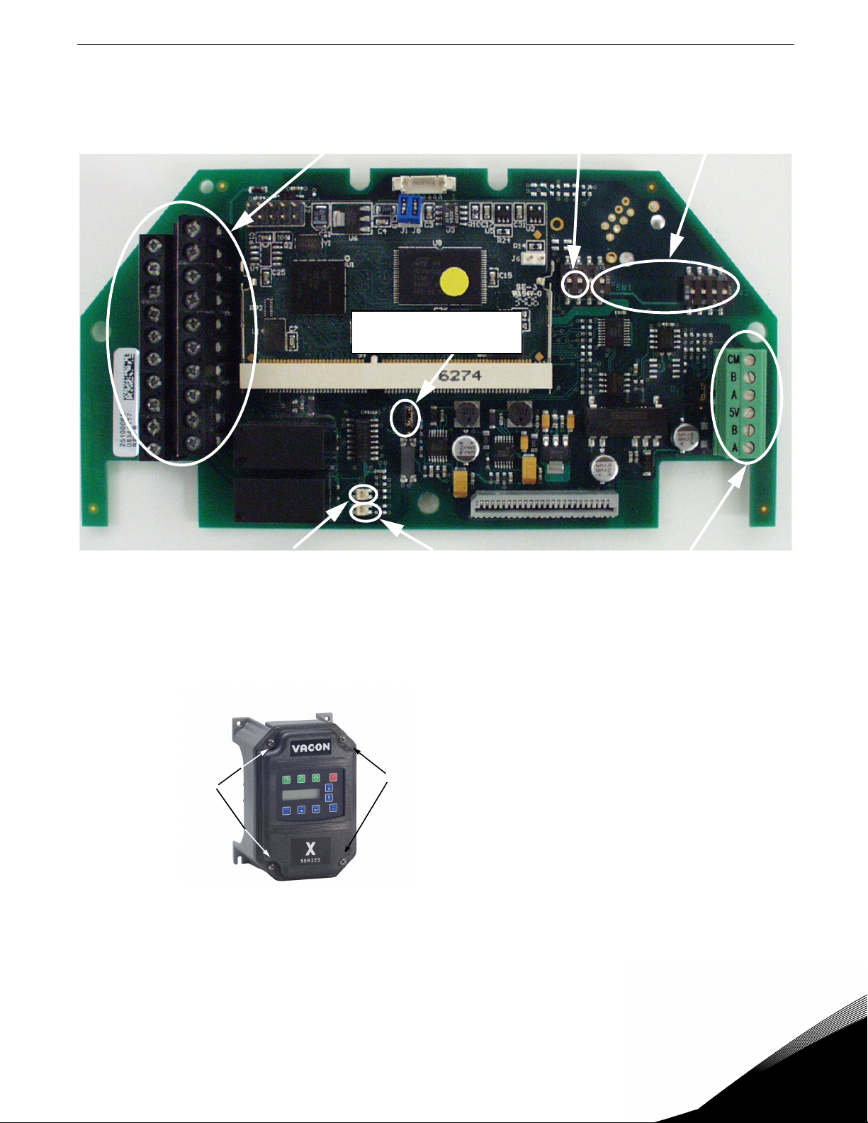
Figure 1 shows the layout of the option board and the location of important components on it.
Encoder / 115 VAC
Interface Terminals
Encoder Interface Power
Supply Selector
Switches 7-6;
7=not used
Switches 5-0; 6-0 used
for setting slave address
Module Status LED
Network Status LED
Profibus Terminal
Block
Figure 1: Option board layout
Before you can install the option board, you must first remove the drive cover.
Figure 2 shows the locations of the cover screws. The torque range for the X5 Size 1 cover is 18-26 in/lbs.
Cover screw locations
Figure 2: Cover assembly and screw locations
Cover screw locations
Email: usa@vacon.com • Fax 717-264-3115
Page 6
6 vacon X5PROFI01 Profibus Communication Option Board
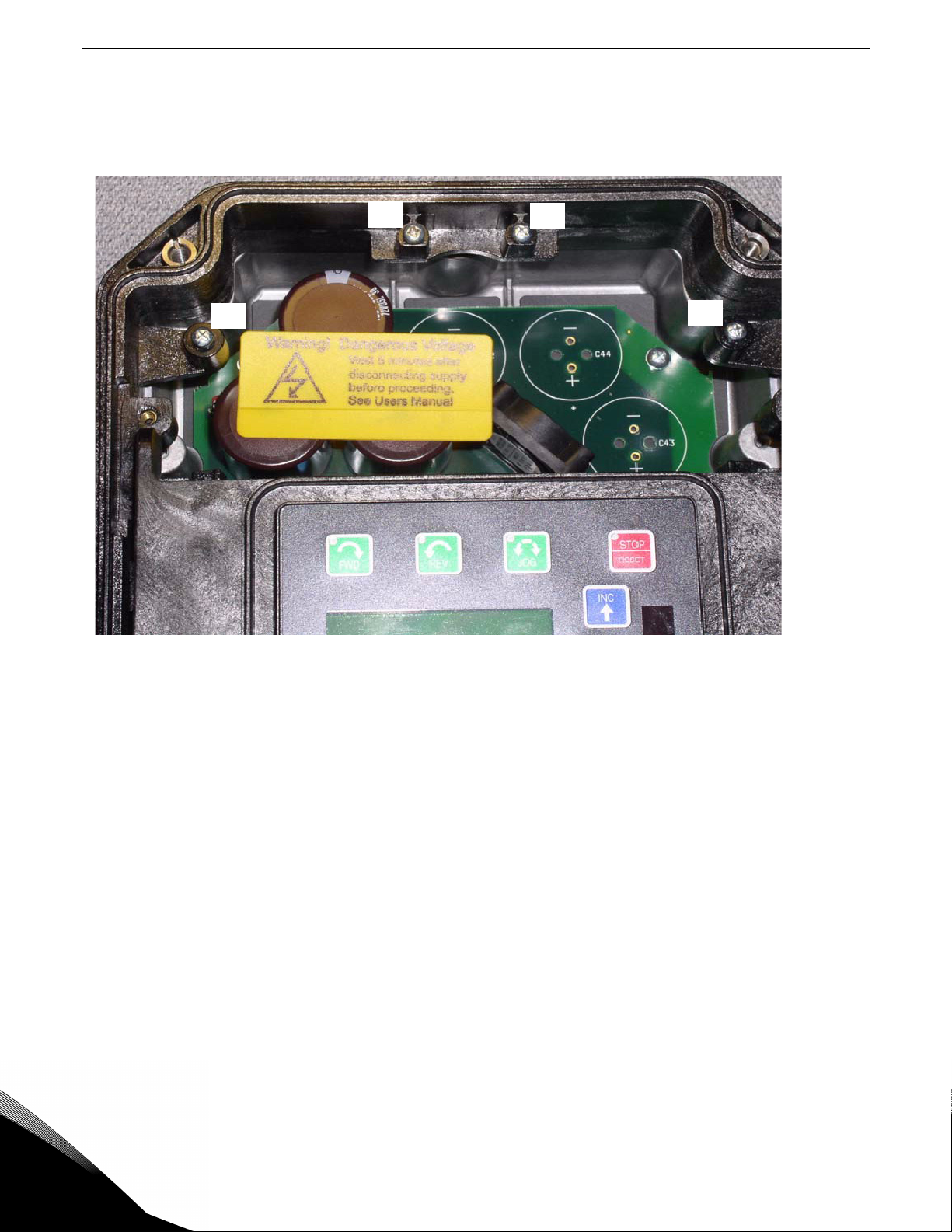
The option board is installed just above the control board in all configurations (a Size 1 unit is shown in Figure 3 for
reference). The screws labeled “A” must be removed from the X5; those labeled “B” need only to be loosened to
accept the board slot.
.
A
Figure 3: Option board mounting locations
B
B
A
Once the board is in place, tighten the screws to a maximum of 26 in-lbs.
24-hour support 1-877-822-6606
Page 7
X5PROFI01 Profibus Communication Option Board vacon 7
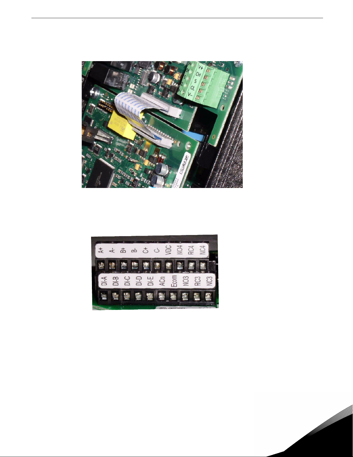
Next, install the flexible circuit to finish the interface to the control board. (Refer to Figure 4.) To install the flexible
ci rcuit, fi rst remove t he keypad frame (necessary in this size unit). The frame is attached with t wo screws in opposite
corners; the screws thread into fasteners in the plastic assembly. After the flexible circuit is installed, replace these
screws, limiting the installation torque to 12 in-lbs..
Figure 4: Flexible circuit interface to control board
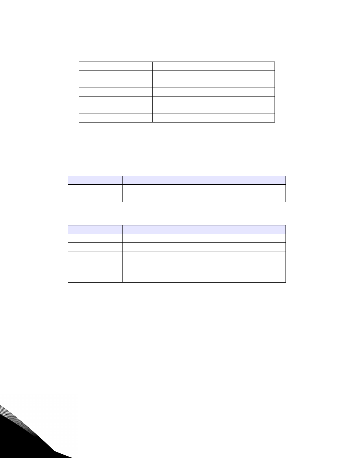
115 VAC Interface / Relay / Encoder Interface Terminals
.
Figure 5: 115 VAC interface / encoder terminals
The option kit includes five 115 VAC inputs, two additional programmable relays, and an encoder interface. The
details of the terminals on the board related to the 115 VAC interface and the encoder are shown in Table 1 on
page 8:
Email: usa@vacon.com • Fax 717-264-3115
Page 8

8 vacon X5PROFI01 Profibus Communication Option Board
Table 1: Encoder Interface Terminals
Terminal Description
115 VAC logic input; connect input to 115 VAC to activate.
DI-A
DI-B
DI-C
DI-D
DI-E
ACn The neutral connection for the 115 VAC control inputs
NO3
RC3
NC3
NO4
RC4
NC4
A+
A-
B+
B-
C+
C-
VDC
Ecom Signal common for the encoder interface
The programmable functionality of these inputs is controlled
by parameters 728, 729, 730, 731, and 732. Each of these
inputs can emulate the function of the FWD, REV, R/J, EN,
MOL, DI1, DI2, DI3, DI4, or DI5 input terminals on the X5
control board.
Refer to the X5 User’s Manual for more information (DPD
00089).
The third auxiliary relay.
The function of this relay is set by parameter 709.
Functionally, it is capable of each of the features outlined in
the X5 user manual under parameters 705-708.
Terminal NO3 is a normally-open contact; it closes when the
relay activates. NC3 is a normally-closed contact; it opens
when the relay activates. RC3 is the common terminal
associated with both contacts.
The ratings of these contacts are 115 VAC, 1 amp; and 230
VAC, 0.5 amp.
The fourth auxiliary relay.
The function of this relay is set by parameter 710.
Functionally, it is capable of each of the features outlined in
the X5 user manual under parameters 705-708.
Terminal NO4 is a normally-open contact; it closes when the
relay activates. NC4 is a normally-closed contact; it opens
when the relay activates. RC4 is the common terminal
associated with both contacts.
The ratings of these contacts are 115 VAC, 1 amp; and 230
VAC, 0.5 amp.
Channel A input from the encoder. Compatible with line
driver, open collector, or totem pole outputs from an
encoder. If it is an open collector or totem pole-type, encoder
outputs are used; connect the A- terminal to Ecom.
Channel B input from the encoder. Compatible with line
driver, open collector, or totem pole outputs from an
encoder. If it is an open collector or totem pole-type, encoder
outputs are used; connect the B- terminal to Ecom.
Channel C input from the encoder. Compatible with line
driver, open collector, or totem pole outputs from an
encoder. If it is an open collector or totem pole-type, encoder
outputs are used; connect the C- terminal to Ecom.
Power supply terminal for use with a customer-supplied
encoder. It can be either +12 VDC or +5 VDC based on the
position of the encoder interface power supply selector
shown in Figure 1 on page 5. Voltage regulation: +/- 5%;
maximum current available is 100 mA.
Note that the connections described in Table 1 work only when the encoder has an internal pull-up resistor on the
open collector. Alternatively, it might be preferable to pull the + channel high, and attach the open collector to the channel. For example, if using Channel A, A+ on the option board would be tied to VDC, and A- would be connected
to the open collector coming from the encoder. The advantage in this method is that no pull-up/down resistors are
needed; if the encoder has an internal pull-up, this does not affect anything.
24-hour support 1-877-822-6606
Page 9

X5PROFI01 Profibus Communication Option Board vacon 9
Specifications for the Encoder / 115 VAC Interface
Table 2: Encoder / 115 VAC Interface Specifications
Encoder Interface 115 VAC Interface
Speed regulation < 0.1 Hz (1) On state 90-140 VAC
Input frequency (max.) 100 kHz Off state < 10 VAC
Input voltage 10-24 VDC +/- 5% Input frequency 58-62 Hz
Suggested pull-up
resistor
Terminal block wire
limitations
(1) PID feedback plus optimal motor turning in SLV mode employed
5 VDC 500 ohms
24 VDC 3.3k ohms
12-24 AWG
On/off delay 30 ms maximum12 VDC 1k ohms
Terminal block wire
limitations
12-24 AWG
Setup and Use
The encoder interface is most effective if used in conjunction with the vector mode of operation. Refer to the X5
User’s Manual (Chapter 6) for information about using the vector mode. Three additional parameters are provided
to calibrate the encoder:
Parameter # Parameter Name Range Default Value
219 Encoder Pulses per Revolution 0-16383 1024
220 Encoder Filter Time 10-1000 ms 20 ms
221 Encoder Speed Protection 0-20.0% 0%
Parameter 219, Encoder Pulses per Revolution, can either be extracted from the encoder nameplate or the data
sheet supplied with it. Parameter 220, Encoder Filter Time, is used to filter the encoder signal in the event of noise.
Parameter 221 is for limiting the response of the drive, in the event of the loss of encoder signal.
Two other parameters are provided to allow more flexibility in encoder selection, and to improve PID application
usage:
Parameter # Parameter Name Range Default Value
Quadrature
223 EncoderType
224 Encoder Range 0-24000 rpm 0 rpm
or Single
Channel
Quadrature
Parameter 223, Encoder Type, allows the use of either quadrature or single-channel types of encoders.
Parameter 224, Encoder Range, improves PID application flexibility. This parameter should be used in situations
where the encoder feedback signal is not always directly proportional to the motor speed, for example, a winder
using an encoder mounted on an idler pulley feeding a winding spool. The PID may be attempting to maintain a
constant linear speed on the wound media, but as the diameter of the media on the spool changes, the motor
turning the spool needs to vary its speed to maintain the linear speed at the idler pulley.
When parameter 224 is set to 0, it is ignored, and the PID calculates the feedback percentage based on parameter
301, Maximum Frequency. When this parameter is set to a non-zero value, the PID uses instead Parameter 224’s
setting to calculate the feedback percentage.
Encoder feedback works similarly to an analog input as configured in parameters 850 (PID Configure), 851 (PID
Feedback), 852 (PID Prop Gain), 853 (PID Int Gain), and 859 (PID Derivative Gain). The “feed forward” options are
suggested for setting parameter 850. More specific details on each of the listed parameters can be found in the X5
User’s Manual (DPD 00089).
Email: usa@vacon.com • Fax 717-264-3115
Page 10

10 vacon X5PROFI01 Profibus Communication Option Board
The encoder interface can easily serve as one of the inputs to the X5’s Keeper Function (data logging). See the X5
User’s Manual for more information.
Both the Vmet and Imet output from the drive can be configured to indicate the status of the encoder. Parameters
700 (Vmet) and 702 (Imet) that relate to the setup and calibration of the Vmet and Imet outputs, both have selections
related to the status of the encoder input.
The Program Sequencer function can also key off the encoder’s home pulse. To make use of this function, the
encoder’s home pulse (1 pulse per revolution) must be connected to the C- input of the encoder board.
Encoder Interface Troubleshooting
Any problem with the encoder interface will result in an F37 fault. Four advanced fault codes are available to help
you determine whether you have an encoder calibration problem, or a defect. For more information on
troubleshooting, refer to the Troubleshooting chapter in the X5 User’s Manual. For information on setting
parameters, see Chapter 7 in the X5 User’s Manual.
Profibus Specifications and Connections
Following are the specifications for Profibus connections:
Table 3: Profibus Connection Specifications
Interface OPT-C3: pluggable connector (5.08 mm)
OPT-C5: 9-pin DSUB connector (female)
Profibus
Connections
Communications
Environment
Safety EN50178 standard
Data transfer method RS-485, half-duplex
Transfer cable Twisted pair (1 pair and shield)
Isolation 500 VDC
Profibus As described in document, “Profibus Profile for variable
speed drives, Profidrive”
PPO types 1, 2, 3, 4, 5
Baud rate 9.6 kbaud to 12 Mbaud
Addresses 2 to 126
Ambient operating temperature -10 degrees C...55 degrees C
Storage temperature -40 degrees C...60 degrees C
Humidity <95%, no condensation allowed
Altitude Max. 1000 m
Vibration 0.5 G at 9...200 Hz
Profibus Cable
Profibus devices are connected in a bus structure. A maximum of 32 stations (master or slaves) can be connected
in one segment. The bus is terminated by an active bus terminator at the beginning and end of each segment (see
24-hour support 1-877-822-6606
Page 11

X5PROFI01 Profibus Communication Option Board vacon 11
Figure 6). To ensure error-free operation, both bus terminations must always be powered. When more than 32
stations are used, repeaters (line amplifiers) must be used to connect the individual bus segments.
Master
Slave
Slave
Slave
Slave
Slave
R
Slave
32 / segment
Termination Resistor
Figure 6: Cabling and bus termination
R
max. 126 stations (4 segments)
R
Bus Repeater
Slave
32 / segment
Table 4 shows the line parameter specifications. The maximum cable length depends on the transmission speed
and cable type (see Table 5). The specified cable length can be increased using the repeaters. The use of more than
three repeaters in series is not recommended.
Table 4: Line Parameters
Parameter Line A Line B
Impedance
135...165 ohms
(3 to 20 MHz
Capacity < 30 pF/m < 60 pF/ m
Resistance < 110 ohms/km -
Wire gauge > 0.64 mm > 0.53 mm
Conductor area > 0.34 mm
2
100...130 ohms
(f > 100kHz)
> 0.22 mm
2
Table 5: Line Length for Different Transmission Speeds
Baud rate (kbit/s) 9.6 19.2 93.75 187.5 500 1500 3000-12000
Length line A (m) 1200 1200 1200 1000 400 200 100
Length line B (m) 1200 1200 1200 600 200 - -
The following cables can be used:
• Belden Profibus data cable 3079A
• Olflex Profibus cable 21702xx
• Siemens SINEC L2 LAN cable for Profibus 6XVI 830-0AH10
NOTE:
1. The minimum distance between power and bus cables is 30 cm.
2. A minimum cable length of 1 m between two stations is recommended.
The X5PROFI01 Profibus board is connected to the fieldbus through a 6-pin pluggable bus connector. (See Figure 1
on page 5 for the location of the bus connector.) Communication with the control board of the frequency converter
takes place through the flexible circuit applied last during the installation process.
Email: usa@vacon.com • Fax 717-264-3115
Page 12
12 vacon X5PROFI01 Profibus Communication Option Board
Profibus Terminals
Table 6 describes the Profibus terminal assignments:
Table 6: Profibus Terminal Block
Signal Connector Description
CM 1 Data ground (reference potential for 5V supply)
B 2 Receive / transmit data - plus
A 3 Receive / transmit data - minus
5V 4 5V supply voltage from option board
B 5 Receive / transmit data - plus
A 6 Receive / transmit data - minus
LED Indications
The Profibus option board includes two status LED status indicators, near the bottom center of the option board. See
Figure 1 on page 5 for the location of these LEDs on the board. The following tables explain the meaning of the status
LEDs:
Table 7: Top LED
If the LED is... This means...
OFF The Profibus option board is not activated.
Green (flashing) The Profibus option board has started up successfully.
Table 8: Bottom LED
If the LED is... This means...
OFF There is no external commucation (fieldbus side).
Green An active connection has been established with a Profibus network.
A Profibus network error has occurred. Check for the following:
Red
- Bus cable
- Possible error in configuration or parameter setting
- The master may be offline or shut down.
DIP Switches
The Profibus drop number is configured by the two banks of DIP switches located in the upper right corner of the
option board. (See Figure 1 on page 5 for an illustration.) The least significant bit is controlled by the rightmost
switch; the most significant bit by the second switch from the left on the left bank. The far leftmost switch on the left
bank (switch 7) has no function assigned to it.
The Profibus drop number value is a 7-bit binary number ranging from 0-127. Switches 6-0 set the slave address to
a value ranging from 0-127; however, the values 0, 1, and 127 are reserved by the protocol for non-slave devices.
Baud rate is set by the software, not by the DIP switches.
24-hour support 1-877-822-6606
Page 13
X5PROFI01 Profibus Communication Option Board vacon 13
Getting Started Using the Profibus Option Board
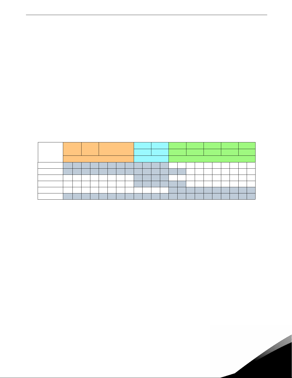
The X5 Profibus option implements six different I/O assemblies, as shown in Table 9. You can select the active input
and out assemblies, or PPOs (Parameter Process data Objects) by using parameter 879 (Profibus PPO) in the drive.
The default is PPO1.
The six PPOs provide varying combinations of three basic data types:
• Parameter data (orange)
• Control, Status, Reference, and Output (blue)
• Custom configurable drive parameters (green)
The first two data types are a basic implementation of the Profidrive profile. The third data type is custom, vendorspecific I/O which allows the user to read and write any five drive parameters.
In addition, you can select “Echo” in parameter 879. This mode provides four bytes of input data that simply “echo”
the four bytes of output data from the master. This mode is only useful for debugging purposes, and is not included
in Table 9. Note that parameter 879 is only included in X5_V0042 and later software.
I/O Assemblies
Table 9: Module Status LED
Output
Input
PPO1
PPO2
PPO3
PPO4
PPO5
PPO6
ID Ind Value
(Orange) (Blue) (Green)
CW REF FBW1 FBW2 FBW3 FBW4 FBW5
SW ACT FBR1 FBR2 FBR3 FBR4 FBR5
In this table, each blue-shaded block represents one byte of data. The abbreviations have the following meanings:
ID Parameter type and number
IND Parameter subindex
Value Parameter value
CW Control word
SW Status word
REF Frequency reference (in percent)
ACT Actual output frequency (in percent)
Email: usa@vacon.com • Fax 717-264-3115
Page 14

14 vacon X5PROFI01 Profibus Communication Option Board
Parameter Data: ID
ID Ind Value
CW REF FBW1 FBW2 FBW3 FBW4 FBW5
SW ACT FBR1 FBR2 FBR3 FBR4 FBR5
ID Ind Value
ID byte 1 ID byte 2
1514131211109876543210
Request / Response type SM Parameter Number ( = Vacon ID number)
SM: Spontaneous bit (not used)
Request / Response types
Request Function
0 No request
1 Read parameter value (word)
2 Write parameter value (word)
Response Function
0 No response
1 Parameter value ready (word)
7 Request rejected (+ fault code)
Fault numbers if response = 7:
Fault
Number
0 Illegal parameter
1
2 Parameter value is out of limits
17
18 Other fault
101 Unknown request type
Description
Parameter is read-only (actual
values)
Request temporarily rejected (ex:
can be changed only for STOP
state)
24-hour support 1-877-822-6606
Page 15

X5PROFI01 Profibus Communication Option Board vacon 15
Parameter Data: Index
ID Ind Value
Not in use
Parameter Data: Data Value
ID Ind Value
Data word 1 (HIGH Data word 2 (LOW)
byte 0 byte 1 byte 2 byte 3
In writing mode, the data to be written is placed in the field, “Data word 2.”
In reading mode, the answer is in the field, “Data word 2.”
“Data word 1” is normally zero.
Email: usa@vacon.com • Fax 717-264-3115
Page 16

16 vacon X5PROFI01 Profibus Communication Option Board
Control and Reference: Control Word (CW)
ID Ind Value
Bit Description
Bit No. Value = 0 Value = 1
0STOP 1 (by ramp)ON 1
1STOP 2 (by coast)ON 2
2STOP 3 (by ramp)ON 3
3 RUN DISABLE ENABLE
4 No action START
5 No action START
6 No action START
7 No action FAULT RESET (0 >/- 1
8 No action No action
9 No action No action
10 Disable Profibus control Enable Profibus control
11 No action No action
12 No action No action
13 No action No action
14 No action No action
15 No action No action
CW REF FBW1 FBW2 FBW3 FBW4 FBW5
SW ACT FBR1 FBR2 FBR3 FBR4 FBR5
Control and Reference: Status Word (SW)
ID Ind Value
Bit No. Value = 0 Value = 1
0 Not Ready (initial) READY 1
1Not Ready READY 2
2 DISABLE ENABLE
3 NO FAULT FAULT ACTIVE
4 STOP 2 NO STOP 2
5 STOP 3 NO STOP 3
6 START ENABLE START DISABLE
7 No warning Warning
8 Reference not equal to actual value Reference equals actual value
9 Fieldbus control OFF Fieldbus control ON
10 Not used Not used
11 Not used Not used
12 FC stopped Running
13 FC not ready FC Ready
14 Not used Not used
15 Not used Not used
CW REF FBW1 FBW2 FBW3 FBW4 FBW5
SW ACT FBR1 FBR2 FBR3 FBR4 FBR5
Bit Description
24-hour support 1-877-822-6606
Page 17

X5PROFI01 Profibus Communication Option Board vacon 17
Profidrive State Machine:
Fault
Set CW Bit0=0
STOP1 (ramp
Set CW Bit3=0
RUN
DISABLE(Coast)
Power On
INIT
SW Bit 6 = 1
Set CW bit0=0, Set CW1=0
STOP
SW Bit 6 = 0
Set CW bit1=1, bit2=1, bit10=1
READY1
SW Bit 0 = 1
Set CW bit0=1, bit10=1
READY2
SW Bit 1 = 1
Set CW=0
Reset Fault
CW Bit7=1
Set CW=0
Set CW=0
FAULT(?)
Set CW Bit1=0
STOP2(Coast)
Set CW Bit2=0
STOP3(Ramp)
Set CW bit3=1, bit10=1
ENABLED
SW Bit 2 = 1
Set CW bit4=1, bit5=1,
bit6=1, bit10=1
RUNNING
Set CW=0
Set CW=0
Note: The Enable
Profibus control bit of
the Profidrive control
word sets the SLC and
SLF bits of the X5 CW.
The Fieldbus control on
bit of the Profidrive
status word = SLC&&SLF
Email: usa@vacon.com • Fax 717-264-3115
Page 18

18 vacon X5PROFI01 Profibus Communication Option Board
Reference and Actual Frequency:
ID Ind Value
CW
SW
REF FBW1 FBW2 FBW3 FBW4 FBW5
ACT FBR1 FBR2 FBR3 FBR4 FBR5
This is the reference 1 to the frequency converter. Used normally as speed reference, the allowed scaling is -10,000
to 10,000. In the application, the value is scaled in percentage of the frequency area between set minimum and
maximum frequency.
-10000 = 100.00% (Direction reverse)
0 = 0.00% (Direction forward)
10000 = 100.00% (Direction forward)
Configurable FBus Parameters:
ID Ind Value
CW REF
SW ACT
FBW1 FBW2 FBW3 FBW4 FBW5
FBR1 FBR2 FBR3 FBR4 FBR5
The Fieldbus read and write parameters allow you to set up custom I/O using any drive parameters. The output
assembly permits you to write to any five parameters, and the input assembly permits you to read any five
parameters. The FBus Write parameters are set up using parameters 890-894, and the FBus Read parameters are
set up using parameters 880-884.
For example, if PPO2 was selected, and you wanted to write to the drive parameter Accel Time 1 (drive parameter
402) using field “FBW1” of the output assembly, you would set drive parameter 890 to a value of 402. Likewise, if you
wanted to read parameter “Output Current” (drive parameter 104) using field “FBR1” of the input assembly, you
would set drive parameter 880 to a value of 104.
24-hour support 1-877-822-6606
Page 19

X5PROFI01 Profibus Communication Option Board vacon 19
Examples of Profibus requests
Example 1: Read drive parameter 302 (Maximum Frequency)
Command Master-Slave:
ID 112E hex 1 - Read parameter value
12E hex = Parameter 302 dec (e.g. maximum frequency)
IND 0000 hex 0000 - no meaning
VALUE 0000 0000 hex 0000 0000 - no meaning
Answer Slave-Master:
ID 112E hex 1 - Parameter value ready
12E hex = Parameter 302 ( = maximum frequency)
IND 0000 hex 0000 - no meaning
VALUE
Email: usa@vacon.com • Fax 717-264-3115
0000
258 hex
0000 - high word (no meaning)
258 = 600 dec (60.0 Hz)
Page 20

20 vacon X5PROFI01 Profibus Communication Option Board
Example 2: Send run command to drive, and provide a reference of 50.00%
Command Master-Slave:
ID 0000 hex No parameter request
IND 0000 hex 0000 - no meaning
VALUE 0000 0000 hex 0000 0000 - no meaning
CW 047F hex
REF 1388 hex
04 7F - start command (see control word and state machine
definitions)
5000 dec - speed ref 50.00% (= 30.0 Hz if the parameter
minimum frequency is 0 Hz and maximum frequency is 60 Hz)
Answer Slave-Master:
ID 0000 hex 0000 - no meaning
IND 0000 hex 0000 - no meaning
VALUE
SW
ACT 1388 hex
24-hour support 1-877-822-6606
0000
0000
0013
hex
0000 0000 (no meaning)
0013 - frequency converter status (see status word and state
machine definitions)
Current speed 50.00% (= 30.00 Hz if the parameter minimum
frequency is 0 Hz and the maximum frequency is 60 Hz)
Page 21

X5PROFI01 Profibus Communication Option Board vacon 21
Email: usa@vacon.com • Fax 717-264-3115
Page 22

head office and production:
Vaasa
Vacon Plc
Runsorintie 7
65380 Vaasa
firstname.lastname@vacon.com
telephone: +358 (0)201 2121
fax: +358 (0)201 212 205
production:
Suzhou, China
Vacon Suzhou Drives Co. Ltd.
Building 11A
428# Xinglong Street, SIP
Suchun Industrial Square
Suzhou 215126
telephone: + 86 512 62836630
fax: + 86 512 62836618
Naturno, Italy
Vacon S.R.I
Via Zone Industriale, 11
39025 Naturno
sales companies and representative offices:
production:
Chambersburg, USA
3181 Black Gap Road
Chambersburg, PA 17202
TB Wood's (India) Pvt. Ltd.
#27, 'E' Electronics City
Hosur Road
Bangalore - 560 100
India
Tel. +91-80-30280123
Fax. +91-80-30280124
finland
Helsinki
Vacon Plc
Äyritie 8
01510 Vantaa
telephone: +358 (0)201 212 600
fax: +358 (0)201 212 699
Tampere
Vacon Plc
Vehnämyllynkatu 18
33580 Tampere
telephone: +358 (0)201 2121
fax: +358 (0)201 212 750
australia
Vacon Pacific Pty Ltd
5/66-74, Micro Circuit
Dandenong South, VIC 3175
telephone: +61 (0)3 9238 9300
fax: +61 (0)3 92389310
austria
Vacon AT Antriebssysteme GmbH
Aumühlweg 21
2544 Leobersdorf
telephone: +43 2256 651 66
fax: +43 2256 651 66 66
belgium
Vacon Benelux NV/SA
Interleuvenlaan 62
3001 Heverlee (Leuven)
telephone: +32 (0)16 394 825
fax: +32 (0)16 394 827
brazil
Vacon Brazil
Alameda Mamoré, 535
Alphaville - Barueri -SP
Tel. +55 11 4166-5707
Fax. +55 11 4166-5567
canada
Vacon Canada
221 Griffith Road
Stratford, Ontario N5A 6T3
telephone: +1 (519) 508-2323
fax: +1 (519) 508-2324
china
Vacon Suzhou Drives Co. Ltd.
Beijing Branch
A528, Grand Pacific Garden Mansion
8A Guanghua Road
Beijing 100026
telephone: + 86 10 51280006
fax: +86 10 65813733
czech republic
Vacon s.r.o.
Kodanska 1441/46
110 00 Prague 10
telephone: +420 234 063 250
fax: +420 234 063 251
france
Vacon France
ZAC du Fresne
1 Rue Jacquard - BP72
91280 Saint Pierre du Perray CDIS
telephone: +33 (0)1 69 89 60 30
fax: +33 (0)1 69 89 60 40
germany
Vacon GmbH
Gladbecker Strasse 425
45329 Essen
telephone: +49 (0)201 806 700
fax: +49 (0)201 806 7099
Vacon OEM Business Center GmbH
Industriestr. 13
51709 - Marienheide
Germany
Tel. +49 02264 17-17
Fax. +49 02264 17-126
india
Vacon Drives & Control Plc
Plot No 352
Kapaleeshwar Nagar
East Coast Road
Neelangarai
Chennai-600041
Tel. +91 44 244 900 24/25
italy
Vacon S.p.A.
Via F.lli Guerra, 35
42100 Reggio Emilia
telephone: +39 0522 276811
fax: +39 0522 276890
the netherlands
Vacon Benelux BV
Weide 40
4206 CJ Gorinchem
telephone: +31 (0)183 642 970
fax: +31 (0)183 642 971
norway
Vacon AS
Bentsrudveien 17
3080 Holmestrand
telephone: +47 330 96120
fax: +47 330 96130
romania
Vacon Romania - Reprezentanta
Cuza Voda 1
400107 Cluj Napoca
Tel. +40 364 118 981
Fax. +40 364 118 981
russia
ZAO Vacon Drives
Ul. Letchika Babushkina 1,
Stroenie 3
129344 Moscow
telephone: +7 (495) 363 19 85
fax: +7 (495) 363 19 86
ZAO Vacon Drives
2ya Sovetskaya 7, office 210A
191036 St. Petersburg
telephone: +7 (812) 332 1114
fax: +7 (812) 279 9053
slovakia
Vacon s.r.o. (Branch)
Seberiniho 1
821 03 Bratislava
Tel. +421 243 330 202
Fax. +421 243 634 389
spain
Vacon Drives Ibérica S.A.
Miquel Servet, 2. P.I. Bufalvent
08243 Manresa
telephone: +34 93 877 45 06
fax: +34 93 877 00 09
sweden
Vacon AB
Anderstorpsvägen 16
171 54 Solna
telephone: +46 (0)8 293 055
fax: +46 (0)8 290 755
thailand
Vacon South East Asia
335/32 5th-6th floor
Srinakarin Road, Prawet
Bangkok 10250
Tel. +66 (0)2366 0768
ukraine
Vacon Drives Ukraine (Branch)
42-44 Shovkovychna Str.
Regus City Horizon Tower
Kiev 01601, Ukraine
Tel. +380 44 459 0579
Fax +380 44 490 1200
united arab emirates
Vacon Middle East and Africa
Block A, Office 4A 226
P.O.Box 54763
Dubai Airport Free Zone
Dubai
Tel. +971 (0)4 204 5200
Fax: +971 (0)4 204 5203
united kingdom
Vacon Drives (UK) Ltd.
18, Maizefield
Hinckley Fields Industrial Estate
Hinckley
LE10 1YF Leicestershire
telephone: +44 (0)1455 611 515
fax: +44 (0)1455 611 517
united states
Vacon, Inc.
3181, Black Gap Road
Chambersburg, PA 17202
telephone: +1 (877) 822-6606
fax: +1 (717) 267-0140
 Loading...