

Page 1
Data Sheet
Pressure operated water valve
Type WVFX and WVS
Opens on rising condensing pressure
Pressure operated water valves types WVFX
and WVS are used for regulating the ow of
water in refrigeration plants with water-cooled
condensers.
The pressure operated water valves give
modulating regulation of the condensing
pressure within dened limits during operation.
When the refrigeration plant is stopped, the
cooling water ow is shut o automatically.
Pressure operated water valves can be used
with ammable refrigerants. Double sealing
between the refrigerant and the water line
ensures that in case the bellows damage and
the refrigerant leak, it cannot enter into the
water. This severely limits the safety
implications. It means that the valve can be
used together with a double walled heat
exchanger and water circuit in such a system
does not need to be considered as a part of the
installation for ammable refrigerants
(EN378-1:2008, clause 4.4.2.2).
Features
• Media: Fresh water and Neutral brine
• Needs no power supply – self acting
• Opens on rising condensing pressure
• Complete ow range from 1.4 – 300 m3/h
• Low ow version of WVFX – 0,63 m3/h,
(available on request)
• Insensitive to dirt
• WVFX 10 – 25 are available in stainless steel
housing
• Suitable for ammable refrigerants
• May be used in the following EX range:
Category 3 (Zone 2)
AI250886497511en-001401
Page 2
Danfoss
3N162
5
7
5
9
6
4
3
2
1
8
6
3
10
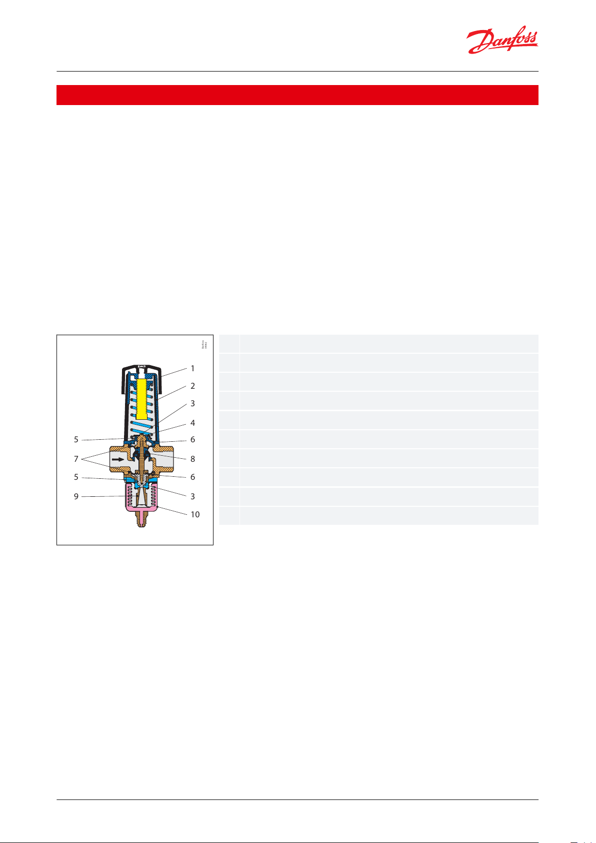
12345678910Handwheel
Spring housing
Spindle guide
Spring retainer
O-ring
Guide bush
Diaphragm
Valve cone
Thrust pad
Bellows element
Pressure operated water valve, Type WVFX and WVS
Functions
Condensing pressure impulses are transmitted via the bellows element to the valve cone so that the valve – even at
very small pressure variations – is able to adapt the quantity of water required by the condenser.
The valves are pressure-relieved in such a way that a variation in the water pressure will not aect their setting.
To protect the refrigeration plant against high head pressures in the event that the water supply to the condenser
fails, a safety switch type KP or RT should be tted on the high pressure side.
Water side connections are internal BSP and the compressor discharge side connection is
1
⁄4 in. / 6 mm are.
The valve body WVFX 10 – 25 is made of hot-stamped brass and for WVFX 32 – 40 of cast iron. WVFX 15, WVFX 20
and WVFX 25 can also be supplied in stainless steel housing.
All metal external valve parts are surface-treated to resist corrosion from condensate, etc.
It is possible to order reverse acting WVFX valve, which opens on refrigerant pressure decrease.
Reverse acting valve are mostly used in bypass lines and heat pump applications.
Figure 1: Design / Function for WVFX 10 – 25
The valve cone (8) is a brass plate with a vulcanized layer of articial rubber to form an elastic seal against the valve
seat. The valve is externally sealed by the diaphragms (7).
The top and bottom of the valve plate holder are extended by a guide that is tted with O-rings (5) to ensure the
internal operating parts move correctly. These O-rings, tted in conjunction with the diaphragms, also provide extra
protection against external leakage.
The valve seat is made of stainless steel and is pressed to the valve body.
The spring housing (2) is of aluminium and has a guide slot for the spring holder that is extended in the form of an
indicating pointer. An associated indicator label is riveted to the housing and is graduated from 1 – 5.
© Danfoss | Climate Solutions | 2021.02 AI250886497511en-001401 | 2
Page 3
Danfoss
3N164-j
1
2
3
4
8
5
7
8
9
10
11
6
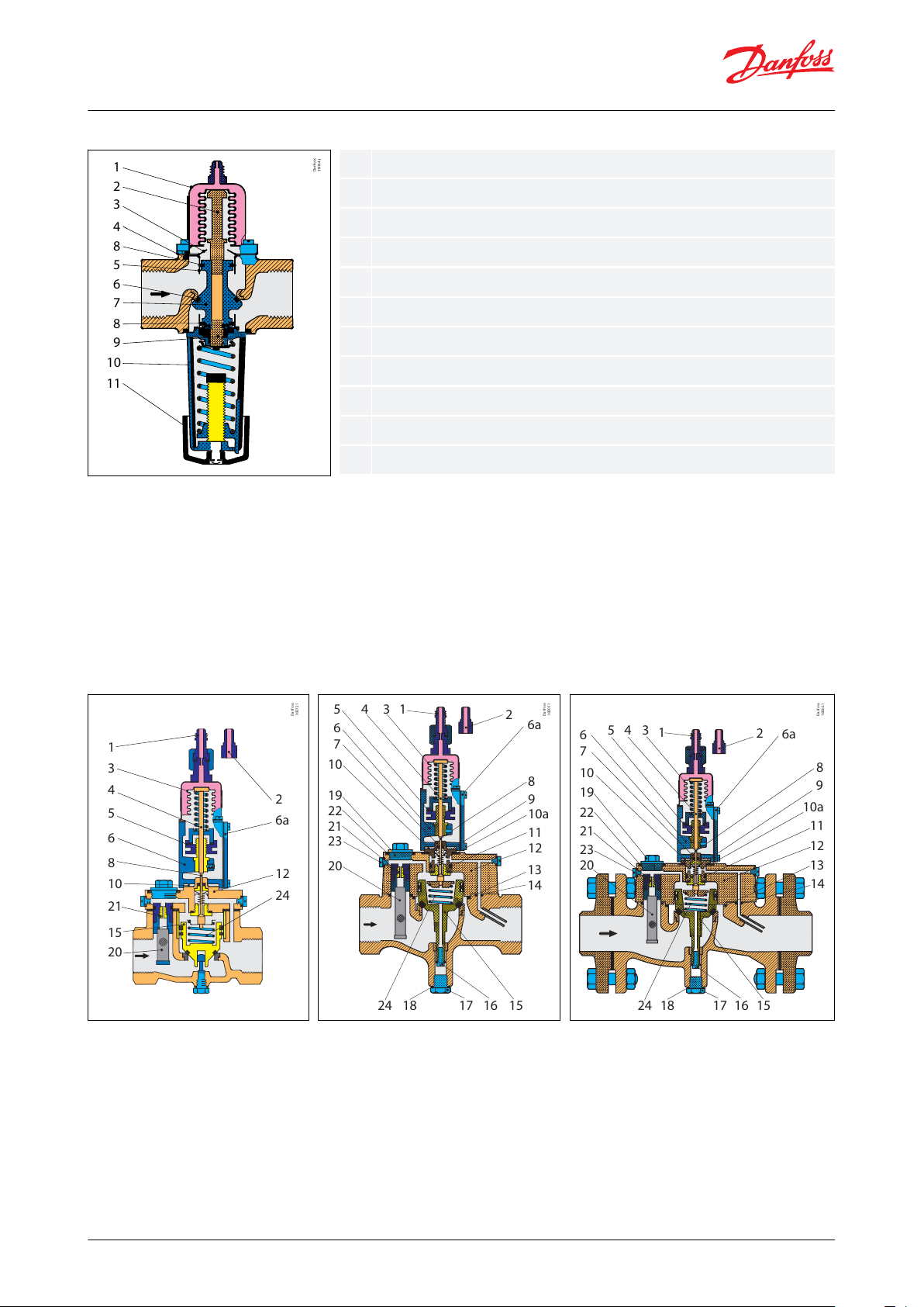
1234567891011
Bellows element
Upper pressure spindle
Top plate
Guide bush gland
Guide bush
T-ring
Valve cone
O-ring
Lower pressure spindle
Spring housing
Handwheel
Danfoss
16D721
2
6a
12
24
20
15
21
10
8
6
5
4
3
1
Danfoss
16D051
2
6a
8
9
10a
11
12
13
14
20
23
21
22
19
10
7
6
5
4 3 1
24 18 17 16 15
Danfoss
16D021
1
345
6
7
10
19
22
21
23
20
24 18 17 16 15
14
13
12
11
10a
9
8
6a
2
Pressure operated water valve, Type WVFX and WVS
Figure 2: Design / Function for WVFX 32 – 40
The valve cone (7) is made of brass with a T-ring (6) of articial rubber forming a exible seal against the valve seat.
The O-rings (8) are external seals for the cooling water.
The valve cone guide bushes (5) are specially treated to counteract lime deposits from the cooling water inside the
cylinder, and also to reduce friction in the valve to a minimum.
The valve seat is made of stainless steel and is pressed to the valve body.
The spring housing (2) is of aluminium and has a guide slot for the spring holder that is extended in the form of an
indicating pointer.
Figure 3: WVS 32
Figure 4: WVS 40
Figure 5: WVS 50 – 100
© Danfoss | Climate Solutions | 2021.02 AI250886497511en-001401 | 3
Page 4

1
2
34566a78910
10a1112131415161718
1920212223
24
Pressure connection (are
nipple)
Pressure connection (weld
nipple)
Bellows element
Push rod
Regulating nut
Spring housing
Cover
Pilot assembly
Spindle for pilot cone
Teon sleeves
Insulating gasket
Gasket
O-ring
Valve cover
O-ring
O-ring
Servo piston
Bottom screw
Drain plug
Gasket
Strainer assembly, complete
Self-cleaning strainer
assembly
Pilot orice
Gasket
O-ring
Servo spring
Pressure operated water valve, Type WVFX and WVS
WVS 32 – 40 valves have internal BSP connections, while WVS 50 – 100 can be supplied with either BSP connections
or weld anges.
Connection to the plant condenser can be made by copper tube or steel tube, the valves being supplied with both a
are nipple for
1
⁄4 in. (6 mm) copper tube and a weld nipple for ø6 mm / ø10 mm steel tube.
1. Main valve with servo piston
The main valve body is made of cast iron with a pressed-in bronze seat. The servo piston is of gun metal and has a
sleeve and a proled rubber seal ring.
2. Pilot valve
The pilot valve is made of gun metal, the pilot cone and seat of stainless steel and the pilot orice of brass. These
materials are particularly resistant to water corrosion. However, the valve is not resistant to sea water.
The strainer ahead of the pilot orice is made of nickel gauze.
The degree of opening of the pilot valve (which corresponds to the increase in condensing pressure above the set
opening pressure) determines the degree of opening of the main valve and thereby amount of the water ow.
3. Bellows unit with connection to condenser
The bellows unit is made of aluminium and corrosion-proofed steel.
© Danfoss | Climate Solutions | 2021.02 AI250886497511en-001401 | 4
Page 5
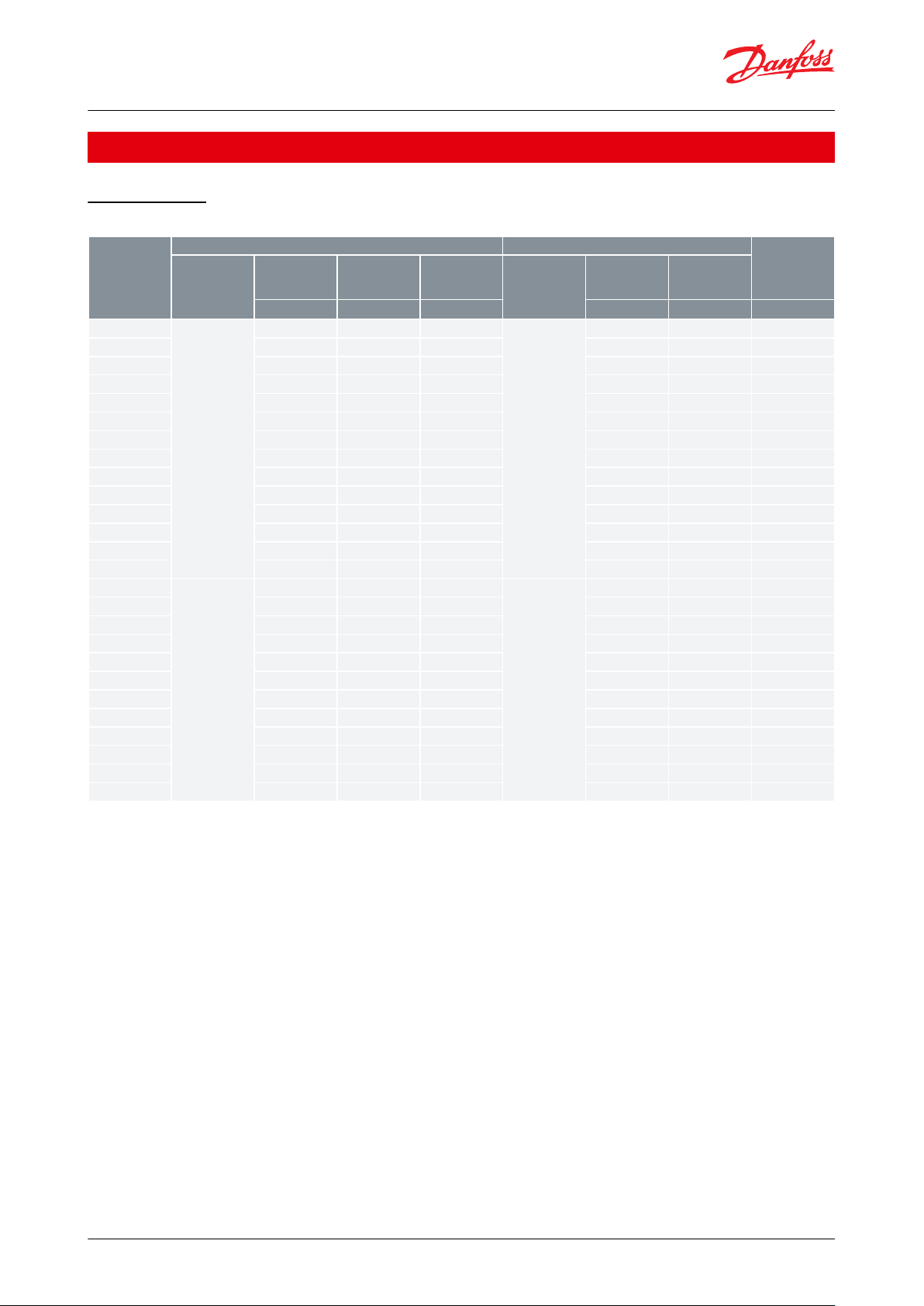
Type
Condenser side
Liquid side
Kv value
(1)
Refrigerant
Control press.
adjustable
opening press.
Max. working
pressure
PS/MWP
Max. test pres‐
sure Pe
Media
Max. working
pressure
PS/MWP
Max. test pres‐
sure Pe
[bar]
[bar]
[bar]
[bar]
[bar]
[m3/h]
WVFX 10
R22, R134a,
R290, R404A,
R407A, R407C,
R407F, R407H,
R410A
(4)
, R422B,
R422D, R448A,
R449A, R449B,
R450A, R452A,
R454A, R454C,
R455A, R507A,
R513A, R515B,
R516A, R600,
R600a, R1234yf,
R1270
3.5 – 16.0
26.4
29.0
Fresh water,
neutral brine,
sea water
(3)
16241.4
WVFX 10
(2)
4.0 – 23.0
26.4
29.01624
1.4
WVFX 10
15.0 – 29.0
45.2
60.01624
1.4
WVFX 15
3.5 – 16.0
26.4
29.01624
1.9
WVFX 15
(2)
4.0 – 23.0
26.4
29.01624
1.9
WVFX 15
15.0 – 29.0
45.2
60.01624
1.9
WVFX 20
3.5 – 16.0
26.4
29.01624
3.4
WVFX 20
(2)
4.0 – 23.0
26.4
29.01624
3.4
WVFX 20
15.0 – 29.0
45.2
60.01624
3.4
WVFX 25
3.5 – 16.0
26.4
29.01624
5.5
WVFX 25
(2)
4.0 – 23.0
26.4
29.01624
5.5
WVFX 25
15.0 – 29.0
45.2
60.01624
5.5
WVFX 32
4.0 – 17.0
24.1
26.51010
11.0
WVFX 40
4.0 – 17.0
24.1
26.51010
11.0
WVS 32
R22, R134a,
R290, R404A,
R407A, R407C,
R407F, R407H,
R410A
(4)
, R422B,
R422D, R448A,
R449A, R449B,
R450A, R452A,
R507A, R513A,
R600, R600a,
R717
(5)
, R1270
2.2 – 19.0
26.4
29.0
Fresh water,
neutral brine
101612.5
WVS 32
15.0 – 29.0
45.2
60.01016
12.5
WVS 40
2.2 – 19.0
26.4
29.01016
21.0
WVS 40
15.0 – 29.0
45.2
60.01016
21.0
WVS 50
2.2 – 19.0
26.4
29.01016
32.0
WVS 50
15.0 – 29.0
45.2
60.01016
32.0
WVS 65
2.2 – 19.0
26.4
29.01016
45.0
WVS 65
15.0 – 29.0
45.2
60.01016
45.0
WVS 80
2.2 – 19.0
26.4
29.01016
80.0
WVS 80
15.0 – 29.0
45.2
60.01016
80.0
WVS 100
2.2 – 19.0
26.4
29.01016
125.0
WVS 100
15.0 – 29.0
45.2
60.01016
125.0
Pressure operated water valve, Type WVFX and WVS
Product specication
Technical data
Table 1: Technical data
(1)
(1)
The Kv value is the ow of water in [m3/h] at a pressure drop across valve of 1 bar, ρ = 1000 kg/m3.
The Kv value is the ow of water in [m3/h] at a pressure drop across valve of 1 bar, ρ = 1000 kg/m3.
(2)
(2)
Fully open valve requires 33% higher pressure than a WVFX, range 3.5 – 16 bar.
Fully open valve requires 33% higher pressure than a WVFX, range 3.5 – 16 bar.
(3)
(3)
WVFX 15, WVFX 20 and WVFX 25 with stainless steel housing only.
WVFX 15, WVFX 20 and WVFX 25 with stainless steel housing only.
(4)
(4)
High pressure refrigerants version (45,2 MWP) only
High pressure refrigerants version (45,2 MWP) only
(5)
(5)
WVS, WVFX 10 – 25 and WVO with are connection only; versions with capillary tube or with solder connections are not compatible with R717.
WVS, WVFX 10 – 25 and WVO with are connection only; versions with capillary tube or with solder connections are not compatible with R717.
WVFX 32 and WVFX 40 are not compatible with R717
WVFX 32 and WVFX 40 are not compatible with R717
WVFX is evaluated for R290, R454A, R454C, R455A, R600, R600a, R1234yf, R1270 by ignition source assessment in
accordance with standard EN ISO80079-36. Flare connections are only approved for A1 and A2L refrigerants.
WVS is evaluated for R290, R600, R600a, R1270 by ignition source assessment in accordance with standard EN
ISO80079-36. Flare connections are only approved for A1 and A2L refrigerants.
For complete list of approved refrigerants, visit store.danfoss.com and search for individual code numbers, where
refrigerants are listed as part of technical data
WVFX 10 – 40 are direct actuated valves. WVS 32 – 100 are servo-operated valves.
Media temperature range
• WVFX 10 – 25: -25 – 130 °C
• WVFX 32 – 40: -25 – 90 °C
• WVS: -25 – 90 °C
© Danfoss | Climate Solutions | 2021.02 AI250886497511en-001401 | 5
Page 6
[bar]
Danfoss
16D851
[m /h]
3
Standard servo spring type WVS
Special servo spring type WVS
Type
∆p oset [bar]
WVFX 10
2.0
WVFX 15
2.5
WVFX 20
3.0
WVFX 25
3.5
WVFX 32 – 40
3.0
WVS 32
0.6
WVS 40
0.7
WVS 50 – 80
0.8
WVS 100
0.9
Pressure operated water valve, Type WVFX and WVS
If a WVS is required with an opening dierential pressure of 1 – 10 bar, the valve servo spring must be replaced. See
Ordering.
Opening dierential pressure
• WVFX 10 – 25: max. 10 bar
• WVFX 32 – 40: max. 10 bar
• WVS 32 – 40: min. 0.5 bar; max. 4 bar
• WVS 50 – 100: min. 0.3 bar; max. 4 bar
Below 20% of max. capacity the WVS will act as an on-o regulator.
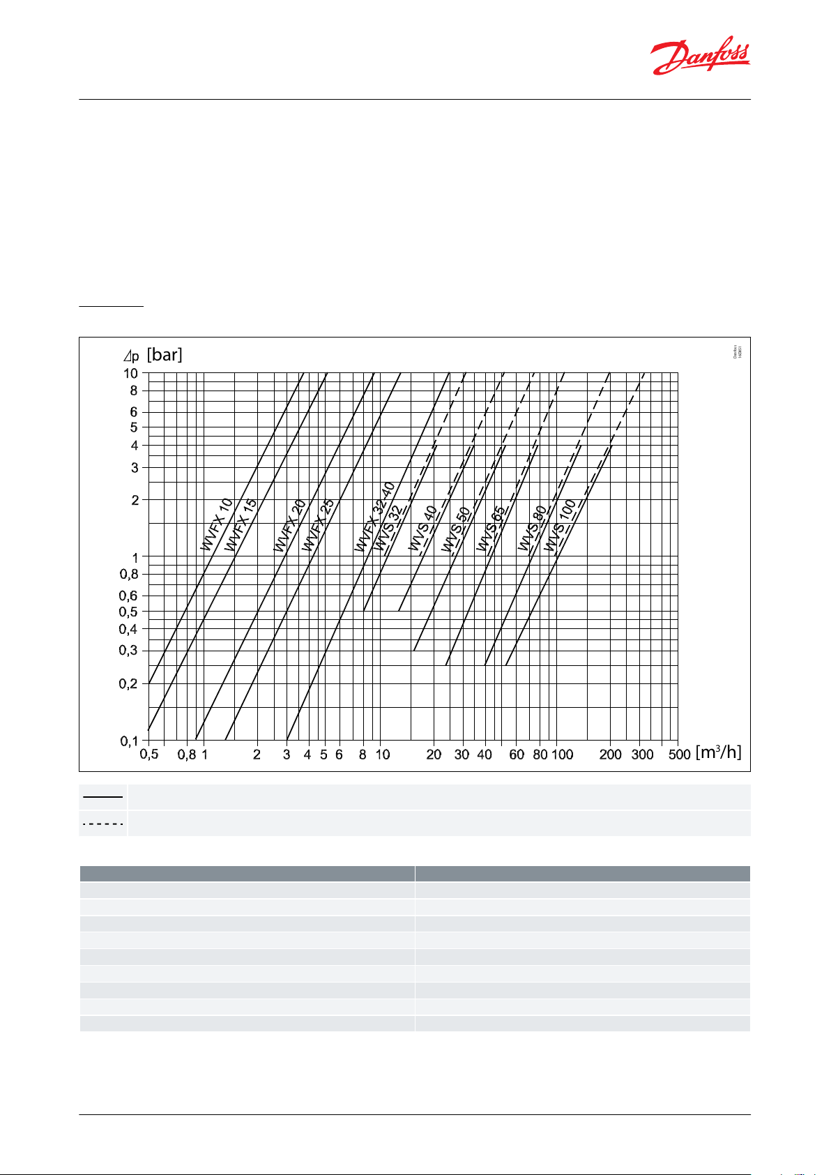
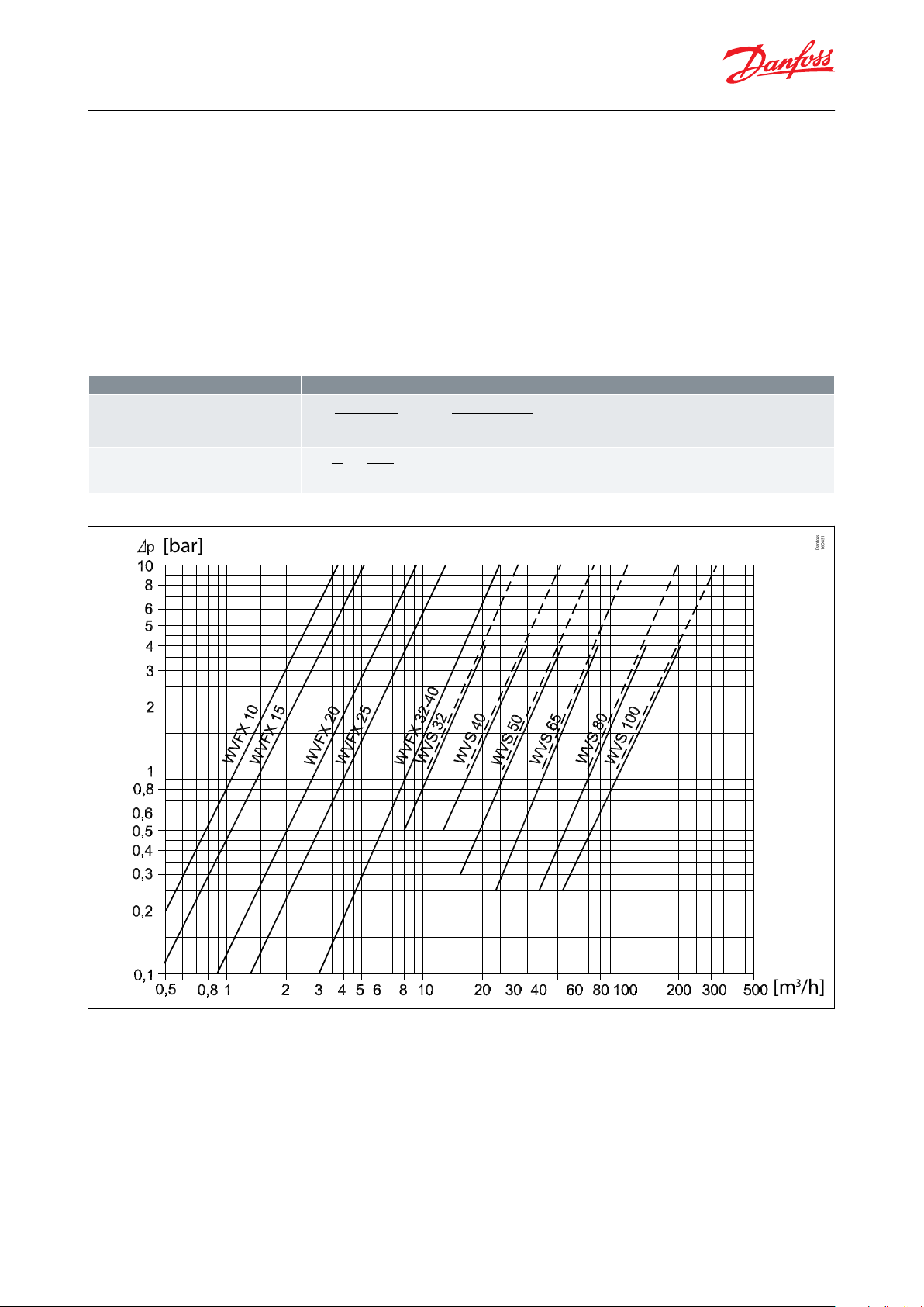
Capacity
Figure 6: Capacity
Table 2: Water Valves Oset – rise in condensing pressure
© Danfoss | Climate Solutions | 2021.02 AI250886497511en-001401 | 6
Page 7
C
P
100%
85%
0%
∆p
CPΔp
Water capacity
Condensing pressure
Δp oset
Type
∆p
oset [bar]
WVFX 10
2.0
WVFX 15
2.5
WVFX 20
3.0
WVFX 25
3.5
WVFX 32 – 40
3.0
WVS 32
0.6
WVS 40
0.7
WVS 50 – 80
0.8
WVS 100
0.9
Pressure operated water valve, Type WVFX and WVS
The capacity curves show the capacities of individual valves (water quantity in [m3/h]) depending on the pressure
drop across valves. The capacities given apply at 85% valve opening and are obtained with the following oset (rise
in condensing pressure).
Installation
WVS and WVFX 32, WVFX 40 is to be tted in the cooling water inlet with ow in the direction of the arrow and with
the bellows element facing upwards. Horizontal mounting is a must.
WVFX 10, WVFX 15 and WVFX 25 can be mounted in any position. Horizontal mounting is not required.
Sizing
When sizing and selecting water regulating valves it is most important to ensure that the valve at any time is able to
give the necessary quantity of cooling water.
To select a suitable size of valve it is necessary to know the precise amount of cooling required.
On the other hand, to avoid the risk of unstable regulation (hunting) the valve should not be oversized. In general,
the aim should be to select the smallest valve capable of giving the required ow.
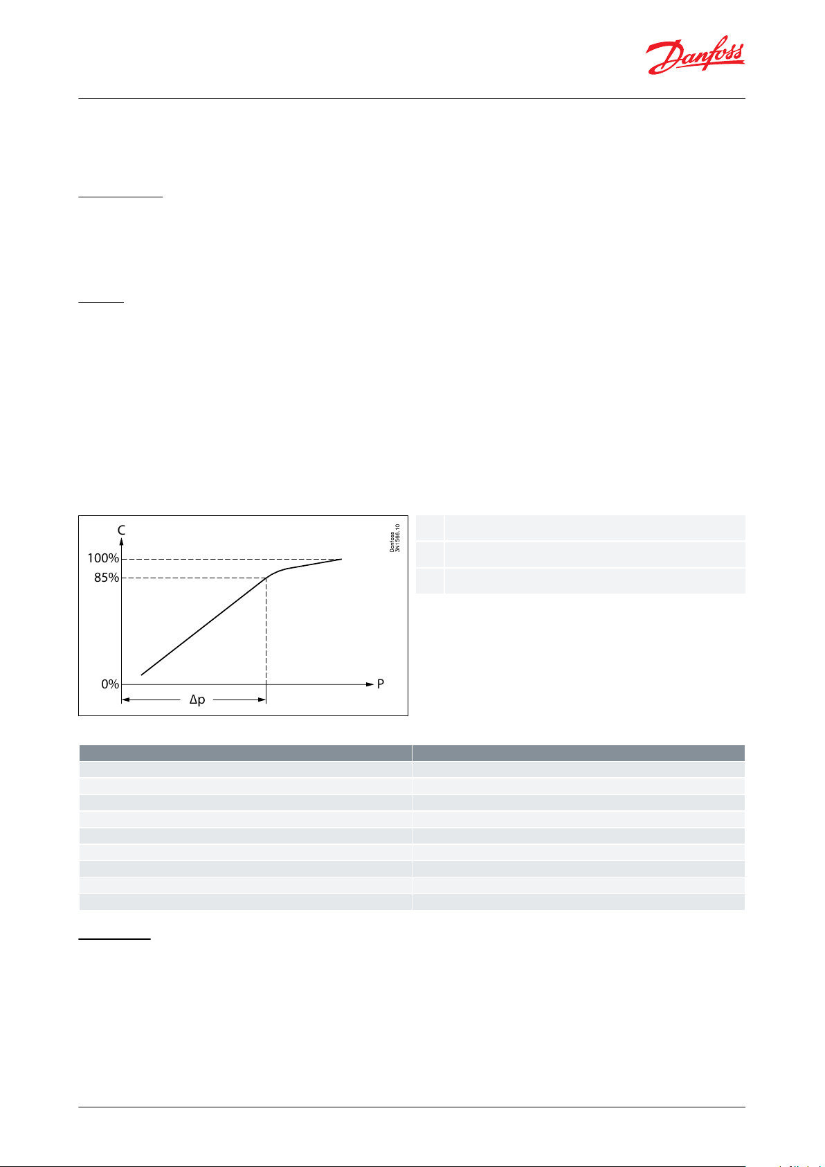
To obtain a precise control it can be recommended to only use 85% of the capacity. Below 85% the ratio between
ow and condensing dierence pressure is linear. Above 85% the ratio is no longer linear. To reach a 100% capacity
the water valve needs signicant increase of condensing pressure. See g. below.
Figure 7: Oset
Table 3: Oset
Valve size
The following data is used when selecting the size of the water valve
• Cooling capacity of condenser
• Temperature rise in cooling media
• Dierential pressure across valve
• Condensing temperature
• Specic heat capacity of cooling media
• Refrigerant
© Danfoss | Climate Solutions | 2021.02 AI250886497511en-001401 | 7
Page 8
Features
Calculation
Necessary mass ow
m. =
Q
c
Cp.(t2 − t1)
.3600 =
30
4.19 . (25 − 15)
. 3600 = 2577kg/h
Volume ow
V. =
m
.
ρ
=
2577
1000
= 2 . 6m3/h
[bar]
Danfoss
16D851
[m /h]
3
Pressure operated water valve, Type WVFX and WVS
Sizing Examples
Example 1:
• Condenser capacity Q0: 30 kW
• Condensing temperature tc: 35 °C
• Refrigerant: R404A
• Cooling media: water
• Specic heat capacity of water Cp: 4.19 kj / (kg*K)
• Water inlet temperature t1: 15 °C
• Water outlet temperature t2: 25 °C
• Pressure drop across valve ∆p: max. 1.0 bar
Table 4: Calculation for size
Figure 8: Selecting size
Selecting WVFX 20 code number
The saturated pressure for R404A: Tc = 35 °C → Pc = 15.5 barg
Choose a WVFX 20 with 4 – 23 barg range
Example 2:
• Condenser capacity Q0: 20 kW
• Condensing temperature tc: 35 °C
• Refrigerant: R134a
• Cooling media: Brine
• Density of brine ρ: 1015 kg / m
3
© Danfoss | Climate Solutions | 2021.02 AI250886497511en-001401 | 8
Page 9

Danfoss
3N15731
D
H2
H1
L1
L
L1
15
22
25
62
40
50
56
9
Ø4
Ø7.15
Danfoss
3N200.11
Danfoss
3-193.15
18 18
117148
71
128
Features
Calculation
Necessary mass ow
m. =
Q
c
Cp.(t2 − t1)
.3600 =
20
4.35 . (25 − 20)
. 3600 = 3310kg/h
Volume ow
V. =
m
.
ρ
=
3310
1015
= 3 . 26m3/h
kv value
Kv≥
V
.
1000 . Δp
ρ
=
V
.
1000 . 2.0
1015
= 2.32m3/h
Pressure operated water valve, Type WVFX and WVS
• Specic heat capacity of brine Cp : 4.35 kj (kg*K)
• Brine inlet temperature t1: 20 °C
• Brine outlet temperature t2: 25 °C
• Pressure drop across valve ∆p: max. 2.0 bar
Table 5: Calculation for size - SI units
Selecting size of WVFX 20
kv ≥ 2.32 m3 / h → WVFX 20
WVFX 20 has kv = 3.4 m3 / h and the necessary
capacity is below 85% of full capacity.
Code number
The saturated pressure for 134a: Tc = 35 °C Pc = 7.9 barg
Choose a WVFX 20 with 3.5 – 16 barg range
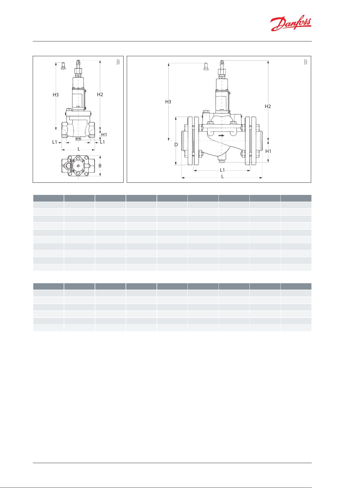
Dimensions [mm] and weights [kg]
Figure 9: WVFX 10 – 25
Figure 10: Bracket for WVFX 10 – 25
Figure 11: WVFX 32 – 40
© Danfoss | Climate Solutions | 2021.02 AI250886497511en-001401 | 9
Page 10
Danfoss
16D691
H3
H2
H1
L1 L1
B
L
Danfoss
16D031
L1
H1
H2
H3
D
L
TypeH1H2H3LL1B
ø
Net weight
WVFX 1091133–7211–551
WVFX 1591133–7214–551
WVFX 2091133–9016–552
WVFX 2596138–9519–552
WVS 3242243
234
1382085–4
WVS 4072271
262
19830100–7
WVS 5078277
268
315
218–16519WVS 6582293
284
320
224–18524WVS 8090325
316
370
265–20034WVS 100
100
345
336
430
315–220
44
TypeH1H2H3LL1B
ø
Net weight
WVS 3242259
250
1382085–4
WVS 4072287
278
19830100–7
WVS 5078293
2684
315
218–16519WVS 6582309
300
320
224–18524WVS 8090341
332
370
265–20034WVS 100
100
361
352
430
315–220
44
Pressure operated water valve, Type WVFX and WVS
Figure 12: WVS 32 – 40
Table 6: Pressure operated water valve
Figure 13: WVS 50 – 100
Table 7: Pressure operated water valve, type WVS - high pressure refrigerants
NOTE:
The diamentions for WVFX 32 - 40 is mentioned in Figure 11: WVFX 32 – 40. The net weight for WVFX 32 is 3.2 kg and
for WVFX 40 is 3.3 kg
© Danfoss | Climate Solutions | 2021.02 AI250886497511en-001401 | 10
Page 11

Type
Connection
(1)
Range
Code no.
Water side
Condenser side
[bar]
WVFX 10
G
3
⁄8
1
⁄4 in. / 6 mm are
3.5 – 16
003N1100
WVFX 10
G
3
⁄8
1
⁄4 in. / 6 mm are
4.0 – 23
003N1105
WVFX 15
G
1
⁄2
1
⁄4 in. / 6 mm are
3.5 – 16
003N2100
WVFX 15
G
1
⁄2
1
⁄4 in. / 6 mm are
4.0 – 23
003N2105
WVFX 15
G
1
⁄2
1
⁄4 in. / 6 mm are nut
4.0 – 23
003N2205
(2)
WVFX 20
G
3
⁄4
1
⁄4 in. / 6 mm are
3.5 – 16
003N3100
WVFX 20
G
3
⁄4
1
⁄4 in. / 6 mm are
4.0 – 23
003N3105
WVFX 20
G
3
⁄4
1
⁄4 in. / 6 mm are nut
4.0 – 23
003N3205
(2)
WVFX 25
G 1
1
⁄4 in. / 6 mm are
3.5 – 16
003N4100
WVFX 25
G 1
1
⁄4 in. / 6 mm are
4.0 – 23
003N4105
WVFX 32
G 1
1
⁄4
1
⁄4 in. / 6 mm are
4.0 – 17
003F1232
WVFX 40
G 1
1
⁄2
1
⁄4 in. / 6 mm are
4.0 – 17
003F1240
Type
Connection
(1)
Range
Code no.
Water side
Condenser side
[bar]
WVFX 15
G
1
⁄2
1
⁄4
in. / 6 mm
are
3.5 – 16
003N2101
WVFX 15
G
1
⁄2
1
⁄4
in. / 6 mm
are
4.0 – 23
003N2104
WVFX 20
G
3
⁄4
1
⁄4
in. / 6 mm
are
4.0 – 23
003N3104
WVFX 25
G 1
1
⁄4
in. / 6 mm
are
3.5 – 16
003N4101
WVFX 25
G 1
1
⁄4
in. / 6 mm
are
4.0 – 23
003N4104
Type
Connection
(1)
Range
Code no.
Water side
Condenser side
[bar]
WVFX 10
G
3
⁄8
1
⁄4
in. / 6 mm
are
15.0 – 29.0
003N1410
WVFX 15
G
1
⁄2
1
⁄4
in. / 6 mm
are
15.0 – 29.0
003N2410
WVFX 20
G
3
⁄4
1
⁄4
in. / 6 mm
are
15.0 – 29.0
003N3410
WVFX 25
G 1
1
⁄4
in. / 6 mm
are
15.0 – 29.0
003N4410
Type
Connection
(1)
Code no.
Valve body
Pilot unit
(3)
Pilot unit for R410A
and R744
(3)
Flange set
(4)
Servo spring for dif‐
ferential pressure
range of 1 – 10 bar
WVS 32
G 1 1⁄2
(1)
016D5032
016D1017
016D1018
–
016D1327
WVS 40
G 1 1⁄2
(1)
016D5040
016D1017
016D1018
–
016D0575
WVS 50
2 in. weld
ange
016D5050
(2)
016D1017
016D1018
027N3050
016D0576
Pressure operated water valve, Type WVFX and WVS
Ordering
Ordering WVFX, commercial type
Table 8: Ordering WVFX, commercial type
(1)
(1)
ISO 228-1
ISO 228-1
(2)
(2)
WVFX 15 with 1 m capillary tube and are nut with valve depressor
WVFX 15 with 1 m capillary tube and are nut with valve depressor
Ordering WVFX, maritime type (stainless steel version)
Table 9: Ordering WVFX, maritime type (stainless steel version)
(1)
(1)
ISO 228-1
ISO 228-1
Ordering WVFX, commercial type (high pressure refrigerants, MWP 45.2 bar)
Table 10: Ordering WVFX, commercial type (high pressure refrigerants, MWP 45.2 bar)
(1)
(1)
ISO 228-1
ISO 228-1
Ordering WVS, commercial type
Table 11: Ordering WVS, commercial type
© Danfoss | Climate Solutions | 2021.02 AI250886497511en-001401 | 11
Page 12

Type
Connection
(1)
Code no.
Valve body
Pilot unit
(3)
Pilot unit for R410A
and R744
(3)
Flange set
(4)
Servo spring for dif‐
ferential pressure
range of 1 – 10 bar
WVS 65
2 1⁄2 in. weld ange
016D5065
(2)
016D1017
016D1018
027N3065
016D0577
WVS 80
3 in. weld ange
016D5080
(2)
016D1017
016D1018
027N3080
016D0578
WVS 100
4 in. weld ange
016D5100
(2)
016D1017
016D1018
027N3100
016D0579
Description
Code no.
1 m capillary tube
1
⁄4 in. (6 mm) are coupling nuts at each end
060-017166
Bracket for WVFX 10 – 25
003N0388
Pressure operated water valve, Type WVFX and WVS
(1)
(1)
ISO 228-1
ISO 228-1
(2)
(2)
Parts included: valve body, ange gaskets, ange bolts and screws for pilot valve.
Parts included: valve body, ange gaskets, ange bolts and screws for pilot valve.
(3)
(3)
Parts included: control element and spring housing.
Parts included: control element and spring housing.
(4)
(4)
Parts included: 2 anges
Parts included: 2 anges
Accessories
Table 12: Accessories
© Danfoss | Climate Solutions | 2021.02 AI250886497511en-001401 | 12
Page 13

Document name
Document type
Document topic
Approval authority
003N9613.AB
Manufacturers Declaration
PED
Danfoss
003N9614.AA
Manufacturers Declaration
China RoHS
Danfoss
003N9616.AA
Manufacturers Declaration
ATEX
Danfoss
003N9617.AB
Manufacturers Declaration
PED/RoHS
Danfoss
UL SA7200
Mechanical - Safety Certicate
UL
Pressure operated water valve, Type WVFX and WVS
Certicates, declarations, and approvals
The list contains all certicates, declarations, and approvals for this product type. Individual code number may have
some or all of these approvals, and certain local approvals may not appear on the list.
Some approvals may change over time. You can check the most current status at danfoss.com or contact your local
Danfoss representative if you have any questions.
Table 13: Valid Certicates, declarations, and approvals
© Danfoss | Climate Solutions | 2021.02 AI250886497511en-001401 | 13
Page 14

Online support
Danfoss oers a wide range of support along with our products, including digital product information, software,
mobile apps, and expert guidance. See the possibilities below.
The Danfoss Product Store
The Danfoss Product Store is your one-stop shop for everything product related—no matter where
you are in the world or what area of the cooling industry you work in. Get quick access to essential
information like product specs, code numbers, technical documentation, certications, accessories,
and more.
Start browsing at store.danfoss.com.
Find technical documentation
Find the technical documentation you need to get your project up and running. Get direct access to
our ocial collection of data sheets, certicates and declarations, manuals and guides, 3D models
and drawings, case stories, brochures, and much more.
Start searching now at www.danfoss.com/en/service-and-support/documentation.
Danfoss Learning
Danfoss Learning is a free online learning platform. It features courses and materials specically
designed to help engineers, installers, service technicians, and wholesalers better understand the
products, applications, industry topics, and trends that will help you do your job better.
Create your Danfoss Learning account for free at www.danfoss.com/en/service-and-support/learning.
Get local information and support
Local Danfoss websites are the main sources for help and information about our company and
products. Find product availability, get the latest regional news, or connect with a nearby expert—all
in your own language.
Find your local Danfoss website here: www.danfoss.com/en/choose-region.
Coolselector®2 - nd the best components for you HVAC/R system
Coolselector®2 makes it easy for engineers, consultants, and designers to nd and order the best
components for refrigeration and air conditioning systems. Run calculations based on your operating
conditions and then choose the best setup for your system design.
Download Coolselector®2 for free at coolselector.danfoss.com.
Danfoss can accept no responsibility for possible errors in catalogues, brochures and other printed material. Danfoss reserves the right to alter its
products without notice. This also applies to products already on order provided that such alterations can be made without subsequential
changes being necessary in specications already agreed. All trademarks in this material are property of the respective companies. Danfoss and
the Danfoss logotype are trademarks of Danfoss A/S. All rights reserved.
© Danfoss | Climate Solutions | 2021.02 AI250886497511en-001401 | 14
 Loading...