

Page 1
User Manual
PLUS+1® GUIDE Software
WS403x/WS503x Function Block Library
powersolutions.danfoss.com
Page 2

User Manual
WS403x/WS503x Function Block Library
Revision history Table of revisions
Date Changed Rev
May 2016 First edition 0101
2 | © Danfoss | May 2016 AQ00000215en-US0101
Page 3

User Manual
WS403x/WS503x Function Block Library
Contents
About this manual
Organization and Headings..........................................................................................................................................................5
Special Text Formatting................................................................................................................................................................. 5
WS FW, WS Configurator and Default Configuration..........................................................................................................5
Introduction
Blocks Structure................................................................................................................................................................................ 6
WS403x/WS503x Object................................................................................................................................................................ 8
Object Access.....................................................................................................................................................................................8
Custom objects...............................................................................................................................................................................12
Device variables
Parameter name: DevApp_MasterMode...............................................................................................................................14
Parameter name: DevCfg_VerStr............................................................................................................................................. 14
Parameter name: OperationTmTot......................................................................................................................................... 15
Parameter name: CAN1_NodeID..............................................................................................................................................15
Parameter name: CAN1_Baud_Rate....................................................................................................................................... 15
Parameter name: Dis_En_Objs..................................................................................................................................................16
Parameter name: RemoteSafetyFncAct.................................................................................................................................16
Accelerometer
Parameter name: Lateral............................................................................................................................................................. 18
Parameter name: Longitudinal................................................................................................................................................. 18
Parameter name: Vertical............................................................................................................................................................19
Remote Safety Mechanism
Parameter name: State.................................................................................................................................................................20
Parameter name: State_CAN..................................................................................................................................................... 21
Parameter name: State_Internal...............................................................................................................................................21
Parameter name: State_Combo............................................................................................................................................... 21
Local Geofence
Parameter name: Mode............................................................................................................................................................... 22
Parameter name: Coord1_Long............................................................................................................................................... 22
Parameter name: Coord1_Lat................................................................................................................................................... 23
Parameter name: Coord2_LongRad........................................................................................................................................23
Parameter name: Coord2_Lat................................................................................................................................................... 24
Parameter name: Status_Chg_UTC ........................................................................................................................................24
Parameter name: Status...............................................................................................................................................................25
Logging
Parameter name: SendFileCmd................................................................................................................................................ 26
Parameter name: En_SD_CardLog.......................................................................................................................................... 26
Parameter name: FileHeaderText.............................................................................................................................................26
Parameter name: FileUploadPeriod........................................................................................................................................ 27
Mobile
Parameter name: AntennaStatus ............................................................................................................................................28
Parameter name: Network_State.............................................................................................................................................28
Parameter name: Modem_Result.............................................................................................................................................29
Parameter name: Signal_Quality..............................................................................................................................................29
Parameter name: Net_Mode_Select....................................................................................................................................... 29
Parameter name: Net_Mode_Cur............................................................................................................................................ 30
Parameter name: ActNetProvider............................................................................................................................................30
Parameter name: SIM_IMSI.........................................................................................................................................................31
Parameter name: SIM_ICCID......................................................................................................................................................31
Parameter name: SIM_PIN_ErrFlg............................................................................................................................................31
Parameter name: StateMachErrCode..................................................................................................................................... 32
Parameter name: CMS_ErrNum................................................................................................................................................32
Parameter name: CME_ErrNum................................................................................................................................................32
Parameter name: Serv_ReconnectTm....................................................................................................................................33
Parameter name: Eng_IMEI_Num............................................................................................................................................33
©
Danfoss | May 2016 AQ00000215en-US0101 | 3
Page 4

User Manual
WS403x/WS503x Function Block Library
Contents
Parameter name: Eng_Identity................................................................................................................................................. 33
Parameter name: Eng_Version..................................................................................................................................................34
Positioning
Parameter name: Longitude .....................................................................................................................................................35
Parameter name: Latitude.......................................................................................................................................................... 35
Parameter name: SpeedOvrGnd...............................................................................................................................................36
Parameter name: Heading..........................................................................................................................................................36
Parameter name: GPS _Odometer...........................................................................................................................................36
Parameter name: DataValid........................................................................................................................................................37
Parameter name: AntennaStatus ............................................................................................................................................37
Parameter name: ActiveSatellites............................................................................................................................................ 38
Parameter name: Mode_GNSS..................................................................................................................................................38
Parameter name: EngineVersion..............................................................................................................................................38
Security Variables
Parameter name: RemoteAccessPass.....................................................................................................................................39
Parameter name: SIM_PIN.......................................................................................................................................................... 39
Parameter name: UMTS_RoamHandle...................................................................................................................................39
Parameter name: UMTS _DNS1_..............................................................................................................................................40
Parameter name: UMTS _DNS2_..............................................................................................................................................40
Parameter name: ISP_Username..............................................................................................................................................40
Parameter name: ISP_Password............................................................................................................................................... 41
Parameter name: UMTS_APN....................................................................................................................................................41
Parameter name: RemServAddr............................................................................................................................................... 41
Parameter name: RemServPort.................................................................................................................................................41
Parameter name: SMS_ServCenterAddr................................................................................................................................42
Predefined SMS
Parameter name: Predef_XMIT_Busy..................................................................................................................................... 43
Parameter name: Predef_XMIT_Txt.........................................................................................................................................43
Parameter name: Predef_XMIT_Dest......................................................................................................................................44
Parameter name: XMIT_Dest..................................................................................................................................................... 44
Parameter name: XMIT_Txt........................................................................................................................................................45
Parameter name: XMIT_Request..............................................................................................................................................46
Parameter name: XMIT_Txt_Coding.......................................................................................................................................46
Parameter name: Rcv_Indication............................................................................................................................................. 47
Parameter name: Rcv_Originator.............................................................................................................................................47
Parameter name: Rcv_Timestamp...........................................................................................................................................47
Parameter name: Rcv_Txt........................................................................................................................................................... 48
Parameter name: Rcv_Txt_Coding.......................................................................................................................................... 48
Power Management
Parameter name: Time_To_Sleep............................................................................................................................................49
Parameter name: Enbl_Wake-Up_Flags................................................................................................................................ 49
Parameter name: Shut_down_DelayTm............................................................................................................................... 49
Parameter name: CyclicWakeupTm........................................................................................................................................ 50
Device I/O
Parameter name: Clamp15.........................................................................................................................................................51
4 | © Danfoss | May 2016 AQ00000215en-US0101
Page 5
W
User Manual
WS403x/WS503x Function Block Library
About this manual
Organization and Headings
To help you quickly find information in this manual, the material is divided into sections, topics,
subtopics, and details, with descriptive headings set in bold type. Chapter or section titles appear at the
top of every page in large bold type.
Special Text Formatting
Controls and indicators are set in bold black type.
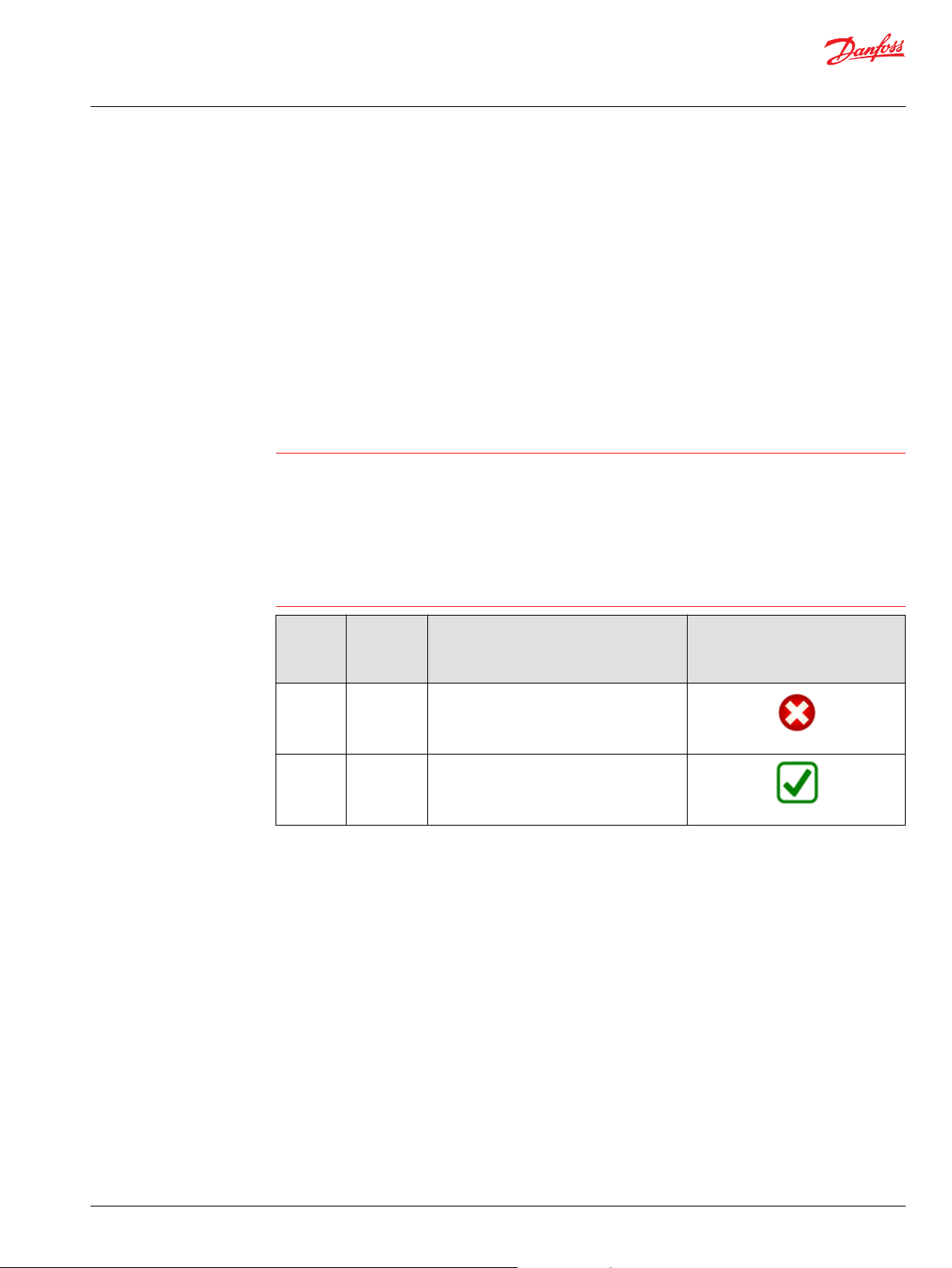
WS FW, WS Configurator and Default Configuration
Warning
The WS function block is complaint with the WS403x/WS503x FW version > 12.00 with the unit
Configured with the DanfossDefault 2.0 configuration.
Most of the objects are available also on previous FW version, but in that case it is recommended to check
the object index and sub-index.
In case of WS503x the DanfossDefault 2.0 configuration is designed to manage the information available
on CAN1 and not on CAN2.
In case of WS customized configurations it’s required to check the alignment of the objects information
before to use the blocks. In case of more clarifications, please contact Danfoss support.
WS403x/
WS503x
FW
Version
10.04 to
12.00
> 12.00 > 2.02.08
WS
Configurato
r Version
2.02.05 to
2.02.08
WS Default Configuration WS compliance
WS403_DanfossDefault
WS403-J_DanfossDefault
WS503_DanfossDefault
WS503-BP_DanfossDefault
WS403_DanfossDefault 2.0
WS403-J_DanfossDefault 2.0
WS503_DanfossDefault 2.0
WS503-BP_DanfossDefault 2.0
©
Danfoss | May 2016 AQ00000215en-US0101 | 5
Page 6
User Manual
WS403x/WS503x Function Block Library
Introduction
The WS Function Block is intended to be used with Danfoss Power Solutions WS403x and WS503x
devices.
The communication type is based on the CAN 2.0 A/B network.
Only one parameter from the WS device can be read or written at a time.
Blocks Structure
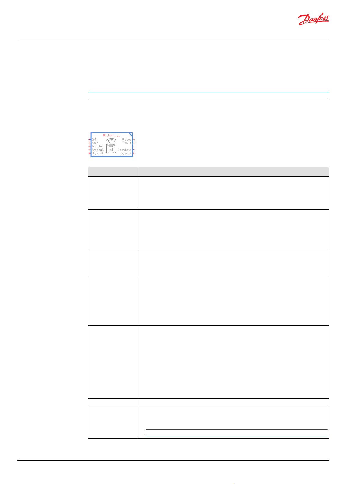
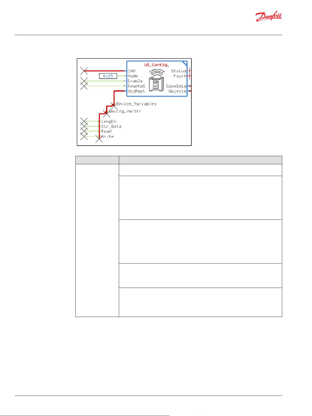
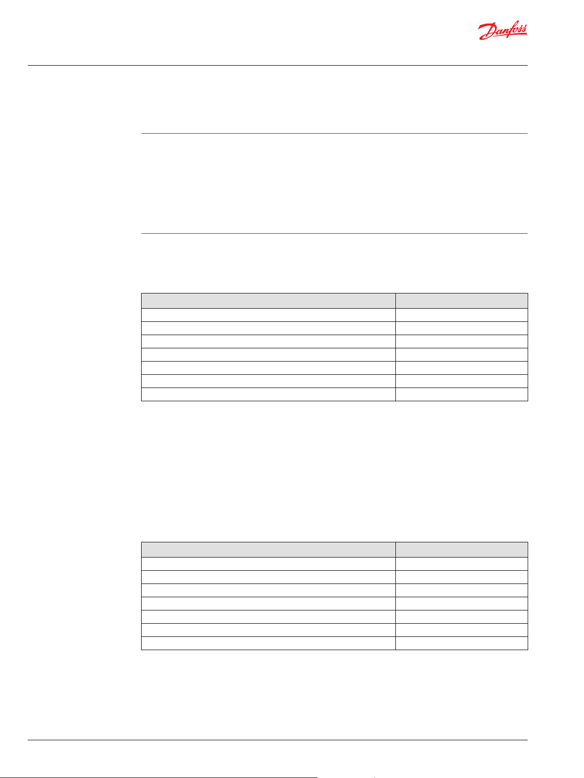
At the top level the compliance block named WS_Config has the following structure and interface:
Item Description
CAN Bus used to determine which physical CAN bus available on the ECU and which physical
Node WS403x/WS503x CAN Bus address (WS403x/WS503x Device CANopen Node ID parameter
Enable CANopen SDO communication:
ResetWS A positive transition will send a reset command to WS403x/WS503x
ObjRqst & Objects Bus that contains selected WS403x/WS503x Object Sets buses:
Block Version It indicates the released version of the block
Status Status output, a bitwise code where multiple items can be reported at a time:
CAN port of the hardware is used to receive the data from (this variable can be found in the
CAN sub-bus if using the Main Template).
Value range: NA
•
Unit: NA
•
value)
Parameter Type: U8
•
Value range: between 1 and 127
•
Default value: 0x25 (37 decimal)
•
Unit: NA
•
Value Range:
False (Disable CANopen SDO communication, NMT is still available to reset the WS
•
True (Enable CANopen SDO communication)
•
Parameter Type: Boolean
Default value: 0
Unit: NA
Value range:
False (No effect)
•
True (Reset WS403x/WS503x)
•
Accelerometer_
•
Device_Vars_
•
Local_Geofence_
•
Logging_
•
Mobile_Vars_
•
Positioning_
•
Remote_Safety_
•
Security_Vars_
•
SMS_
•
Custom_
•
0x0000: Status OK
•
0x8008: A parameter value is out of range
•
Block will not store data in this case. Send and Receive capabilities are also disabled.
6 | © Danfoss | May 2016 AQ00000215en-US0101
Page 7
User Manual
WS403x/WS503x Function Block Library
Introduction
(continued)
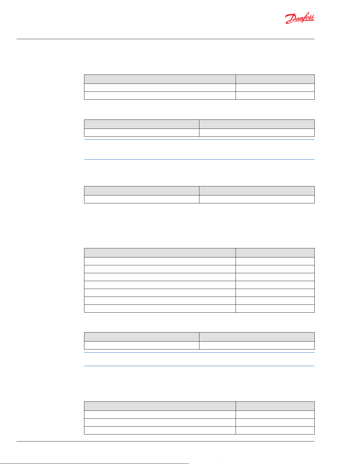
Item Description
Fault Fault output, a bitwise code where multiple items can be reported at a time:
CommData Bus that includes the signals used to define the status of the communication with WS403x/
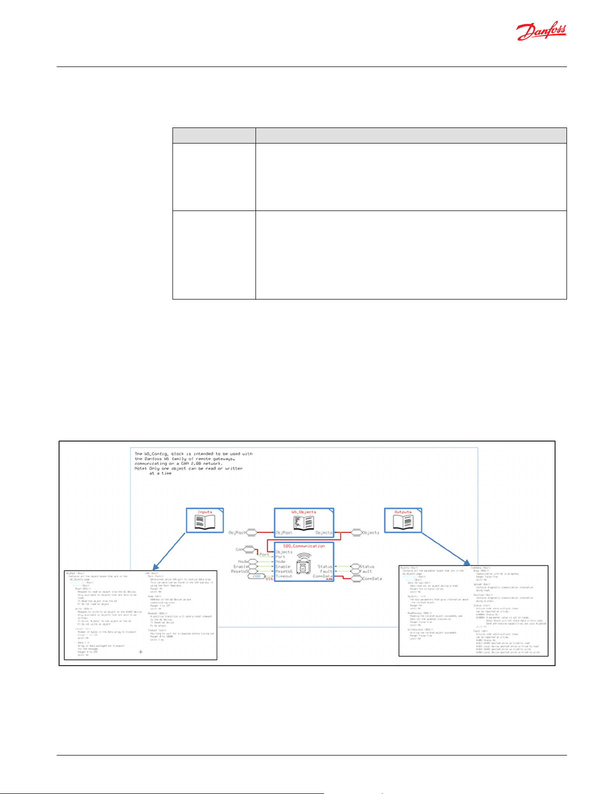
Going in one level to the WS_Config page, more details are available in order to facilitate the developers
in the usage of the WS Library.
Four pages are shown:
•
WS_Objects includes the details of all available objects for communication
•
SDO_Communication: Service Data Objects (SDOs) are used for direct access to WS403x/WS503x
devices. With these service data objects, WS403x/WS503x objects can be read and written, where
communication always takes place as a logical 1:1 connection between two nodes (e.g. a configuring
node and a node to be configured). This page is blocked and can’t to be modified.
•
Inputs: includes more details about the inputs of WS_Config page
•
Outputs: includes more details about the outputs of WS_Config page
0x00: Status OK
•
0x01: Aborted while we tried to read
•
0x02: Local device aborted while we tried to read
•
0x04: Aborted while we tried to write
•
0x08: Local device aborted while we tried to write
•
WS503x:
Upload: Bus that contains diagnostic communication information being read.
Download: Bus that contains diagnostic communication information being written.
Busy: communication with WS403x/WS503x in progress.
Parameter Type: Boolean
•
Value range: False / True
•
Unit: NA
•
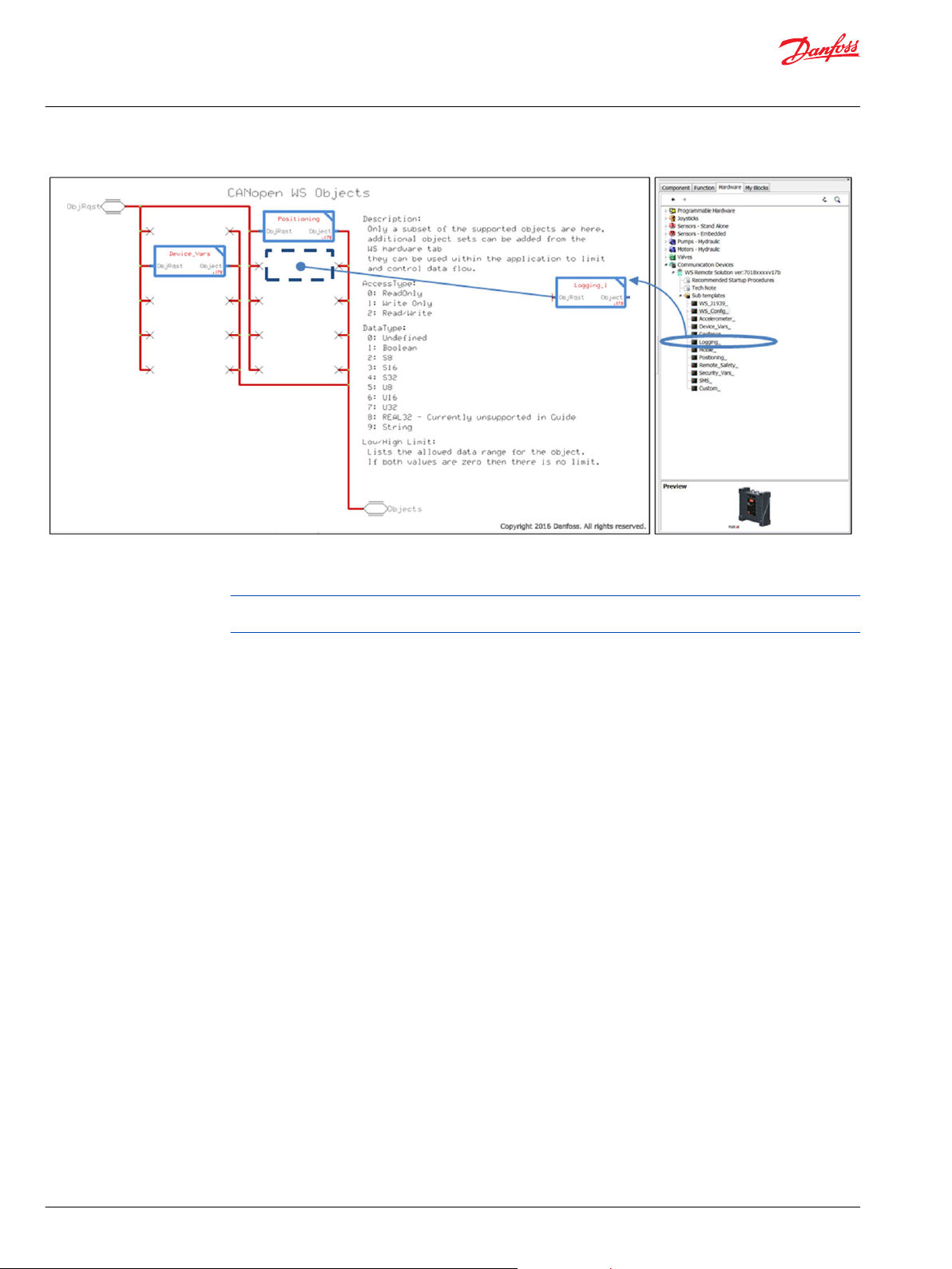
Going into the WS Objects page the user can include different Objects Sets specific for the WS403x or
WS503x based on the unit used.
Each Objects Set has an input bus (ObjRqst) and an output bus (Object). By default only a subset of the
supported object are already included (Device_Vars_ and Positioning_).
©
Danfoss | May 2016 AQ00000215en-US0101 | 7
Page 8
User Manual
WS403x/WS503x Function Block Library
Introduction
WS403x/WS503x Object
Object Access
The Objects Sets can be added to the WS Objects page from the WS hardware tab and are based on
different WS functionalities.
The input and output buses of the added Object Sets must be connected to the same bus included on
the WS Objects page.
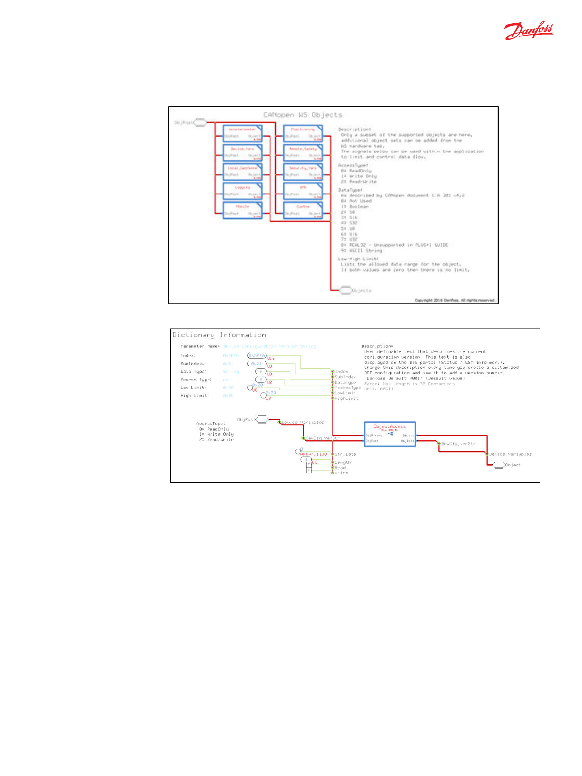
Each object is described by the following details:
•
Parameter name: a symbolic name of the object
•
Index: the 16-bit address to access information in the object
•
Subindex: for specific objects the address is extended by a supplemental 8-bit address
•
Data Type: gives the data type of the variable (or the data type of all variables of an array)
•
Access Type: which gives information on the access rights for this entry (attribute), can be:
0. Read-Only
1. Write-Only
2. Read/Write
•
Low Limit: the limit on the lower side of the object value
•
High Limit: the limit on the higher side of the object value
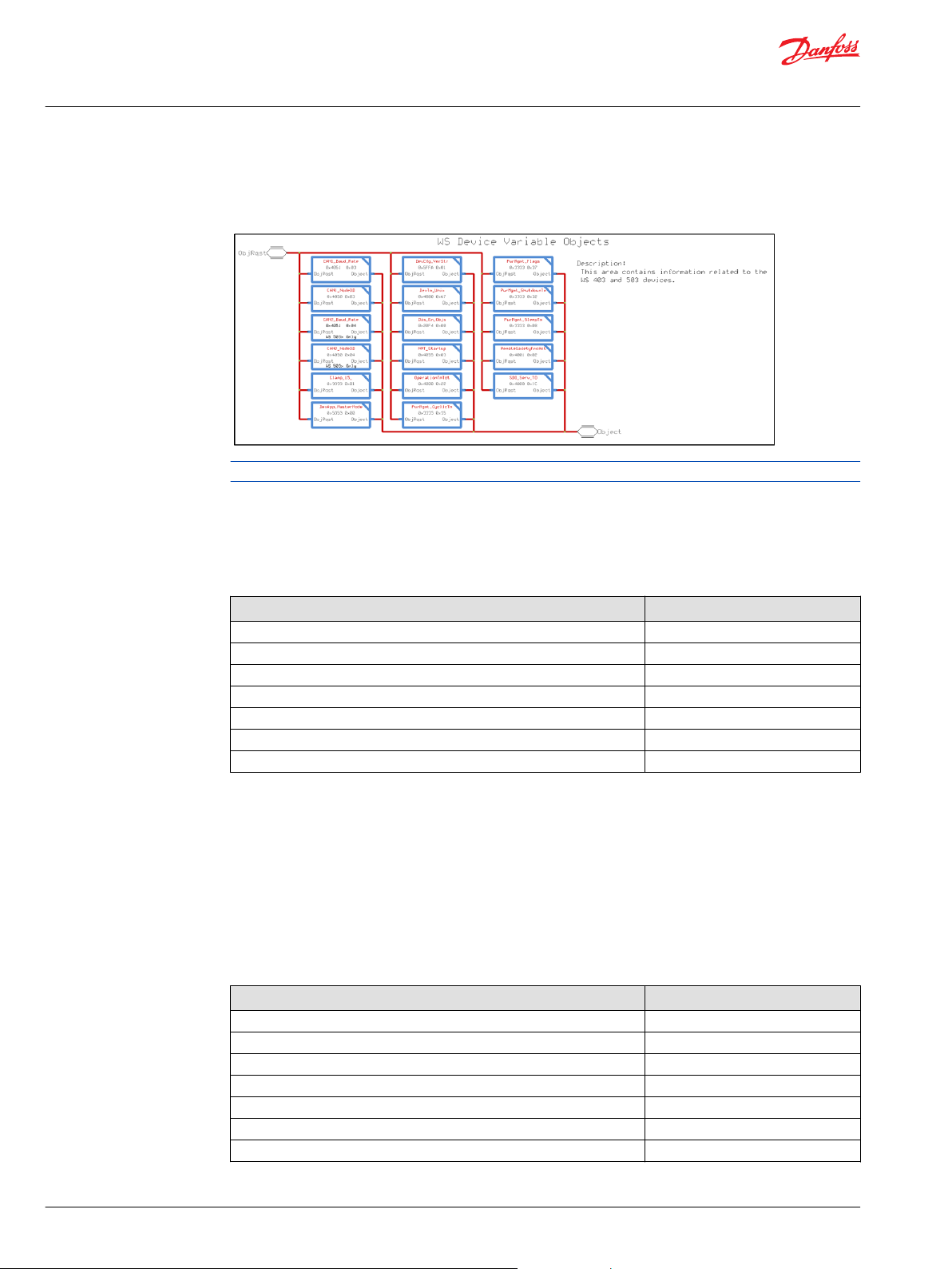
Going one level inside an Object Set (i.e. Device_Vars) are shown the related objects:
8 | © Danfoss | May 2016 AQ00000215en-US0101
Page 9
User Manual
WS403x/WS503x Function Block Library
Introduction
The object we’re looking for is DevCfg_VerStr and the related page includes the object details.
It’s important to note:
•
Object description
•
Data Type: String
•
Access Type: R/W
On the outer level you can access the object by following the bus structure, the bus includes the
following available signals:
©
Danfoss | May 2016 AQ00000215en-US0101 | 9
Page 10
User Manual
WS403x/WS503x Function Block Library
Introduction
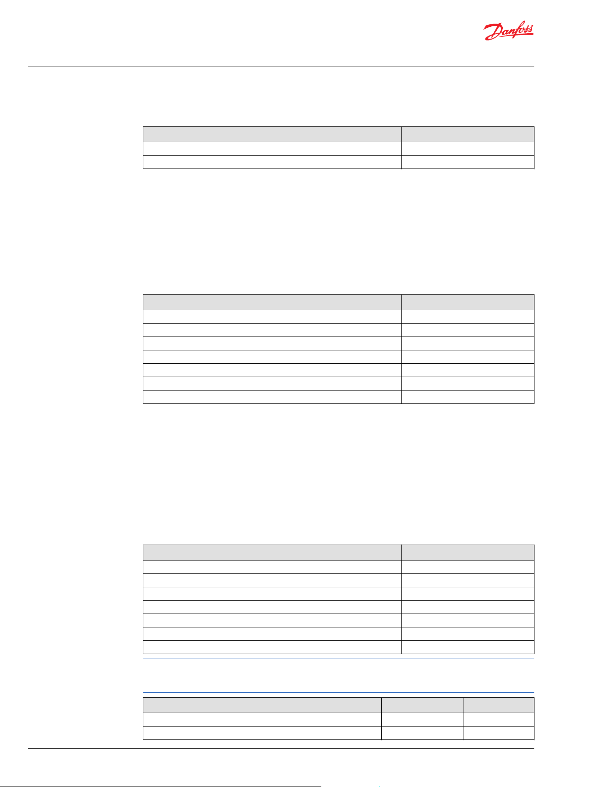
Item Description
ObjRqst Bus that include all the parameter buses that contains the most important WS403x/WS503x
Objects Sets bus. Each Object Sets buses includes the following control signals:
Read: request a read an object from WS403x/WS503x
Only available for the objects that have the R (Read) permission.
Parameter Type: Boolean
•
Value range
•
False (Do not read the object)
‒
True (Read the object from the WS403x/WS503x)
‒
Unit: NA
•
Write: request to write to an object on the WS403x/WS503x
Only available for the objects that have the W (Write) permission.
Parameter Type: Boolean
•
Value range
•
False: Do not write an object
‒
True: Write “*_Data” to the object on WS403x/WS503x
‒
Unit: NA
•
Length: Determines the length of the data to be sent, minimum size is one.
Parameter Type: U8
•
Value range: 1 to 100
•
Unit: NA
•
Str_Data: Is always an array that contains the data to be written. If the object is Read only
set to an array of size one with any data
Parameter Type: *_Data(*)
•
Value range: 0 to 255
•
Unit: NA
•
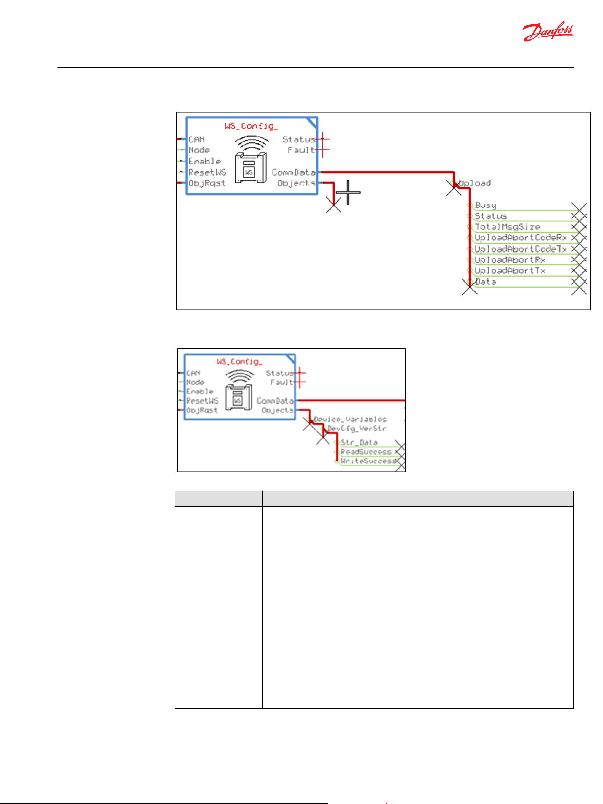
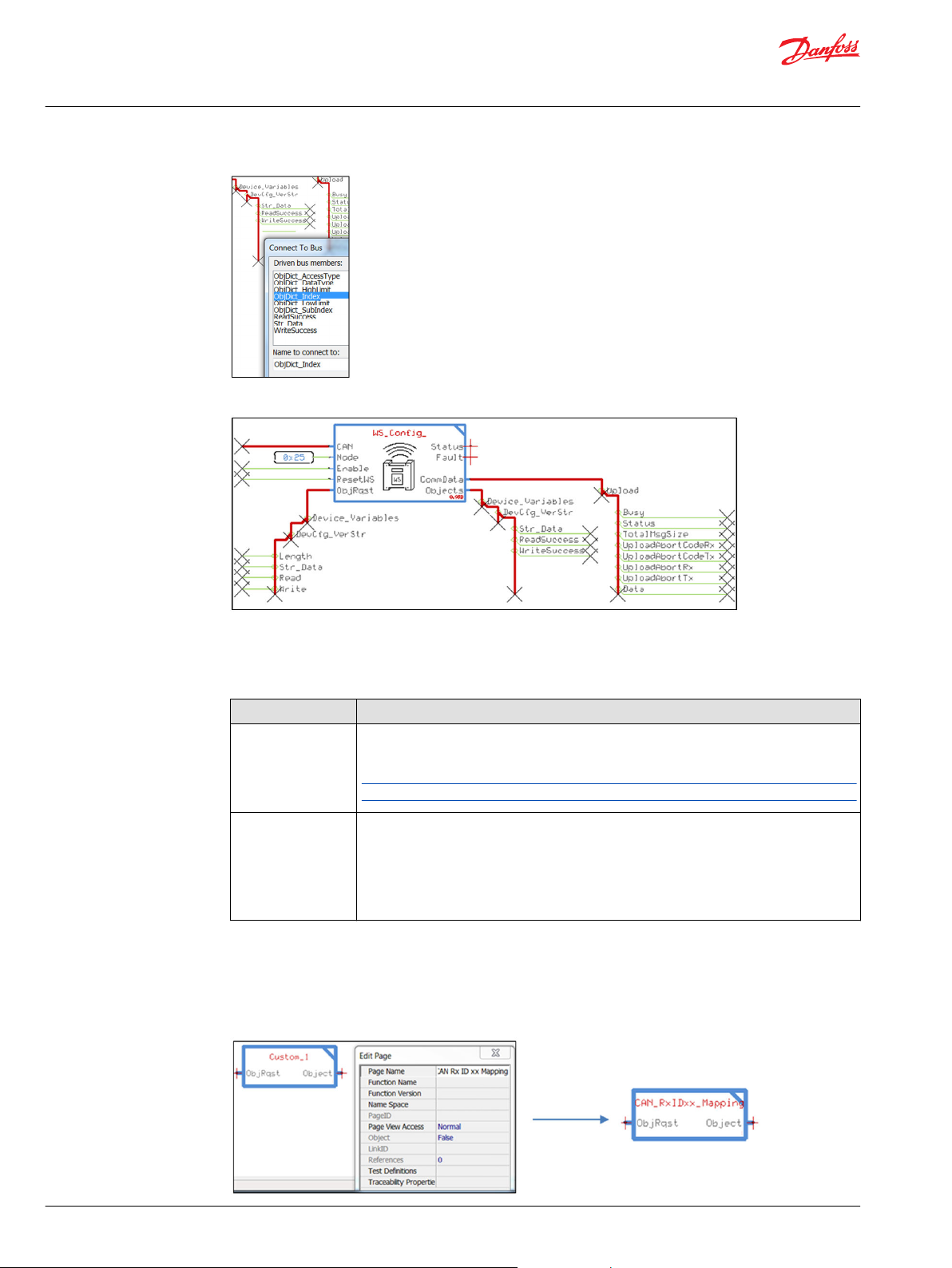
On the WS_Config page the output CommData Bus contains communication data for the current
message. The Upload bus is shown below. The Download bus has a similar set of signals.
10 | © Danfoss | May 2016 AQ00000215en-US0101
Page 11
User Manual
WS403x/WS503x Function Block Library
Introduction
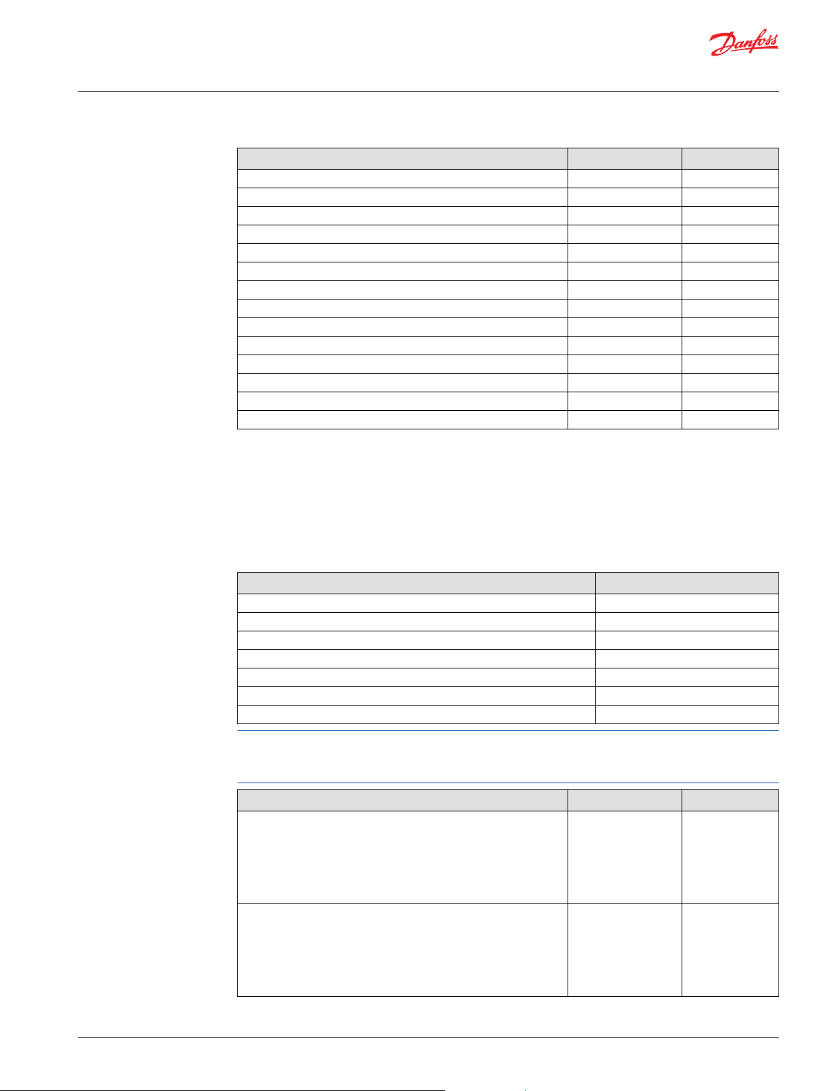
The data that is read from an object is placed into the Objects bus and will follow a similar bus
architecture to access the signals.
Item Description
Objects Bus that include all the Object Sets buses that contains the most important WS403x/
The information about the Objects are also available on the bus and can be used for processing:
©
Danfoss | May 2016 AQ00000215en-US0101 | 11
WS503x objects. Each Object Set buses includes the following control signals:
Str_Data: Contains the data read from the object, the data type varies. See
•
ObjDict_DataType on this bus for real-time information to process the data.
Parameter Type: Array[x]U8
‒
Value range: number of bytes varies
‒
Unit: NA
‒
ObjDict_X (x): various parameters that give information about the related object
•
Value range: NA
‒
Unit: NA
‒
ReadSuccess: Pulses true when an object was successfully read, see Data for the
•
updated information.
Parameter Type: Boolean
‒
Value range: False / True
‒
Unit: NA
‒
WriteSuccess: Pulses true when an object was successfully written.
•
Parameter Type: Boolean
‒
Value range: False / True
‒
Unit: NA
‒
Page 12
User Manual
WS403x/WS503x Function Block Library
Introduction
The full interface to a single R/W object:
Custom objects
When reading or writing an object it is recommended to monitor the Read/WriteSuccess to verify that the
message was properly received. By monitoring the Fault signal one can see if communications were
aborted.
Item Description
Status Status output, a bitwise code where multiple items can be reported at a time:
0x0000: Status OK
•
0x8008: A parameter value is out of range
•
Note: Block will not store data in this case. Send and Receive capabilities are also disabled
Fault Fault output, a bitwise code where multiple items can be reported at a time:
0x00: Status OK
•
0x01: WS403 aborted while we tried to read
•
0x02: Local device aborted while we tried to read
•
0x04: WS403 Aborted while we tried to write
•
0x08: Local device aborted while we tried to write
•
Custom_ Object Set can be used to include additional objects that not are included to the WS403x/
WS503x Danfoss Default Configuration 2.0 (i.e. some internal variables used to map customized
information received from CAN bus). In that case it is recommended to rename the page with the name
of the Group of Objects (press Q than, click on the page and edit the page name),
12 | © Danfoss | May 2016 AQ00000215en-US0101
Page 13
User Manual
WS403x/WS503x Function Block Library
Introduction
Then enter the page:
Write the description of the Object Set and based on the different Objects type use the predefined pages
for each object.
Change the name of the page with the name of the object, then enter to the object page and set the
object characteristics (index, sub-index, the bus names will need to be updated, etc…).
Do not introduce WS objects that are not available on the WS unit selected (i.e. Objects specific for
WS503 are not included on WS403 or customized objects not defined on WS unit), for more details see
Appendix A.
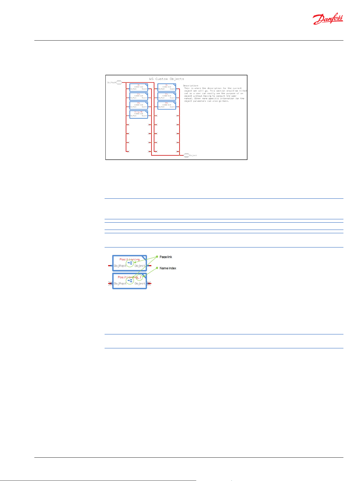
Objects that are unneeded can be deleted.
If a duplicated Object Set is placed on the project the ‘linked page’ symbol will be shown on the page and
to the end of page name will be added automatically and index number (PageName_# #: index number).
Change the bus names 'Custom' and 'Obj_Name_Str' according with the custom object created (object
group and object name).
Connect the signals Str_Data, Length, Read and Write to the application in order to manage the object.
Assign CP to all the relevant object characteristics (xx_Data, ObjDict_Index, ObjDict_SubIndex, etc...).
We recommend that the application developer include the expected object signals control (for example
the signal range limitation check, etc..).
©
Danfoss | May 2016 AQ00000215en-US0101 | 13
Page 14
User Manual
WS403x/WS503x Function Block Library
Device variables
WS403x and WS503x has some variables that can be used to manage the behavior of the device . Each
device variable have a specific page and indicate the index and sub-index address. Each page has an
input bus (ObjRqst) and an output bus (Object)
The device parameters require the WS to reset before they take effect.
Parameter name: DevApp_MasterMode
Define the WS403x or WS503x connection mode to DTS portal. The device mode will be active after a
reset of the unit. If bit 7 is set when writing the value, then the reset will be performed immediately.
DevApp_MasterMode Values
Index 0x5353
Subindex 0x00
Data Type U8
Access Type R/W
Low Limit 0
High Limit 255
Default Value 2
Values description:
•
•
Parameter name: DevCfg_VerStr
User defined text to describe the current configuration version.
Change this description every time you create a customized DOD configuration and use to add a version
number.
DevCfg_VerStr Values
Index 0x5FFA
Subindex 0x01
Data Type array of character (string)
Access Type R/W
Low Limit 0
High Limit 32 characters
Default Value ‘WSxxx Danfoss Default 2.0’
0: Data Logging/File Transfer mode
2: Real Time Connection mode (Default value)
14 | © Danfoss | May 2016 AQ00000215en-US0101
Page 15
User Manual
WS403x/WS503x Function Block Library
Device variables
Parameter name: OperationTmTot
Total WS403x/WS503x operation time expressed in [sec].
OperationTmTot Values
Index 0x4000
Subindex 0x22
Data Type U32
Access Type RO
Low Limit 0
High Limit 4294967295
Default Value 0
the value 0x80000000 indicates an invalid value so repeat the upload of the value again.
Parameter name: CAN1_NodeID
WS403x/WS503x Node ID for CAN1 interface
CAN1_NodeID Values
Index 0x4050
Subindex 0x03
Data Type U8
Access Type R/W
Low Limit 1
High Limit 127
Default Value 37 (0x25)
Parameter name: CAN1_Baud_Rate
Available Baud Rates on CAN1 Interface.
CAN1_Baud_Rate Values
Index 0x4051
Subindex 0x03
Data Type U8
Access Type R/W
Low Limit 0
High Limit 10
Default Value 3
Values description:
•
0: 1.000.000 baud
•
1: 800.000 baud
•
2: 500.000 baud
•
3: 250.000 baud (Default Value)
•
4: 125.000 baud
•
5: 100.000 baud
•
6: 50.000 baud
•
7: 20.000 baud
•
8: 10.000 baud
©
Danfoss | May 2016 AQ00000215en-US0101 | 15
Page 16
User Manual
WS403x/WS503x Function Block Library
Device variables
•
9: 83.333 baud
•
10: Customer specific Baud Rate: use Device Variable SFR-CAN-Baud Rate
The PLUS+1 supported baudrates are:
1.000.000 baud
•
500.000 baud
•
250.000 baud (Default Value)
•
125.000 baud
•
100.000 baud
•
50.000 baud
•
Parameter name: Dis_En_Objs
Switch ON/OFF CANopen Objects access (from the CAN side).
Dis_En_Objs Values
Index 0x20F4
Subindex 0x00
Data Type U8
Access Type R/W
Low Limit 0
High Limit FF
Default Value 0
Values description:
•
0x00: CANopen Stack completely active (Default Value)
•
0x01: The following CANopen Objects are disabled
SDO-Server-Object
‒
SDO-Client-Object
‒
NMT-Object
‒
Parameter name: RemoteSafetyFncAct
Switch ON/OFF the remote safety function activated by the configured CAN message.
RemoteSafetyFncAct Values
Index 0x4001
Subindex 0x02
Data Type U8
Access Type R/W
Low Limit 0
High Limit 1
Default Value 1
Values definition:
•
0: Full free access of read and write to the remote application
•
1: Limited access to the remote application active, read of data is not limited (default value)
To disable the remote safety mechanism:
1. set the variable to 0
16 | © Danfoss | May 2016 AQ00000215en-US0101
Page 17

User Manual
WS403x/WS503x Function Block Library
Device variables
2. download the variable to WS
3. power cycle or reset WS
©
Danfoss | May 2016 AQ00000215en-US0101 | 17
Page 18

User Manual
WS403x/WS503x Function Block Library
Accelerometer
WS403x/WS503x has an accelerometer that can detect acceleration on three axes, allowing it to sense
motion and orientation.
Each axial acceleration has a specific page and indicates the index and sub-index address. Each page has
an input bus (ObjRqst) and an output bus (Object)
Parameter name: Lateral
Lateral Values
Index 0x5E02
Subindex 0x00
Data Type S16
Access Type RO
Low Limit 0
High Limit 65535
Default Value 0
Parameter name: Longitudinal
Values description (J1939 format, PGN 61485):
Scaling Range
0.01 m/s² per bit -32000 to 32255 m/s²
The WS object dictionary defines this object as being a U16. The data is formatted here according to it's
associated SPN and then displayed as a S16.
Longitudinal Values
Index 0x5E02
Subindex 0x01
Data Type S16
Access Type RO
Low Limit 0
High Limit 65535
Default Value 0
Values description (J1939 format, PGN 61485):
Scaling Range
0.01 m/s² per bit -32000 to 32255 m/s²
18 | © Danfoss | May 2016 AQ00000215en-US0101
Page 19

User Manual
WS403x/WS503x Function Block Library
Accelerometer
The WS object dictionary defines this object as being a U16. The data is formatted here according to it's
associated SPN and then displayed as a S16.
Parameter name: Vertical
Vertical Values
Index 0x5E02
Subindex 0x02
Data Type S16
Access Type RO
Low Limit 0
High Limit 65535
Default Value 0
Values description (J1939 format, PGN 61485):
Scaling Range
0.01 m/s² per bit -32000 to 32255 m/s²
The WS object dictionary defines this object as being a U16. The data is formatted here according to it's
associated SPN and then displayed as a S16.
©
Danfoss | May 2016 AQ00000215en-US0101 | 19
Page 20

User Manual
WS403x/WS503x Function Block Library
Remote Safety Mechanism
The following parameters define the ‘Remote Safety mechanism’. Each page has an input bus (ObjRqst)
and an output bus (Object).
The remote safety mechanism works with the reception of a specific configurable CAN Message and
should be extended to make it possible to use internal calculations or hardware inputs, for this purpose
the following variables are introduced
•
Remote Safety - State internal
•
Remote Safety - State combination
The remote safety mechanism will work as follows:
Parameter name: State
This state value is logically combined of the variables Remote Safety - State CAN and Remote Safety State internal.
The combination rule is defined by Remote Safety – Combination variable.
State Values
Index 0x5040
Subindex 0x00
Data Type U8
Access Type RO
Low Limit 0
High Limit 255
Default Value 0
20 | © Danfoss | May 2016 AQ00000215en-US0101
Page 21

User Manual
WS403x/WS503x Function Block Library
Remote Safety Mechanism
Parameter name: State_CAN
This state value is retrieved from the CAN safety-message reception defined by Remote Safety Variables.
State_CAN Values
Index 0x5040
Subindex 0x01
Data Type U8
Access Type RO
Low Limit 0
High Limit 255
Default Value 0
Parameter name: State_Internal
This state value can be written by the WS application to extend the remote safety mechanism sources.
State_Internal Values
Index 0x5040
Subindex 0x02
Data Type U8
Access Type RO
Low Limit 0
High Limit 255
Default Value 0
Parameter name: State_Combo
This value defines the combination rule for the safety states internal and CAN.
Value Description:
•
•
State_Combo Values
Index 0x5040
Subindex 0x03
Data Type U8
Access Type RO
Low Limit 0
High Limit 255
Default Value 0
0: OR (default value)
1: AND
©
Danfoss | May 2016 AQ00000215en-US0101 | 21
Page 22

User Manual
WS403x/WS503x Function Block Library
Local Geofence
A geo-fence is a virtual perimeter for a real-world geographic area. A local geo-fence could be
dynamically generated on WS403x/WS503x.
The process of using a geo-fence is called geo-fencing, and involves the position of WS403x/WS503x for a
location-based service (LBS) user entering or exiting a geo-fence.
This activity could trigger an alert to the device's user as well as SMS to selected receiver. Each page has
an input bus (ObjRqst) and an output bus (Object).
Parameter name: Mode
Configuration of the local Geofence functionality.
Values description:
•
•
•
•
Parameter name: Coord1_Long
Geofence Mode Circle: Longitude value of center
Geofence Mode Rectangle: Longitude value of first corner
Mode Values
Index 0x200B
Subindex 0x04
Data Type U8
Access Type R/W
Low Limit 0
High Limit 3
Default Value 0
0: local Geofence disabled (Default value)
1: local Geofence activated - based on a circle with radius and center setting
2: local Geofence activated - based on a circle with radius setting and the center of the circle set on
current position
3: local Geofence activated - based on a rectangle
22 | © Danfoss | May 2016 AQ00000215en-US0101
Page 23

User Manual
WS403x/WS503x Function Block Library
Local Geofence
Coord1_Long Values
Index 0x5E01
Subindex 0x00
Data Type S32
Access Type R/W
Low Limit 0
High Limit 4294967295
Default Value 0
Values description (J1939 format):
Scaling Range
0.0000001 deg -2100000000 to 2111081215 (East)
The WS object dictionary defines this object as being a U32. The data is formatted here according to it's
associated SPN and then displayed as a S32.
Parameter name: Coord1_Lat
Geofence Mode Circle: Latitude value of center
Geofence Mode Rectangle: Latitude value of first corner
Coord1_Lat Values
Index 0x5E01
Subindex 0x01
Data Type S32
Access Type R/W
Low Limit 0
High Limit 4294967295
Default Value 0
Values description (J1939 format):
Scaling Range
0.0000001 deg -2100000000 to 2111081215 (North)
The WS object dictionary defines this object as being a U32. The data is formatted here according to it's
associated SPN and then displayed as a S32.
Parameter name: Coord2_LongRad
Geofence Mode Rectangle: Longitude value of second
Coord1_LongRad Values
Index 0x5E01
Subindex 0x02
Data Type U32/S32
Access Type R/W
Low Limit 0
©
Danfoss | May 2016 AQ00000215en-US0101 | 23
Page 24
User Manual
WS403x/WS503x Function Block Library
Local Geofence
(continued)
Coord1_LongRad Values
High Limit 4294967295
Default Value 0
Values description (J1939):
Scaling Range
0.0000001 deg -2100000000 to 2111081215 (East)
The WS object dictionary defines this object as being a U32. The data is formatted here according to it's
associated SPN and then displayed as a S32. When write this object the data type of ‘Data’ will depend on
the Geofence Mode.
Geofence Mode Circle: Radius of circle
Values description:
Scaling Range
1 m per bit 0 to 4294967295
Parameter name: Coord2_Lat
Geofence Mode Circle: not used
Geofence Mode Rectangle: Latitude value of first corner
Coord2_Lat Values
Index 0x5E01
Subindex 0x03
Data Type S32
Access Type R/W
Low Limit 0
High Limit 4294967295
Default Value 0
Values description (J1939):
Scaling Range
0.0000001 deg -2100000000 to 2111081215 (North)
The WS object dictionary defines this object as being a U32. The data is formatted here according to it's
associated SPN and then displayed as a S32.
Parameter name: Status_Chg_UTC
UTC timestamp of the last Geofence status change.
Status_Chg_UTC Values
Index 0x200B
Subindex 0x0A
Data Type U32
24 | © Danfoss | May 2016 AQ00000215en-US0101
Page 25

User Manual
WS403x/WS503x Function Block Library
Local Geofence
(continued)
Status_Chg_UTC Values
Access Type RO
Low Limit 0
High Limit 4294967295
Default Value 0
Parameter name: Status
Status of the local Geofence functionality.
Status Values
Index 0x200B
Subindex 0x09
Data Type U8
Access Type RO
Low Limit 0
High Limit FF
Default Value 0
Values description:
•
00: Device is outside the Geofence area
•
01: Device is inside the Geofence area
•
FF: Status unknown (e.g. position data invalid)
©
Danfoss | May 2016 AQ00000215en-US0101 | 25
Page 26

User Manual
WS403x/WS503x Function Block Library
Logging
WS403x/WS503X parameters used to manage the logged data. Each page has an input bus (ObjRqst) and
an output bus (Object).
Parameter name: SendFileCmd
Write any value to this parameter to close the current log file and to trigger the sending to the DTS portal.
The file will only be sent to the server if the connection to the server is established. Otherwise it is stored
in the non-volatile memory of the device.
SendFileCmd Values
Index 0x3333
Subindex 0x2C
Data Type U8
Access Type WO
Low Limit 0
High Limit FF
Default Value 0
Parameter name: En_SD_CardLog
Enable the usage of the SD card if installed on WS403.
En_SD_CardLog Values
Index 0x3333
Subindex 0x2D
Data Type U8
Access Type R/W
Low Limit 0
High Limit 1
Default Value 0
Values description:
•
•
When a server connection is established, the logged files will be transferred to the server and then
deleted from the local memory automatically.
Parameter name: FileHeaderText
This string will appear as a header of each log file.
0 OR no SD card inserted Log to internal data flash memory.
1 (Default value) AND SD card inserted Log to SD card
26 | © Danfoss | May 2016 AQ00000215en-US0101
Page 27

User Manual
WS403x/WS503x Function Block Library
Logging
FileHeaderText Values
Index 0x3333
Subindex 0x1F
Data Type array of char (string)
Access Type R/W
Low Limit 0
High Limit 32 characters
Default Value ‘WSxxx_DanfossDefault 2.0’
Parameter name: FileUploadPeriod
Period in minutes. When this time is elapsed, the logged file is closed and transmitted to the server. The
files will only be sent to the server if the connection to the server is established. Otherwise they are stored
in the non-volatile memory of the device. Set this value to 0 to deactivate period.
FileUploadPeriod Values
Index 0x3333
Subindex 0x1C
Data Type U16
Access Type R/W
Low Limit 0
High Limit 65535
Default Value 5 [min]
©
Danfoss | May 2016 AQ00000215en-US0101 | 27
Page 28

User Manual
WS403x/WS503x Function Block Library
Mobile
WS403x/WS503x parameters used to provide information for the UMTS/GSM connectivity and related
debugging information in case of connection problems.
Each page has an input bus (ObjRqst) and an output bus (Object).
Parameter name: AntennaStatus
Mobile communications antenna status.
AntennaStatus Values
Index 0x3333
Subindex 0x13
Data Type U8
Access Type RO
Low Limit 0
High Limit 1
Default Value 0
Values description:
•
•
Parameter name: Network_State
Current State of the mobile network connection.
Network_State Values
Index 0x5250
Subindex 0x10
Data Type U8
Access Type RO
Low Limit 0
High Limit 255
Default Value 0
0: Antenna damaged or missing
1: Antenna OK
Values description:
28 | © Danfoss | May 2016 AQ00000215en-US0101
Page 29

User Manual
WS403x/WS503x Function Block Library
Mobile
•
0: Not Connected
•
1: Registered with home network
•
2: Not Registered, searching for network
•
3: Registration refused by network provider
•
4: Unknown
•
5: Registered in external network
Parameter name: Modem_Result
Mobile communication module state.
Network_State Values
Index 0x5252
Subindex 0x00
Data Type U8
Access Type RO
Low Limit 0
High Limit 255
Default Value 0
Values description:
•
•
•
•
Parameter name: Signal_Quality
Current mobile network signal quality.
Signal_Quality Values
Index 0x5251
Subindex 0x00
Data Type U8
Access Type RO
Low Limit 0
High Limit 255
Default Value 0
Values description:
•
•
•
•
•
8: Fatal error
9: Initialization
10: Internet connection active
11: TCP connection active (DTS portal)
0: -115 dBm or less
1: -111 dBm
2..30: between -110 and -54 dBm
31: -52 dBm
99: Unknown
Parameter name: Net_Mode_Select
Select Network operating mode.
©
Danfoss | May 2016 AQ00000215en-US0101 | 29
Page 30

User Manual
WS403x/WS503x Function Block Library
Mobile
Net_Mode_Select Values
Index 0x3333
Subindex 0xF9
Data Type U8
Access Type RO
Low Limit 0
High Limit 2
Default Value 0
Values description:
•
0 – GSM/UMTS auto select (default value)
•
1 – GSM only
•
2 – UMTS only
Parameter name: Net_Mode_Cur
Network system mode
Net_Mode_Cur Values
Index 0x3333
Subindex 0x1A
Data Type U8
Access Type RO
Low Limit 0
High Limit 7
Default Value 0
Values description:
•
•
•
•
•
•
•
•
•
•
Parameter name: ActNetProvider
Contains the current used mobile network provider name.
0: Not registered for Packet Switched (PS) service – Initial network search or out of coverage
1: Registered for PS, 2G, GPRS available
2: Registered for PS, 2G, EDGE available
3: Registered for PS, 3G, WCDMA available
4: Registered for PS, 3G, HSDPA available
5: Registered for PS, 3G, HSUPA available
6: Registered for PS, 3G, HSDPA and HSUPA available
7: Registered for PS, 4G
8: Registered for PS, 2G, GPRS available, Dual Transfer Mode (DTM) available
9: Registered for PS, 2G, EDGE available, DTM available
ActNetProvider Values
Index 0x50C0
Subindex 0x00
Data Type array of chars (string)
Access Type RO
Low Limit 0
30 | © Danfoss | May 2016 AQ00000215en-US0101
Page 31

User Manual
WS403x/WS503x Function Block Library
Mobile
(continued)
ActNetProvider Values
High Limit 32 characters
Default Value ‘’ empty
Parameter name: SIM_IMSI
Contains the International Mobile Subscriber Identity (IMSI) of the SIM card.
SIM_IMSI Values
Index 0x50D2
Subindex 0x00
Data Type array of chars (string)
Access Type RO
Low Limit 0
High Limit 32 characters
Default Value ‘’ empty
Parameter name: SIM_ICCID
Contains the Integrated Circuit Card Identifier (ICCID) of the SIM card.
SIM_ICCID Values
Index 0x50D2
Subindex 0x01
Data Type array of chars (string)
Access Type RO
Low Limit 0
High Limit 32 characters
Default Value ‘’ empty
Parameter name: SIM_PIN_ErrFlg
SIM card PIN error flag.
SIM_PIN_ErrFlg Values
Index 0x3333
Subindex 0x28
Data Type U8
Access Type RO
Low Limit 0
High Limit 255
Default Value 0
Values descriptions:
•
0: SIM PIN correct
•
>0: SIM PIN incorrect
©
Danfoss | May 2016 AQ00000215en-US0101 | 31
Page 32

User Manual
WS403x/WS503x Function Block Library
Mobile
If it’s not 0 you need to set the security variable “SIM PIN” to the correct value. Until you set a new value
for the SIM PIN no new connection attempt is started in order to prevent locking of the SIM card. In case
of more of 3 SIM PIN errors the SIM Card is blocked, remove the SIM Card and use a phone to introduce
the PUK code number and unblock the SIM Card.
Parameter name: StateMachErrCode
Status of the mobile communications when the last error occurred.
Read this value if the WS403x/WS503x is stuck during startup for more than a minute or if the UMTS LED
shows RED color. Send this value to the support to determine the reason for the problem.
StateMachErrCode Values
Index 0x3333
Subindex 0x38
Data Type U16
Access Type RO
Low Limit 0
High Limit 0xFFFF
Default Value 0
Parameter name: CMS_ErrNum
CMS (mobile network related) error code.
Last error code sent by mobile communications engine.
Read this value if the WS403x/WS503x is stuck during startup for more than a minute or if the UMTS LED
shows RED color. Send this value to the support to determine the reason for the problem.
Parameter name: CME_ErrNum
CME (mobile equipment related) error code.
Last error code sent by mobile communications engine.
Read this value if the WS403x/WS503x is stuck during startup for more than a minute or if the UMTS LED
shows RED color. Send this value to the support to determine the reason for the problem.
CMS_ErrNum Values
Index 0x3333
Subindex 0x55
Data Type U32
Access Type RO
Low Limit 0
High Limit 4294967295
Default Value 0
CME_ErrNum Values
Index 0x3333
Subindex 0x56
Data Type U32
Access Type RO
32 | © Danfoss | May 2016 AQ00000215en-US0101
Page 33

User Manual
WS403x/WS503x Function Block Library
Mobile
(continued)
CME_ErrNum Values
Low Limit 0
High Limit 4294967295
Default Value 0
Parameter name: Serv_ReconnectTm
After three unsuccessful connection attempts, the device waits for this time in minutes before starting
the next connection attempt.
A device reset will skip this time and the next connection attempt will be started immediately.
Serv_ReconnectTm Values
Index 0x3333
Subindex 0x26
Data Type U8
Access Type R/W
Low Limit 0
High Limit 255
Default Value 30 [min]
Parameter name: Eng_IMEI_Num
Mobile communications engine IMEI number.
This number is used for authorization purposes.
Eng_IMEI_Num Values
Index 0x50D1
Subindex 0x00
Data Type array of chars (string)
Access Type RO
Low Limit 0
High Limit 32 characters
Default Value ‘’ empty
Parameter name: Eng_Identity
Mobile communications engine Identity number.
Eng_Identity Values
Index 0x50D0
Subindex 0x01e
Data Type array of chars (string)
Access Type RO
Low Limit 0
High Limit 32 characters
Default Value ‘’ empty
©
Danfoss | May 2016 AQ00000215en-US0101 | 33
Page 34

User Manual
WS403x/WS503x Function Block Library
Mobile
Parameter name: Eng_Version
Mobile communications engine Identity number.
Eng_Version Values
Index 0x50D0
Subindex 0x00
Data Type array of chars (string)
Access Type RO
Low Limit 0
High Limit 32 characters
Default Value ‘’ empty
34 | © Danfoss | May 2016 AQ00000215en-US0101
Page 35

User Manual
WS403x/WS503x Function Block Library
Positioning
WS403x/WS503x parameters used to provide positioning information (positioning, movement and time
based on GNSS data).
Parameter name: Longitude
Longitude as defined on J1939 format PGN65267.
Parameter name: Longitude Values
Index 0x5E00
Subindex 0x00
Data Type S32
Access Type RO
Low Limit 0
High Limit 4294967295
Default Value 0
Parameter name: Latitude
Values description (J1939 format):
Scaling Range
0.0000001 deg -2100000000 (West) to 2111081215 (East)
The WS object dictionary defines this object as being a U32. The data is formatted here according to it's
associated SPN and then displayed as a S32.
Latitude as defined on J1939 format PGN65267.
Parameter name: Latitude Values
Index 0x5E00
Subindex 0x01
Data Type S32
Access Type RO
Low Limit 0
High Limit 4294967295
Default Value 0
Values descriptions:
©
Danfoss | May 2016 AQ00000215en-US0101 | 35
Page 36

User Manual
WS403x/WS503x Function Block Library
Positioning
Scaling Range
0.0000001 deg/bit -2500000 to 5531875 m
The WS object dictionary defines this object as being a U32. The data is formatted here according to it's
associated SPN and then displayed as a S32.
Parameter name: SpeedOvrGnd
Navigation-Based Vehicle Speed as defined on J1939 format PGN65256.
SpeedOvrGnd Values
Index 0x5E00
Subindex 0x03
Data Type U32
Access Type RO
Low Limit 0
High Limit 65535
Default Value 0
Parameter name: Heading
Values descriptions:
Scaling Range
0.001 km/h per bit 0 to 250.996 km/h
The WS object dictionary defines this object as being a U16. The data is formatted here according to it's
associated SPN and then displayed as a U32.
Compass Bearing as defined on J1939 format PGN65256
Heading Values
Index 0x5E00
Subindex 0x04
Data Type U32
Access Type RO
Low Limit 0
High Limit 65535
Default Value 0
Values descriptions:
Scaling Range
0.001 deg/bit 0 to 501992 deg
The WS object dictionary defines this object as being a U16. The data is formatted here according to it's
associated SPN and then displayed as a U32.
Parameter name: GPS _Odometer
Total GPS based distance.
36 | © Danfoss | May 2016 AQ00000215en-US0101
Page 37

User Manual
WS403x/WS503x Function Block Library
Positioning
GPS _Odometer Values
Index 0x520B
Subindex 0x02
Data Type U32
Access Type RO
Low Limit 0
High Limit 999999999
Default Value 0
Values descriptions:
Scaling Range
0.1 Km/bit 0 to 4294967295 Km
Parameter name: DataValid
Positioning system position data status:
Parameter name: DataValid Values
Index 3333
Subindex 0x14
Data Type U8
Access Type RO
Low Limit 0
High Limit 1
Default Value 0
Values description:
•
•
Parameter name: AntennaStatus
Mobile communications antenna status.
AntennaStatus Values
Index 0x3333
Subindex 0x13
Data Type U8
Access Type RO
Low Limit 0
High Limit 1
Default Value 0
0: Position data invalid (no position fix)
1: Position data is valid (position fix)
Values description:
•
0: Antenna damaged or missing
•
1: Antenna OK
©
Danfoss | May 2016 AQ00000215en-US0101 | 37
Page 38

User Manual
WS403x/WS503x Function Block Library
Positioning
Parameter name: ActiveSatellites
Number of satellites currently in the visibility of the GNSS antenna
ActiveSatellites Values
Index 0x5220
Subindex 0x00
Data Type U8
Access Type RO
Low Limit 0
High Limit 255
Default Value 0
Parameter name: Mode_GNSS
Operating mode of the GNSS positioning system.
Mode_GNSS Values
Index 0x5200
Subindex 0x00
Data Type U8
Access Type RO
Low Limit 0
High Limit 3
Default Value 1
Values description:
•
•
•
•
Parameter name: EngineVersion
Positioning system engine version code
EngineVersion Values
Index 0x3333
Subindex 0x50
Data Type array of char (string)
Access Type RO
Low Limit 0
High Limit 32 characters
Default Value ‘’ empty
0: GPS only (Default Value)
1: GPS + GLONASS
2: GPS + BEIDOU
3: GLONASS + BEIDOU
38 | © Danfoss | May 2016 AQ00000215en-US0101
Page 39

User Manual
WS403x/WS503x Function Block Library
Security Variables
WS403x/WS503x parameters to configure the SIM card used to establish the UMTS/GSM connection and
to set-up the communication to DTS server.
Parameter name: RemoteAccessPass
This is the password for remote access to be handled by the Client Software driver.
Parameter name: SIM_PIN
RemoteAccessPass Values
Index 0x3333
Subindex 0x06
Data Type array of char (string)
Access Type WO
Low Limit 0
High Limit 32 characters
Default Value ‘GSMONLIN’
PIN number of the SIM card. Four-digit string which is required for registering with the UMTS network
provider.
SIM_PIN Values
Index 0x3333
Subindex 0x07
Data Type array of char (string)
Access Type WO
Low Limit 0
High Limit 32 characters
Default Value ‘’ empty
If the UMTS-Led of the device turns red, you possibly have entered a wrong PIN number.
Please take a look at the device variable "UMTS - SIM pin error flag" to ensure that the current PIN number
is correct.
Parameter name: UMTS_RoamHandle
Enable/Disable connection while roaming is active.
©
Danfoss | May 2016 AQ00000215en-US0101 | 39
Page 40

User Manual
WS403x/WS503x Function Block Library
Security Variables
UMTS_RoamHandle Values
Index 0x3333
Subindex 0x09
Data Type U8
Access Type R/W
Low Limit 0
High Limit 255
Default Value 0
Parameter name: UMTS _DNS1_
IP address of the UMTS provider's first Domain Name Server.
UMTS _DNS1_ Values
Index 0x5301
Subindex 0x00
Data Type array of chars (string)
Access Type R/W
Low Limit 0
High Limit 32 characters
Default Value ‘’ empty
This object gets active, if no DNS is received automatically.
Parameter name: UMTS _DNS2_
IP address of the UMTS provider's second Domain Name Server.
UMTS _DNS2_ Values
Index 0x5302
Subindex 0x00
Data Type array of chars (string)
Access Type R/W
Low Limit 0
High Limit 32 characters
Default Value ‘’ empty
This object gets active, if no DNS is received automatically.
Parameter name: ISP_Username
Username to be submitted to the ISP.
ISP_Username Values
Index 0x5303
Subindex 0x00
Data Type array of chars (string)
Access Type R/W
Low Limit 0
40 | © Danfoss | May 2016 AQ00000215en-US0101
Page 41

User Manual
WS403x/WS503x Function Block Library
Security Variables
(continued)
ISP_Username Values
High Limit 32 characters
Default Value ‘’ empty
Parameter name: ISP_Password
Password to be submitted to the ISP.
ISP_Password Values
Index 0x5304
Subindex 0x00
Data Type array of chars (string)
Access Type R/W
Low Limit 0
High Limit 32 characters
Default Value ‘’ empty
Parameter name: UMTS_APN
Internet Access Point Name of the ISP.
Parameter name: RemServAddr
Address or Domain Name of the server to connect to.
UMTS_APN Values
Index 0x5306
Subindex 0x00
Data Type array of chars (string)
Access Type R/W
Low Limit 0
High Limit 32 characters
Default Value ‘’ empty
RemServAddr Values
Index 0x5351
Subindex 0x00
Data Type array of chars (string)
Access Type R/W
Low Limit 0
High Limit 32 characters
Default Value ‘danfossgw1.proemion.com’
Parameter name: RemServPort
Port of the server to connect to.
©
Danfoss | May 2016 AQ00000215en-US0101 | 41
Page 42

User Manual
WS403x/WS503x Function Block Library
Security Variables
RemServPort Values
Index 0x5352
Subindex 0x00
Data Type array of chars (string)
Access Type R/W
Low Limit 0
High Limit 32 characters
Default Value ‘60200’
Parameter name: SMS_ServCenterAddr
Telephone number of the SMS Service Center that is used to transmit the SMS. This number depends on
the UMTS Network Provider.
RemServPort Values
Index 0x5002
Subindex 0x00
Data Type array of chars (string)
Access Type R/W
Low Limit 0
High Limit 32 characters
Default Value ‘’ empty
42 | © Danfoss | May 2016 AQ00000215en-US0101
Page 43

User Manual
WS403x/WS503x Function Block Library
Predefined SMS
In order to automatically send SMS text messages up to 16 different pre-defined SMS text messages are
available together with up to 16 destination phone numbers and can be stored on WS unit (non-volatile
memory). In order to send the SMS message a text and destination can be referenced by an index.
It is possible to add dynamic data to the SMS text, you can use escape-sequences to refer data from the
internal object dictionary, the sequence will be replaced by the decimal representation of the value in
this object, in case of ASCII objects the text will replace the escape sequence.
Example:
<0x5209, 0x00> references object with index 0x5209 and sub-index 0, this sequence will be replaced by
the decimal representation of the value of this object, e.g. :50.31426. If the text is longer than the allowed
maximum character count, the length will be automatically limited to the maximum length.
Parameter name: Predef_XMIT_Busy
Predef_XMIT_Busy Values
Index 0x5123
Subindex 0x02
Data Type U8
Access Type R/W
Low Limit 0
High Limit 255
Default Value 0
Values description:
•
0: if ready for new transmission
•
1: while a SMS is being sent
Parameter name: Predef_XMIT_Txt
Index of the predefined SMS text that should be sent.
Predef_XMIT_Txt Values
Index 0x5123
Subindex 0x0A
Data Type U8
Access Type R/W
Low Limit 0
©
Danfoss | May 2016 AQ00000215en-US0101 | 43
Page 44
User Manual
WS403x/WS503x Function Block Library
Predefined SMS
(continued)
Predef_XMIT_Txt Values
High Limit 255
Default Value 0
Values description:
•
Predef_XMIT_Txt
And
•
Predef_XMIT_Dest
to a value between 1 and 16 to send a SMS.
Parameter name: Predef_XMIT_Dest
Predef_XMIT_Dest Values
Index 0x5123
Subindex 0x0B
Data Type U8
Access Type R/W
Low Limit 0
High Limit 255
Default Value 0
Parameter name: XMIT_Dest
Values description:
•
Predef_XMIT_Txt
And
•
Predef_XMIT_Dest
to a value between 1 and 16 to send a SMS.
Destination telephone number for transmit SMS.
XMIT_Dest Values
Index 0x5120
Subindex 0x00
Data Type array of chars (string)
Access Type R/W
Low Limit 0
High Limit 32 characters
Default Value ‘’ empty
WS403x/WS503x includes 16 preconfigured destination telephone numbers with the same characteristic
indicated above with the following sub-Index. By default the destination telephone number values are
empty.
WS Objects Sub-Index Default Value
SMS - Predefined Destination Address 1 0A ‘’ empty
SMS - Predefined Destination Address 2 0B ‘’ empty
44 | © Danfoss | May 2016 AQ00000215en-US0101
Page 45
User Manual
WS403x/WS503x Function Block Library
Predefined SMS
WS Objects Sub-Index Default Value
SMS - Predefined Destination Address 3 0C ‘’ empty
SMS - Predefined Destination Address 4 0D ‘’ empty
SMS - Predefined Destination Address 5 0E ‘’ empty
SMS - Predefined Destination Address 6 0F ‘’ empty
SMS - Predefined Destination Address 7 10 ‘’ empty
SMS - Predefined Destination Address 8 11 ‘’ empty
SMS - Predefined Destination Address 9 12 ‘’ empty
SMS - Predefined Destination Address 10 13 ‘’ empty
SMS - Predefined Destination Address 11 14 ‘’ empty
SMS - Predefined Destination Address 12 15 ‘’ empty
SMS - Predefined Destination Address 13 16 ‘’ empty
SMS - Predefined Destination Address 14 17 ‘’ empty
SMS - Predefined Destination Address 15 18 ‘’ empty
SMS - Predefined Destination Address 16 19 ‘’ empty
Parameter name: XMIT_Txt
Contains the SMS text to be sent. The value of any object dictionary entry can be added to the text this
way: <0xiiii, 0xss>. With iiii=index, ss=sub-index.
Example:
Device Name: <0x1008, 0x00>.
XMIT_Txt Values
Index 0x5122
Subindex 0x00
Data Type array of chars (string)
Access Type R/W
Low Limit 0
High Limit 160 characters
Default Value ‘’ empty
WS403x/WS503x includes 16 preconfigured SMS texts with the same characteristic indicated above with
the following sub-Index.
By default the SMS text values are indicated below.
WS Objects Sub-Index Default Value
SMS - Predefined Transmit Text 1 0A Emergency button
SMS - Predefined Transmit Text 2 0B Emergency button
pressed on
machine
<0x5122,0x19> at
pos
(<0x5209,0x00>,
<0x5208,0x00>)
pressed on
machine
<0x5122,0x19> at
pos
(<0x5209,0x00>,
<0x5208,0x00>)
©
Danfoss | May 2016 AQ00000215en-US0101 | 45
Page 46

User Manual
WS403x/WS503x Function Block Library
Predefined SMS
WS Objects Sub-Index Default Value
SMS - Predefined Transmit Text 3 0C Emergency button
SMS - Predefined Transmit Text 4 0D Emergency button
SMS - Predefined Transmit Text 5 0E Empty
SMS - Predefined Transmit Text 6 0F Empty
SMS - Predefined Transmit Text 7 10 Empty
SMS - Predefined Transmit Text 8 11 Empty
SMS - Predefined Transmit Text 9 12 Empty
SMS - Predefined Transmit Text 10 13 Empty
SMS - Predefined Transmit Text 11 14 Empty
SMS - Predefined Transmit Text 12 15 Empty
SMS - Predefined Transmit Text 13 16 Empty
SMS - Predefined Transmit Text 14 17 Empty
SMS - Predefined Transmit Text 15 18 Empty
SMS - Predefined Transmit Text 16 19 Empty
pressed on
machine
<0x5122,0x19> at
pos
(<0x5209,0x00>,
<0x5208,0x00>)
pressed on
machine
<0x5122,0x19> at
pos
(<0x5209,0x00>,
<0x5208,0x00>)
Parameter name: XMIT_Request
SMS Send command. Value <> 0: Send the "SMS Transmit Text" as an SMS to the "SMS Destination"
telephone number.
The value will be reset to 0 when the transmission was successful.
XMIT_Request Values
Index 0x5123
Subindex 0x00
Data Type U8
Access Type R/W
Low Limit 0
High Limit 255
Default Value 0
Parameter name: XMIT_Txt_Coding
Text coding of message.
XMIT_Txt_Coding Values
Index 0x5137
Subindex 0x00
Data Type U8
Access Type RO
46 | © Danfoss | May 2016 AQ00000215en-US0101
Page 47

User Manual
WS403x/WS503x Function Block Library
Predefined SMS
(continued)
XMIT_Txt_Coding Values
Low Limit 0
High Limit 1
Default Value 0
Values description:
•
0: ASCII
•
1: UCS-2
Parameter name: Rcv_Indication
SMS Receive Indication.
Rcv_Indication Values
Index 0x5131
Subindex 0x00
Data Type U8
Access Type RO
Low Limit 0
High Limit 255
Default Value 0
Values description:
•
See object "SMS Receive Text" (Index 5132, Subindex 00) for the SMS content.
This value has to be reset to 0 in order to receive the next SMS.
Parameter name: Rcv_Originator
Contains the sender address of the received SMS.
Rcv_Originator Values
Index 0x5134
Subindex 0x00
Data Type array of chars (string)
Access Type RO
Low Limit 0
High Limit 32 characters
Default Value ‘’ empty
Parameter name: Rcv_Timestamp
Contains the time at which the SMS was received.
Rcv_Timestamp Values
Index 0x5133
Subindex 0x00
Value = 1: A new SMS has been received.
©
Danfoss | May 2016 AQ00000215en-US0101 | 47
Page 48

User Manual
WS403x/WS503x Function Block Library
Predefined SMS
(continued)
Rcv_Timestamp Values
Data Type array of chars (string)
Access Type RO
Low Limit 0
High Limit 32 characters
Default Value ‘’ empty
Parameter name: Rcv_Txt
Content of the last received SMS.
Rcv_Txt Values
Index 0x5132
Subindex 0x00
Data Type array of chars (string)
Access Type RO
Low Limit 0
High Limit 32 characters
Default Value ‘’ empty
Parameter name: Rcv_Txt_Coding
Text coding of SMS messages.
Rcv_Txt_Coding Values
Index 0x5137
Subindex 0x00
Data Type U8
Access Type RO
Low Limit 0
High Limit 1
Default Value 0
Values description:
•
•
0: ASCII
1: UCS-2
48 | © Danfoss | May 2016 AQ00000215en-US0101
Page 49

User Manual
WS403x/WS503x Function Block Library
Power Management
The following parameters define the WS power management.
Parameter name: Time_To_Sleep
The parameter indicate the Time [sec] to enter WS unit in sleep mode.
Time_To_Sleep Values
Index 0x3333
Subindex 0xFA
Data Type U8
Access Type WO
Low Limit 0
High Limit 255
Default Value 0
When this value is set, no CAN messages will be sent from the device until it wakes up again. You can
wake up the device by a CAN message.
If the device is equipped with Terminal 15 ignition (KL15) input, it can also wake on a level change of it or
on detection of a specific acceleration force.
Value Description:
•
0 [sec] (default value)
Parameter name: Enbl_Wake-Up_Flags
This parameter is the enable wake-up functionality flags (this parameter is bit-coded):
Enbl_Wake-Up_Flags Values
Index 0x3333
Subindex 0x37
Data Type U8
Access Type R/W
Low Limit 0
High Limit 0xFF
Default Value 00 for WS403/WS503;
Value Description:
•
Bit 0: Wake-up on acceleration sensor value (see parameter "Acceleration Sensor Wake-up Force")
•
Bit 1: Cyclic wake-up after time (see parameter "Cyclic Wake-up Time")
•
Bits 2..6: reserved, set to 0
•
Bit 7: Extended PMM (monitoring of ignition input (KL15) active on level)
Parameter name: Shut_down_DelayTm
The parameter indicate the WS operating Time [sec] after recognizing ignition input (KL15) off-state then
go to sleep.
This function is only active if Bit 7 of the parameter "Power Management - Enable Wake-up Flags" is set.
80 for WS503-BP
©
Danfoss | May 2016 AQ00000215en-US0101 | 49
Page 50

User Manual
WS403x/WS503x Function Block Library
Power Management
Shut_down_DelayTm Values
Index 0x3333
Subindex 0x32
Data Type U16
Access Type R/W
Low Limit 0
High Limit 65535
Default Value 120
Parameter name: CyclicWakeupTm
When in sleep mode, WS unit will wake up from sleep mode automatically after the time period specified
here.
This function is only active if Bit 1 of the parameter " Power Management - Enable Wake-up Flags" is set.
CyclicWakeupTm Values
Index 0x3333
Subindex 0x35
Data Type U32
Access Type R/W
Low Limit 0
High Limit 4294967295
Default Value 300
50 | © Danfoss | May 2016 AQ00000215en-US0101
Page 51

User Manual
WS403x/WS503x Function Block Library
Device I/O
Parameter name: Clamp15
Status of the ignition key input (included on Device_Vars page)
Clamp15 Values
Index 0x3333
Subindex 0x01
Data Type U8
Access Type RO
Low Limit 0
High Limit 1
Default Value 0
Value Description:
•
0 = Input state low ( < 2.5 V)
•
1 = Input state high ( > 5.5 V)
This input can be set to wake-up the WS unit on the Power Management parameters section.
©
Danfoss | May 2016 AQ00000215en-US0101 | 51
Page 52

Danfoss
Power Solutions GmbH & Co. OHG
Krokamp 35
D-24539 Neumünster, Germany
Phone: +49 4321 871 0
Danfoss
Power Solutions ApS
Nordborgvej 81
DK-6430 Nordborg, Denmark
Phone: +45 7488 2222
Danfoss
Power Solutions (US) Company
2800 East 13th Street
Ames, IA 50010, USA
Phone: +1 515 239 6000
Danfoss
Power Solutions Trading
(Shanghai) Co., Ltd.
Building #22, No. 1000 Jin Hai Rd
Jin Qiao, Pudong New District
Shanghai, China 201206
Phone: +86 21 3418 5200
Products we offer:
Comatrol
www.comatrol.com
Schwarzmüller-Inverter
www.schwarzmuellerinverter.com
Turolla
www.turollaocg.com
Hydro-Gear
www.hydro-gear.com
Daikin-Sauer-Danfoss
www.daikin-sauer-danfoss.com
Bent Axis Motors
•
Closed Circuit Axial Piston
•
Pumps and Motors
Displays
•
Electrohydraulic Power
•
Steering
Electrohydraulics
•
Hydraulic Power Steering
•
Integrated Systems
•
Joysticks and Control
•
Handles
Microcontrollers and
•
Software
Open Circuit Axial Piston
•
Pumps
Orbital Motors
•
PLUS+1® GUIDE
•
Proportional Valves
•
Sensors
•
Steering
•
Transit Mixer Drives
•
Danfoss Power Solutions is a global manufacturer and supplier of high-quality hydraulic and
electronic components. We specialize in providing state-of-the-art technology and solutions
that excel in the harsh operating conditions of the mobile off-highway market. Building on
our extensive applications expertise, we work closely with our customers to ensure
exceptional performance for a broad range of off-highway vehicles.
We help OEMs around the world speed up system development, reduce costs and bring
vehicles to market faster.
Danfoss – Your Strongest Partner in Mobile Hydraulics.
Go to www.powersolutions.danfoss.com for further product information.
Wherever off-highway vehicles are at work, so is Danfoss. We offer expert worldwide support
for our customers, ensuring the best possible solutions for outstanding performance. And
with an extensive network of Global Service Partners, we also provide comprehensive global
service for all of our components.
Please contact the Danfoss Power Solution representative nearest you.
Local address:
Danfoss can accept no responsibility for possible errors in catalogues, brochures and other printed material. Danfoss reserves the right to alter its products without notice. This also applies to products
already on order provided that such alterations can be made without changes being necessary in specifications already agreed.
All trademarks in this material are property of the respective companies. Danfoss and the Danfoss logotype are trademarks of Danfoss A/S. All rights reserved.
©
Danfoss | May 2016 AQ00000215en-US0101
 Loading...