

Page 1

MAKING MODERN LIVING POSSIBLE
Installation Guide
WS System Tools
WS 403 Remote Solution
powersolutions.danfoss.com
Page 2

Installation Guide WS 403 Remote Solution
Revision history Table of revisions
Date Changed Rev
January 2015 Modifications BC
November 2014 Four images updated BB
November 2014 Published revision BA
June 2014 First edition AA
2 L1419125 • Rev BC • January 2015
Page 3

Installation Guide
WS 403 Remote Solution
Contents
About this manual
Safety information
General information........................................................................................................................................................................ 6
Safety advice...................................................................................................................................................................................... 6
General............................................................................................................................................................................................6
Health care.....................................................................................................................................................................................6
Air traffic......................................................................................................................................................................................... 7
Explosive environments........................................................................................................................................................... 7
Antennas........................................................................................................................................................................................ 7
Electronic equipment................................................................................................................................................................7
Avoidance of property damage.................................................................................................................................................. 8
FCC notice........................................................................................................................................................................................... 8
Warranty and liability......................................................................................................................................................................9
WS information
Device information........................................................................................................................................................................10
WS unit...............................................................................................................................................................................................10
Requirements for setting up WS 403 unit
Wiring.................................................................................................................................................................................................11
Connectors....................................................................................................................................................................................... 11
Main connector......................................................................................................................................................................... 11
5-pin M12 CAN/power connector...................................................................................................................................... 12
GSM/3G connector...................................................................................................................................................................12
GPS connector........................................................................................................................................................................... 12
Connect antennas..........................................................................................................................................................................12
Danger due to absorption of RF energy...........................................................................................................................12
GSM/3G antenna.......................................................................................................................................................................13
GPS antenna............................................................................................................................................................................... 13
Connect CAN gateway and PC..................................................................................................................................................13
CAN bus termination.................................................................................................................................................................... 13
Connect power supply.................................................................................................................................................................13
Initial configuration.......................................................................................................................................................................14
Indicator elements.........................................................................................................................................................................14
CAN LED states.......................................................................................................................................................................... 14
ON LED states.............................................................................................................................................................................14
GSM/3G LED states...................................................................................................................................................................15
GPS LED states......................................................................................................................................................................15
WS system tools
WS configurator tool
Perform node scan.........................................................................................................................................................................21
Adapt demo configuration file..................................................................................................................................................23
Configure SIM Card....................................................................................................................................................................... 27
Safety functions settings.............................................................................................................................................................31
Remote safety function active............................................................................................................................................. 32
Remote safety CAN identifier...............................................................................................................................................32
Remote safety start Byte position in CAN message..................................................................................................... 33
Remote safety data type........................................................................................................................................................ 33
Remote safety data byte order............................................................................................................................................ 34
Remote safety trigger condition.........................................................................................................................................35
Remote safety compare value U8, U16, U32, S8, S16, S32.........................................................................................36
Remote safety time out.......................................................................................................................................................... 36
SIM card details...............................................................................................................................................................................37
How to install and setup a SIM card in a WS 403 unit.......................................................................................................37
Open the unit.............................................................................................................................................................................37
Remove the 4 screws and open the unit..........................................................................................................................38
WS FW programmer tool
Open the WS FW file..................................................................................................................................................................... 41
L1419125 • Rev BC • January 2015 3
Page 4

Installation Guide
WS 403 Remote Solution
Contents
Connection via CAN.................................................................................................................................................................44
Connection via Internet (1 Device).....................................................................................................................................46
Connection via Internet (n Device).................................................................................................................................... 49
PLUS+1® Service Tool: connect to a remote device
Danfoss Telematics login............................................................................................................................................................ 57
Name.............................................................................................................................................................................................58
State...............................................................................................................................................................................................58
IMEI................................................................................................................................................................................................ 58
Position.........................................................................................................................................................................................58
Machine settings............................................................................................................................................................................59
Network validation........................................................................................................................................................................59
Network status...........................................................................................................................................................................59
The status dialog............................................................................................................................................................................60
Device information.................................................................................................................................................................. 61
Connection information.........................................................................................................................................................61
Connection status...............................................................................................................................................................61
Danfoss Telematics and PLUS+1® Service Tool troubleshooting..................................................................................62
Logging in................................................................................................................................................................................... 62
Connecting to device..............................................................................................................................................................62
Appendix A - Mounting
Panel-mount installation.............................................................................................................................................................63
Orientations of panel-mount installation - option 1....................................................................................................63
Parts required for panel-mount installation - option 1...............................................................................................63
Orientations of panel-mount installation - option 2....................................................................................................64
Parts required for panel-mount installation - option 1...............................................................................................64
DIN rail installation........................................................................................................................................................................ 64
Orientation of DIN rail installation......................................................................................................................................64
Parts required for DIN rail installation...............................................................................................................................65
4 L1419125 • Rev BC • January 2015
Page 5

Installation Guide WS 403 Remote Solution
About this manual
This document is part of the product and provides important information on the intended use, safety,
installation and operation of the device(s) described below. The manual is intended for qualified
personnel with advanced knowledge in electrical engineering and CAN bus systems, allowing them to
estimate the risks and hazards of operating the device and to integrate it into systems with components
of other manufacturers.
Make sure that qualified technicians have sufficient knowledge before designing, modifying or servicing
the control system. Read all the important sections of this document before starting any work on the
control system.
L1419125 • Rev BC • January 2015 5
Page 6

Installation Guide
Safety information
General information
WS 403 Remote Solution
In this chapter, you will find important information on how to avoid life-threatening situations and
injuries and how to prevent product damage.
These instructions are part of the device.
They contain text and illustrations for the correct handling of the module and must be read before
installation or use.
Before deploying the device described in this document, read the entire manual including all safety
information.
Adhere to the information contained in this manual and other product documentation. Non-observance
of the notes, operation that is not in accordance with use as prescribed below, wrong installation or
handling can result in serious harm concerning the safety of people and plant.
Keep this manual for future use and make all information available to anyone deploying the device, even
after installation.
Tampering with the device can lead to considerable risks for the safety of people and plant. It is not
permitted and leads to an exclusion of any liability and warranty claims.
The device must be installed, connected and put into operation by a qualified personnel.
In the event of malfunctions or uncertainties, please contact the manufacturer.
This device is designed to be used in systems which must be checked for conformity with legal
requirements prior to placing into operation. The integrator of the system must check and comply with
local laws and requirements.
Safety advice
General
Danger due to possibly deficient data transmission WS unit operates using radio signals and cellular
networks and is not authorized in applications where a failure of malfunction may result in injury to
persons or damage to property.
Deficient network coverage, failure or malfunction of the device may lead to deficient data transmission.
Because of this, connection cannot be guaranteed at all times under all conditions.
•
Do not operate the device in machines and applications where life depends on the proper operation
of this piece of equipment.
•
Never rely solely upon any wireless device for essential communications.
Health care
Danger of interference caused by RF energy Medical equipment may be sensitive to RF energy.When in a
hospital or other health care facility, observe the restrictions on the use of cellular communication
equipment. Switch WS unit off, if instructed to do so by the guidelines posted in sensitive areas.
The operation of cardiac pacemakers, other implanted medical device and hearing aids can be affected
by interference from WS unit's antennas placed close to the device.If in doubt about potential danger,
contact a physician or the manufacturer of the implanted medical device to verify that it is properly
shielded. Pacemaker patients are advised to keep WS unit and its antennas away from the pacemaker
while it is on.
6 L1419125 • Rev BC • January 2015
Page 7

Installation Guide
Safety information
WS 403 Remote Solution
Air traffic
Danger of interference caused by RF energy.
The operation of wireless appliances in an aircraft is forbidden to prevent interference with
communications systems. Failure to observe these instructions may lead to the suspension or denial of
cellular services to the offender, legal action, or both.
•
Switch off WS unit before boarding an aircraft.
•
Make sure it cannot be switched on inadvertently.
Explosive environments
Danger of explosion.
Operation of any electrical equipment in potentially explosive atmospheres can constitute a safety
hazard.
•
Adhere to the respective regulations and precautions when you are near petrol stations, fuel depots,
chemical plants or where blasting operations are in progress.
•
Do not mount the antenna in the close environment of fuel tanks, vessels with explosives and
insufficiently shielded electronic devices.
Antennas
Danger due to absorption of RF energy
Mobile communication devices may pose a health risk when operated in the close proximity of persons.
•
Install the antenna(s) used for the WS unit devices to provide a separation distance of at least 20 cm /
8 inches from all persons.
•
Do not operate them in conjunction or co-locate them with any other antenna or transmitter.
Electronic equipment
Danger of interference caused by RF energy
WS unit receives and transmits radio frequency energy while switched on. Interference may occur if it is
used close to TV sets, radios, computers or inadequately shielded equipment.Follow any special
regulations and always switch off the WS unit wherever forbidden, or when you suspect that it may cause
interference or danger.
L1419125 • Rev BC • January 2015 7
Page 8

W
Installation Guide
WS 403 Remote Solution
Safety information
Avoidance of property damage
Before any installation of the Control system can take place, make sure the ignition lock is turned off and
the battery is disconnected. Disconnect the device externally before handling it. Also disconnect any
independently supplied output load circuits.
Connecting of Supply Voltage
The supply voltage, should be within the operating range. Connect the supply voltage to power supply.
Protect the module by using a fuse. Requisite fuse level should be 1 A, fast (F). To avoid damage to the
device, connect/disconnect the main connector only if the power supply to the device is switched off.
NOTICE
Connect the WS to the same power and ground as the Control system. The power supply must be
common to both the WS and the Control unit to ensure trouble free communication. Most importantly,
the ground connection, must be the same.
NOTICE
Do not use the chassis as the negative terminal.
Polarity reversal
The WS module is protected against power supply polarity reversal, provided an external fuse, max 1 A
(Fast) is being used. If this fuse is not used, polarity reversal can damage the unit. Do not connect the
housing to Ground externally. This will suspend the reverse voltage protection of the power supply.
Applying a reversed voltage in this case will destroy the supply circuits.
Warning
FCC notice
IP 65 protection is only ensured if all connectors are plugged in.
Before exposing the device to dust and water, plug in all connectors.
•
Do not immerse the device in water or other liquids.
•
The maximum torque for fixing the enclosure screws is 1.5 Nm.
•
When opening/closing the enclosure, do not exceed this value.
•
The device can only be repaired by the manufacturer.
Welding
•
Should be done before the installation of the control system. If welding has to be done afterwards,
the electrical connections on the system must be disconnected from other equipment, the negative
cable must always be disconnected from the battery before disconnecting the positive cable, the
ground wire of the welder shall be positioned as close as possible to the place of the welding and the
cables on the welding unit shall never be placed near the electrical wires of the control system.
Operation without antennas can destroy the radio modem.
•
Do not operate the device without antennas.
•
To prevent misuse immediately inform your network operator in case of loss or theft of the SIM card
or the radio modem.
The devices covered in the manual may only be used in mobile or stationary systems in which under
normal operating conditions the separation distance between the antenna(s) and all persons is at least 20
cm (approx. 8 inches). The antenna(s) must further not be co-located or operated in conjunction with any
antenna or transmitter.
According to FCC requirements, the antenna gain, including cable loss, must not exceed the limits of 7.3
dBi in the 850 MHz Cellular band and 12.7 dBi in the PCS 1900 MHz band (WS devices) or 7.2 dBi in the
850 MHz cellular band and 3.5 dBi in the PCS 1900 MHz band respectively (WS devices).
Compliance of WS unit devices in all final product configurations is the responsibility of the integrator.
8 L1419125 • Rev BC • January 2015
Page 9

Installation Guide WS 403 Remote Solution
Safety information
This equipment has been tested and found to comply with the limits for a Class B digital device, pursuant
to part 15 of the FCC Rules. These limits are designed to provide reasonable protection against harmful
interference in a residential installation. This equipment generates, uses and can radiate radio frequency
energy and, if not installed and used in accordance with the instructions, may cause harmful interference
to radio communications. However, there is no guarantee that interference will not occur in a particular
installation. If this equipment does cause harmful interference to radio or television reception, which can
be determined by turning the equipment off and on, the user is encouraged to try to correct the
interference by one or more of the following measures:
Reorient or relocate the receiving antenna.
•
Increase the separation between the equipment and receiver.
•
Connect the equipment into an outlet on a circuit different from that to which the receiver is
•
connected.
Consult the dealer or an experienced radio/TV technician for help.
•
Modifications not expressly approved by the manufacturer could void the user's authority to operate the
equipment under FCC rules.
Warranty and liability
We assume no liability for defects caused by normal wear, external influences, and errors of installation,
operating or maintenance. This also applies if the customer itself or third parties without our approval
modify the components of our products (e.g. devices, elements or additional hardware facilities;
programs or program elements of the software).
L1419125 • Rev BC • January 2015 9
Page 10
Installation Guide
WS information
Device information
WS 403 Remote Solution
This chapter gives an overview of the device elements and functions and also describes the intended use.
Refer to the Technical Information document for the lists of available device variants and the product
certifications.
See WS 403 Remote Solution Technical Information - L1426375
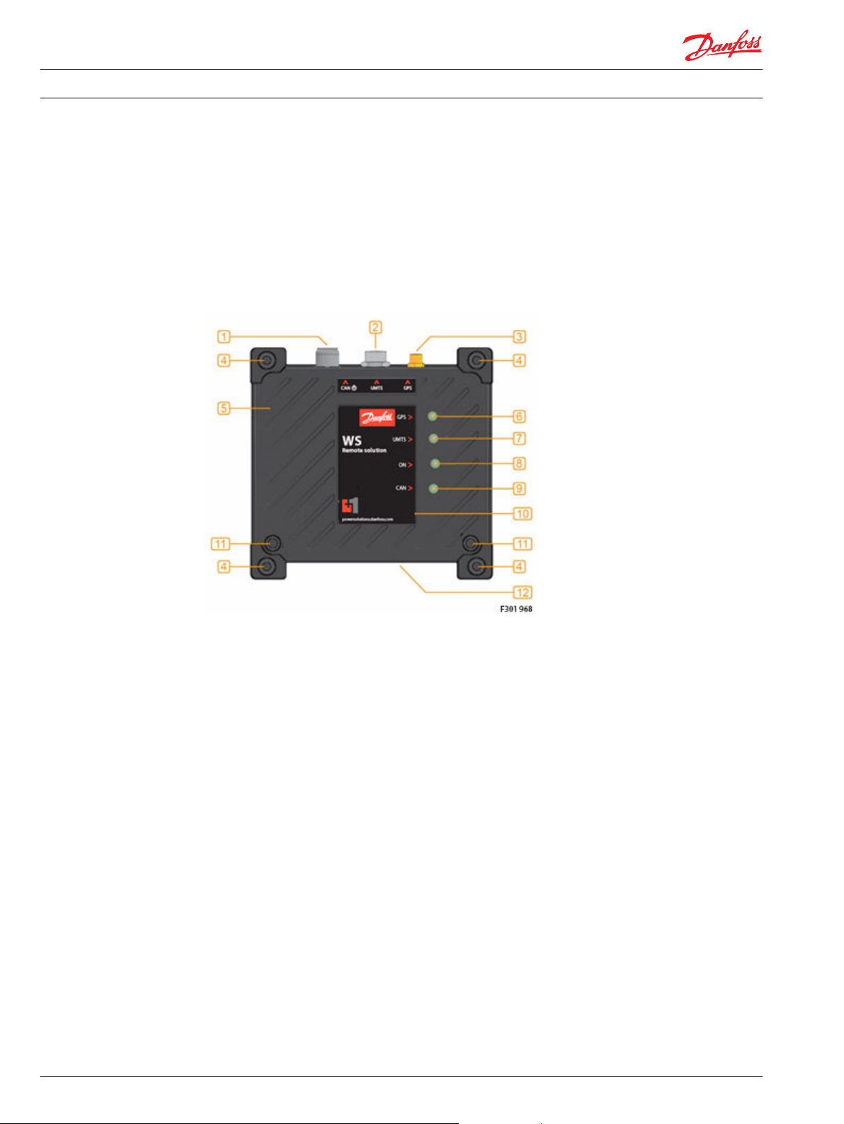
The device elements WS 403 is showed in the figure below:
WS unit
1. 'Power/CAN connector'
2. GSM/3G connector
3. GPS connector
4. Mounting holes
5. Aluminum enclosure
6. GPS LED
7. GSM/3G LED
8. ON LED
9. CAN LED
10. Front label
11. Enclosure screws
12. Type label
The Danfoss Telematics WS unit is a GSM/GPRS/UMTS modem, with or without GPS and integrated CAN
gateway for direct connection to a control system. Machine data is either transferred to the programming
or diagnostic system of the machine manufacturer or is buffered on a server.
10 L1419125 • Rev BC • January 2015
Page 11
Installation Guide
WS 403 Remote Solution
Requirements for setting up WS 403 unit
To configure the WS 403 unit, it is necessary to connect to the unit’s CAN network with a computer that
has the “WS System Tool” software installed, and has a suitable CAN gateway such as the Danfoss CG150.
Wiring
Connectors
One of the most important things to consider when installing access control hardware, is the type of
cable to be used for connecting together each component of the system.
Incorrect selection or wiring of such cables can cause a wide range of problems, including erratic or nonexistent communication, an increased danger of component damage due to transient voltages, or an
increased chance of EMI (Electro Magnetic Interference), all of which can have an adverse effect on the
installation. Refer to the Danfoss WS 403 Remote Solution Technical Information for this unit for
information on a suitable cable to use.
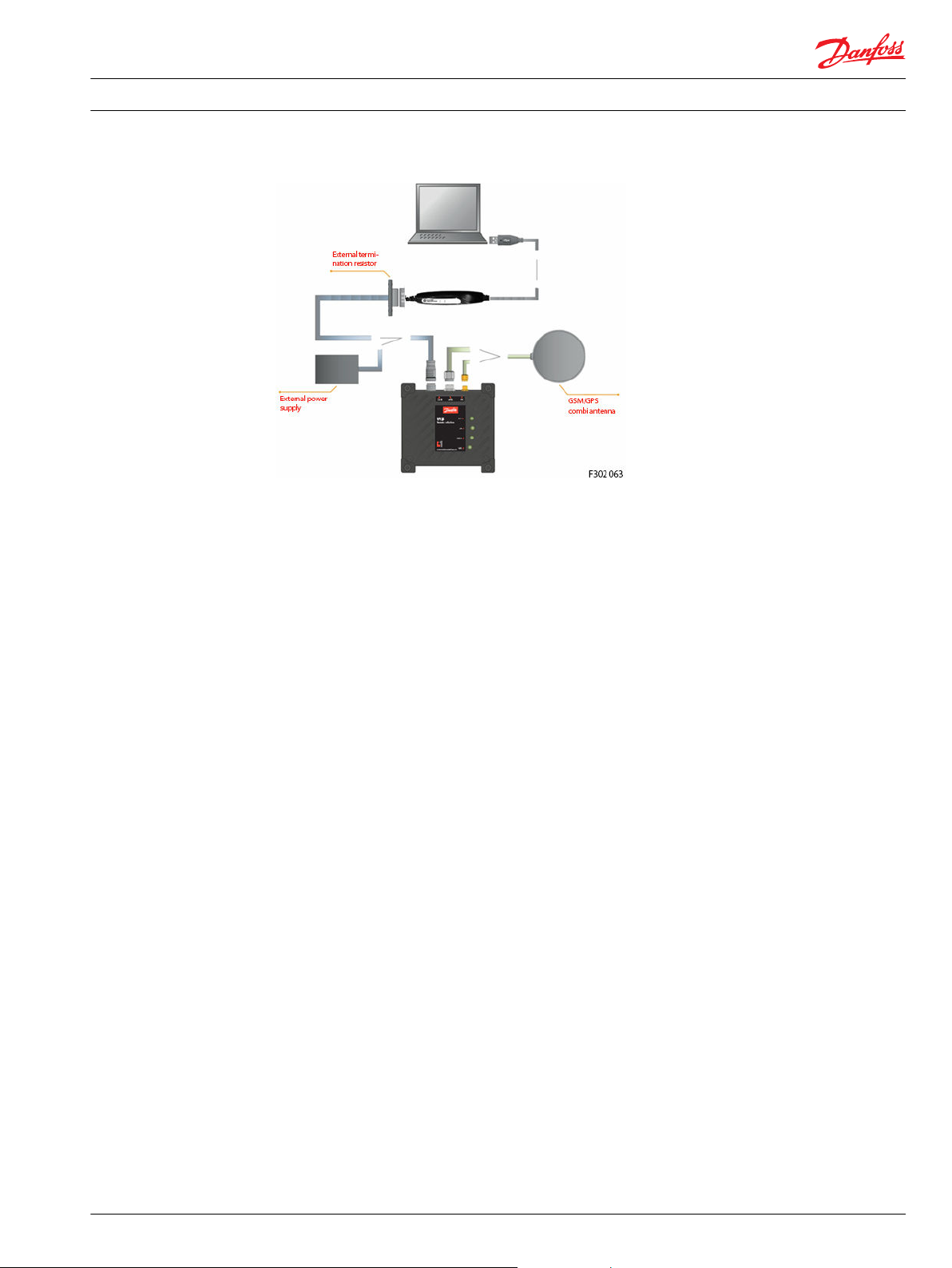
The following section describes how to connect the device with the components contained in the
Starter/Product Kit.
Using incompatible accessories may damage your equipment.If you are using other accessories than
those contained in the Starter Kit, make sure that they are compatible with the WS devices.
In order to perform the initial configuration steps, connect the device to your PC as indicated in the
image above.
The signals on the CAN connection terminals CAN-Low and CAN-High must match the signals on the CAN
terminals of the connected devices. GND of the CAN connector must be connected to CAN-GND.
WS403 is equipped with the following connectors:
•
1x Main connector
•
1x GSM connector
•
1x GPS connector
Main connector
The main connector serves for
•
connecting the WS device to the CAN bus network
•
supplying the WS device with power
Therefore, WS403 has to be connected to the CAN bus network in order to operate.
L1419125 • Rev BC • January 2015 11
Page 12
W
5
21
4
3
P301 764
P301 765
2
1
P301 766
2
1
Installation Guide
WS 403 Remote Solution
Requirements for setting up WS 403 unit
Warning
Do not connect the housing to Ground externally. This will suspend the reverse voltage protection of
•
the power supply. Applying a reversed voltage in this case will destroy the supply circuits.
To avoid damage to the device, connect/disconnect the main connector only if the power supply to
•
the device is switched off.
To maximize the performance of the GPS receiver, mount the GPS antenna in a place where it is level
•
with the local geographic horizon and has full view of the sky above. If you are using separate
GSM/3G and GPS antennas, mounting them at least 2 meters away from each other will also help to
improve the GPS performance.
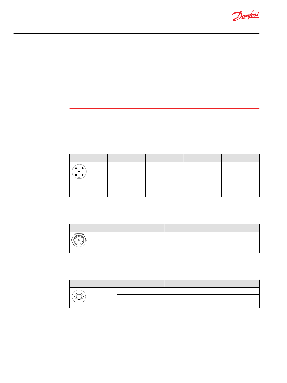
5-pin M12 CAN/power connector
The table and drawing below show the pin assignment of the 5-pin M12 connector. The colors stated in
the table below are the conductor colors of the cable listed in the section Accessories and provided in the
WS Kit.
CAN/power connector 5-pin M12, male, A-coded, front view
Pin Designation Color Description
1 Ground Brown Power supply
2 VCC 6 … 32 V DC White Power supply
3 n.c. (not connected) Blue
4 CAN-High Black CAN
5 CAN-Low Grey, green CAN
Connect antennas
GSM/3G connector
GSM/3G connector FME, male, front view
Pin Designation Description
1 Signal GSM/3G
2 Ground Shield/housing
GPS connector
GPS connector SMA, female, front view
Pin Designation Description
1 Signal GSM/3G
2 Ground Shield/housing
Danger due to absorption of RF energy
Mobile communication devices may pose a health risk when operated in the close proximity of persons.
12 L1419125 • Rev BC • January 2015
Page 13

Installation Guide
WS 403 Remote Solution
Requirements for setting up WS 403 unit
•
Install the antenna(s) used for the WS devices to provide a separation distance of at least 20 cm [8
inches] from all persons.
•
Do not operate them in conjunction or co-locate them with any other antenna or transmitter.
Operation without antennas connected can destroy the radio modem.
•
Do not operate WS device without antenna(s).
•
To avoid damage to the WS device, connect/disconnect the antenna(s) only if the power supply to
the device is switched off.
•
Do not mount the antenna(s) inside enclosed metal constructions such as driver cabins because of
the Faraday cage effect.
•
Do not shorten or lengthen the cable of the antenna(s).
GSM/3G antenna
•
Make sure that the device’s power supply is switched off.
•
Connect the GSM/3G/GPS combo antenna FMA connector to the device’s GSM/3G connector.
GPS antenna
Use only active GPS antennas with LNA, gain max. 25 dBi, voltage 3 V DC, current max. 30mA.
•
Make sure that the device’s power supply is switched off.
•
Connect the antenna’s SMA connector to the device’s GPS connector.
Connect CAN gateway and PC
CAN bus termination
Connect power supply
To maximize the performance of the GPS receiver, mount the GPS antenna in a place where it is level with
the local geographic horizon and has full view of the sky above. If you are using separate GSM/3G and
GPS antennas, mounting them at least 2 meters away from each other will also help to improve the GPS
performance.
After connecting the antennas, establish a connection to a laptop via a gateway device by Danfoss
CG150.
Before connecting the Danfoss CG150 to the laptop, you need to install the gateway driver.
In each CAN bus system, signal reflections at the end of a wire or cable can cause interference which is
one reason for transmission errors. As requires by industry standards, a terminating resistor must be
installed at each end of the CAN backbone. This terminator has to match the characteristic impedance of
the transmission line.
In CAN bus networks, normally unshielded twisted pair cables are used for signal transmission. These
cables have a characteristic impedance of approximately 120 Ohms. Thus a resistor of 120 Ohms has to
be placed at each end of the CAN bus line between CAN-High and CAN-Low to reduce the reflections and
enable correct communication.
Before connecting power to the WS device, assure that both antenna wires are connected. For pinout of
the power and CAN cable, refer to Connectors on page 11. When powering this device from a power
supply rather than a battery, assure that the power supply is capable peak currents of 2 amps and at least
9 volts.
L1419125 • Rev BC • January 2015 13
Page 14
Installation Guide WS 403 Remote Solution
Requirements for setting up WS 403 unit
Initial configuration
After connecting all components as described above, you need to perform some initial configuration
steps with the help of the WS System Tool.
The initial configuration requires a physical connection to the PC. To configure the SIM card see Configure
SIM Card on page 27.
With real-time access, if the SIM card is already configured, you will also be able to configure the device
remotely via an Internet connection by using the WS Configurator tool.
Indicator elements
The device is equipped with the following indicator elements:
•
1x CAN multicolor LED
•
1x ON multicolor LED
•
1x GSM/3G multicolor LED
•
1x GPS multicolor LED
If green and red colors are simultaneously on, the LED will appear orange.
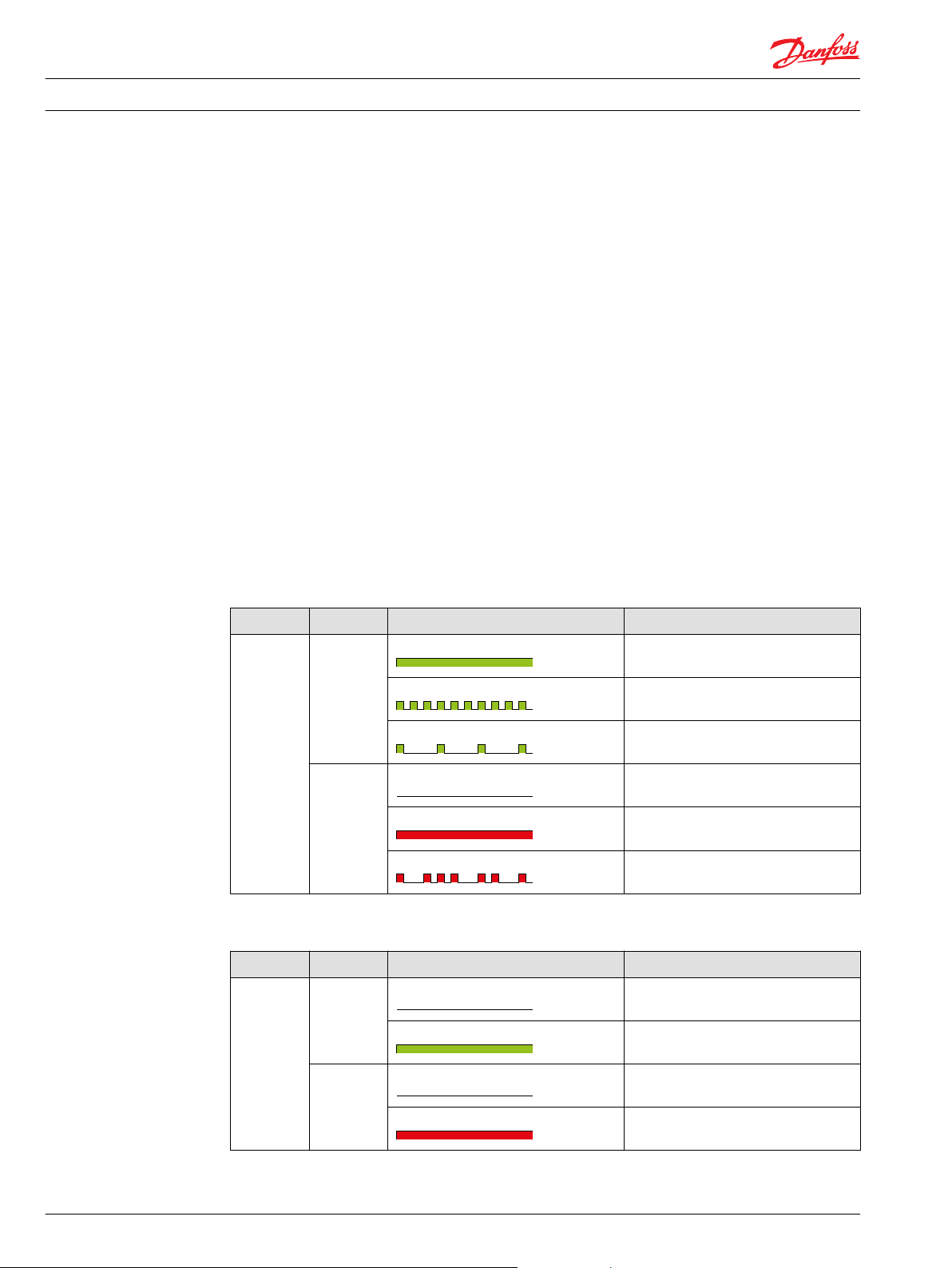
The following tables describe the LED light characteristics and the corresponding device status.
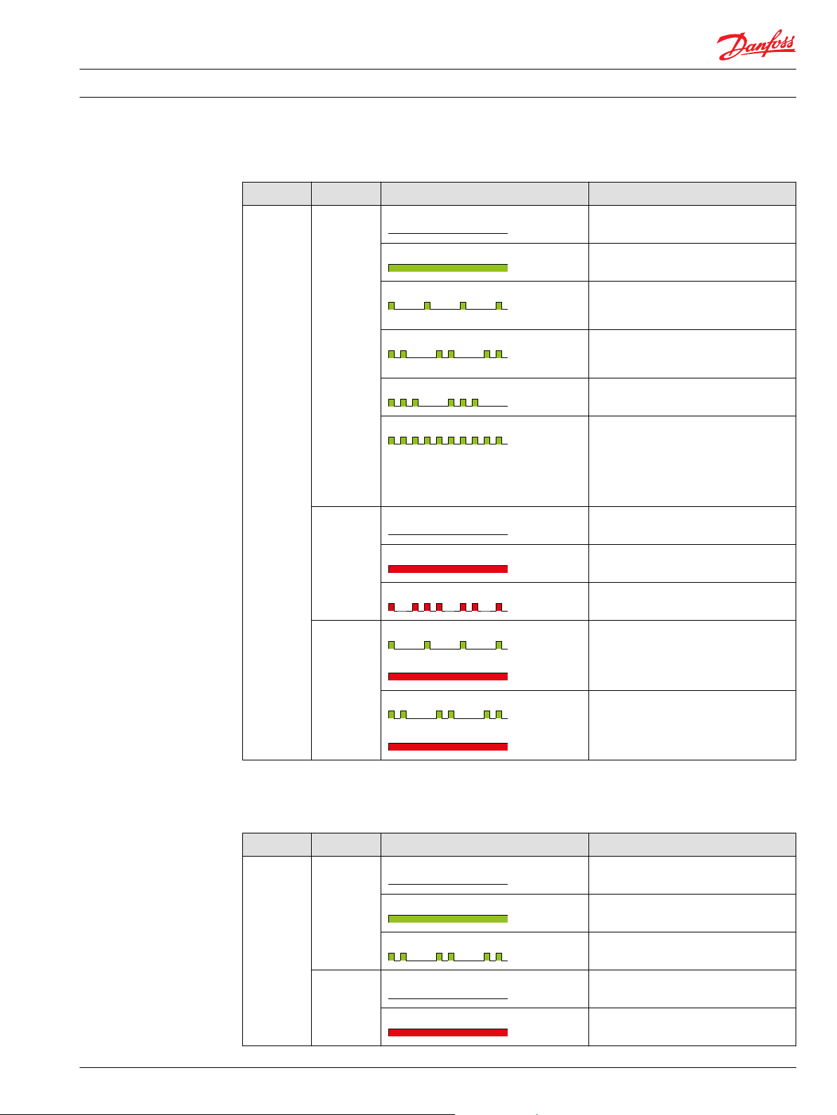
CAN LED states
LED Color Light characteristics Description
CAN green constantly on CANopen NMT status operational
blinking CANopen NMT status preoperational
single flash CANopen NMT status stopped
red off No CAN data receiving/ sending
constantly on CAN error (i.e. bus-off)
flashing irregularly CAN data receiving/sending
ON LED states
LED Color Light characteristics Description
ON green off No power supply or outside specified
on Power supply inside specified values
values constantly
red off -
constantly on Power supply outside specified values
14 L1419125 • Rev BC • January 2015
Page 15
Installation Guide WS 403 Remote Solution
Requirements for setting up WS 403 unit
GSM/3G LED states
LED Color Light characteristics Description
GSM/ 3G green off -
red off No TCP/IP data over the air receiving/
constantly on Connected to a server, TCP/IP active
single flash Connecting to a server If double flash does
not change into continuously on: No data
card OR Antenna faulty
double flash Initialization status of GSM/3G engine If
double flash does not change into
continuously on: Antenna faulty
triple flash Reset status of GSM/3G engine
blinking Idle status of GSM/3G engine, the device is
ready to connect to a server. If blinking
does not change into continuously on:
Device not registered OR Online Mode
Handling not set to “always connect to
server”
sending
constantly on Fatal GSM/3G error (i.e. no SIM card
inserted)
flashing irregularly TCP/IP data over the air receiving/sending
first green,
then red
green single flash
then red constantly on
green double flash
then red constantly on
Code repeated: GPRS provider settings not
correct, e.g. APN
Wrong PIN If this code is repeated: No
SIM / SIM faulty OR GSM module faulty
GPS LED states
(Models with GPS functionality only)
LED Color Light characteristics Description
GPS green Off GPS is disabled
constantly on Valid GPS data available
double flash No valid GPS data available
red off GPS antenna OK
constantly on GPS antenna error (missing or short
circuited)
L1419125 • Rev BC • January 2015 15
Page 16

W
Installation Guide WS 403 Remote Solution
Requirements for setting up WS 403 unit
Warning
If all LEDs are constantly green at the same time and synchronously flashing red (so all LEDs blinking
orange), the device is in firmware update mode.
Do not switch the device off.
•
16 L1419125 • Rev BC • January 2015
Page 17

Installation Guide WS 403 Remote Solution
WS system tools
WS System Tools is a group of tools that can be used to configure and upgrade the firewall of the WS 403
device.
L1419125 • Rev BC • January 2015 17
Page 18
Installation Guide
WS configurator tool
WS 403 Remote Solution
The first step is to define the communication between the PC and the CAN adapter and the remote
communication unit.
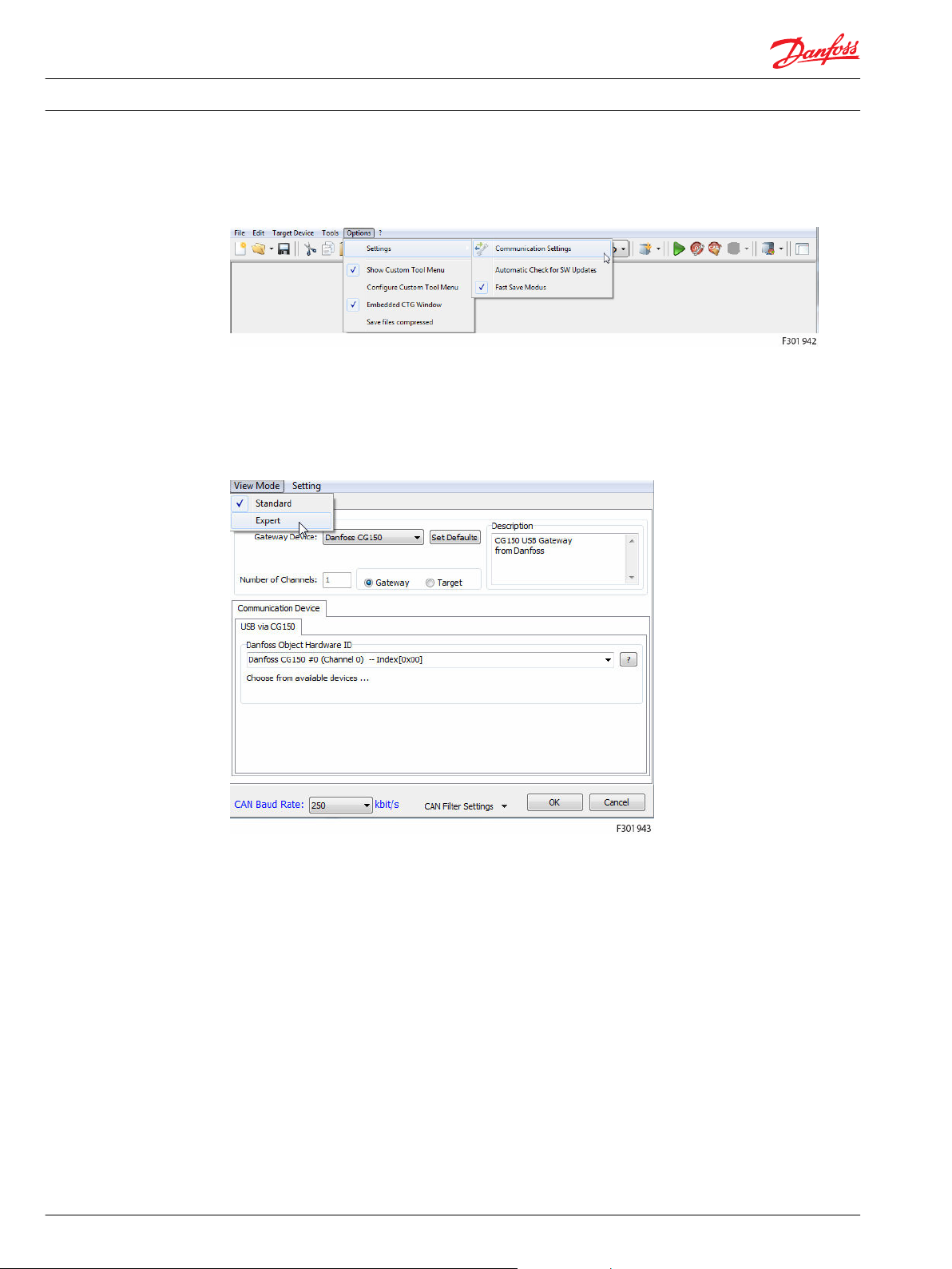
In the WS Configurator main window, select
•
Options > Settings > Communication Settings.
The Communication Settings window opens.
This window has two different view modes: Standard or Expert view mode.
For the initial configuration, it is essential to ensure the following settings in the expert view mode.
To switch to expert view mode, select View
•
Mode > Expert
18 L1419125 • Rev BC • January 2015
Page 19
Installation Guide WS 403 Remote Solution
WS configurator tool
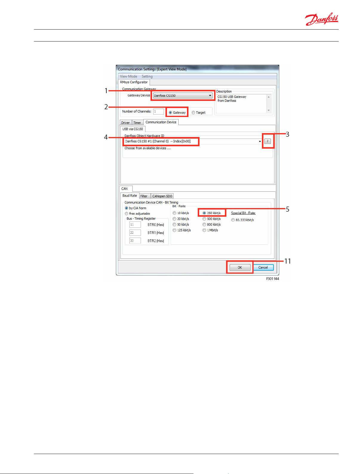
1. Select the appropriate CAN bus gateway: Danfoss CG150
2. Select the Unit as Gateway
3. To view a list of available Danfoss Object Hardware ID, click the question mark.
4. From this list, select the corresponding Danfoss CG150 #1 (Channel 0) --Index[0x00].
5. Set the CAN Baud Rate according to your system. The default value is 250 kbit/s.
L1419125 • Rev BC • January 2015 19
Page 20
Installation Guide WS 403 Remote Solution
WS configurator tool
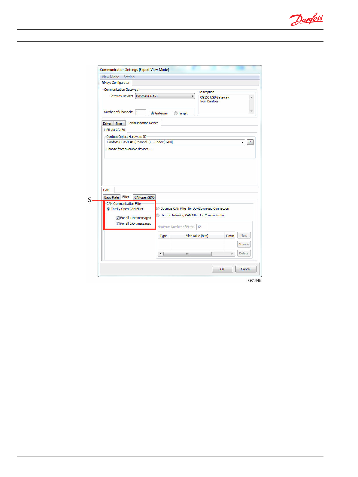
6. In the Filter tab, select Totally Open CAN Filter and tick For all 11-bit messages and For all 29-bit
messages.
20 L1419125 • Rev BC • January 2015
Page 21
Installation Guide
WS configurator tool
WS 403 Remote Solution
Perform node scan
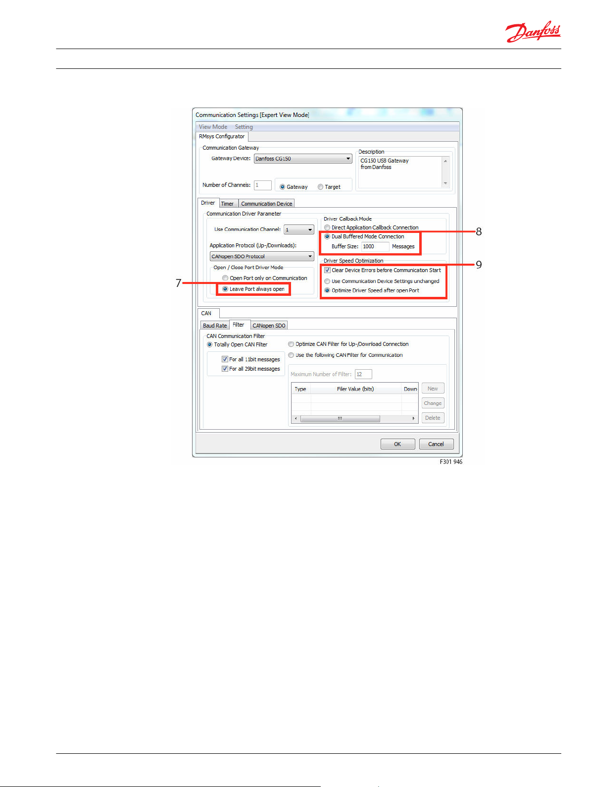
7. Select Leave port always open.
8. Select Dual buffered mode connection and set the buffer size to 1000 messages.
9. Select Clear device errors before communication start and Optimize driver speed after open port.
10. Leave all other settings at default.
11. To accept and finish the configuration, click OK
To check the connection to the remote connectivity device, perform a node scan.
L1419125 • Rev BC • January 2015 21
Page 22

Installation Guide
WS configurator tool
WS 403 Remote Solution
Select Tools > Node Scan in the main menu.
Alternatively, you can click the corresponding icon in the main window’s tool bar:
A window opens, listing the connected CAN devices, their CANopen node-IDs, product codes, and
information on hardware and software versions:
1. Select the remote connectivity device you wish to configure
2. click -> Close.
In the WS Configurator main tool bar, you will see the product code and the node-ID of the device you
are going to configure:
22 L1419125 • Rev BC • January 2015
Page 23

Installation Guide
WS configurator tool
Adapt demo configuration file
WS 403 Remote Solution
WS Configurator software includes several demo configuration files for WS devices. These files are in DOD
format and contain an object dictionary with the most common basic settings. However, some changes
may be required, depending on your individual application.
You may change some settings, such as the roaming settings or the online mode handling, to better suit
your application.
If you are using a different SIM card, the following changes are required:
•
Select a GSM/3G network provider.
•
Change the default SIM card PIN.
It is further recommended to:
•
Check the roaming settings.
•
Check the online mode handling options.
To adapt the demo configuration, proceed as follows: WS Configurator must be running and the devices
connected as described in the previous sections (with CG150 connected to the WS unit).
To open a demo configuration file:
1. click the arrow at the right hand side of the folder icon in the tool bar
2. select Demo configuration files
The software automatically opens the path where the demo configuration files are installed.
Access the Demos folder, select your WS model and open a related DOD file, e.g. a real-time mode
configuration.
L1419125 • Rev BC • January 2015 23
Page 24

Installation Guide
WS configurator tool
WS 403 Remote Solution
WS Configurator loads the selected demo configuration.
You will also see a description of the demo settings in a separate window.
24 L1419125 • Rev BC • January 2015
Page 25

Installation Guide
WS configurator tool
WS 403 Remote Solution
Select File > Save as and save the DOD file you are going to modify under a new name, so that you will
keep the provided demo file in its original configuration.
L1419125 • Rev BC • January 2015 25
Page 26

Installation Guide WS 403 Remote Solution
WS configurator tool
In the main window, the software distinguishes between application-related variables and special
security variables, related to the connection between the CAN adapter and the remote connectivity
device and Web Portal. These variables are listed in the Application or Specials tab respectively.
At this stage, it is not required to modify the default application-related variables in the Application tab.
You can just download them to the device.
To download the application variables to the device:
1. Make sure that the Application tab is activated as in the picture above.
2. click the download all Entries icon in the tool bar.
1. Click Start to start the download to the device.
2. Download finish successful if the last bar graph is colored in green.
3. Click on protocol to obtain the report about the download process..
26 L1419125 • Rev BC • January 2015
Page 27

Installation Guide
WS configurator tool
Configure SIM Card
WS 403 Remote Solution
To access the connection-related security variables, select the Specials tab. A yellow frame around the
object dictionary window indicates that the Specials tab with the security variables is activated.
In the Object Dictionary- Secured Entry section, click Security Variables to open the variables tree.
L1419125 • Rev BC • January 2015 27
Page 28
Installation Guide
WS configurator tool
WS 403 Remote Solution
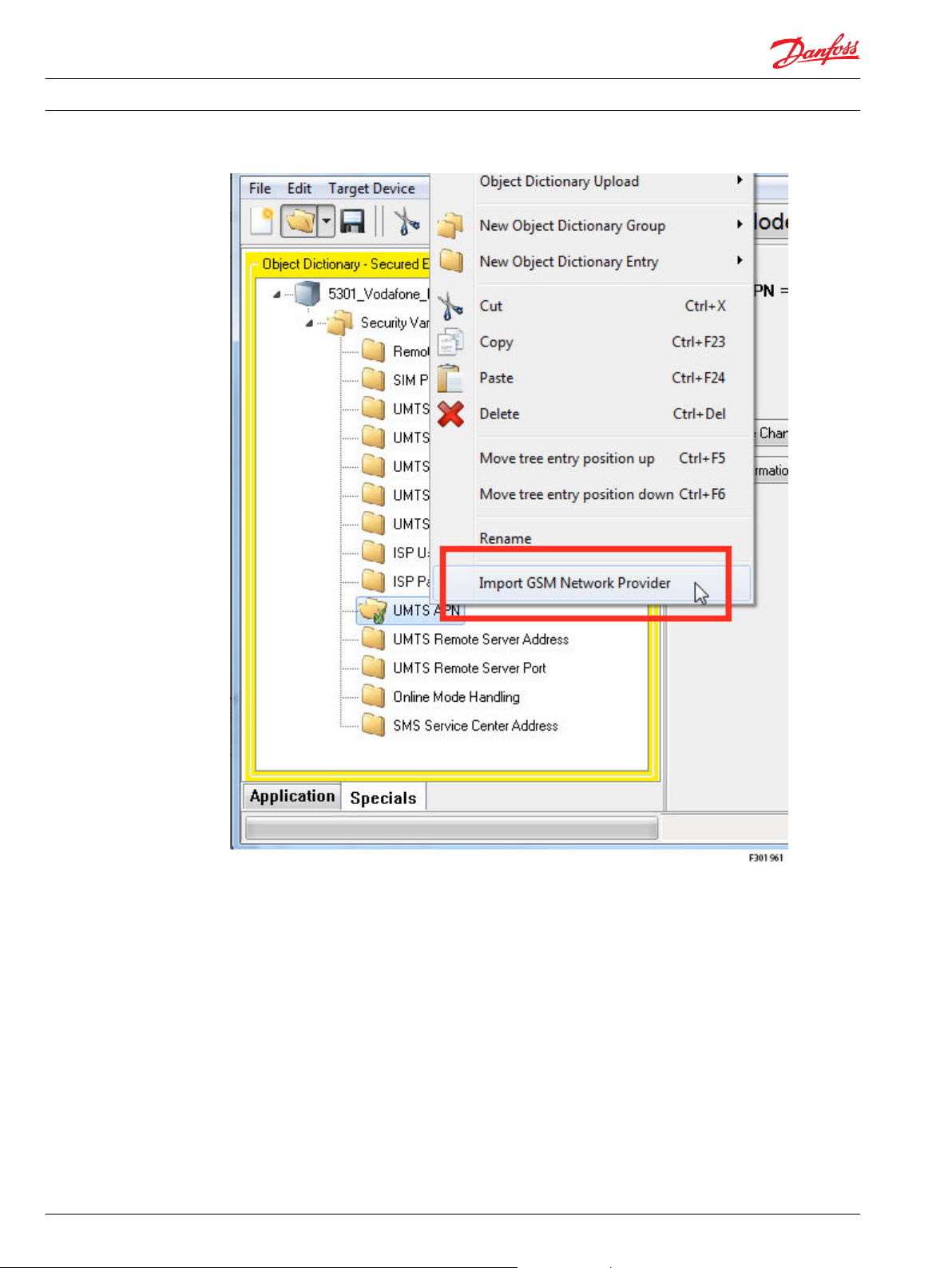
Right-click anywhere inside the object dictionary window, e.g. on the DOD name, and select Import GSM
network provider.
The software opens a list with network providers, indexed by countries. This list is updated automatically
via the Internet at each import.
28 L1419125 • Rev BC • January 2015
Page 29

Installation Guide
WS configurator tool
WS 403 Remote Solution
1. Select your country
2. Select network provider
3. click the Select button to confirm all the network provider variable values
In the Object Dictionary-Secured Entries section, click Security Variables to open the variables tree and
select SIM PIN to change the SIM card PIN settings.
If required, change the default PIN (2304) to the PIN of the actually deployed SIM card. If the PIN is not
activated, leave this field blank. Make sure to insert the correct PIN. It is not possible to change the preset
SIM card PIN with the WS unit. To check the roaming settings, select GSM Roaming Handling. To disable
roaming, set the value to 0; to enable roaming, set it to ≠ 0. In the default settings, roaming is disabled. To
check the connection options, select Online Mode Handling. With the default settings, the device
automatically establishes a connection to the Web Portal server after power up. If you wish to change
this, set the bit according to the information given in the software.
Check the Remote Access Password variable value, must be equal to ‘GSMONLIN’.
L1419125 • Rev BC • January 2015 29
Page 30

Installation Guide
WS configurator tool
WS 403 Remote Solution
To download the settings to the device, click the Download all entries icon in the tool bar.
Make sure that the Security Variables are activated as shown in the figure above, otherwise, the software
will not download the security variables. A window opens requesting you to confirm that you want to
modify ‘critical parameters’, that is parameters concerning the communication with Web Portal.
Click Yes to confirm Click
Start to start the download to the device.
30 L1419125 • Rev BC • January 2015
Page 31

Installation Guide
WS configurator tool
WS 403 Remote Solution
Wait until the download is finished (download finish successful if the last bar graph is colored in green).
Click on Protocol to obtain the report about the download process.
Safety functions settings
Starting with the FW version 9.09 or above the WS devices include the safety function settings in the
related DOD configurator files. Open the file ‘WS Danfoss Telematics Remote Safety.DOD’. If the following
pop up window appear, press OK.
In the Application tab, Object Dictionary section, click Interface Variables > Remote Safety Variables to
open the variables tree.
L1419125 • Rev BC • January 2015 31
Page 32

Installation Guide
WS configurator tool
WS 403 Remote Solution
Remote safety function active
The allowed values of this variable are:
0 Full free access of read and write to the remote application
≥1 Limited access to the remote application active, read of data is not limited.
See all “Remote Safety” variables for details configuration. (default setting value).
To disable the remote safety function, set the variable to 0, press download, and power off the device.
Remote safety CAN identifier
The Remote safety CAN identifier can be 11-bit or 29-bit, the type codes:
32 L1419125 • Rev BC • January 2015
Page 33

Installation Guide WS 403 Remote Solution
WS configurator tool
•
Bit 29 = 0: 11-bit type
•
Bit 29 = 1: 29-bit type
•
Bits 0 to 28: CAN identifier
Remote safety start Byte position in CAN message
The Remote Safety Start-Byte-Position in configured CAN Message has the following range of validity:
Range: 0 .. 7
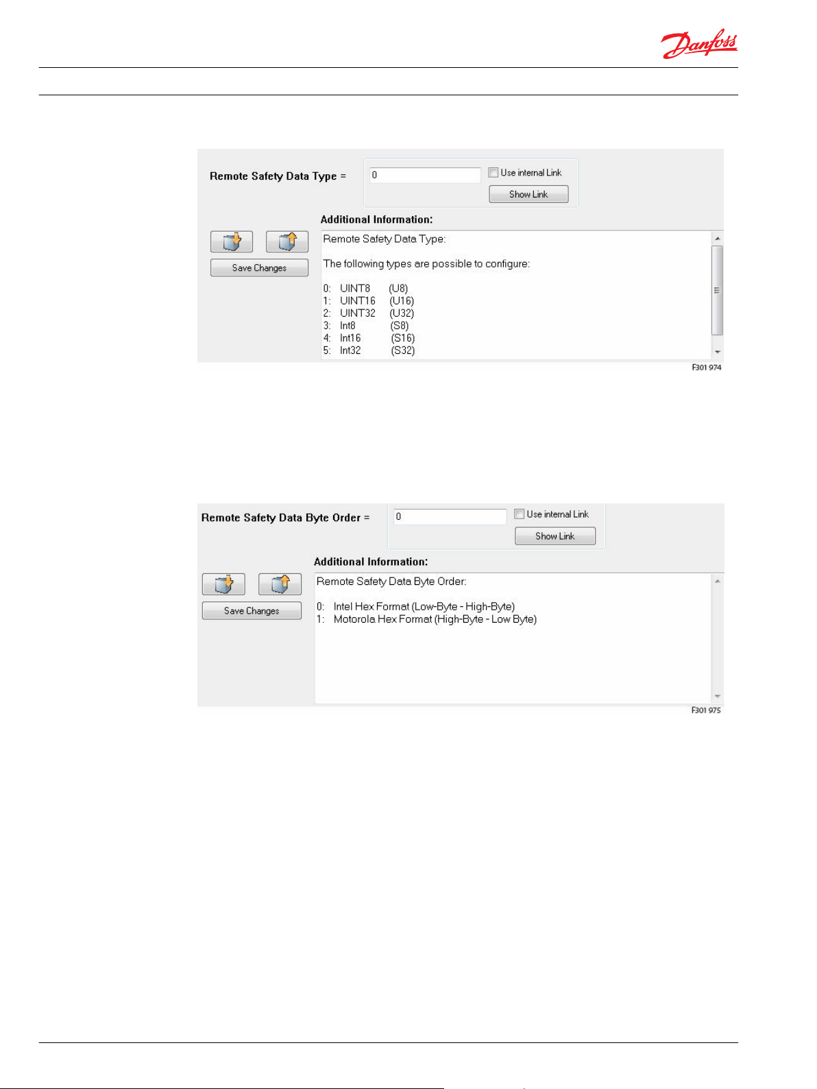
Remote safety data type
The following types are possible to configure for the Remote Safety CAN message:
0: UINT8 (U8)
1: UINT16 (U16)
2: UINT32 (U32)
3: Int8 (S8)
4: Int16 (S16)
5: Int32 (S32)
L1419125 • Rev BC • January 2015 33
Page 34
Installation Guide WS 403 Remote Solution
WS configurator tool
Remote safety data byte order
Remote Safety Data Byte Order available:
0: Intel Hex Format (Low-Byte - High-Byte) (most used)
1: Motorola Hex Format (High-Byte - Low Byte)
34 L1419125 • Rev BC • January 2015
Page 35
Installation Guide WS 403 Remote Solution
WS configurator tool
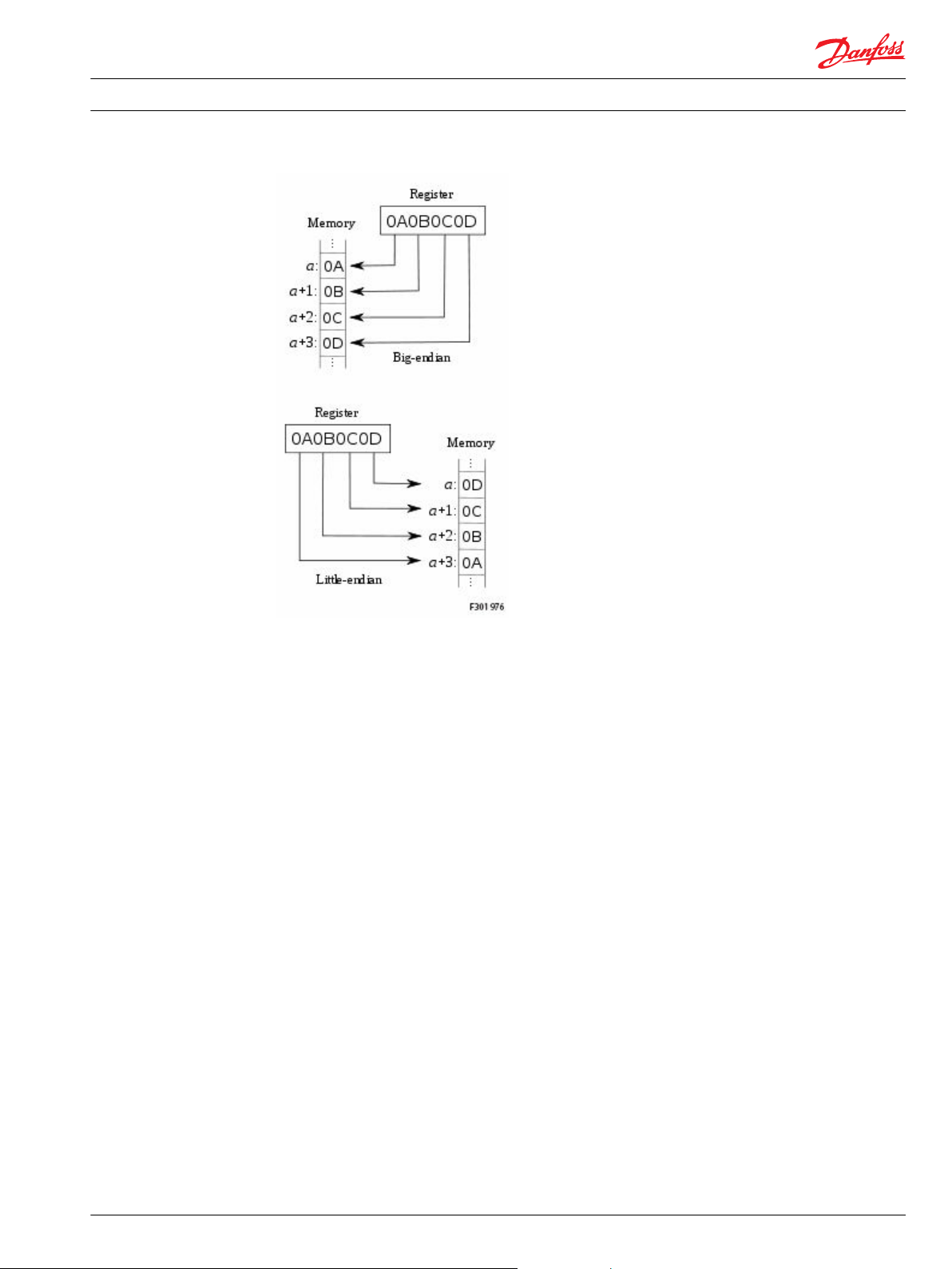
Big-endian systems store the most significant byte of a word in the smallest address and the least
significant byte is stored in the largest address.
Little-endian systems, in contrast, store the least significant byte in the smallest address.
Remote safety trigger condition
On base of this condition, incoming data can be compared with a value. The following conditions are
possible:
0: =
1: > =
2: >
3: <=
4: <
5: <> (unequal)
L1419125 • Rev BC • January 2015 35
Page 36

Installation Guide
WS configurator tool
WS 403 Remote Solution
Remote safety compare value U8, U16, U32, S8, S16, S32
Is the value compared with the Safety CAN Msg read on CAN bus network using the condition selected: if
the condition is true the WS unit switch automatically in Read Only mode.
Remote safety time out
The Safety CAN message must be configured in the control system and sent cyclic on CAN bus.
This value is a multiple of 10 ms: Timeout = value * 10ms
If this value is set to zero, the timeout control is switched off.
36 L1419125 • Rev BC • January 2015
Page 37

Installation Guide
WS configurator tool
SIM card details
WS 403 Remote Solution
The SIM card format recommended to be used with WS device is 2FF (3FF or 4FF with adapters).
The services required are indicated in the following table:
Services Required
SMS Yes
CSD/HSCSD No
Voice No
2G GSM/GPRS/EDGE Yes
3G UMTS/HSDPA Yes
4G LTE No
Roaming Yes
How to install and setup a SIM card in a WS 403 unit
The installation and setup of a SIM card for a remote connectivity unit needs to be done in two steps. The
first step is the mechanical mounting of the SIM card on the remote connectivity unit and the second
step is the software configuration of the RMC unit with the SIM card specific data.
Open the unit
The remote connectivity unit is strewed with 4 torx head screws size T15. There are two screws on the
front and two screws on the back of the unit.
Do not open the housing if remote connectivity unit is switched on. Switch off the power supply to
connectivity unit first and then disconnect the power supply/CAN connector.
L1419125 • Rev BC • January 2015 37
Page 38

Installation Guide
WS configurator tool
WS 403 Remote Solution
The maximum torque for fixing the enclosure screws is 1.5 Nm. When opening/closing the enclosure, do
not exceed this value. Only open the enclosure in a clean environment so that no dust or fluid can get
inside.
Do not touch the PCB nor the components mounted on the PCB, they may be damaged by electrostatic
discharge (ESD).
Scratches and bending can cause damage to the SIM card. Do not bend the card nor touch the contacts.
Do not bend the card nor touch the contacts. The SIM card’s operating temperature may differ from the
device specifications.
Contact the SIM card provider for the acceptable temperature range.
Remove the 4 screws and open the unit
Lift the back lid to open the enclosure.
If the back lid sticks to the seal and the front half, carefully insert a screw driver between the two halves to
affect leverage.
You can now access the SIM card holder located in the lower left corner of the PCB. To avoid damage due
to Electro Static Discharge (ESD), do not touch the PCB nor the components mounted to the PCB. To
unlock the SIM card slider press the yellow bottom on the left side of the socket
Remove the SIM card slider from the socket.
38 L1419125 • Rev BC • January 2015
Page 39

Installation Guide
WS configurator tool
WS 403 Remote Solution
1. Insert the SIM-Card into the slider.
2. Place the slider back into the socket.
3. Look the SIM card slider into the SIM card socket.
Put the two parts of the housing together and mount the four screws to close the housing.
L1419125 • Rev BC • January 2015 39
Page 40
Installation Guide
WS FW programmer tool
WS 403 Remote Solution
The first step is to define the communication between the PC and the CAN gateway (CG150) and the WS
unit.
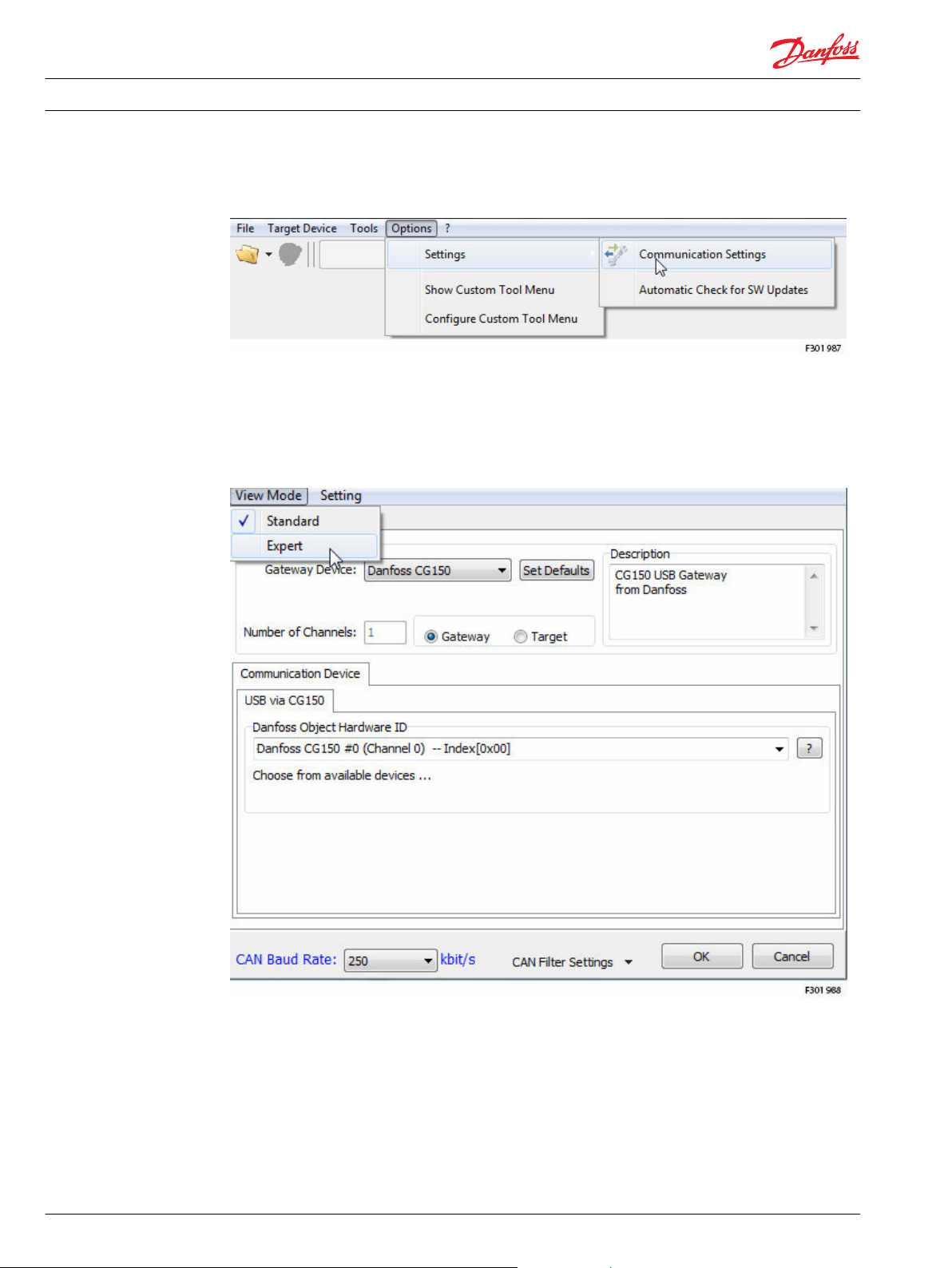
In the WS FW Programmer main window, select
•
Options > Settings > Communication Settings
The Communication Settings window opens.
This window has two different view modes: Standard or Expert view mode. For the initial configuration, it
is essential to ensure the following settings in the expert view mode.
To switch to expert view mode, select
•
View Mode > Expert
40 L1419125 • Rev BC • January 2015
Page 41

Installation Guide
WS FW programmer tool
WS 403 Remote Solution
Open the WS FW file
1. Select the appropriate CAN bus gateway: Danfoss CG150.
2. Select the Unit as Gateway.
3. To view a list of available Danfoss Object Hardware ID, click the ? question mark.
4. From this list, select the corresponding Danfoss CG150 #1 (Channel 0) --Index[0x00].
5. In the tab Baud Rate set the Bit-Rate according to your system. The default value is 250 kbit/s.
6. In the tab Baud Rate select by CiA Norm.
7. To accept and finish the configuration, click OK.
To be ready to download a firmware on the WS device it’s necessary to use the WS FW Programmer and
select the firmware application file.
The WS firmware application file has an extension FwBin and are specific for each WS devices:
L1419125 • Rev BC • January 2015 41
Page 42
Installation Guide
WS FW programmer tool
WS 403 Remote Solution
•
WS 403: WS 403_UMTS_Danfoss_0909.FwBin
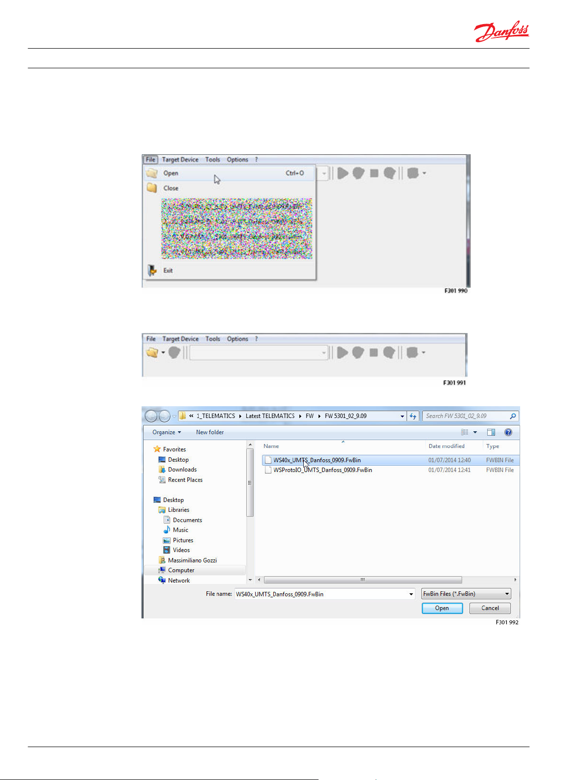
In the WS FW Programmer main window, select
•
File > Open
or
•
click in the folder icon called Open
The Open FwBin File window popup and the user can browse and select the specific firmware file:
Selected the right firmware file press Open and on the WS FW Programmer main windows appear the
firmware download setting page.
42 L1419125 • Rev BC • January 2015
Page 43

Installation Guide
WS FW programmer tool
WS 403 Remote Solution
Select the desired communication path:
L1419125 • Rev BC • January 2015 43
Page 44
Installation Guide
WS FW programmer tool
WS 403 Remote Solution
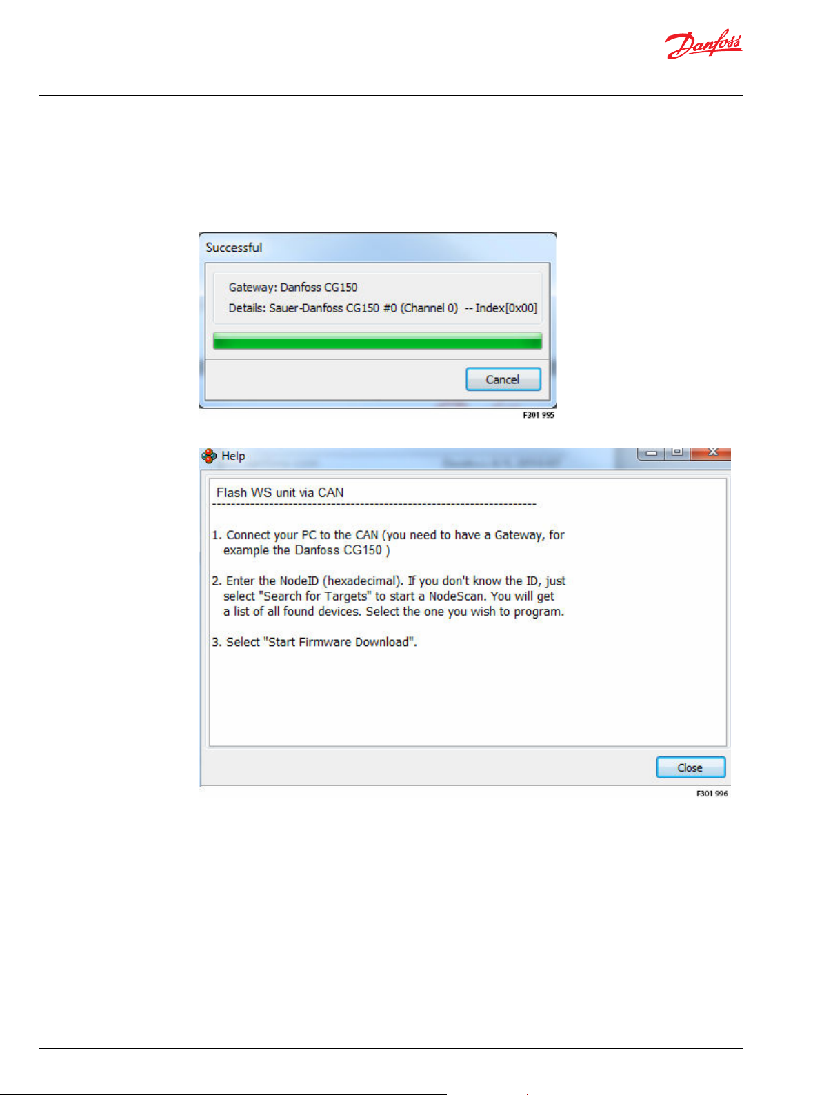
Connection via CAN
Use the CG150 Danfoss gateway in order to download the selected firmware into the WS unit (to be sure
that the gateway is already connected to a laptop).
After the selection, the communication with the Danfoss CG150 CAN bus gateway is checked.
Press ? question mark in case of help.
The Communication Path section show the settings needed by the Communication via CAN:
44 L1419125 • Rev BC • January 2015
Page 45
Installation Guide
WS FW programmer tool
WS 403 Remote Solution
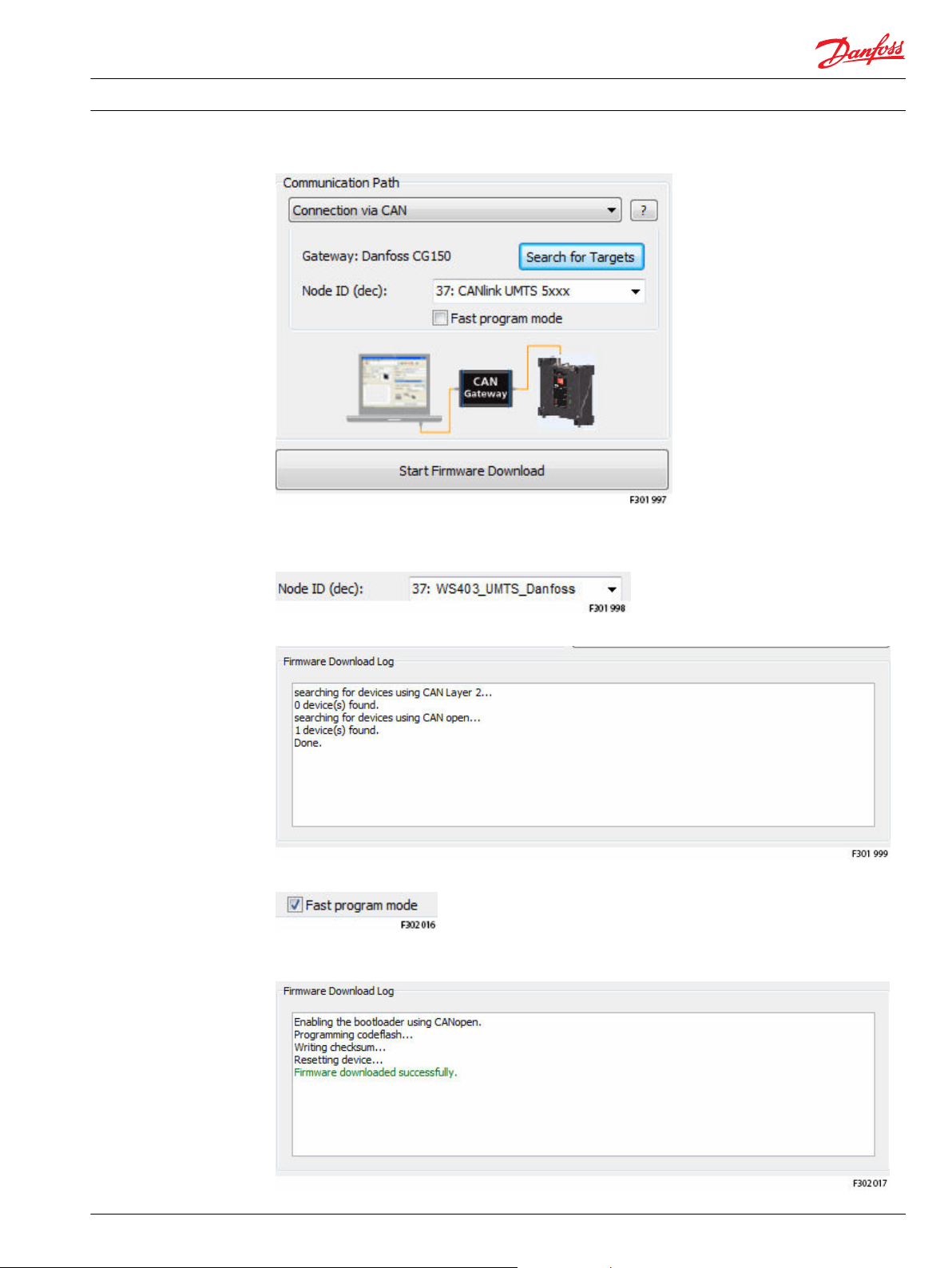
Click on Search for Targets to identify the WS node ID (to be sure that the WS unit is connected to the
CAN bus Network, the same where it is connected the Danfoss CG150), after the scan of the network the
Node ID (dec) show the Node ID of the WS unit:
In the Firmware Download Log are showed the network scan information, one CANopen unit is found:
The user can check the Fast program mode choice to speed up the firmware download via CAN.
Click Start Firmware Download push button to start the download of the firmware, on the Firmware
Download Log are showed the activity state:
L1419125 • Rev BC • January 2015 45
Page 46
Installation Guide
WS FW programmer tool
WS 403 Remote Solution
When the download is done the message ‘Firmware download successfully’ in green confirm that is done
correctly. During the download all the Led’s on the WS device blinking orange and when is finished the
WS device restart.
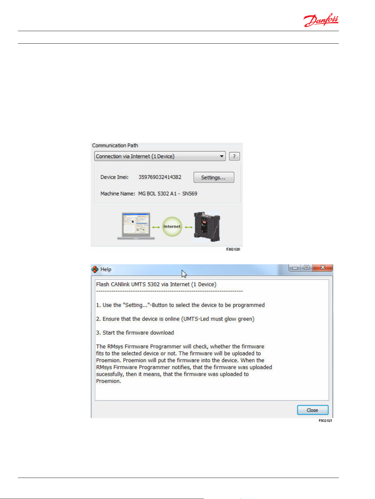
Connection via Internet (1 Device)
Use an internet connection to download the selected firmware into a selected WS unit (it’s necessary to
have the credential to Access to the Web Portal and the WS unit must be connected on the Web Portal).
After the selection, the Communication Path section show the specific settings and the information that
will be collected from the WS unit (device IMEI and Machine Name).
Press ? question mark in case of help.
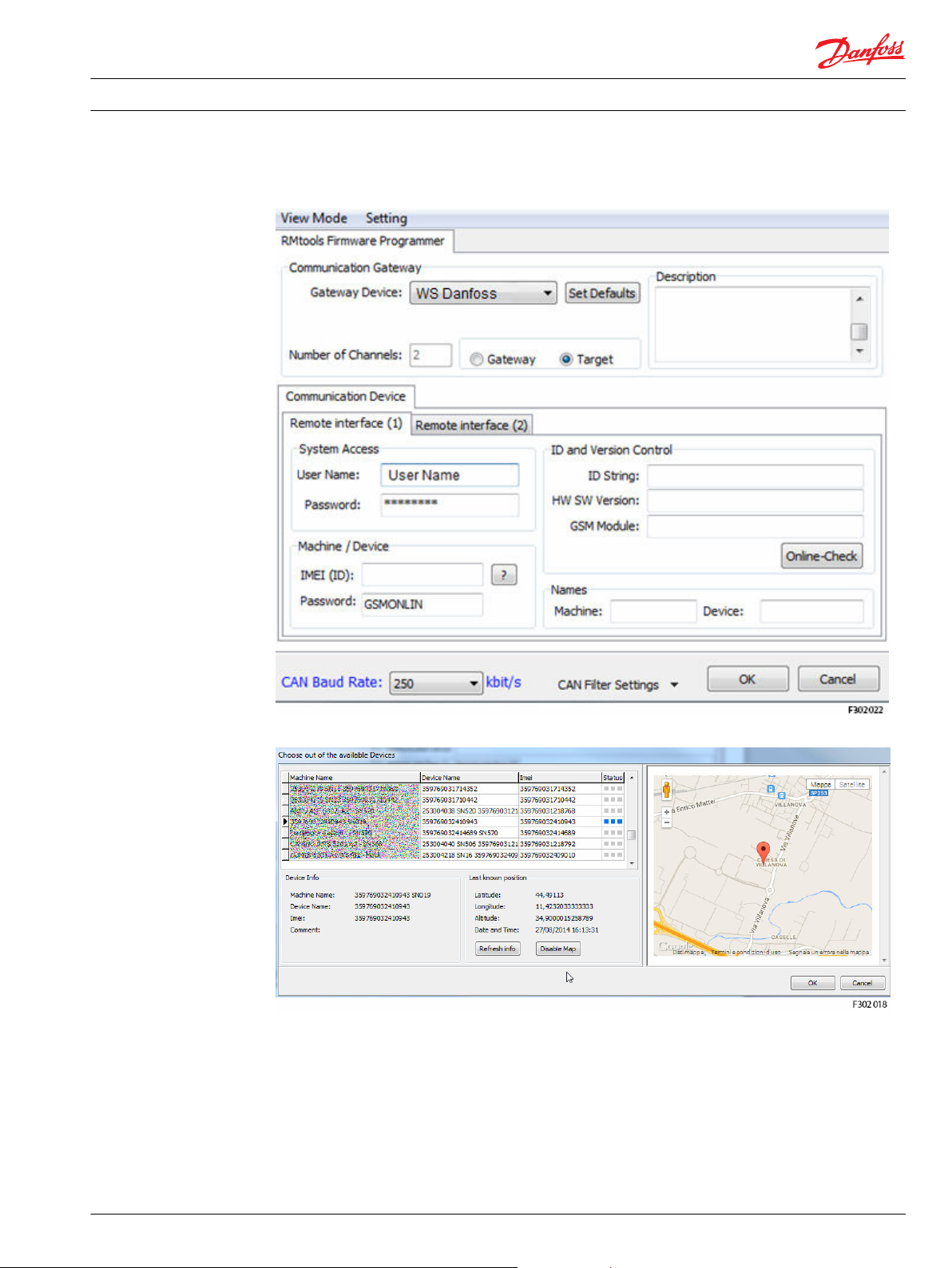
Click the Setting...’ push button to enter into the page were to configure the internet connection for the
selected WS unit. In the communication gateway section select as a Gateway Device the ‘WS Danfoss' and
select the field ‘Target’.
In the Remote Interface > System Access section use the Web Portal User Name and Password.
46 L1419125 • Rev BC • January 2015
Page 47
Installation Guide
WS FW programmer tool
WS 403 Remote Solution
In the Remote Interface > Machine/Device section the password is ‘GSMONLIN’ for all the WS unit by
default (the user can decide to change the password using the WS Configurator Tool).
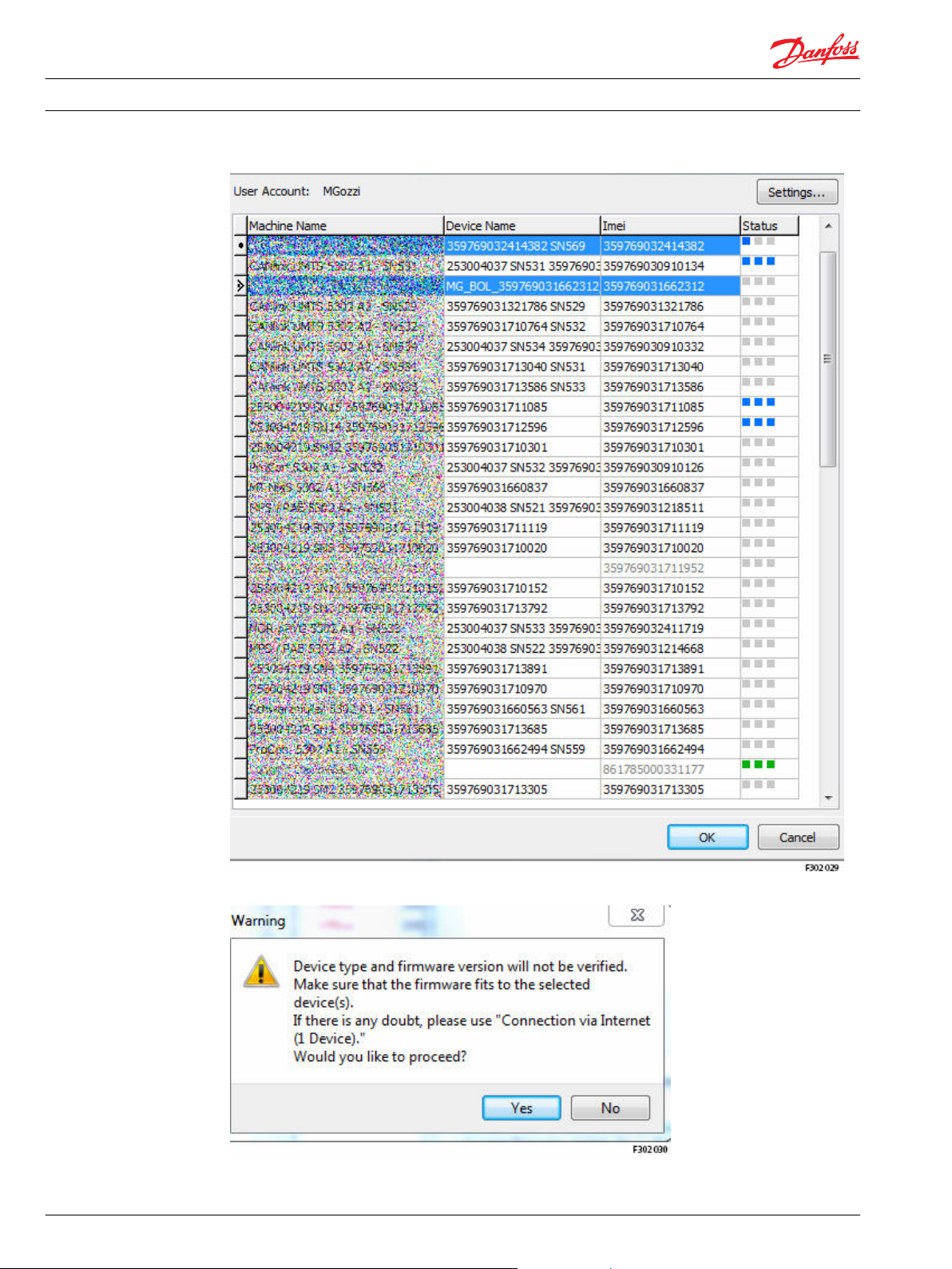
Click on ? to connect on the Web Portal and select the WS unit connected in Real Time mode:
Select the WS unit (if the WS unit has the GPS installed the user can check the position for verifications)
and press OK.
Now the IMEI (ID), the Device and Machine names are filled-in and identify the selected device.
L1419125 • Rev BC • January 2015 47
Page 48

Installation Guide
WS FW programmer tool
WS 403 Remote Solution
Press OK, the new gateway is checked:
Click Get Firmware Version push button to verify the current version of the FW installed in the selected
WS unit, the information are showed in the Firware Dowload Log section (for example FW ver. 09.07):
48 L1419125 • Rev BC • January 2015
Page 49

Installation Guide
WS FW programmer tool
WS 403 Remote Solution
Click Start Firmware Download push button to start the download of the firmware, on the Firmware
Download Log are showed the activity state (during the download the UMTS and CAN led blinking
orange):
When the download is done click again on Get Firmware Version to check if the new FW is installed
correctly (for example Fw ver 09.09):
Connection via Internet (n Device)
Use an internet connection to download the selected firmware into a n selected WS units (for example to
download the firmware to all the WS units used in a fleet).
The steps are equivalent to the Connection via Internet (1 Device), but it’s possible to select more than 1
WS unit.
Click on Select Devices push button: in the list select different machines with pressing the push button
CTRL for the multiple selection.
L1419125 • Rev BC • January 2015 49
Page 50
Installation Guide
WS FW programmer tool
WS 403 Remote Solution
After the selection press OK, a Warning pop up window appear:
Press Yes to continue, the total number of devices are now showed:
50 L1419125 • Rev BC • January 2015
Page 51

Installation Guide WS 403 Remote Solution
WS FW programmer tool
Click Start Firmware Download push button to start the download of the firmware, on the Firmware
Download Log are showed the activity state (during the download the UMTS and CAN led blinking
orange):
L1419125 • Rev BC • January 2015 51
Page 52

Installation Guide
WS 403 Remote Solution
PLUS+1® Service Tool: connect to a remote device
Install on a laptop the latest version of the program PLUS+1 GUIDE Service Tool like an administrator
(version 7.x or above).
Install the latest version of the Danfoss Telematics drivers ‘RCII_RP1210_Setup_108.exe’ ver. 1.08 (close
the Service Tool before installing the drivers or restart the Service Tool after the installation)
and follow the steps and complete the installation.
Click on Next:
52 L1419125 • Rev BC • January 2015
Page 53

Installation Guide
WS 403 Remote Solution
PLUS+1® Service Tool: connect to a remote device
Click on next, accept the agreement and click on next:
L1419125 • Rev BC • January 2015 53
Page 54

Installation Guide
WS 403 Remote Solution
PLUS+1® Service Tool: connect to a remote device
Click on Install push button to start the installation of the WS Danfoss Telematics drivers:
If the Service Tool application is running on the laptop/PC:
54 L1419125 • Rev BC • January 2015
Page 55
Installation Guide
WS 403 Remote Solution
PLUS+1® Service Tool: connect to a remote device
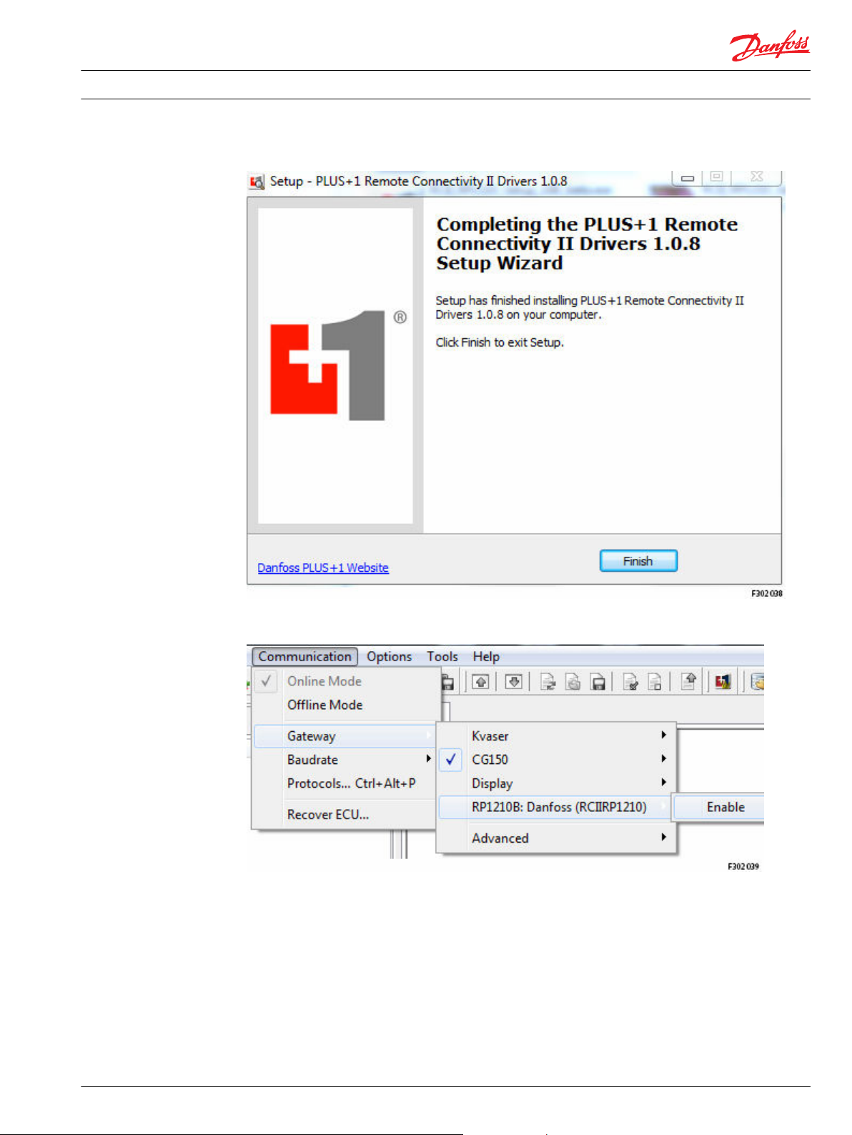
Click to next and the installation start.
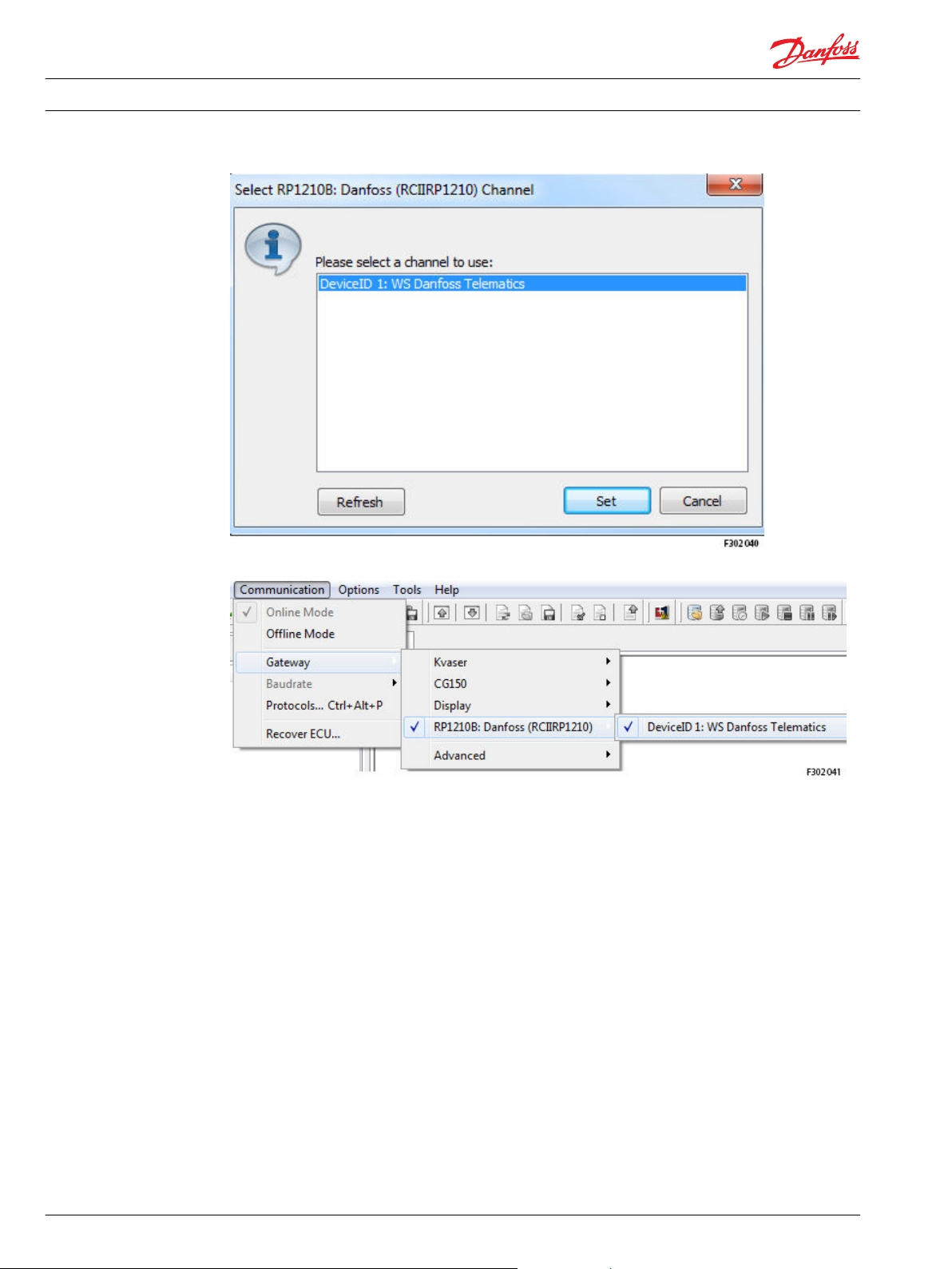
After the installation of the driver, start the Service Tool program and in the main window select the
menu Communication > Gateway> and enable the new gateway RP1210B: Danfoss (RCIIRP1210).
Select the available channel:
L1419125 • Rev BC • January 2015 55
Page 56
Installation Guide
WS 403 Remote Solution
PLUS+1® Service Tool: connect to a remote device
After the channel selection the gateway list show the following information:
After the activation [enable] of this driver a PLUS+1® Remote Connection Log-in Dialog window will pop
up:
56 L1419125 • Rev BC • January 2015
Page 57

Installation Guide
WS 403 Remote Solution
PLUS+1® Service Tool: connect to a remote device
Danfoss Telematics login
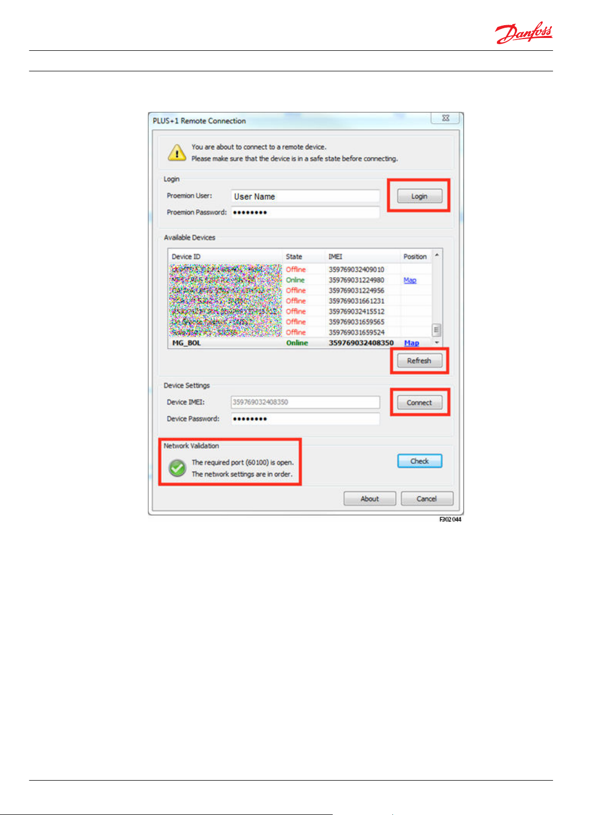
When logged in, the available machines will be listed here. In the Danfoss Telematics Login section use
the Web Portal credential to connect to the Danfoss server and populate the Machines Overview section
with all the machines available with details (Name, State, IMEI and Position). The settings (Danfoss
Telematics Login User/ Password, Device IMEI/Password) will automatically be saved when closing the
dialog, and restored the next session.
Press the About button to see version information about the Remote Gateway. Press the Cancel button to
close the Remote Gateway (to select a different gateway, for example). If the login dialog is closed, reset
the gateway to be able to login again.
L1419125 • Rev BC • January 2015 57
Page 58

Installation Guide
WS 403 Remote Solution
PLUS+1® Service Tool: connect to a remote device
Name
Is the Name of the Machine.
Press the Refresh button the get the latest status for the devices.
State
Represent the connection availability of the machine.
Online
Offline
Busy
It is possible to Real Time connect to a machine that is online.
The machine if offline. It is not possible to Real Time connect to a machine in this state.
The device is busy. A user is currently Real Time connected to the machine. It is not possible to
connect to a machine in this state.
IMEI
The International Mobile Station Equipment Identity or IMEI is a number, usually unique, to identify 3GPP
(i.e., GSM, UMTS) and mobile phones, as well as some satellite phones. It is usually found printed inside
the battery compartment of the phone, but can also be displayed on-screen on most phones by entering
*#06# on the dial pad, or alongside other system information in the settings menu on smartphone
operating systems.
The IMEI number is used by a GSM network to identify valid devices and therefore can be used for
stopping a stolen phone from accessing that network. For example, if a mobile phone is stolen, the
owner can call his or her network provider and instruct them to "blacklist" the phone using its IMEI
number. This renders the phone useless on that network and sometimes other networks too, whether or
not the phone's SIM is changed.
The IMEI is only used for identifying the device and has no permanent or semi-permanent relation to the
subscriber. Instead, the subscriber is identified by transmission of an IMSI number, which is stored on a
SIM card that can (in theory) be transferred to any handset. However, many network and security features
are enabled by knowing the current device being used by a subscriber.
Position
Click the Map link to show the machine location directly in the predefined Web Browser.
58 L1419125 • Rev BC • January 2015
Page 59

Installation Guide WS 403 Remote Solution
PLUS+1® Service Tool: connect to a remote device
Machine settings
1. Select a machine in the Machine List to automatically set the machine IMEI, and enter the correct
password.
2. Press the Connect button to connect to the selected machine.
3. The Connect button will be disabled until you are logged on and also until an online machine is
selected.
Network validation
Press the Check button to evaluate the network connection. Your Internet connection must allow traffic
for port 443 and 60100 to be able to login and connect to a device.
If the status check fails, some or both ports (443 & 60100) are most likely blocked by the network firewall.
Please contact your IT department for further information if you experience this error.
Network status
The required ports (443 && 60100) are open.
The network settings are in order.
The required port (443) is not open.
Check the Internet connection.
The required port (60100) is not open.
Check the Internet connection.
The required ports (443 && 60100) are not open.
Check the Internet connection.
Unable to check port status.
Connection might not be possible.
Checking necessary ports (443 && 60100)... The necessary ports are checked. Please wait for the
Network configuration not checked.
Press button to validate port status (443 & 60100).
No problems detected. Connection shall be possible.
Port 443 is not open. It will not be possible to login.
Port 60100 is not open. It will not be possible to connect
to a machine.
None of port 443 and 60100 are open. It will not be
possible to login and connect to a machine.
A problem occurred while checking the port status. The
port status is unknown.
check to finish.
Press the Check button to validate the Internet
connection.
L1419125 • Rev BC • January 2015 59
Page 60
Installation Guide
WS 403 Remote Solution
PLUS+1® Service Tool: connect to a remote device
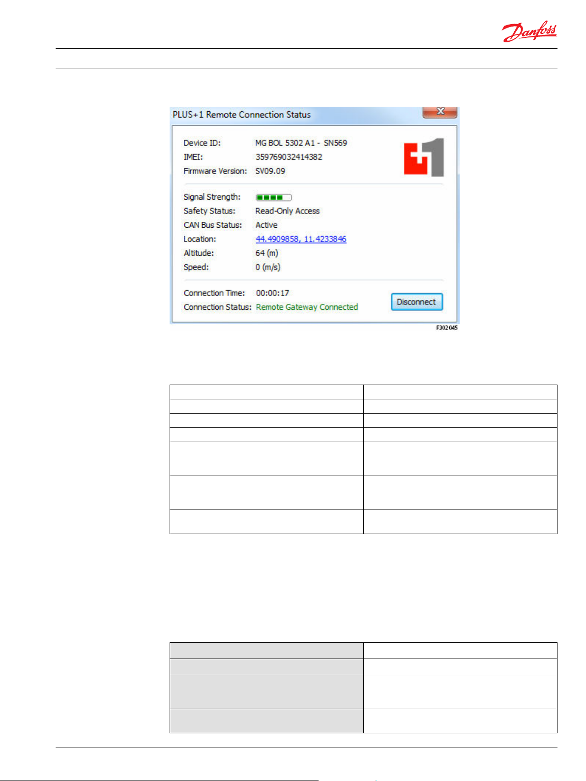
The status dialog
When connected to a device, a pop up status dialog window will show up:
60 L1419125 • Rev BC • January 2015
Page 61
Installation Guide WS 403 Remote Solution
PLUS+1® Service Tool: connect to a remote device
Device information
Information about the currently connected device
Device ID The device ID.
IMEI The device IMEI.
Firmware Version The device firmware version.
Signal Strength The signal strength for the device (0-5).
Safety Status Read-Only Access: Not possible to download parameter
values and applications. Write Access: Possible to
download parameter values and applications.
CAN bus Status Active: The device is on bus and messages are available
Inactive: The device is off bus. No ECU connection will be
available.
Location The location of the device. Click the link to show the
device location.
Connection information
Information about the current connection.
Press the Disconnect button to disconnect from the device. The connection will be closed and the login
dialog will be displayed again.
Connection status
Remote Gateway Connected
Remote Gateway Disconnected
Disconnecting. Please wait...
Connection lost. Please wait...
L1419125 • Rev BC • January 2015 61
The connection is up and running.
Disconnected from the device.
The disconnection procedure is running. Please wait for
the connection to close. The login dialog will be shown
when the disconnection is complete.
The connection to the device is lost. Please wait for the
login dialog to reconnect, if desirable.
Page 62

Installation Guide WS 403 Remote Solution
PLUS+1® Service Tool: connect to a remote device
An icon is also available in the status bar.
Double-click this icon to toggle between a visible/hidden dialog. Right-click the icon for more options:
Show Status
Hide Status
Disconnect
Exit
Show the status dialog (the status dialog is currently hidden).
Hide the status dialog (the status dialog is currently visible).
Close the current connection.
Close the status dialog.
Danfoss Telematics and PLUS+1® Service Tool troubleshooting
Logging in
Possible errors when logging in
Symptom Reason Error code
Not possible to login Could not connect to server 12
Connecting to device
Possible errors when connecting to a device
Symptom Reason
Not possible to connect Device Password is invalid 22
Incorrect username or password 20, 21
Device password request
time out
Device information request
timed out
Solution
Most likely because device
is offline
Check network connection
Error code
24
23, 25, 26
62 L1419125 • Rev BC • January 2015
Page 63

1
1
1
11
P301 771
109
107
Installation Guide WS 403 Remote Solution
Appendix A - Mounting
WS devices feature an easy-to-install enclosure which can be bolted to a panel or mounted to a DIN rail
TS35.
The figures and tables below show the required mounting accessories and relevant dimensions.
Panel-mount installation
Orientations of panel-mount installation - option 1
The figures show two devices directly bolted to a panel in different orientations:
Parts required for panel-mount installation - option 1
For mounting option 1, the following parts are required:
Number in
figure
1 Hex socket head cap screw DIN 912 – M4x40 4
Description Quantity required for mounting
one device
L1419125 • Rev BC • January 2015 63
Page 64

4
P301 773
Installation Guide
Appendix A - Mounting
WS 403 Remote Solution
Orientations of panel-mount installation - option 2
DIN rail installation
Parts required for panel-mount installation - option 1
For mounting option 2, the following parts are required:
Number in
figure
2 Washer DIN 125, ø 5.3 mm 2
3 Hex head cap screw DIN 931 – M5x25 2
Description Quantity required for mounting
Orientation of DIN rail installation
one device
64 L1419125 • Rev BC • January 2015
Page 65

Installation Guide WS 403 Remote Solution
Appendix A - Mounting
The figure shows one device mounted to a DIN rail with the help of the DIN rail mounting kit, available as
accessory.
Parts required for DIN rail installation
Number in figure Description Quantity required for mounting
4 DIN rail mounting kit for DIN rail
For a list of available accessories, see WS 403 Remote Solution Technical Information - L1426375
one device
1
mounting according to EN 50022
L1419125 • Rev BC • January 2015 65
Page 66

Installation Guide WS 403 Remote Solution
66 L1419125 • Rev BC • January 2015
Page 67

Installation Guide WS 403 Remote Solution
L1419125 • Rev BC • January 2015 67
Page 68

Danfoss
Power Solutions GmbH & Co. OHG
Krokamp 35
D-24539 Neumünster, Germany
Phone: +49 4321 871 0
Danfoss
Power Solutions ApS
Nordborgvej 81
DK-6430 Nordborg, Denmark
Phone: +45 7488 2222
Danfoss
Power Solutions (US) Company
2800 East 13th Street
Ames, IA 50010, USA
Phone: +1 515 239 6000
Danfoss
Power Solutions
(Shanghai) Co., Ltd.
Building #22, No. 1000 Jin Hai Rd
Jin Qiao, Pudong New District
Shanghai, China 201206
Phone: +86 21 3418 5200
Products we offer:
Comatrol
www.comatrol.com
Schwarzmüller-Inverter
www.schwarzmuellerinverter.com
Turolla
www.turollaocg.com
Valmova
www.valmova.com
Hydro-Gear
www.hydro-gear.com
Daikin-Sauer-Danfoss
www.daikin-sauer-danfoss.com
Bent Axis Motors
•
Closed Circuit Axial Piston
•
Pumps and Motors
Displays
•
Electrohydraulic Power
•
Steering
Electrohydraulics
•
Hydraulic Power Steering
•
Integrated Systems
•
Joysticks and Control
•
Handles
Microcontrollers and
•
Software
Open Circuit Axial Piston
•
Pumps
Orbital Motors
•
PLUS+1® GUIDE
•
Proportional Valves
•
Sensors
•
Steering
•
Transit Mixer Drives
•
Danfoss Power Solutions is a global manufacturer and supplier of high-quality hydraulic and
electronic components. We specialize in providing state-of-the-art technology and solutions
that excel in the harsh operating conditions of the mobile off-highway market. Building on
our extensive applications expertise, we work closely with our customers to ensure
exceptional performance for a broad range of off-highway vehicles.
We help OEMs around the world speed up system development, reduce costs and bring
vehicles to market faster.
Danfoss – Your Strongest Partner in Mobile Hydraulics.
Go to www.powersolutions.danfoss.com for further product information.
Wherever off-highway vehicles are at work, so is Danfoss. We offer expert worldwide support
for our customers, ensuring the best possible solutions for outstanding performance. And
with an extensive network of Global Service Partners, we also provide comprehensive global
service for all of our components.
Please contact the Danfoss Power Solution representative nearest you.
Danfoss can accept no responsibility for possible errors in catalogues, brochures and other printed material. Danfoss reserves the right to alter its products without notice. This also applies to
products already on order provided that such alterations can be made without changes being necessary in specifications already agreed.
All trademarks in this material are property of the respective companies. Danfoss and the Danfoss logotype are trademarks of Danfoss A/S. All rights reserved.
L1419125 • Rev BC • January 2015 www.danfoss.com
Local address:
©
Danfoss A/S, 2015
 Loading...