

Page 1

User Manual
Danfoss Telematics Solutions
WS103 Remote Solution
powersolutions.danfoss.com
Page 2

Revision history Table of revisions
Date Changed Rev
July 2016 First edition 0101
User Manual
WS103 Remote Solution
2 | © Danfoss | July 2016 AN00000339en-US0101
Page 3

About this manual
User Manual........................................................................................................................................................................................5
Overview
WS103 remote solution..................................................................................................................................................................6
OEM responsibility........................................................................................................................................................................... 6
Safety critical functions.................................................................................................................................................................. 7
FCC notice........................................................................................................................................................................................... 8
Device elements and functions
WS103 device elements.................................................................................................................................................................9
WS103 nameplate label................................................................................................................................................................. 9
System configuration
WS103 set up requirements.......................................................................................................................................................10
WS103 kit.......................................................................................................................................................................................... 10
Wiring.................................................................................................................................................................................................10
Connectors....................................................................................................................................................................................... 10
CAN / Power connector..........................................................................................................................................................11
RS-232 connector..................................................................................................................................................................... 11
Main connector......................................................................................................................................................................... 11
Configuration connector....................................................................................................................................................... 12
Connect USB/RS232 converter cable.................................................................................................................................12
CAN bus termination......................................................................................................................................................... 12
Connect power supply......................................................................................................................................................12
Indicator element...........................................................................................................................................................................13
WS System Tools
Tools included.................................................................................................................................................................................14
WS Wireless configurator
Install WS wireless configurator................................................................................................................................................15
Verify version...................................................................................................................................................................................17
Set COM port assigned to the USB-RS232 converter cable............................................................................................ 17
Create new configuration...........................................................................................................................................................18
Device configuration.................................................................................................................................................................... 19
CAN Receive configuration.........................................................................................................................................................21
WLAN configuration..................................................................................................................................................................... 22
Bluetooth® configuration............................................................................................................................................................ 26
Pair the WS103 to laptop.............................................................................................................................................................27
Expert configuration.....................................................................................................................................................................29
Safety configuration......................................................................................................................................................................31
Save configuration.........................................................................................................................................................................33
Load configuration........................................................................................................................................................................34
Exit.......................................................................................................................................................................................................34
Connect, Disconnect, Read and Write data to WS103......................................................................................................34
Device information.................................................................................................................................................................. 36
WS103 connected to WS Wireless Configurator
Select the COM port assigned to the USB/RS232 converter cable...............................................................................37
Locate assigned COM port....................................................................................................................................................37
Latency timer............................................................................................................................................................................. 38
Connection..................................................................................................................................................................................38
WS103 general settings
Set node ID and CAN bus Baudrate.........................................................................................................................................39
CAN receive......................................................................................................................................................................................39
Expert................................................................................................................................................................................................. 40
Safety..................................................................................................................................................................................................40
WS103 connected to Wi-Fi infrastructure
Establish a hot-spot connection with the configured WS103....................................................................................... 41
User Manual
WS103 Remote Solution
Contents
©
Danfoss | July 2016 AN00000339en-US0101 | 3
Page 4

WS103 connected to Bluetooth
®
Establish a Bluetooth® connection with configured WS103...........................................................................................43
WS103 bridging settings
Establish a WLAN automatic connection with the configured WS103.......................................................................46
Establish a Bluetooth® automatic connection with the configured WS103............................................................. 46
PLUS+1® Service Tool connected to a WS103
Install WS Wireless driver.............................................................................................................................................................48
WS103 Connection Manager.....................................................................................................................................................50
Add WLAN Infrastructure connection.................................................................................................................................... 51
If error is indicated....................................................................................................................................................................53
Add Bluetooth® connection........................................................................................................................................................54
If error is indicated....................................................................................................................................................................56
WS Wireless Driver version......................................................................................................................................................... 56
Appendix A – Dimensions
WS103 dimensions........................................................................................................................................................................ 57
WS103 connectors and indicator element........................................................................................................................... 57
Appendix B – Mounting
Direct screw install.........................................................................................................................................................................58
Ingress protection rating.............................................................................................................................................................58
User Manual
WS103 Remote Solution
Contents
4 | © Danfoss | July 2016 AN00000339en-US0101
Page 5

User Manual
This user manuals includes:
•
Screen captures of software windows and menus
•
Tables that describe window elements and menu commands
•
Examples and step-by-step instructions where required
This document is intended for qualified technicians and electricians with advanced knowledge in
electrical engineering and CAN Bus systems. Their knowledge must be sufficient to estimate the risks and
hazards of operating the device before designing, modifying, servicing the control system, and/or
integrating it into systems with components of other manufacturers.
User Manual
WS103 Remote Solution
About this manual
©
Danfoss | July 2016 AN00000339en-US0101 | 5
Page 6

WS103 remote solution
The WS103 interface is designed to provide wireless access to the CAN data of a vehicle, machine, or
system via WLAN / Bluetooth®.
The WS103 is a stand-alone multiradio module which includes Wi-Fi, Classic Bluetooth® and Bluetooth
®
Low Energy (planned). The Wi-Fi support conforms to IEEE 802.11a/b/g/n, and has support for dual-band
2.4 GHz and 5 GHz operation.
The module can be used as CAN-WLAN / Bluetooth® interface or wireless CAN-CAN bridge. In a CAN-
WLAN / Bluetooth® interface, the module is used for transmission of CAN data to other WLAN /
Bluetooth® / network devices, such as computers, smartphones, or tablets on which the CAN data can be
managed and evaluated. The data exchange is bidirectional when the device is configured as a WLAN /
Bluetooth® interface via software.
In a wireless CAN-CAN bridge, CAN data is transmitted wireless between two WS103 modules. The CANCAN bridge serves as a replacement for a CAN cable for more efficient and dependable communication
of operational data over long runs and moving joints.
The interface is suitable for use in mobile and stationary systems for industrial, agricultural, and forestry
machinery.
The WS103 is an Easy-to-Install plastic enclosure which can be bolted to a panel.
OEM responsibility
The OEM of a machine or vehicle in which Danfoss products are installed has the full responsibility for all
consequences that might occur. Danfoss has no responsibility for any consequences, direct or indirect,
caused by failures or malfunctions.
•
Danfoss has no responsibility for any accidents caused by incorrectly mounted or maintained
equipment.
•
Danfoss does not assume any responsibility for Danfoss products being incorrectly applied or the
system being programmed in a manner that jeopardizes safety.
•
All safety critical systems shall include an emergency stop to switch off the main supply voltage for
the outputs of the electronic control system. All safety critical components shall be installed in such a
way that the main supply voltage can be switched off at any time. The emergency stop must be easily
accessible to the operator.
User Manual
WS103 Remote Solution
Overview
6 | © Danfoss | July 2016 AN00000339en-US0101
Page 7

Safety critical functions
Before deploying the device described in this document, read the entire manual including all safety
information.
Non-observance of this document, operation that is not in accordance with use as prescribed, wrong
installation or tampering of device can be harmful to people and the environment.
Keep this manual for future use and make all information available to anyone deploying the device, even
after installation.
In the event of malfunctions or uncertainties, please contact the manufacturer.
•
Do not apply this device in machines and/or applications where life depends on the proper (fault
free) operation of the device.
•
Do not enable function until sufficient wireless network availability (WLAN / Bluetooth®) is ensured,
failures or malfunctions of the device can lead to erroneous data transmission.
•
Never rely solely on wireless device for essential communications because data transmission at all
times and under all conditions cannot be guaranteed.
•
Do not use this device in safety-related applications, this device operates using radio signals, and is
not approved for use in safety-related applications.
•
Do not operate this device until systems are checked for conformity with legal requirements.
•
The device must only be put into operation by qualified technicians and electricians with advanced
knowledge of electrical engineering and fieldbus systems.
•
The integrator of this device is responsible to check and comply with regional directives and
requirements.
•
The device does not comply to the directive 94/9/EC and must therefore not be used in hazardous
areas.
User Manual
WS103 Remote Solution
Overview
©
Danfoss | July 2016 AN00000339en-US0101 | 7
Page 8

FCC notice
The device(s) described in this manual may only be used in mobile or stationary systems in which under
normal operating conditions the separation distance between the antenna(s) and all persons is at least 20
cm (8 in). The antenna(s) (internal or external) must further not be co-located or operated in conjunction
with any antenna or transmitter. Compliance of WS unit devices in all final product configurations is the
responsibility of the integrator.
This equipment has been tested and found to comply with Part 15 of the FCC Rules with the limits for a
digital instrument of class B. These limits are designed to provide reasonable protection against harmful
interference in a residential installation. This equipment generates, uses, and can radiate radio frequency
energy and, if not installed and used in accordance with the instructions, may cause harmful interference
to radio communications. However, there is no guarantee that interference will not occur in a particular
installation. If this equipment does cause harmful interference to radio or television reception, which can
be determined by turning the equipment off and on, the user is encouraged to try to correct the
interference by one or more of the following measures:
•
Reorient or relocate the receiving antenna.
•
Increase the separation between the equipment and receiver.
•
Connect the equipment into an outlet on a circuit different from that to which the receiver is
connected.
•
Consult the dealer or an experienced radio / TV technician for help.
Loss of FCC certification possible:
•
Only use antennas that are suitable for the frequency range used so that the device does not lose its
wireless qualification; only approved antennas may be used.
•
It is the responsibility of the customer to ensure that the external antenna used does not remove the
wireless qualification.
•
Keep the end of the antenna away from metal components to avoid interference.
Modifications not expressly approved by the manufacturer could void the user's authority to operate the
equipment under FCC rules.
User Manual
WS103 Remote Solution
Overview
8 | © Danfoss | July 2016 AN00000339en-US0101
Page 9

This following gives an overview of the device elements and functions and also describes the intended
use. Refer to WS103 Remote Solution Technical Information, BC00000365 for lists of available device
variants and the product certifications.
WS103 device elements
WS103 Remote Solutions device elements
1
2
3
4
5
6
7
kwa1459357672625
1. Plastic housing 5. RS-232 connector (configuration and FW update)
2. Mounting holes 6. Front label
3. Name plate, located on the side of the housing 7. CAN/power/status LED
4. Main connector (CANbus / power supply / clamp 15)
WS103 nameplate label
WS103 nameplate label, located on the side of the housing
User Manual
WS103 Remote Solution
Device elements and functions
©
Danfoss | July 2016 AN00000339en-US0101 | 9
Page 10

The WS Remote Solutions is a family of telematics devices.
WS103 set up requirements
WS Wireless Configurator (version 2.0.0 or above) installed on PC/Laptop, USB/RS232 converter cable
(part number 11165987), and an external power supply are required to set up the WS103 unit.
System configuration schematic
2
1
3
4
kwa1466185098236
1.
USB/RS232 Converter cable (part number 11165987)
2. Clamp 15 (optional)
3. Can Bus network
4. External power supply
WS103 kit
WS103 kit (Part number: 11168245) components
Device Description Part number
WS103 kit CONTROL, WS103 Wireless 11165988
CAN Cable M12 5-pin /open 5m 11149645
Protection Cap M12 Flange Plug 11169389
Wiring
When installing control system hardware, one of the most important things to consider is the type of
cable to be used for connecting together each component of the system.
C
Caution
Using incompatible accessories may damage your equipment. Incorrect selection or wiring of such cables
can cause a wide range of problems, including erratic or non-existent communication, an increased
danger of component damage due to freak voltages, or an increased chance of EMI (Electro Magnetic
Interference), all of which can have an adverse effect on the installation. If you are using other accessories
than those contained in the WS103 Kit, make sure that they are compatible with the devices.
Connectors
WS103 is equipped with the following connectors:
•
One main connector (CAN/Power, J-1)
•
One configuration connector (RS-232, J-2)
The antenna is integrated into the device housing, below the pin assignment of the two 5-pin M12
connectors.
User Manual
WS103 Remote Solution
System configuration
10 | © Danfoss | July 2016 AN00000339en-US0101
Page 11

CAN / Power connector
5-pin M12, male, A-coded, front view
5
21
4
3
kwa1459396274675
Connect the device to the CANbus and the power to supply voltage (DC battery or instrumental power
supply).
CAN connector J-1 (left side—top view)
Pin Designation Color Description
1 Ground Brown Power supply
2 8 to 32 VDC White Power supply
3
*
Terminal 15 Blue Ignition
4 CAN high Black CANbus
5 CAN low Gray CANbus
*
Pin 3, Terminal 15, if not used for controlling the power management, must be connected to VCC.
RS-232 connector
5-pin M12, male, A-coded, front view
5
21
4
3
kwa1459396274675
Connect the device to the PC via the RS-232 port.
RS-232 connector J-2 (right side—top view)
Pin Designation Color Description
1 Ground Brown Power supply
2 — White —
3 BOOT (DSR) Blue Boot pin, RS-232 Data Set Ready (input)
*
4 RXD RS-232h Black Receive (input)
5 TXD RS-232 Gray/Green Transmit (output)
*
PIN3 is used only to activate the boot mode. To activate the boot mode PIN3 is connected to the DTR pin of the
RS-232 interface of the PC. The software controls this signal automatically. In normal operation, this pin must not be
connected.
Main connector
The main connector serves for:
•
Connecting the WS device with power supply.
•
Connecting the WS device to the CAN Bus Network in order to operate with machine data.
‒
The signals on the CAN connection terminals CAN-Low and CAN-High must match the signals on
the CAN terminals of the connected devices.
•
Clamp15 used in the WS103 power management functionality.
User Manual
WS103 Remote Solution
System configuration
©
Danfoss | July 2016 AN00000339en-US0101 | 11
Page 12

Configuration connector
WS103 uses a RS232 port in order to be configured.
The USB/RS232 converter cable will be used together with a WS Wireless Configurator tool.
Connect USB/RS232 converter cable
Prepare communication between the PC/laptop and the USB/RS232 converter cable to allow the
configuration of the WS103 before connecting USB/RS232 converter cable to PC/laptop:
1. Go to http://www.ftdichip.com/Drivers/VCP.htm and download and install the latest VCP drivers (up
to version 2.12.10).
2. Connect RS232/USB converter cable.
Before opening the WS Wireless Configurator verify if the FTDI driver is correctly installed (check Version
in Device Manager) and make sure the RS232/USB converter cable is connected.
CAN bus termination
In each CAN bus system, signal reflections at the end of a wire or cable can cause interference, which is
one reason for transmission errors.
To minimize these reflections a terminator is placed at each end of a transmission line. This terminator
has to match the characteristic impedance of the transmission line.
In CAN bus networks, normally unshielded twisted pair cables are used for signal transmission. These
cables have a characteristic impedance of approximately 120 Ohms. Thus a resistor of 120 Ohms has to
be placed at each end of the CAN bus line between CAN-High and CAN-Low to reduce the reflections and
enable correct communication.
Connect power supply
1. Connect the power supply to the WS device. For the power connector assignment, refer to CAN /
Power connector on page 11 and RS-232 connector on page 11.
2. Connect the power supply to an electrical outlet.
User Manual
WS103 Remote Solution
System configuration
12 | © Danfoss | July 2016 AN00000339en-US0101
Page 13

Indicator element
The device is equipped with the following indicator elements: CAN / Power / STATUS multicolor LED.
If green and red colors are simultaneously on, the LED will appear orange. The following table describes
the LED light characteristics and the corresponding device status.
Power / CAN / Status LED
LED Color Light characteristics Description
Power / CAN / Status Green
Off
—
Constantly on
WLAN connection and / or Bluetooth
®
connection active
Single flash
The device is in pairing mode when
Bluetooth® Security ‘Just Works’ green
flashing (200 ms on, 1000 ms off).
Double flash
Initializing status (200 ms on, 200 ms off,
200 ms on, 200 ms off, 1000 ms off).
Triple flash
Reset status (200 ms on, 200 ms off, 200
ms on, 200 ms off, 200 ms on, 200 ms
off, 1000 ms off).
Flashing
The machine is ready to connect (200
ms on, 200 ms off).
Red
Off
There are no CAN data sent or received.
Constantly on
CAN error (such as, bus off), Error
voltage critical.
Orange
Flashing irregularly
CAN data are transmitted and received.
Appears only when green is constantly
on. The LED then flash orange.
Constantly on
Configuration Mode, Firmware Update
mode.
User Manual
WS103 Remote Solution
System configuration
©
Danfoss | July 2016 AN00000339en-US0101 | 13
Page 14

Tools included
WS System Tools is a group of tools that can be used to configure and upgrade the FW of the WS devices
and include:
•
WS configurator (to be used with WS403x and WS503x)
•
WS FW programmer (to be used with WS403x, WS503x and WS103)
•
WS wireless configurator (to be used with WS103)
The WS System Tools can be download directly from the Telematics section online at http://
powersolutions.danfoss.com/solutions/danfoss-telematics-solutions/.
User Manual
WS103 Remote Solution
WS System Tools
14 | © Danfoss | July 2016 AN00000339en-US0101
Page 15

Install WS wireless configurator
Select the setup language, by default English is selected.
Select setup language
Execute the installation of the WS Wireless Configurator program (v2.0.0 or above) on your PC/Laptop.
1. Follow the instruction shown in the Configurator Setup Wizard.
2. Select installation destination folder.
By default it is: C:\Program Files (x86)\Danfoss\WS Wireless Configurator.
3. Optional: Create start menu folder where Setup will place the program's shortcuts.
Browse defaults to Danfoss\WS System Tools.
a) Click Next.
User Manual
WS103 Remote Solution
WS Wireless configurator
©
Danfoss | July 2016 AN00000339en-US0101 | 15
Page 16
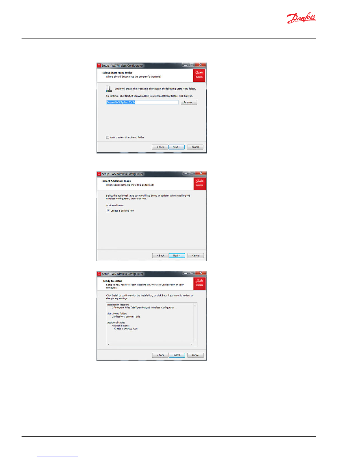
4. Optional: Select Create a desktop icon.
a) Click Next.
5. Click Install to continue with the installation.
6. Select Launch WS Wireless Configurator.
a) Click on Finish
User Manual
WS103 Remote Solution
WS Wireless configurator
16 | © Danfoss | July 2016 AN00000339en-US0101
Page 17

The WS Wireless Configurator has been installed successfully.
Verify version
1. In open program, click on Help > About WS Wireless Configurator.
2. Verify the version of the tool.
Set COM port assigned to the USB-RS232 converter cable
1. In the WS Wireless Configurator main window, either:
•
Select Options > Connection settings.
•
Click on Serial located in the lower-right corner of the configurator interface window.
User Manual
WS103 Remote Solution
WS Wireless configurator
©
Danfoss | July 2016 AN00000339en-US0101 | 17
Page 18

The Connection Settings window will appear.
2. Set the correct COM port assigned to the USB/RS232 cable converter in the Connection Settings
window. Press close.
Double check the COM port assigned to the USB-RS232 converter by verifying in Device Manager >
Ports section the USB Serial Port properties.
Example of USB Serial Port properties
Create new configuration
To create a new configuration either:
•
Go to File > New configuration.
•
Click on the New configuration icon .
The new WS103 configuration parameters are included on the following 6 tabs:
•
Device
•
CAN Receive
•
WLAN
•
Bluetooth
®
•
Expert
•
Safety
User Manual
WS103 Remote Solution
WS Wireless configurator
18 | © Danfoss | July 2016 AN00000339en-US0101
Page 19

Device configuration
CAN Baudrate
The CAN Baud-rate refers to the rate (speed) at which data is transmitted on the network. This is typically
expressed in kilobits-per-second (kbit/s) Selecting the incorrect Baud-rate can cause erratic behavior on
the network, by default it is set to 250 Kbit/s (J1939 standard).
CAN Baud-rate selection
Feedback Mode
The Feedback Mode enables the successfully transmitted CAN Messages to be sent back to the host in
order of transmission. The Feedback Mode by default is not checked. Error status and feedback output
with timestamp are available only if Feedback Mode is checked with Timestamp Mode not Off, this
allows the transmission of error status and feedback output with timestamp.
User Manual
WS103 Remote Solution
WS Wireless configurator
©
Danfoss | July 2016 AN00000339en-US0101 | 19
Page 20

Feedback Mode selections
Timestamp Mode
When Timestamp Mode is selected, a 32-bit counter value (100 microsecond resolution) is inserted after
the last data byte. The difference between absolute and relative modes is that the counter value is reset
with each received message byte in relative mode. The Timestamp Mode by default is set to Off.
Timestamp Mode settings
CANopen
WS103 is a CANopen device
CANopen node ID
It’s a 11-bit ID communication object identifier, be sure to set an ID value that is not already used by other
devices connected on CAN Bus network.
Heartbeat time [ms]
With node monitoring according to the heartbeat principle, a node automatically transmits its
communication state at regular intervals as evidence of its communication ability. The interval between
two heartbeat messages (heartbeat time) of a so-called heartbeat producer is configured by this
parameter.
By default a value of 0 (off) disables the heartbeat mechanism.
Keep the CANopen stack active while connected
By default a value of 0 (off) disables the heartbeat mechanism. Selecting Keep the CANopen stack
active while connected, WS103 can receive or transmit CAN open messages to the following IDs:
•
Receive: 0x000, 0x621
User Manual
WS103 Remote Solution
WS Wireless configurator
20 | © Danfoss | July 2016 AN00000339en-US0101
Page 21

•
Transmit: 0x5A1, 0x721
By default, Keep the CANopen stack active while connected is not checked.
Selecting parameter Enable boot-up message enables WS103 to send a CAN message at every boot-up,
by default it is not checked.
Enable boot-up message
This parameter enables WS103 to send a CAN message at every boot-up, by default it is not checked.
CAN Receive configuration
It is possible to define the CAN message received by WS103.
Display Format
The values of Mask and CAN Identifier can be shown in decimal or hexadecimal format. By default it is
set to hexadecimal.
CAN ID Format
Set the input format for CAN receive objects. J1939 option can provide a more convenient way to
configure CAN received object using PGN values. By default CAN ID Format is set to Layer 2.
WS103 doesn’t support J1939 transport protocol.
User Manual
WS103 Remote Solution
WS Wireless configurator
©
Danfoss | July 2016 AN00000339en-US0101 | 21
Page 22

By default two objects are defined as active.
All CAN Messages with ID Length 11-bit and 29-bit without Mask and with Downsampling at 0 ms are
received and managed by WS103.
WLAN configuration
WLAN settings
Operating mode
•
In the Infrastructure Operating Mode, the WS103 communicates via a central access point. Most
access points include a DHCP server and device IP settings. These are automatically assigned (if DHCP
mode on WS103 is set to client).
•
In the Mini Access Point (MiniAP) Operating Mode, the device acts as an access point for a limited
number of clients. If the DHCP mode is set to server, WS103 will assign IP addresses to client devices
based on the configured settings.
SSID
Select your wireless network Service Set Identifier (SSID). In Infrastructure Operating Mode, the SSID must
be equivalent to the wireless network name generated by the local access point. In MiniAP Operating
Mode, the name of the wireless network will be generated by WS103.
BSSID
The BSSID is the MAC address of the access point and must be entered in the form: 11:22:33:44:55:66. By
default this field is empty, if it remains empty the device will use the SSID to connect to the Network.
Authentication type
Choices for type of wireless security are:
User Manual
WS103 Remote Solution
WS Wireless configurator
22 | © Danfoss | July 2016 AN00000339en-US0101
Page 23
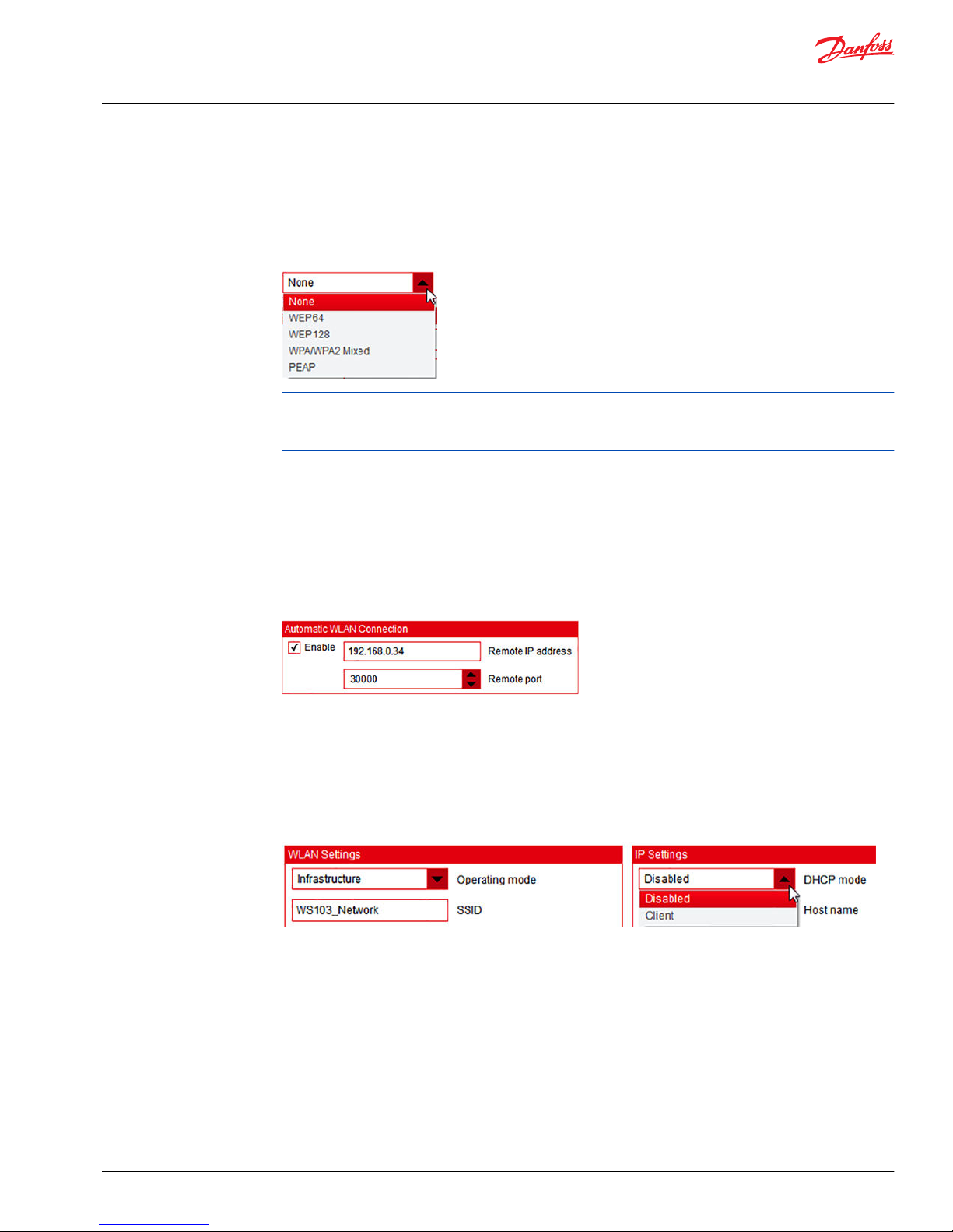
•
WEP64: 10 hexadecimal digits
•
WEP128: 26 hexadecimal digits
•
WPA WPA2 Mixed: 8 to 63 alphanumeric digits
•
PEAP: 0 to 64 printable ASCII characters (requires also user name, domain name, and password)
For networks that do not have a wireless security password select None.
If the WS103 FW version is below 1.0.0 the MiniAP cannot generate a secure wireless network. With the
WS103 FW version 1.0.0 the MiniAP is temporarily not available and will be introduced in the WS103 FW
2.0.0 with the secure wireless network.
Authentication Key
In Infrastructure Operating Mode, the password is required to access to the wireless network. In the
MiniAP Operating Mode the password is needed to access the wireless network generated by WS103.
Automatic WLAN Connection
WS103 is able to establish a TCP/UDP connection to another device automatically. When this option is
enabled, the remote IP address and remote port of the other device can be defined . This option is
required when operating two WS103 devices in bridging mode.
IP Settings
DHCP mode
If operating mode is set to infrastructure the DHCP mode can be either:
•
Disabled
•
Client
If DHCP mode is Disabled, the configured static address information is used.
User Manual
WS103 Remote Solution
WS Wireless configurator
©
Danfoss | July 2016 AN00000339en-US0101 | 23
Page 24

If DHCP mode is Client, the address information is derived from a DHCP server in the network. All fields
that are not relevant will be grayed out (disabled). Recommended operating mode is Infrastructure.
If operating mode is MiniAP then DHCP mode can be either:
•
Disabled
•
Server
If DHCP mode is Server (MiniAP only) the static address information is used and WS103 constitutes a
DHCP server. This server then assigns address information to DHCP clients based on the configured static
information.
User Manual
WS103 Remote Solution
WS Wireless configurator
24 | © Danfoss | July 2016 AN00000339en-US0101
Page 25

If DHCP mode is Disabled, only the configured static address information is used for all devices connected
on WS103_Network wireless network.
Hostname
Hostname is a simple name for the device in a network. It is not the name for the network (see SSID in
WLAN settings on page 22), instead it is the name for the device. For example, this name is displayed in
the WLAN device list of the application that could be developed for smart devices.
IP address
This is the static IP address of WS103. This setting is used if DHCP mode is disabled or DHCP is in server
mode.
Port number
This is the local port opened for communication.
Network mask
This is the static Network mask for determining the local subnet. This setting is used if DHCP mode is
disabled or DHCP is in server mode.
Gateway address
The gateway address is necessary to address another device outside of the device’s subnet. It is typically
the IP address of the access point in infrastructure mode. This setting is used if DHCP mode is disabled or
DHCP is in server mode.
DNS server
This is the IP address of the DNS server, which is required when addressing remote devices by host name
instead of IP address.
The WS103 does not have an internal DNS server, so an external DNS server is needed for host name
addressing.
This setting is used if DHCP mode is disabled or DHCP is in server mode.
User Manual
WS103 Remote Solution
WS Wireless configurator
©
Danfoss | July 2016 AN00000339en-US0101 | 25
Page 26

Bluetooth® configuration
Device Configuration
Enable
Check Enable to enable the WS103 Bluetooth® Classic functionality.
Device name
This is the identification name (simple name, example WS103 SNnn) of the Bluetooth® device, and will
show in the list of Bluetooth® devices during the pairing process with a laptop.
Discoverable
If Discoverable is checked, the device is visible and can be found during an inquiry scan. PairableIf
Pairable is checked it will be activated, and the device can be paired with another Bluetooth® device.
Security Settings
Security mode Bluetooth® 2.0
The security modes available for the Bluetooth® connection are:
•
Disabled (default setting)
•
Just Works (used if device has no input and no output capabilities)
Allow Bluetooth® 2.0 pairing
Check this functionality if you are using a Bluetooth® 2.0 device that requires a pin code for the pairing,
(by default it is checked).
Pin code
User Manual
WS103 Remote Solution
WS Wireless configurator
26 | © Danfoss | July 2016 AN00000339en-US0101
Page 27

This code is applied for pairing a Bluetooth® device 2.0 (if Allow Bluetooth® 2.0 pairing variable is not
checked the pin code is not necessary). By default the Pin code is set to: 0000.
SPP Server
Enable
If checked the Bluetooth® SPP service (a simple client-server connection process) is available, (by default it
is checked).
Service name
This is a simple name to represent the Bluetooth® service.
Automatic Bluetooth®Connection
This functionality is used to establish automatically a Bluetooth® connection with a client Bluetooth
®
device, (such as, another WS103 to establish a Bluetooth® CAN bridging functionality). When this option is
enabled you can enter a Bluetooth® MAC address or a device name. The Bluetooth® MAC address is in the
format: 11:22:33:44:55:66.
Pair the WS103 to laptop
Use these configuration settings for pairing the WS103 to laptop
1. Open the Bluetooth® Add Device on the laptop.
WS103 is listed.
User Manual
WS103 Remote Solution
WS Wireless configurator
©
Danfoss | July 2016 AN00000339en-US0101 | 27
Page 28

2. Select WS103 and click next.
The device will be installed and a specific COM port will be assigned on it.
3. Go to Devices and Printers on the laptop, click on Show Bluetooth Devices.
4. Select the WS103 and right click on Properties, then click on Services tab to see the COM port
assigned with the service: COM9.
User Manual
WS103 Remote Solution
WS Wireless configurator
28 | © Danfoss | July 2016 AN00000339en-US0101
Page 29

Expert configuration
Start-up Mode
Start CAN message output on WLAN side after link is established is selected by default. CAN
messages are then transmitted by means of WLAN while a TCP connection is established.
NMT Start-up Mode
When Enter operational mode automatically and send NMT start to all nodes is selcted a NMT start
message is sent to all CAN bus nodes (CAN open) when WS103 enters into Operational mode
(automatically at Start-up). By default, Enter operational mode automatically is selected. The device is
set to go automatically in operational mode without send the broadcast message over the network.
Performance Parameters
The following parameters value can be defined:
•
CAN receive loops per cycle
•
Wireless receive loops per cycle
Both parameters are set by default to 1024.
User Manual
WS103 Remote Solution
WS Wireless configurator
©
Danfoss | July 2016 AN00000339en-US0101 | 29
Page 30

Power Management Settings
When Enable active sleep and clamp 15 wakeup is selected the time [sec] can be set until WS103 goes
into sleep mode after clamp 15 (pin 3 in the main connector) goes to 0. By default Disabled is selected.
SDO Server Settings
Do not change the parameter values in the SDO Server Settings. Contact DTS support for more
information.
User Manual
WS103 Remote Solution
WS Wireless configurator
30 | © Danfoss | July 2016 AN00000339en-US0101
Page 31
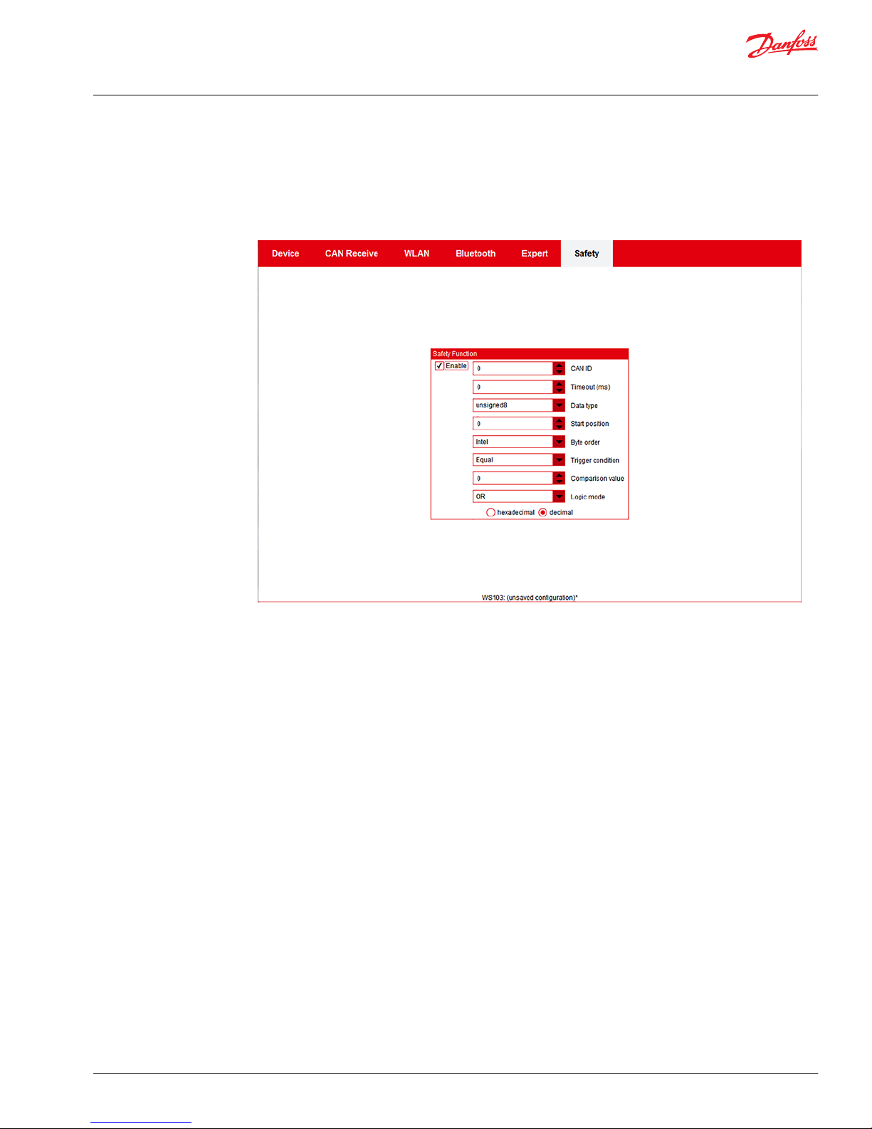
Safety configuration
If enabled, a safety mechanism can be used to not allow specific features in the PLUS+1® Service Tool
(specifically write parameters, update firmware) when the global safety mechanism state is inactive. The
global safety mechanism state is determined by comparing data from specified CAN message to a given
value using the configurable logic mode (OR/AND).
Enable
•
Not checked: Full access of read and write to the PLUS+1® application
•
Checked: Limited access to the PLUS+1® application, only read of data is allowed
See all Safety variables in order to define the global safety mechanism.
CAN ID
The global safety mechanism CAN identifier can be 11-bit or 29-bit. The type codes are:
•
Bit 29 = 0: 11-bit type
•
Bit 29 = 1: 29-bit type
•
Bits 0 to 28: CAN identifier
Timeout (ms)
The global safety mechanism Timeout configures the CAN message sent by the control system cyclically
on CAN bus. After the timeout time, if the CAN message configured is not received by the WS device, the
global safety mechanism is disabled. If this value is set to zero, the timeout control is switched off.
It is possible to change the global safety mechanism state by using a single message transmission.
Data type
The following types of information are possible to configure for the global safety mechanism state, by
default the U8 is selected.
User Manual
WS103 Remote Solution
WS Wireless configurator
©
Danfoss | July 2016 AN00000339en-US0101 | 31
Page 32

Start position
On the global safety mechanism state, the Start Position of the byte of the configured CAN Message can
be defined and have the following range of validity: 0 .. 7 (byte0..byte7), byte0 is selected by default.
Byte order
On the global safety mechanism state, the Byte Order can be defined between:
•
Intel Hex Format (Low-Byte - High-Byte) (selected by default)
•
Motorola Hex Format (High-Byte - Low Byte)
Trigger condition
Trigger condition determines how incoming data can be compared with a value. The following
conditions are possible (Equal is selected by default).
Comparison value
The value is compared with the global safety mechanism state read on CAN Bus network using the
condition selected.
If the condition is true the WS unit switches automatically from Read Only to Write Access mode. Value is
set to 0 by default.
Logic mode
Possibility to include an additional internal variable to determine the global safety mechanism state. The
variable can only be set by an external SDO request (object index 0x5040, sub-index 02, set to 0 by
default).
Logic Mode is set to OR by default. The global safety mechanism state will work as follows:
User Manual
WS103 Remote Solution
WS Wireless configurator
32 | © Danfoss | July 2016 AN00000339en-US0101
Page 33

How the global safety mechanism state works
1. State CAN
2. State Internal
3. Logic mode (AND / OR)
4. Global Safety Mechanism - State
Save configuration
1. When the configuration is finalized, save it to: File > Save configuration as….
2. Browse the right path and indicate the name (Always include a version management of configuration
by including version details). The configuration file has the extension .clk.
When a configuration is saved, the path with the name of the configuration shows on the lower part of
the WLAN Configurator user interface.
When a saved configuration is modified, the possibility to save the current modified configuration
(normally disabled after the save configuration as…) appears in the file menu. Save by either pressing the
Save configuration icon or go to File > Save configuration.
User Manual
WS103 Remote Solution
WS Wireless configurator
©
Danfoss | July 2016 AN00000339en-US0101 | 33
Page 34

Load configuration
If a configuration is available you can import it by either Pressing the Load configuration icon or go to
File > Load configuration
Warning message when an opened configuration is not saved
Exit
To exit the WS Wireless Configurator, close the user interface by selecting File > Exit
Warning message when an opened configuration is not saved
Connect, Disconnect, Read and Write data to WS103
1. Establish a connection between WS Wireless Configurator and WS103 by clicking on the Connect
icon.
Additional icons on the command bar:
Read data from the device
User Manual
WS103 Remote Solution
WS Wireless configurator
34 | © Danfoss | July 2016 AN00000339en-US0101
Page 35
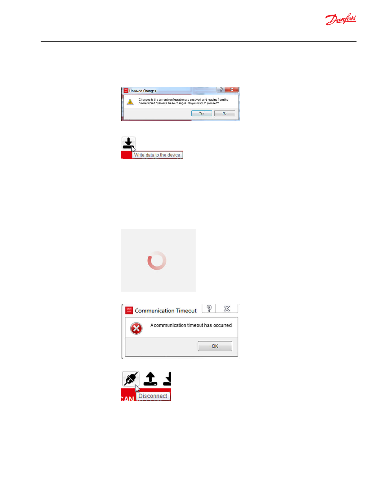
The configurator uploads all the value parameters from the WS103.
Unsaved changes warning
Write data to the device
The configurator downloads all the value parameters to the WS103.
Information about the HW connected on the configurator is in the lower part of the configurator
interface.
In case it’s necessary to update the FW, download and install the WS FW Programmer tool available
on DTS website telematics section.
If the USB/RS232 COM port is not configured correctly or in case of communication problems, the
following animated icon appears rotating in the middle of the configurator interface (meaning search
in progress).
After 15 seconds the following error message appears.
2. Press the Disconnect icon to disconnect WS103 from the WS Wireless Configurator.
When the configurator is disconnected from the device, WS103 resets and is ready.
User Manual
WS103 Remote Solution
WS Wireless configurator
©
Danfoss | July 2016 AN00000339en-US0101 | 35
Page 36
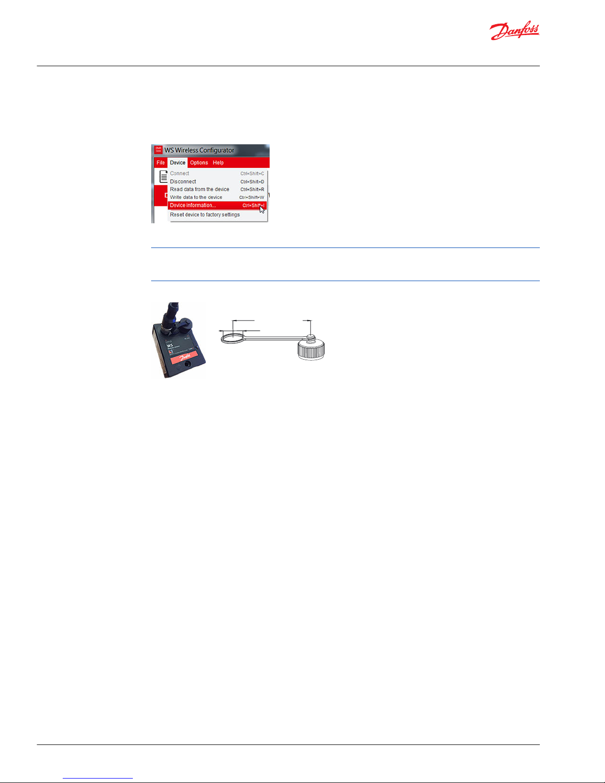
Device information
After the execution of Connection and the Read data from the device, the device information can be
seen by going to Device > Device Information command.
All the device information can be stored in the laptop memory by pressing the related Copy push button.
After the configuration of WS103, disconnect the USB/RS232 converter cable from the connector J-2.
When the device is installed on a machine, put the dust protection cap on WS103 (see WS103 kit on page
10).
WS103 dust protection cap
Ø12.50 mm [ 0.49 in]
60.00 mm [ 2.36 in]
User Manual
WS103 Remote Solution
WS Wireless configurator
36 | © Danfoss | July 2016 AN00000339en-US0101
Page 37

Select the COM port assigned to the USB/RS232 converter cable
USB-RS232 converter cable to the laptop should be correctly installed.
1. Open the WS Wireless Configurator.
2. Click on Options > Connection settings....
A connection settings window appears.
3. Select the COM port assigned to the USB/RS232 converter cable and close the window.
Locate assigned COM port
Locate the correct port assigned to the USB/RS232 converter.
1. Open the Windows® Control Panel.
2. Click on System > Device Manager > Ports
User Manual
WS103 Remote Solution
WS103 connected to WS Wireless Configurator
©
Danfoss | July 2016 AN00000339en-US0101 | 37
Page 38

The assigned COM port, for example, is indicated as USB Serial Port (COM4)
Latency timer
The latency timer (msec) is set to 1 msec by default , it is recommended to increase this value (for
example increase to 16 msec) in case of problem during the upgrade of the WS103 Firmware.
Connection
Connect icon
Device data and Connected to device is shown at bottom
User Manual
WS103 Remote Solution
WS103 connected to WS Wireless Configurator
38 | © Danfoss | July 2016 AN00000339en-US0101
Page 39

Set node ID and CAN bus Baudrate
1. Connect the USB-RS323 converter cable to the laptop.
2. Open the WS Wireless Configurator.
3. Connect to the device.
4. Select Read data from the device icon.
5. Select the node ID (set to 33 by default).
6. Select the CAN bus baud rate (set to 250 kb/s by default).
CAN receive
All CAN Messages with ID Length 11 bit or 29 bit are received by WS103 (objects #0 and #1 are active and
no mask and no down sampling are applied by default).
User Manual
WS103 Remote Solution
WS103 general settings
©
Danfoss | July 2016 AN00000339en-US0101 | 39
Page 40

Expert
All expert settings are already set up for a normal use of the device by default. Check the information
included in this document or contact DTS support for more information and to modify the default
settings.
Safety
The safety mechanism is not configured by default. If the plan is to establish a wireless connection to a
machine that is not in direct visibility to the operator (for example WLAN infrastructure mode), then it is
strongly recommended to enable and configure the safety mechanism.
User Manual
WS103 Remote Solution
WS103 general settings
40 | © Danfoss | July 2016 AN00000339en-US0101
Page 41

The WS103 default configuration allows immediate pairing with the laptop without the need to change a
single line of code. Pairing with the laptop enables:
•
Software upload and download
•
Diagnostics
•
Data logging
•
Parameter setup
Establish a hot-spot connection with the configured WS103
Built-in Wi-Fi on laptop, router, and PLUS+1® Service Tool access (on the left); Application and WS103 with
connection to Wi-Fi (on the right)
1.
Select Infrastructure for the Operating mode.
2. Type in the SSID of the WLAN network.
3. Select the Authentication type (typically, WPAWPA2 Mixed).
4. Type in the Authentication key.
5. Select Disabled on DHCP mode.
6. Type in a preferred name in the Host name (for example, WS103-SNnn).
7. Connect the laptop to the hotspot, if the Wi-Fi infrastructure is by a hotspot (for example, an iPhone).
8. Once the laptop is connected, open Accessories > Command Prompt window and execute the
command IPCONFIG
User Manual
WS103 Remote Solution
WS103 connected to Wi-Fi infrastructure
©
Danfoss | July 2016 AN00000339en-US0101 | 41
Page 42

9. Check the wireless LAN adapter IPv4 address (assign to WS the next address, for example,
172.20.10.5), Subnet Mask and Default Gateway address and use it to configure the WS103 IP
Settings.
10. Check Enable under Socket Server (checked by default).
11. Select the Port number (30000 by default).
12. Select TCP as a Protocol (TCP by default).
13. Select Write data to the device.
Disconnect WS from the WS Wireless Configurator and immediately the device will re-start and try to
establish a hot-spot connection with the configured WS103. Check the hotspot (for example, an iPhone)
and you will see the laptop and WS103 connected.
User Manual
WS103 Remote Solution
WS103 connected to Wi-Fi infrastructure
42 | © Danfoss | July 2016 AN00000339en-US0101
Page 43

The WS103 default configuration allows immediate pairing with the laptop without the need to change a
single line of code. Pairing with the laptop enables:
•
Software upload and download
•
Diagnostics
•
Data logging
•
Parameter setup
Establish a Bluetooth® connection with configured WS103
Built-in Bluetooth® on laptop and PLUS+1® Service Tool access (on the left); Application and WS103 with
Bluetooth® (on the right)
1. Check Enable in Device Configuration (checked by default).
2. Type in the Device name (WS103_SN by default).
3. Check Discoverable (checked by default).
4. Check Pairable (checked by default).
5. Select Disabled on Security mode Bluetooth® 2.1 (checked by default).
6. Check Allow Bluetooth 2.0 pairing (checked by default).
7. Type in the Pin code (0000 by default)
8. Check Enable on SPP Server (checked by default).
9. Type the service name (SPP_WS103 by default).
10. Select Write data to the device.
11. Disconnect WS Wireless Configurator.
WS103 restarts and will be ready to establish a Bluetooth® connection to the laptop.
User Manual
WS103 Remote Solution
WS103 connected to Bluetooth
®
©
Danfoss | July 2016 AN00000339en-US0101 | 43
Page 44

12. Open the Bluetooth® Add Device on the laptop and SPP_WS103 will be listed.
13. Select SPP_WS103 device and click next.
The device will be installed and a specific COM port will be assigned to it.
To see the COM port assigned with the service, open Devices and Printers to see Bluetooth® devices.
On the laptop you can click to Show Bluetooth Devices.
User Manual
WS103 Remote Solution
WS103 connected to Bluetooth
®
44 | © Danfoss | July 2016 AN00000339en-US0101
Page 45

Select and right click the SPP_WS103 device, right click to select Properties, then select Services tab to
see the COM port assigned with the service.
Example of device paired with the laptop to the assigned port COM17
User Manual
WS103 Remote Solution
WS103 connected to Bluetooth
®
©
Danfoss | July 2016 AN00000339en-US0101 | 45
Page 46

Use two WS103 devices to establish a CAN bridging between two applications / machines or between a
machine and an implement, without the need to change a single line of code.
Other machines or implements (on the right); Application and Network (on the left)
Establish a WLAN automatic connection with the configured WS103
1. Open the WS Wireless Configurator.
2. Connect the WS Wireless Configurator.
3. Select the WLAN settings section.
4. Read the data from the device.
5. Check Enable on the Automatic WLAN Connection.
6. Type in the Remote address of the WS103 device available for the CAN bridge connection.
7. Choose the Remote port.
8. Write the data to the device.
Disconnect WS from the WS Wireless Configurator and immediately the device will re-start and try to
establish a WLAN connection with the configured WS103.
Every power on, with the Automatic WLAN Connection enabled, the configured WS103 will try to
establish the WLAN connection.
Establish a Bluetooth® automatic connection with the configured WS103
1. Open the WS Wireless Configurator.
2. Connect the WS Wireless Configurator.
3. Select the Bluetooth® settings section.
4. Read the data from the device.
5. Check Enable on the Automatic Bluetooth® Connection.
User Manual
WS103 Remote Solution
WS103 bridging settings
46 | © Danfoss | July 2016 AN00000339en-US0101
Page 47

6. Type in the Bluetooth® MAC Address (this value is on the WS103 device front label or reference device
information in Automatic BluetoothConnection on page 27.
7. Write the data to the device.
Disconnect WS from the WS Wireless Configurator and immediately the device will restart and try to
establish a Bluetooth® connection with the configured WS103.
Every power on, with the Automatic Bluetooth® Connection enabled, the configured WS103 will try to
establish the Bluetooth® connection.
User Manual
WS103 Remote Solution
WS103 bridging settings
©
Danfoss | July 2016 AN00000339en-US0101 | 47
Page 48

Install WS Wireless driver
Install administrator version of PLUS+1® Service Tool (version 8.0.5 or above).
Close PLUS+1® Service Tool before installing the latest versions of WS103 Danfoss PLUS+1® drivers or
restart the PLUS+1® Service Tool after the installation.
1. Click on Next in the Setup Wizard to begin installation of drivers.
2. Click Next.
3. Read carefully the Software License and Service Agreement. Click Next to continue with installation.
User Manual
WS103 Remote Solution
PLUS+1® Service Tool connected to a WS103
48 | © Danfoss | July 2016 AN00000339en-US0101
Page 49
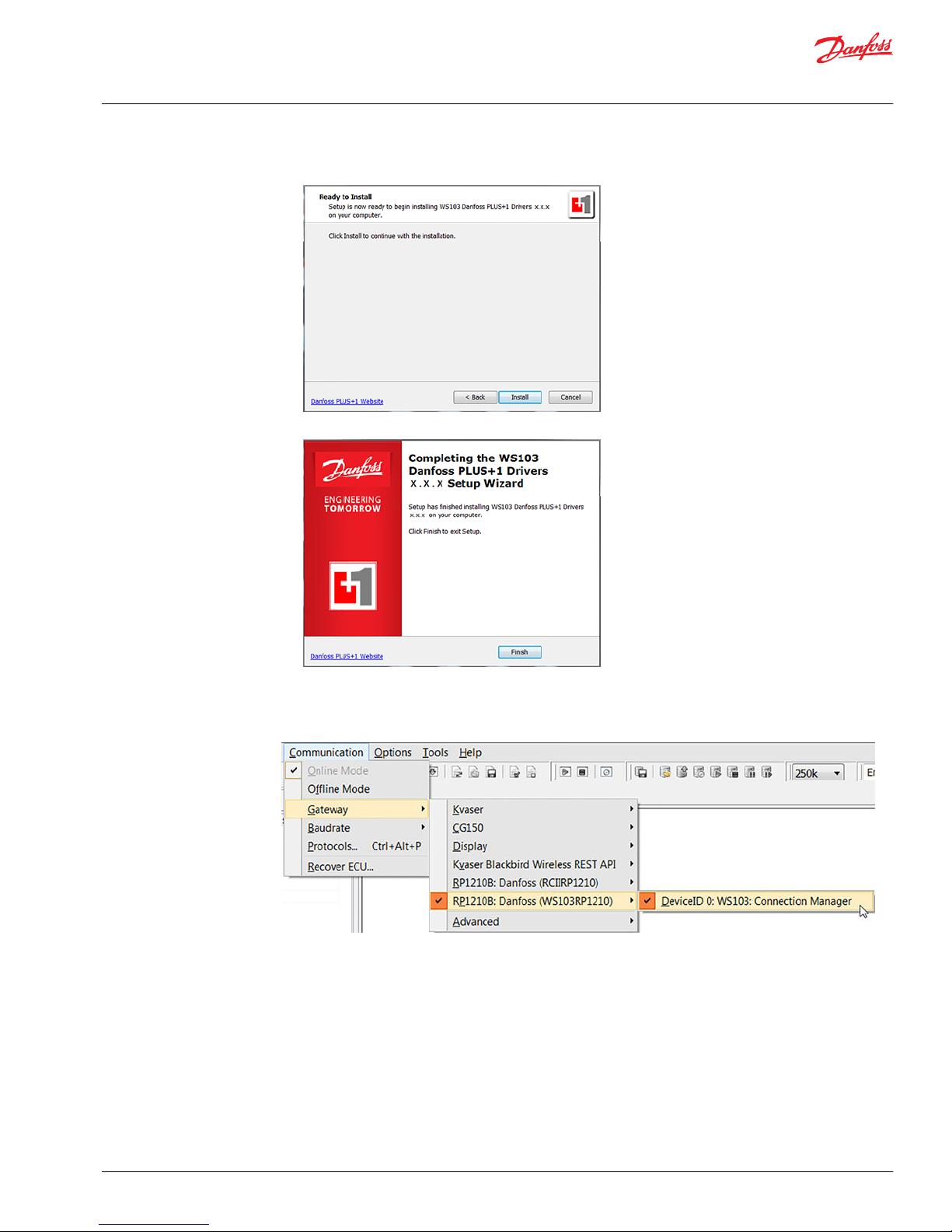
4. Click on Install.
5. Click on Finish.
The WS Wireless Configurator installation has installed successfully and will restart.
After the installation of the driver, start the PLUS+1® Service Tool program. Select Communication >
Gateway > RP1210B: Danfoss (WS103RP1210) > WS103 Connection Manager.
User Manual
WS103 Remote Solution
PLUS+1® Service Tool connected to a WS103
©
Danfoss | July 2016 AN00000339en-US0101 | 49
Page 50

Connections window
WS103 Connection Manager
The WS103 Connection Manager in the PLUS+1® Service Tool stores every new connection created by the
user. The next execution of the PLUS+1® Service Tool shows the list of available created wireless
connections.
WS103 Connection Manager push buttons
Push button Description
Add new connection
Delete Selected Connection
User Manual
WS103 Remote Solution
PLUS+1® Service Tool connected to a WS103
50 | © Danfoss | July 2016 AN00000339en-US0101
Page 51

WS103 Connection Manager push buttons (continued)
Push button Description
Move Up the selection from the selected connection
Move Down the selection from the selected connection
Stored wireless connections selection can be done directly in the gateway selection.
Add WLAN Infrastructure connection
Open PLUS+1® Service Tool and start the WS103 Connection manager.
1. Click on Add Connection
a) Write name of connection.
b) Select the WLAN type of connection.
c) Select the IP address assigned to a WS103 and the port.
For example: IP address 192.168.0.33 and Port:30000
d) Click Apply.
2. Click on Connect.
A pop up window will show the connection process in progress.
User Manual
WS103 Remote Solution
PLUS+1® Service Tool connected to a WS103
©
Danfoss | July 2016 AN00000339en-US0101 | 51
Page 52

When ST is connected the scan of the CAN bus will start.
After the scan of the system the ECU PLUS+1® compliance will be available on ST ECU list and the symbol
connected will be green.
A status dialog will open.
User Manual
WS103 Remote Solution
PLUS+1® Service Tool connected to a WS103
52 | © Danfoss | July 2016 AN00000339en-US0101
Page 53

Device Type WS103
SSID The SSID of the wireless network connected by WS103
Firmware The installed Firmware version
Safety Status The current state of the global safety mechanism (could be Write or Read Only access)
CAN Bus Status The current state of the CAN Bus
Connection The connection name created on the Connection Manager
IP Address The IP Address : Port used by WS103
Connection Time Current connection time
If error is indicated
Scan of multiple ECU available on the network indicate error E204 No Answer from ECU.
1. Select the menu Communications > Protocols.
a) Select PLUS+1® protocol, ID 0 in the list.
2. Set the parameter KW2000_STmin to 1 in the Edit field.
a) Click OK.
User Manual
WS103 Remote Solution
PLUS+1® Service Tool connected to a WS103
©
Danfoss | July 2016 AN00000339en-US0101 | 53
Page 54

Add Bluetooth® connection
Open PLUS+1® Service Tool and start the WS103 Connection manager
1. Click on Add Connection
a) Write name of connection.
b) Select the Bluetooth® type of connection.
c) Select the COM port assigned to a SPP_WS103.
d) Click Apply.
2. Click on Connect.
A pop up window will show the connection process in progress.
When ST is connected the scan of the CAN bus will start.
After the scan of the system the ECU PLUS+1® compliance will be available on ST ECU list and the symbol
connected will be green.
User Manual
WS103 Remote Solution
PLUS+1® Service Tool connected to a WS103
54 | © Danfoss | July 2016 AN00000339en-US0101
Page 55

A status dialog will open.
Device Type WS103
Name SPP_WS103-2
Firmware The installed Firmware version
Safety Status The current state of the global safety mechanism (could be Write or Read Only access)
CAN Bus Status The current state of the CAN Bus
Connection The connection name created on the Connection Manager
COM Port The COM port used for SPP service
Connection Time Current connection time
User Manual
WS103 Remote Solution
PLUS+1® Service Tool connected to a WS103
©
Danfoss | July 2016 AN00000339en-US0101 | 55
Page 56

If error is indicated
Scan of multiple ECU available on the network indicate error E204 No Answer from ECU.
1. Select the menu Communications > Protocols.
a) Select PLUS+1® protocol, ID 0 in the list.
2. Set the parameter KW2000_STmin to 1 in the Edit field.
a) Click OK.
WS Wireless Driver version
Identify the version of the WS Wireless Drivers by going to the Connection Manager and clicking About.
In the example below it’s showed the version 1.0.0.0
Example of version 1.0.0.0
User Manual
WS103 Remote Solution
PLUS+1® Service Tool connected to a WS103
56 | © Danfoss | July 2016 AN00000339en-US0101
Page 57

WS103 dimensions
WS103 dimensions (mm [in])
59.00 [02.32]
59.00
[02.32]
33.50 [01.32]
23.50 [0.925]
75.00
[02.95]
kwa1459375229783
Ø4.3
Ø4.3
WS103 connectors and indicator element
WS103 is equipped with the following connectors and indicator element
1
2
3
kwa1459393937324
1. CAN / Power connector
2. RS232 connector
3. Power / CAN / Status LED indicator element
User Manual
WS103 Remote Solution
Appendix A – Dimensions
©
Danfoss | July 2016 AN00000339en-US0101 | 57
Page 58

Direct screw install
WS103 device direct screw install
1
2
kwa1459380563336
1. WS103
2. M4 screws with internal-6kt / DIN 912 - ISO 4762, length = at least 25 mm
The module can be installed directly with two M4 cylinder screws with indoor 6kt DIN 912 / ISO 4762,
length = at least 25 mm. Tighten the mounting screws of the module with a torque of M = 0.9 N•m to 1.1
N•m.
•
DIN 6797 - external tooth lock washer is recommended.
•
For the distances between the holes, see WS103 dimensions on page 57.
•
The module can be mounted in any position, in the case of outdoor installation, place it in a way that
does not allow water or liquid on to the connectors, see Ingress protection rating on page 58
Ingress protection rating
W
Warning
International Protection Marking of IP 67 rating is not ensured if all connectors are not plugged in. Before
exposing the device to dust and water, plug in all connectors. Do not immerse the device in water or
other liquids. Make sure that WS devices are stored and transported at a temperature between -40 °C and
+85 °C or -40 °F and +185 °F respectively.
User Manual
WS103 Remote Solution
Appendix B – Mounting
58 | © Danfoss | July 2016 AN00000339en-US0101
Page 59

User Manual
WS103 Remote Solution
©
Danfoss | July 2016 AN00000339en-US0101 | 59
Page 60

Danfoss Power Solutions is a global manufacturer and supplier of high-quality hydraulic and
electronic components. We specialize in providing state-of-the-art technology and solutions
that excel in the harsh operating conditions of the mobile off-highway market. Building on
our extensive applications expertise, we work closely with our customers to ensure
exceptional performance for a broad range of off-highway vehicles.
We help OEMs around the world speed up system development, reduce costs and bring
vehicles to market faster.
Danfoss – Your Strongest Partner in Mobile Hydraulics.
Go to www.powersolutions.danfoss.com for further product information.
Wherever off-highway vehicles are at work, so is Danfoss. We offer expert worldwide support
for our customers, ensuring the best possible solutions for outstanding performance. And
with an extensive network of Global Service Partners, we also provide comprehensive global
service for all of our components.
Please contact the Danfoss Power Solution representative nearest you.
Local address:
Danfoss
Power Solutions GmbH & Co. OHG
Krokamp 35
D-24539 Neumünster, Germany
Phone: +49 4321 871 0
Danfoss
Power Solutions ApS
Nordborgvej 81
DK-6430 Nordborg, Denmark
Phone: +45 7488 2222
Danfoss
Power Solutions (US) Company
2800 East 13th Street
Ames, IA 50010, USA
Phone: +1 515 239 6000
Danfoss
Power Solutions Trading
(Shanghai) Co., Ltd.
Building #22, No. 1000 Jin Hai Rd
Jin Qiao, Pudong New District
Shanghai, China 201206
Phone: +86 21 3418 5200
Danfoss can accept no responsibility for possible errors in catalogues, brochures and other printed material. Danfoss reserves the right to alter its products without notice. This also applies to products
already on order provided that such alterations can be made without changes being necessary in specifications already agreed.
All trademarks in this material are property of the respective companies. Danfoss and the Danfoss logotype are trademarks of Danfoss A/S. All rights reserved.
©
Danfoss | July 2016 AN00000339en-US0101
Products we offer:
•
Bent Axis Motors
•
Closed Circuit Axial Piston
Pumps and Motors
•
Displays
•
Electrohydraulic Power
Steering
•
Electrohydraulics
•
Hydraulic Power Steering
•
Integrated Systems
•
Joysticks and Control
Handles
•
Microcontrollers and
Software
•
Open Circuit Axial Piston
Pumps
•
Orbital Motors
•
PLUS+1® GUIDE
•
Proportional Valves
•
Sensors
•
Steering
•
Transit Mixer Drives
Comatrol
www.comatrol.com
Schwarzmüller-Inverter
www.schwarzmuellerinverter.com
Turolla
www.turollaocg.com
Hydro-Gear
www.hydro-gear.com
Daikin-Sauer-Danfoss
www.daikin-sauer-danfoss.com
 Loading...