

Page 1
Fact sheet
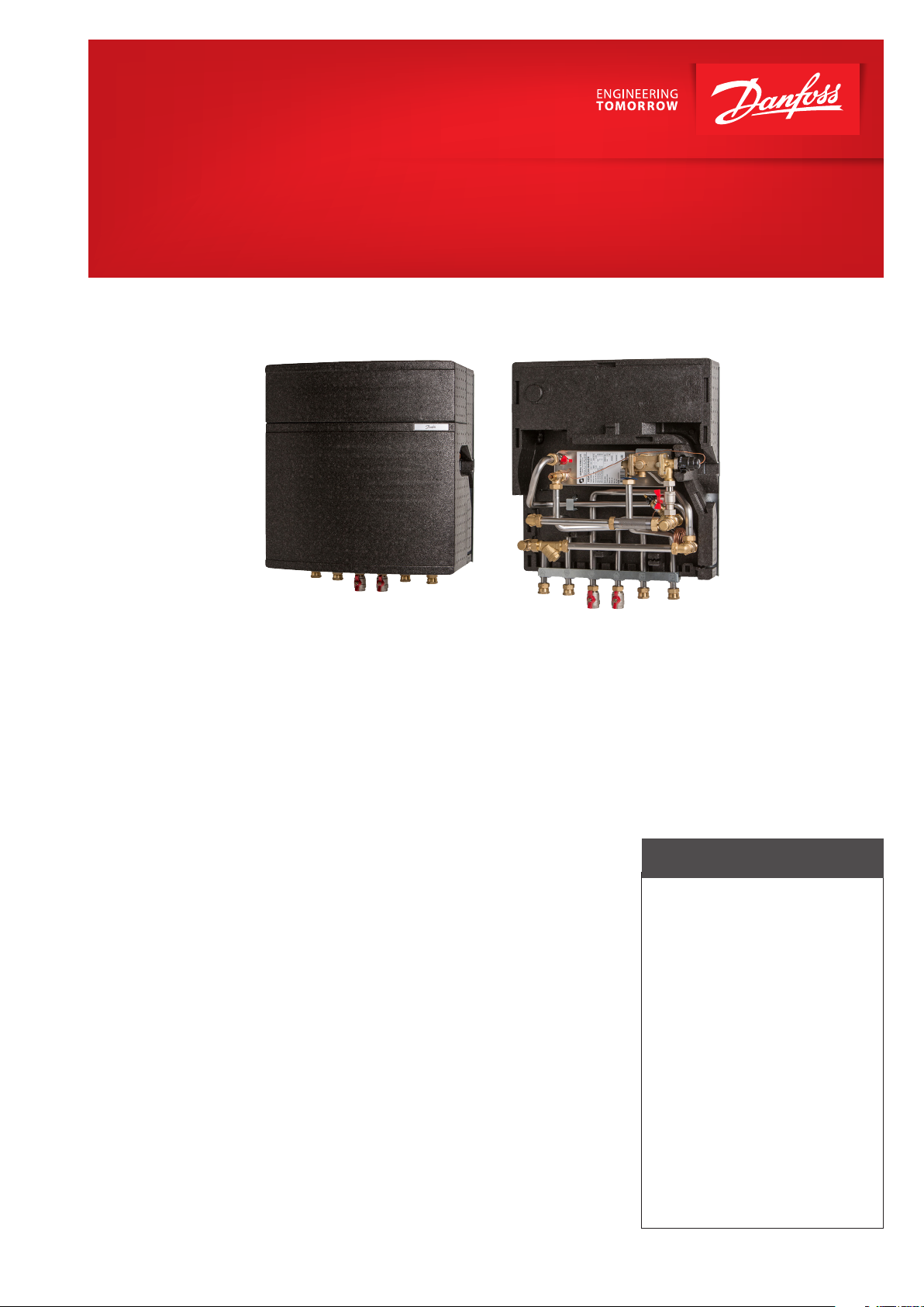
Termix VMTD-I-FI
Direct substation for flats and single family houses
Application
The Termix VMTD-I-FI is a complete solution
with a built-in water heater and a differential pressure controlled heating system. Termix VMTD-I-FI is applicable for single family
houses and for decentralized systems.
District heating (DH)
The substation is prefabricated with a differential pressure controller, a fitting piece
and a sensor pocket for insertion of a heat
meter as well as strainer and ball valves. The
display of the heat meter is to be mounted
behind the removable inspection cover at
the top of the unit.
Heating (HE)
The heating circuit is designed for direct
generation of heat. The differential pressure controller sets the optimum operation
conditions for radiator thermostatic valves
enabling individual temperature control in
each room.
Domestic hot water (DHW)
The domestic hot water is prepared in the
heat exchanger and the temperature is regulated with a flow-compensated temperature controller with integrated differential
pressure controller. The DH water is cooled
very efficiently by the heat exchanger,
thereby creating an excellent operating
economy. The Danfoss IHPT valve ensures
a stable domestic hot water temperature
by varying loads, varying supply temperatures and by high and varying differential
pressure without the need for readjusting
the valve. This protects the heat exchanger against overheating and lime scale formation. Furthermore the IHPT valve has
an integrated idle temperature controller,
which keeps the house supply line warm.
This shortens the waiting periods during
summer when the heating system is in reduced operation, which is ideal where high
comfort is requested.
Options
The Termix VMTD-I-FI can be supplied with
a connection for circulation.
Construction
All pipes are made of stainless.The connections are made by nuts and gaskets.
Insulation
The Termix VMTD-I-FI comes complete
with a fully insulated cover thus minimizing the heat loss both during tapping of
domestic hot water but also when only
space heating is required.
FEATURES AND BENEFITS
• Substation for DH and
decentralized systems
• Direct heating with differential
pressure controller
• DHW flow-compensated
temperature controller
• Capacity: 32 - 61 kW for DHW
• DHW in sufficient quantity
• Operates independently of differential
pressure and flow temperature
• Minimum space required for installation
• Pipes and plate heat exchanger
made of stainless steel
• Minimized risk of lime scale
and bacteria formation
• Low heat loss
www.danfoss.com
Page 2
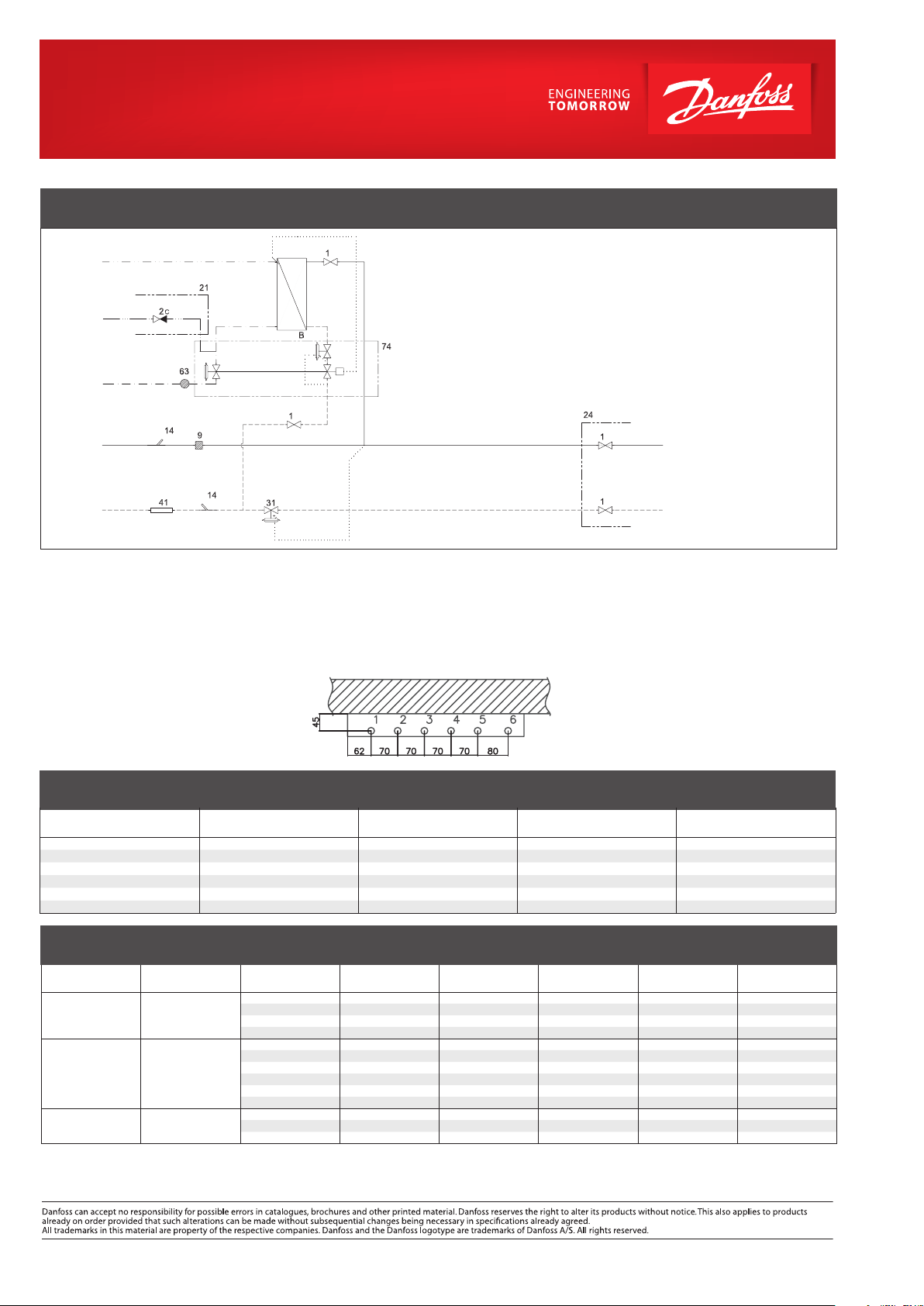
CIRCUIT DIAGRAM - EXAMPLE
DHW
Circ.
CWM
1 Ball valve
B Heat exchanger
9 Strainer
14 Sensor pocket, energy meter
21 To be ordered separately
24 Delivered loose with unit
31 Differential pressure controller
41B Fitting piece, energy meter ¾” x 110 mm
63 Sieve
72 IHPT
DH
Supply
DH
Return
Technical parameters:
Nominal pressure: PN 10
DH supply temperature: T
DCW static pressure: p
Brazing material (HEX): Copper
= 120 °C
max
= 1 bar
min
Weight incl. insulation: 20 kg
(incl. packing)
Insulation cover: Anthracite grey EPP
Dimensions (mm):
With insulation (mounted on wall variant)
H 660 × W 540 × D 335 mm
HEATING: CAPACITY EXAMPLES
Substation type
Ter mix
VMTD-I-FI 1/2/3 15 75/30 15 287
VMTD-I-FI 1/2/3 15 80/30 10 258
VMTD-I-FI 1/2/3 15 90/30 10 215
VMTD-I-FI 1/2/3 19 75/40 40 467
VMTD-I-FI 1/2/3 19 80/45 40 467
VMTD-I-FI 1/2/3 19 90/50 30 409
Heating capacity
[ kW ]
Connections:
1 District heating (DH) supply
2 District heating (DH) return
3 Heating (HE) supply
4 Heating (HE) return
5 Domestic hot water (DHW)
6 Domestic cold water (DCW)
Heating circuit
t ∆t [ °C ]
HE
Supply
HE
Return
Connections sizes:
DH + HE: G ¾” (int. thread)
DCW + DHW: G ¾” (int. thread)
Options:
• Safety valve and non-return valve
(10 bar)
• Thermostatic circulation set
• Pressure compensation valve (GTU)
• Connection for hot water circulation
Pressure loss
[ kPa ]
Flow rate
[ l / h]
DHW: CAPACITY EXAMPLES
CAPACITY, WEIGHT AND DIMENSIONS
Substation type
VMTD-I-FI 1
VMTD-I-FI 2
VMTD-I-FI 3
Plate heat
exchanger
XB06-H+ 26
IHPT 3,0
XB06-H+ 40
IHPT 3,0
XB06-H+ 60
IHPT 3,0
DHW capacity
[ kW ]
32.3 60 16 45 27 13.3
43.0 60 17 45 45 17.7
37.0 70 16 50 22 13.3
51.0 70 17 50 42 18.4
32.3 55 17 45 25 13.3
43.0 55 18 45 45 17.7
32.3 60 15 45 20 13.3
49.0 60 16 45 42 20.2
39.0 70 15 50 19 14.1
58.0 70 16 50 40 20.9
42.0 55 16 45 35 17.3
49.0 60 15 45 35 20.2
61.0 70 15 50 35 22.0
Supply flow
primar y [ °C ]
Return flow
primar y [ °C ]
DHW
[ °C ]
Gemina Termix A/S · Member of the Danfoss Group · Navervej 15-17 · DK-7451 Sunds · Denmark
Tel.: +45 9714 1444 · Fax: +45 9714 1159 · mail@termix.dk · www.heating.danfoss.com
© Danfoss | DHS-SMDT/ PL | 2021 . 03
Pressure loss
primar y [ kPa ]
DHW tap load
[ l / min]
AM372950227872en-000101
 Loading...