

Page 1
OperatingGuide
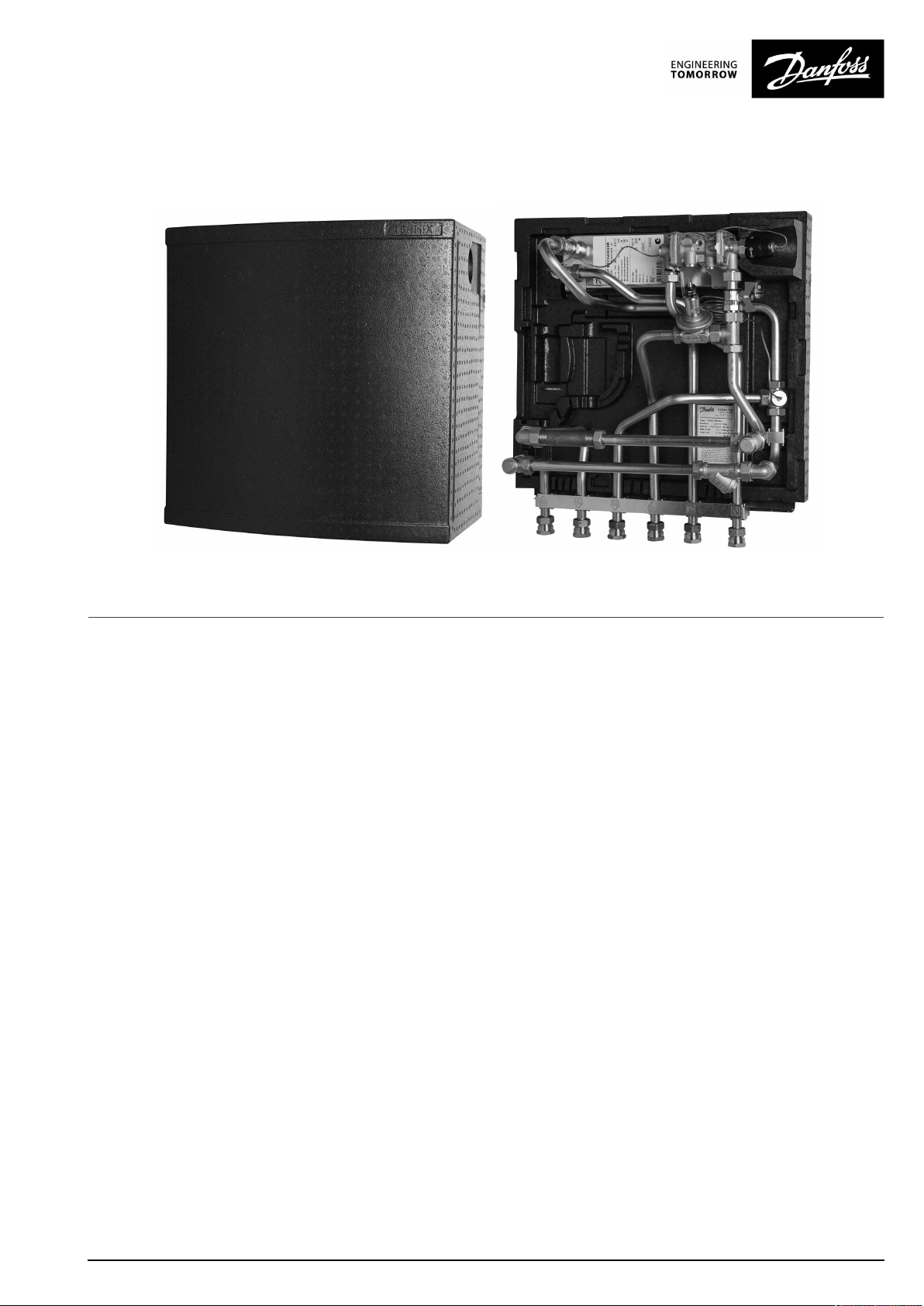
TermixVMTD-Iwithcompleteinsulation
1.0TableofContents
1.0TableofContents.............................................1
........................................................................2
2.0VMTD-IinsuIHPTFunctionaldescription...........3
3.0Safetynotes.....................................................4
3.1SafetyNotes–general............................................4
4.0Mounting........................................................5
4.1Mounting...........................................................5
4.2Start-up..............................................................7
5.0Design.............................................................8
5.1Design...............................................................8
5.2Schematicdiagram................................................9
6.0Controls..........................................................10
6.1Heatingcircuit......................................................10
6.2DHWtemperaturecontrol........................................11
6.3Other.................................................................12
6.4Extras................................................................14
6.5Mountingplateforenergymeterdisplay.....................15
6.6Maintenance........................................................16
7.0Troubleshooting..............................................17
7.1Troubleshootingingeneral......................................17
7.2TroubleshootingDHW............................................18
7.3TroubleshootingHE...............................................19
7.4Disposal.............................................................21
8.0Declaration......................................................22
8.1Declarationofconformity........................................22
©Danfoss|2019.05VM.IE.C3.02/LUK40143|1
Page 2

OperatingGuideT ermixVMTD-Iwithcompleteinsulation
2|©Danfoss|2019.05
VM.IE.C3.02/LUK40143
Page 3
OperatingGuideT ermixVMTD-Iwithcompleteinsulation
2.0VMTD-IinsuIHPTFunctionaldescription
Districtheatingsubstationfordirectheatingand
instantaneousdomestichotwaterwithflow-compensated
temperaturecontroller .Designedforwall-mounting.
Application
TheTermixVMTD-Iisacompletesolutionwithbuilt-inwaterheater
andadifferentialpressurecontrolledheatingsystem.Termix
VMTD-Iisapplicableforsinglefamilyhousesandfordecentralized
systems.
Districtheating(DH)
Thesubstationisprefabricatedwithadifferentialpressure
controller,afittingpieceandsensorpocketsforinsertionofan
energymeteraswellasstrainer.Thedisplayoftheenergymeteris
tobemountedonabracketunderneaththesubstation.
Heating(HE)
Theheatingcircuitisdesignedfordirectgenerationofheat.
Thedifferentialpressurecontrolsetstheoptimumoperation
conditionsforradiatorthermostaticvalvesinordertoenable
individualtemperaturecontrolineachroom.Inordertoenablea
time-dependingtemperaturecontrolprogram,azonevalvewith
actuatorisincluded,andaroomthermostatcanbeincludedas
anoption.
Domestichotwater(DHW)
Thedomestichotwaterispreparedintheheatexchangerandthe
temperatureisregulatedwithaflowcompensatedtemperature
controllerwithintegrateddifferentialpressurecontroller.Theheat
exchanger-whichisinsulated-coolstheDHwaterveryefficiently,
therebycreatinganexcellentoperatingeconomy.TheIHPTvalve
ensuresastablehotwatertemperaturebyvaryingloads,supply
temperaturesandbyhighandvaryingdifferentialpressurewithout
theneedforreadjustingthevalve.Thisprotectstheheatexchanger
againstoverheatingandlimescaleformation.Furthermorethe
IHPTvalvehasanintegratedidletemperaturecontroller,which
keepsthehousesupplylinewarm.Thisshortensthewaiting
periodsduringsummerwhentheheatingsystemisinreduced
operation,whichisidealwherehighcomfortisrequested.AWRAS
approvednon-returnvalveisfittedinthecoldwatersupply.
VM.IE.C3.02/LUK40143
©Danfoss|2019.05|3
Page 4
OperatingGuideT ermixVMTD-Iwithcompleteinsulation
3.0Safetynotes
3.1SafetyNotes–general
Thefollowinginstructionsrefertothestandarddesignof
substation.Specialversionsofsubstationsareavailableon
request.
Thisoperatingmanualshouldbereadcarefullybeforeinstallation
andstart-upofthesubstation.Themanufactureracceptsno
liabilityfordamageorfaultsthatresultfromnon-compliancewith
theoperatingmanual.Pleasereadandfollowalltheinstructions
carefullytopreventaccidents,injuryanddamagetoproperty.
Assembly,start-upandmaintenanceworkmustbeperformedby
qualifiedandauthorizedpersonnelonly.
Pleasecomplywiththeinstructionsissuedbythesystem
manufacturerorsystemoperator.
Corrosionprotection
Allpipesandcomponentsaremadeofstainlesssteelandbrass.
Themaximumchloridecompoundsoftheflowmediumshouldnot
behigherthan150mg/l.
Theriskofequipmentcorrosionincreasesconsiderablyifthe
recommendedlevelofpermissiblechloridecompoundsis
exceeded.
Energysource
Thesubstationisdesignedfordistrictheatingastheprimary
sourceofenergy.However,alsootherenergysourcescanbeused
wheretheoperatingconditionsallowitandalwaysarecomparable
todistrictheating.
Application
Thesubstationisdesignedtobeconnectedtothehouse
installationinafrost-freeroom,wherethetemperaturedoesnot
exceed50°Candthehumiditydoesnotexceed60%.Donotcover
orwallupthesubstationorinanyotherwayblocktheentrance
tothestation.
Authorizedpersonnelonly
Assembly,start-upandmaintenanceworkmustbeperformedby
qualifiedandauthorizedpersonnelonly.
Pleaseobserveinstructionscarefully
Toavoidinjurytopersonsanddamagetothedevice,itisabsolutely
necessarytoreadandobservetheseinstructionscarefully.
Warningofhighpressureandtemperature
Beawareoftheinstallation’spermissiblesystempressureand
temperature.
Themaximumtemperatureoftheflowmediuminthesubstationis
120°C.
Themaximumoperatingpressureofthesubstationis10bar.PN16
versionsareavailableonenquiry.
Theriskofpersonsbeinginjuredandequipmentdamagedincreases
considerablyiftherecommendedpermissibleoperatingparameters
areexceeded.
Thesubstationinstallationmustbeequippedwithsafetyvalves,
however,alwaysinaccordancewithlocalregulations.
Choiceofmaterial
Choiceofmaterialsalwaysincompliancewithlocallegislation.
Safetyvalve(s)
Werecommendmountingofsafetyvalve(s),however,alwaysin
compliancewithlocalregulations.
Connection
Thesubstationmustbeequippedwithfeaturesthatensurethat
thesubstationcanbeseparatedfromallenergysources(also
powersupply).
Emergency
Incaseofdangeroraccidents-fire,leaksorotherdangerous
circumstances-interruptallenergysourcestothestationif
possible,andseekexperthelp.
Incaseofdiscolouredorbad-smellingdomestichotwater,closeall
shut-offvalvesonthesubstation,informtheoperatingpersonnel
andcallforexperthelpimmediately.
REACH
AllDanfossA/SproductsfulfilltherequirementsinREACH.
OneoftheobligationsinREACHistoinformcustomersabout
presenceofCandidatelistsubstancesifany,weherebyinform
youaboutonesubstanceonthecandidatelist:Theproduct
containsbrasspartswhichcontainslead(CASno:7439-92-1)ina
concentrationabove0.1%w/w.
Storage
Anystorageofthesubstationwhichmaybenecessarypriorto
installationshouldbeinconditionswhicharedryandheated.
Warningofhotsurface
Thesubstationhasgothotsurfaces,whichcancauseskinburns.
Pleasebeextremelycautiousincloseproximitytothesubstation.
Powerfailurecanresultinthemotorvalvesbeingstuckinopen
position.Thesurfacesofthesubstationcangethot,whichcancause
skinburns.Theballvalvesondistrictheatingsupplyandreturnshould
beclosed.
Warningoftransportdamage
Beforesubstationinstallation,pleasemakesurethatthesubstation
hasnotbeendamagedduringtransport.
IMPORTANT-Tighteningofconnections
Duetovibrationsduringtransportallflangeconnections,screwjoints
andelectricalclampandscrewconnectionsmustbecheckedand
tightenedbeforewaterisaddedtothesystem.Afterwaterhasbeen
addedtothesystemandthesystemhasbeenputintooperation,
re-tightenALLconnections.
4|©Danfoss|2019.05
VM.IE.C3.02/LUK40143
Page 5
OperatingGuideT ermixVMTD-Iwithcompleteinsulation
4.0Mounting
4.1Mounting
Installationmustbeincompliancewithlocalstandardsand
regulations.
Districtheating(DH)-Inthefollowingsections,DHreferstothe
heatsourcewhichsuppliesthesubstations.Avarietyofenergy
sources,suchasoil,gasorsolarpower,couldbeusedasthe
primarysupplytoDanfosssubstations.Forthesakeofsimplicity,
DHcanbetakentomeantheprimarysupply.
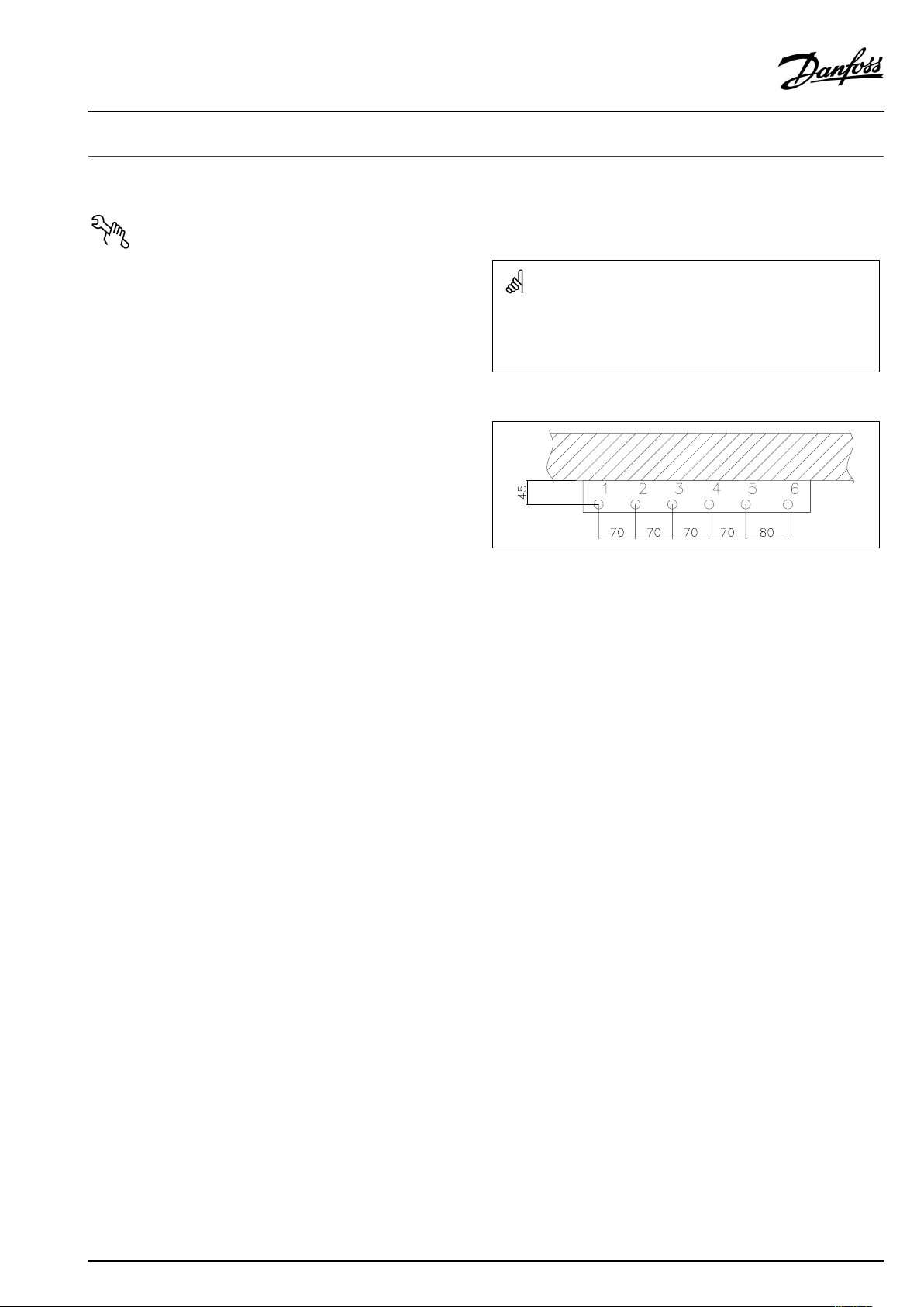
Connections:
1.Districtheating(DH)supply
2.Districtheating(DH)return
3.Heating(HE)supply
4.Heating(HE)return
5.Domestichotwater(DHW)
6.Domesticcoldwater(DCW)
Authorizedpersonnelonly
Assembly,start-upandmaintenanceworkmustbeperformedby
qualifiedandauthorizedpersonnelonly.
Connectionsizes:
DH+HE:
DCW+DHW:
Dimensions(mm):
Withinsulation:
H610xW540xD345
Weight(approx.):15kg
Thepipeplacementcandeviatefromtheshowndrawing.Pleasenote
themarkingsonthestation.
G¾”(int.thread)
G¾”(int.thread)
VM.IE.C3.02/LUK40143
©Danfoss|2019.05|5
Page 6
OperatingGuideT ermixVMTD-Iwithcompleteinsulation
4.1.1Installation
Mounting:
Adequatespace
Pleaseallowadequatespacearoundthesubstationformounting
andmaintenancepurposes.
Orientation
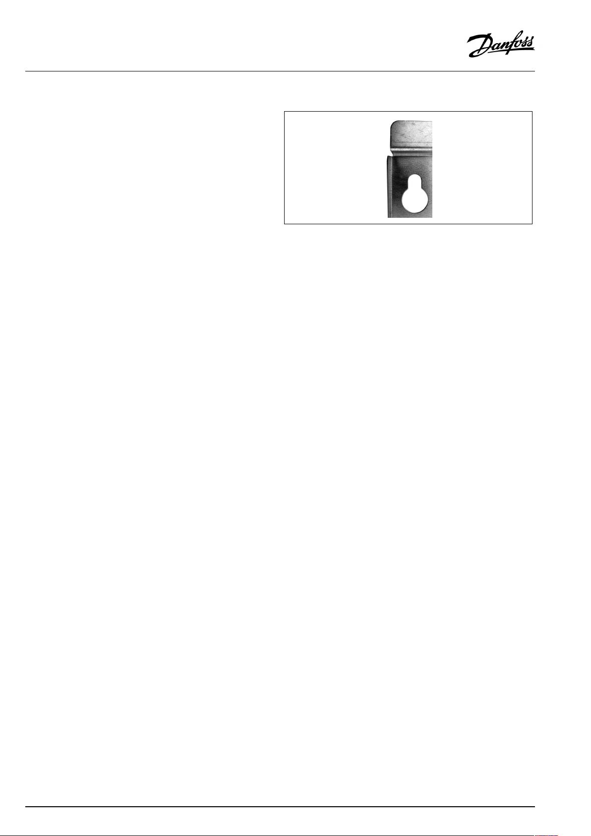
Thestationmustbemountedsothatcomponents,keyholes
andlabelsareplacedcorrectly.Ifyouwishtomountthestation
differentlypleasecontactyoursupplier.
Drillings
Wheresubstationsaretobewall-mounted,drillingsareprovided
inthebackmountingplate.Floormountedunitshavesupport.
Labelling
Eachconnectiononthesubstationislabelled.
Beforeinstallation:
Cleanandrinse
Priortoinstallation,allsubstationpipesandconnectionsshouldbe
cleanedandrinsed.
Keyholeformounting.
Tightening
Duetovibrationduringtransport,allsubstationconnectionsmust
becheckedandtightenedbeforeinstallation.
Unusedconnections
Unusedconnectionsandshut-offvalvesmustbesealedwitha
plug.Shouldtheplugsrequireremoval,thismustonlybedoneby
anauthorizedservicetechnician.
Installation:
Strainer
Ifastrainerissuppliedwiththestationitmustbefittedaccording
toschematicdiagram.Pleasenotethatthestrainermaybe
suppliedloose.
Connections
Internalinstallationanddistrictheatingpipesconnectionsmustbe
madeusingthreaded,flangedorweldedconnections.
6|©Danfoss|2019.05
VM.IE.C3.02/LUK40143
Page 7
OperatingGuideT ermixVMTD-Iwithcompleteinsulation
4.2Start-up
Start-up,Directheating
Theshut-offvalvesshouldbeopenedandtheunitobservedas
itentersservice.Visualcheckingshouldconfirmtemperatures,
pressures,acceptablethermalexpansionandabsenceofleakage.
Iftheheatexchangeroperatesinaccordancewithdesign,itcanbe
puttoregularuse.
Afterwaterhasbeenaddedtothesystemandthesystemhasbeen
putintooperation,re-tightenALLconnections.
Re-thightenconnections
Afterwaterhasbeenaddedtothesystemandthesystemhasbeen
putintooperation,re-tightenALLconnections.
VM.IE.C3.02/LUK40143
©Danfoss|2019.05|7
Page 8
OperatingGuideT ermixVMTD-Iwithcompleteinsulation
5.0Design
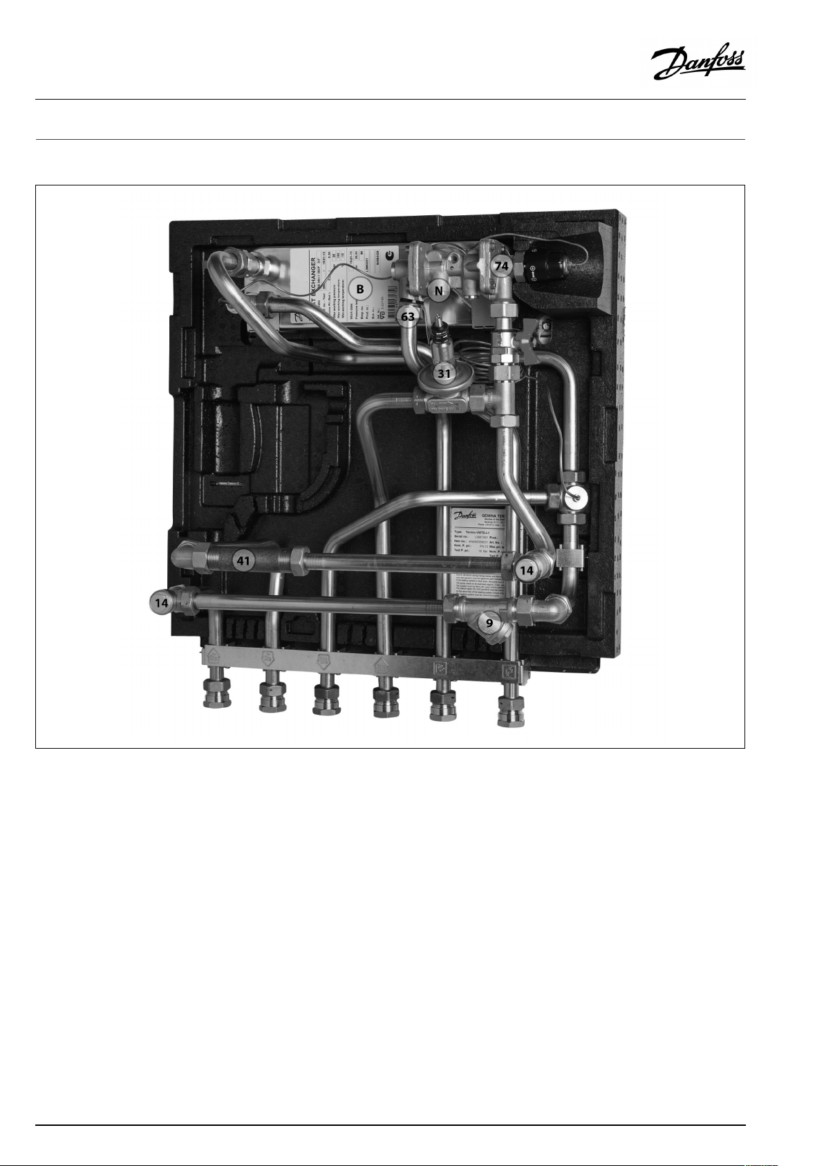
5.1Design
Yoursubstationmightlookdifferentthanthesubstationshown.
Designdescription
B
Heatexchanger,DHW
N
Circulationconnection
9
Strainer
14
Sensorpocket,energymeter
8|©Danfoss|2019.05
31
Differentialpressurecontroller
41
Fittingpiece,energymeter
63
Sieve
74
IHPTcontroller,DHW
VM.IE.C3.02/LUK40143
Page 9

OperatingGuideT ermixVMTD-Iwithcompleteinsulation
5.2Schematicdiagram
DHW
DCW
DH
Supply
DH
Return
Yoursubstationmightlookdifferentthantheschematicdiagramshown.
Schematicdescription
B
Heatexchanger,DHW
1
Ballvalve
9
Strainer
DHW:DomesticHotWater
DCW:
DHSupply:DistrictHeatingSupply
DHReturn:DistrictHeatingReturn
HESupply:HeatingSupply
HEReturn:HeatingReturn
DomesticColdWater
14
Sensorpocket,heatmeter
31
Differentialpressurecontroller
39
Connectionclosed
41
Fittingpiece,energymeter
63
Sieve
74
IHPTcontroller
HE
Supply
HE
Return
5.2.1Technicalparameters
Technicalparameters
Nominalpressure:PN10(PN16versionsareavailableonenquiry)
Max.DHsupplytemperature:
Min.DCWstaticpressure:
Brazingmaterial(HEX):
Heatexchangerstestpressure:30bar
Soundlevel:≤55dB
VM.IE.C3.02/LUK40143
120°C
1.0bar
Copper
©Danfoss|2019.05|9
Page 10

OperatingGuideT ermixVMTD-Iwithcompleteinsulation
6.0Controls
6.1Heatingcircuit
6.1.1Differentialpressurecontroller
Thedifferentialpressurecontrollersmoothsoutthefluctuationsin
pressurearrivingfromthedistrictheatingnetwork.Theoperating
pressureinthesubstationisthusheldsteady.
10|©Danfoss|2019.05
VM.IE.C3.02/LUK40143
Page 11

OperatingGuideT ermixVMTD-Iwithcompleteinsulation
6.2DHWtemperaturecontrol
DHWtemperaturecontrol
TherearevarioustypesofDHWtemperaturecontrolusedin
Danfosssubstations.
DHWtemperatureshouldbeadjustedto45-50°C,asthisprovides
optimalutilisationofDHwater.AtDHWtemperaturesabove55°C,
thepossibilityoflimescaledepositsincreasessignificantly.
6.2.1IHPT90controller(45–65°)
IHPTisaself-actingflow-compensatedtemperaturecontrollerwith
integrateddifferentialpressurecontroller.
TheIHPToperatesatitsbestatDHsupplytemperaturesofupto
100°C.
Byturningthehandlefortemperaturesettingin(+)direction
thesettingisincreased,byturningitin(-)directionthesettingis
decreased.
Turns*
0
1
2
3
4
5
6
7
*Startposition:Handleturnedfullyin(+)direction.
Thevaluesareintendedasaguide.
Scale
7
661
5
455
352
248
144
043
DHWT emperatureSetting[°C]
64
58
VM.IE.C3.02/LUK40143
©Danfoss|2019.05|11
Page 12

OperatingGuideT ermixVMTD-Iwithcompleteinsulation
6.3Other
6.3.1Safetyvalve
Thepurposeofthesafetyvalveistoprotectthesubstationfrom
excessivepressure.
Theblow-offpipefromthesafetyvalvemustnotbeclosed.The
blow-offpipeoutletshouldbeplacedsothatitdischargesfreely
anditispossibletoobserveanydrippingfromthesafetyvalve.
Itisrecommendedtochecktheoperationofsafetyvalvesat
intervalsof6months.Thisisdonebyturningthevalveheadin
directionindicated.
6.3.2Strainer
Strainersshouldbecleanedregularlybyauthorizedpersonnel.The
frequencyofcleaningwoulddependonoperatingconditionsand
themanufacturer’sinstructions.
6.3.3GTUPressureEqualizer
TheGTUPressureEqualizerabsorbstheexpansiononthe
secondarysideoftheTermixwaterheatersandcanbeusedasa
substitutetothesafetyvalve.
Furthermorethepressureequalizerabsorbsapossibleincreasein
pressure,soadischargeoutletisomitted.
TheGTUPressureEqualizermaynotbeappliedinsystemswithhot
watercirculation.
12|©Danfoss|2019.05
VM.IE.C3.02/LUK40143
Page 13

OperatingGuideT ermixVMTD-Iwithcompleteinsulation
6.3.4Fittingpiece
Thesubstationisequippedwithafittingpieceforenergymeter.
Assemblyofenergymeters:
1:Closeballvalves
ClosetheballvalvesonDHSupplyandDHReturn,ifthereiswater
onthesystem.
2:Loosennuts
Loosenthenutsonthefittingpiece.
3:Removefittingpiece
Removethefittingpieceandreplaceitwiththeenergymeter.Do
notforgetthegaskets.
4:Tightenconnections
Aftermountingoftheenergymeterremembertocheckand
tightenallthreadedconnections.
Sensorpocket,energymeter
Thesensorsoftheenergymeterismountedinthesensorpockets.
VM.IE.C3.02/LUK40143
©Danfoss|2019.05|13
Page 14

OperatingGuideT ermixVMTD-Iwithcompleteinsulation
6.4Extras
6.4.1Circulationpipe
Thecirculationpipesetismounteddirectlyonthecontroller.
Thesetincludescirculationpipe,singlecheckvalveandfitting.
Whenmountingthehotwatercirculationdirectlyonthecontroller
thehotwatercirculationtemperaturewillbeequaltotheidle
temperature.Theidletemperatureisafewdegreeslowerthanthe
setdomestichotwatertemperature.
14|©Danfoss|2019.05
VM.IE.C3.02/LUK40143
Page 15

OperatingGuideT ermixVMTD-Iwithcompleteinsulation
6.5Mountingplateforenergymeterdisplay
Bracketforthedisplayoftheenergymeterdeliveredloosewith
theDistrictHeatingsubstation.
Mountthewallclipforthedisplayontothebracket.
Fixthebracketontothepipeclipsusingapairofpliers.
Slidethedisplayoftheenergymeterontheclip.
ThedisplayisnowneatlypositionedbelowtheDistrictHeating
substation.
VM.IE.C3.02/LUK40143
©Danfoss|2019.05|15
Page 16

OperatingGuideT ermixVMTD-Iwithcompleteinsulation
6.6Maintenance
Thesubstationrequireslittlemonitoring,apartfromroutine
checks.Itisrecommendedtoreadtheenergymeteratregular
intervals,andtowritedownthemeterreadings.
RegularinspectionsofthesubstationaccordingtothisInstruction
arerecommended,whichshouldinclude:
Strainers
Cleaningofstrainers.
Meters
Checkingofalloperatingparameterssuchasmeterreadings.
Temperatures
Checkingofalltemperatures,suchasDHsupplytemperatureand
DHWtemperature.
Connections
Checkingallconnectionsforleakages.
Safetyvalves
Theoperationofthesafetyvalvesshouldbecheckedbyturning
thevalveheadintheindicateddirection.
Venting
Checkingthatthesystemisthoroughlyvented.
Authorizedpersonnelonly
Assembly,start-upandmaintenanceworkmustbeperformedby
qualifiedandauthorizedpersonnelonly.
Inspectionsshouldbecarriedoutminimumeverytwoyears.
SparepartscanbeorderedfromDanfoss.Pleaseensurethatany
enquiryincludesthesubstationserialnumber.
16|©Danfoss|2019.05
VM.IE.C3.02/LUK40143
Page 17

OperatingGuideT ermixVMTD-Iwithcompleteinsulation
7.0Troubleshooting
7.1Troubleshootingingeneral
Intheeventofoperatingdisturbances,thefollowingbasicfeatures
shouldbecheckedbeforecarryingoutactualtroubleshooting:
•thesubstationisconnectedtoelectricity,
•thestrainerontheDHsupplypipeisclean,
•thesupplytemperatureoftheDHisatthenormallevel
(summer,atleast60°C-winter,atleast70°C),
•thedifferentialpressureisequaltoorhigherthanthenormal
(local)differentialpressureintheDHnetwork–ifindoubt,ask
theDHplantsupervisor,
•pressureonthesystem-checktheHEpressuregauge.
Authorizedpersonnelonly
Assembly,start-upandmaintenanceworkmustbeperformedby
qualifiedandauthorizedpersonnelonly.
VM.IE.C3.02/LUK40143
©Danfoss|2019.05|17
Page 18

OperatingGuideT ermixVMTD-Iwithcompleteinsulation
7.2TroubleshootingDHW
ProblemPossiblecauseSolution
ToolittleornoDHW.
Taptemperaturetoohigh;DHWtapload
toohigh.
Temperaturedropduringtapping.
Thermostaticcontrolvalvedoesnotclose
Idletemperaturetoolow(forstations
equippedwithIHPT).
Strainerinsupplyorreturnlineclogged.Cleanstrainer(s).
DHWcirculationpumpoutoforderorwith
toolowsetting.
Defectiveorcloggednon-returnvalve.
Noelectricity.Check.
Wrongsettingofautomaticcontrols,ifany.Toadjustanelectroniccontrollerfor
Scalingoftheplateheatexchanger.
Defectivemotorizedvalve.Check(usemanualfunction)–replace.
Defectivetemperaturesensors.
Defectivecontroller.
DCWisbeingmixedwiththeDHW,e.g.ina
defectivethermostaticmixingvalve.
Defectiveorcloggednon-returnvalveon
circulationvalve.
Thermostaticvalveadjustedtoatoohigh
level.
Scalingoftheplateheatexchanger.
LargerDHWflowthanthesubstationhas
beendesignedfor.
TemperaturedifferencebetweenDH
supplyandDHWsetpointtoolow.
Setpointtoolow.Turnthermostatin(+)direction.
Checkcirculationpump.
Replace–clean.
DHW,pls.noteenclosedinstructionsfor
electroniccontroller.
Replace–rinseout.
Check–replace.
Check–replace.
Check–replace. Hotwaterinsometapsbutnotinall.
Replace–clean.
Check–set.
Replace–rinseout.
ReduceDHWflow.
Lowerthesetpointtemperatureorincrease
theDHsupplytemperature.
18|©Danfoss|2019.05
VM.IE.C3.02/LUK40143
Page 19

OperatingGuideT ermixVMTD-Iwithcompleteinsulation
7.3TroubleshootingHE
ProblemPossiblecauseSolution
Toolittleornoheat.StrainercloggedinDHorHEcircuit
Unevenheatdistribution.Airpocketsinthesystem.Venttheinstallationthoroughly.
DHsupplytemperaturetoohigh.
DHsupplytemperaturetoolow.
(radiatorcircuit).
ThefilterintheenergymeteronDHcircuit
clogged.
Defectiveorwronglyadjusteddifferential
pressurecontroller.
Sensordefective–orpossiblydirtinthe
valvehousing.
Automaticcontrols,ifany,wronglysetor
defective-possiblypowerfailure.
Pumpoutofoperation.Checkifthepumpisreceivingpowerand
Thepumpissetattoolowspeedof
rotation.
Pressuredrop–thepressuredropon
theradiatorcircuitshowslowerthan
recommendedoperatingpressure.
Airpocketsinthesystem.Venttheinstallationthoroughly.
Limitingofthereturntemperatureadjusted
toolow.
Defectiveradiatorvalves.
Unevenheatdistributioninbuilding
becauseofincorrectlysetbalancingvalves,
orbecausetherearenobalancingvalves.
Diameterofpipetosubstationtoosmallor
branchpipetoolong.
Wrongsettingofthermostatorof
automaticcontrols,ifany.
Defectivecontroller.Thecontrollerdoes
notreactasitshouldaccordingtothe
instructions.
Defectivesensoronself-actingthermostat.
Wrongsettingofautomaticcontrols,ifany.
Defectivecontroller.Thecontrollerdoes
notreactasitshouldaccordingtothe
instructions.
Defectivesensoronself-actingthermostat.
Wrongplacement/fittingofoutdoor
temperaturesensor.
Strainerclogged.Cleangate/strainer.
Cleangate/strainer(s).
Cleanthefilter(afterconsultingtheDH
plantoperator).
Checktheoperationofthedifferential
pressurecontroller–cleanthevalveseatif
required.
Checktheoperationofthethermostat–
cleanthevalveseatifrequired.
Checkifthesettingofthecontroller
iscorrect–seeseparateinstructions.
Checkthepowersupply.Temporary
settingofmotorto“manual”control–see
instructionsonautomaticcontrols.
thatitturns.Checkifthereisairtrappedin
thepumphousing–seepumpmanual.
Setthepumpathigherspeedofrotation.
Fillwateronthesystemandcheckthe
functioningofthepressureexpansion
vesselifrequired.
Adjustaccordingtoinstructions.
Check–replace.
Adjust/installbalancingvalves.
Checkpipedimensions.
Adjustautomaticcontrols,–see
instructionsforautomaticcontrols.
Callautomaticcontrolsmanufactureror
replacetheregulator.
Replacethermostat–orsensoronly.
Adjustautomaticcontrols–seeinstructions
forautomaticcontrols.
Callinautomaticcontrolsmanufactureror
replacecontroller.
Replacethermostat–orsensoronly.
Adjustlocationofoutdoortemperature
sensor.
VM.IE.C3.02/LUK40143
©Danfoss|2019.05|19
Page 20

OperatingGuideT ermixVMTD-Iwithcompleteinsulation
ToohighDHreturntemperature.
Noiseinsystem.
Heatloadtoohigh.
Toosmallheatingsurface/toosmall
radiatorscomparedtothetotalheating
requirementofthebuilding.
Poorutilizationofexistingheatingsurface.
Defectivesensoronself-actingthermostat.
Thesystemissinglepipeloop.
Pumppressuretoohigh.Adjustpumptoalowerlevel.
Airinsystem.
Defectiveorincorrectlysetradiatorvalve(s).
Singlepipeloopsystemsrequirespecial
one-piperadiatorvalves.
Dirtinthemotorizedvalveorinthe
differentialpressurecontroller.
Defectivemotorizedvalve,sensoror
automaticcontroller.
Electroniccontrollernotadjustedcorrectly.Adjustaccordingtoinstructions.
Pumppressuretoohigh.Adjustpumptoalowerlevel.
Defectivemotorizedvalve,sensoror
electroniccontroller.
Increasetotalheatingsurface.
Makesuretheheatisdistributedevenly
acrossthefullheatingsurface–openall
radiatorsandkeeptheradiatorsinthe
systemfromheatingupatthebottom.It
isextremelyimportanttokeepthesupply
temperaturetotheradiatorsaslowas
possible,whilemaintainingareasonable
levelofcomfort.
Thesystemshouldfeatureelectronic
controlsaswellasreturnsensors.
Ventthesystem.
Check–set/replace.
Check–cleanout.
Check–replace.
Check–replace.
20|©Danfoss|2019.05
VM.IE.C3.02/LUK40143
Page 21

OperatingGuideT ermixVMTD-Iwithcompleteinsulation
7.4Disposal
Disposal
Thisproductshouldbedismantledanditscomponents
sorted,ifpossible,invariousgroupsbeforerecycling
ordisposal.
Alwaysfollowthelocaldisposalregulations.
VM.IE.C3.02/LUK40143
©Danfoss|2019.05|21
Page 22

OperatingGuideT ermixVMTD-Iwithcompleteinsulation
8.0Declaration
8.1Declarationofconformity
Category0withoutelectricalequipment
22|©Danfoss|2019.05
VM.IE.C3.02/LUK40143
Page 23

OperatingGuideT ermixVMTD-Iwithcompleteinsulation
Category0withelectricalequipment
VM.IE.C3.02/LUK40143
©Danfoss|2019.05|23
Page 24

OperatingGuideT ermixVMTD-Iwithcompleteinsulation
24|©Danfoss|2019.05
VM.IE.C3.02/LUK40143
 Loading...