

Page 1

OperatingGuide
TermixVMTD-F-BOH
1.0TableofContents
1.0TableofContents.............................................1
2.0Functionaldescription......................................2
3.0Safetynotes.....................................................3
3.1SafetyNotes–general............................................3
4.0Mounting........................................................4
4.1Mounting...........................................................4
4.2Start-up..............................................................6
4.3Electricalconnections.............................................7
5.0Design.............................................................8
5.1Design...............................................................8
5.2Schematicdiagram................................................9
6.0Controls..........................................................10
6.1DHWtemperaturecontrol........................................10
6.2Other.................................................................11
6.3Maintenance........................................................13
7.0Troubleshooting..............................................14
7.1Troubleshootingingeneral......................................14
7.2TroubleshootingDHW............................................15
7.3Disposal.............................................................16
8.0Declaration......................................................18
8.1Declarationofconformity........................................18
©Danfoss|2019.04VI.HE.S4.02/LUK40111|1
Page 2

OperatingGuideTermixVMTD-F-BOH
2.0Functionaldescription
Districtheatingsubstationfordirectheatingand
instantaneousdomestichotwater.
Application
TheT ermixVMTD-F-BOHisacompletesolutionwithbuilt-in
waterheater.TermixVMTD-F-BOHisapplicableforsingleand
multi-familyhousesandfordecentralizedsystems.
Domestichotwater(DHW)
Thedomestichotwaterispreparedintheheatexchangerandthe
temperatureisregulatedwithathermostaticcontrolvalve.The
patentedsensoracceleratoracceleratestheclosingoftheDanfoss
AVTBvalveandprotectstheheatexchangeragainstoverheating
andlimescaleformation.TheheatexchangercoolstheDHwater
veryefficiently,therebycreatingaverygoodoperatingeconomy.
ThesensoracceleratorandAVTBvalvealsoworksasabypass
keepingthehousesupplylinewarm.Thisshortensthewaiting
periodsduringsummerwhentheheatingsystemisinreduced
operation.Thesensoracceleratorhelpstoensureastablehot
watertemperatureregardlessofvaryingloads,flowtemperatures
anddifferentialpressurewithouttheneedforreadjustingthevalve.
2|©Danfoss|2019.04
VI.HE.S4.02/LUK40111
Page 3

OperatingGuideTermixVMTD-F-BOH
3.0Safetynotes
3.1SafetyNotes–general
Thefollowinginstructionsrefertothestandarddesignof
substation.Specialversionsofsubstationsareavailableon
request.
Thisoperatingmanualshouldbereadcarefullybeforeinstallation
andstart-upofthesubstation.Themanufactureracceptsno
liabilityfordamageorfaultsthatresultfromnon-compliancewith
theoperatingmanual.Pleasereadandfollowalltheinstructions
carefullytopreventaccidents,injuryanddamagetoproperty.
Assembly,start-upandmaintenanceworkmustbeperformedby
qualifiedandauthorizedpersonnelonly.
Pleasecomplywiththeinstructionsissuedbythesystem
manufacturerorsystemoperator.
Corrosionprotection
Allpipesandcomponentsaremadeofstainlesssteelandbrass.
Themaximumchloridecompoundsoftheflowmediumshouldnot
behigherthan150mg/l.
Theriskofequipmentcorrosionincreasesconsiderablyifthe
recommendedlevelofpermissiblechloridecompoundsis
exceeded.
Energysource
Thesubstationisdesignedfordistrictheatingastheprimary
sourceofenergy.However,alsootherenergysourcescanbeused
wheretheoperatingconditionsallowitandalwaysarecomparable
todistrictheating.
Application
Thesubstationisdesignedtobeconnectedtothehouse
installationinafrost-freeroom,wherethetemperaturedoesnot
exceed50°Candthehumiditydoesnotexceed60%.Donotcover
orwallupthesubstationorinanyotherwayblocktheentrance
tothestation.
Authorizedpersonnelonly
Assembly,start-upandmaintenanceworkmustbeperformedby
qualifiedandauthorizedpersonnelonly.
Pleaseobserveinstructionscarefully
Toavoidinjurytopersonsanddamagetothedevice,itisabsolutely
necessarytoreadandobservetheseinstructionscarefully.
Warningofhighpressureandtemperature
Beawareoftheinstallation’spermissiblesystempressureand
temperature.
Themaximumtemperatureoftheflowmediuminthesubstationis
120°C.
Themaximumoperatingpressureofthesubstationis16bar.
Theriskofpersonsbeinginjuredandequipmentdamagedincreases
considerablyiftherecommendedpermissibleoperatingparameters
areexceeded.
Thesubstationinstallationmustbeequippedwithsafetyvalves,
however,alwaysinaccordancewithlocalregulations.
Choiceofmaterial
Choiceofmaterialsalwaysincompliancewithlocallegislation.
Safetyvalve(s)
Werecommendmountingofsafetyvalve(s),however,alwaysin
compliancewithlocalregulations.
Connection
Thesubstationmustbeequippedwithfeaturesthatensurethat
thesubstationcanbeseparatedfromallenergysources(also
powersupply).
Emergency
Incaseofdangeroraccidents-fire,leaksorotherdangerous
circumstances-interruptallenergysourcestothestationif
possible,andseekexperthelp.
Incaseofdiscolouredorbad-smellingdomestichotwater,closeall
shut-offvalvesonthesubstation,informtheoperatingpersonnel
andcallforexperthelpimmediately.
REACH
AllDanfossA/SproductsfulfilltherequirementsinREACH.
OneoftheobligationsinREACHistoinformcustomersabout
presenceofCandidatelistsubstancesifany,weherebyinform
youaboutonesubstanceonthecandidatelist:Theproduct
containsbrasspartswhichcontainslead(CASno:7439-92-1)ina
concentrationabove0.1%w/w.
Storage
Anystorageofthesubstationwhichmaybenecessarypriorto
installationshouldbeinconditionswhicharedryandheated.
Warningofhotsurface
Thesubstationhasgothotsurfaces,whichcancauseskinburns.
Pleasebeextremelycautiousincloseproximitytothesubstation.
Powerfailurecanresultinthemotorvalvesbeingstuckinopen
position.Thesurfacesofthesubstationcangethot,whichcancause
skinburns.Theballvalvesondistrictheatingsupplyandreturnshould
beclosed.
Warningoftransportdamage
Beforesubstationinstallation,pleasemakesurethatthesubstation
hasnotbeendamagedduringtransport.
IMPORTANT-Tighteningofconnections
Duetovibrationsduringtransportallflangeconnections,screwjoints
andelectricalclampandscrewconnectionsmustbecheckedand
tightenedbeforewaterisaddedtothesystem.Afterwaterhasbeen
addedtothesystemandthesystemhasbeenputintooperation,
re-tightenALLconnections.
VI.HE.S4.02/LUK40111
©Danfoss|2019.04|3
Page 4

OperatingGuideTermixVMTD-F-BOH
4.0Mounting
4.1Mounting
Installationmustbeincompliancewithlocalstandardsand
regulations.
Districtheating(DH)-Inthefollowingsections,DHreferstothe
heatsourcewhichsuppliesthesubstations.Avarietyofenergy
sources,suchasoil,gasorsolarpower,couldbeusedasthe
primarysupplytoDanfosssubstations.Forthesakeofsimplicity,
DHcanbetakentomeantheprimarysupply.
Connections:
1.Hotwatercirculation(HWC)(Optional)
2.Districtheating(DH)supply
3.Districtheating(DH)return
4.Coldwatermains(CWM)
5.Domesticcoldwater(DCW)
6.Domestichotwater(DHW)
Authorizedpersonnelonly
Assembly,start-upandmaintenanceworkmustbeperformedby
qualifiedandauthorizedpersonnelonly.
Connectionsizes:
DH:
CWM+DCW+DHW:
Dimensions(mm):
Withoutcover:
H640xW528xD150
Withcover(mountonwallvariant):
H800xW540xD242
Withcover(built-inwallvariant):
H915–980xW610xD150
Weight(approx.):20kg
G¾”(int.thread)
G¾”(int.thread)
Thepipeplacementcandeviatefromtheshowndrawing.Pleasenote
themarkingsonthestation.
4|©Danfoss|2019.04
VI.HE.S4.02/LUK40111
Page 5

OperatingGuideTermixVMTD-F-BOH
4.1.1Installation
Mounting:
Adequatespace
Pleaseallowadequatespacearoundthesubstationformounting
andmaintenancepurposes.
Orientation
Thestationmustbemountedsothatcomponents,keyholes
andlabelsareplacedcorrectly.Ifyouwishtomountthestation
differentlypleasecontactyoursupplier.
Drillings
Wheresubstationsaretobewall-mounted,drillingsareprovided
inthebackmountingplate.Floormountedunitshavesupport.
Labelling
Eachconnectiononthesubstationislabelled.
Beforeinstallation:
Cleanandrinse
Priortoinstallation,allsubstationpipesandconnectionsshouldbe
cleanedandrinsed.
Keyholeformounting.
Tightening
Duetovibrationduringtransport,allsubstationconnectionsmust
becheckedandtightenedbeforeinstallation.
Unusedconnections
Unusedconnectionsandshut-offvalvesmustbesealedwitha
plug.Shouldtheplugsrequireremoval,thismustonlybedoneby
anauthorizedservicetechnician.
Installation:
Strainer
Ifastrainerissuppliedwiththestationitmustbefittedaccording
toschematicdiagram.Pleasenotethatthestrainermaybe
suppliedloose.
Connections
Internalinstallationanddistrictheatingpipesconnectionsmustbe
madeusingthreaded,flangedorweldedconnections.
VI.HE.S4.02/LUK40111
©Danfoss|2019.04|5
Page 6

OperatingGuideTermixVMTD-F-BOH
4.2Start-up
Start-up,Directheating
Theshut-offvalvesshouldbeopenedandtheunitobservedas
itentersservice.Visualcheckingshouldconfirmtemperatures,
pressures,acceptablethermalexpansionandabsenceofleakage.
Iftheheatexchangeroperatesinaccordancewithdesign,itcanbe
puttoregularuse.
Afterwaterhasbeenaddedtothesystemandthesystemhasbeen
putintooperation,re-tightenALLconnections.
Re-thightenconnections
Afterwaterhasbeenaddedtothesystemandthesystemhasbeen
putintooperation,re-tightenALLconnections.
6|©Danfoss|2019.04
VI.HE.S4.02/LUK40111
Page 7

OperatingGuideTermixVMTD-F-BOH
4.3Electricalconnections
Beforemakingelectricalconnections,pleasenotethe
following:
Safetynotes
Pleasereadtherelevantpartsofthesafetynotes.
230V
Thesubstationmustbeconnectedto230VACandearth.
Potentialbonding
Potentialbondingshouldbecarriedoutaccording
to60364-4-41:2007andIEC60364-5-54:2011.
Bondingpointonthemountingplatebelowrightcornermarked
withearthsymbol.
Disconnection
Thesubstationmustbeelectricallyconnectedsothatitcanbe
disconnectedforrepairs.
Outdoortemperaturesensor
Outdoorsensorsshouldbemountedsoastoavoidexposureto
directsunlight.Theyshouldnotbeplacedclosetodoors,windows
orventilationoutlets.
Theoutdoorsensormustbeconnectedtothestationonthe
terminalblockundertheelectroniccontrol.
Authorizedelectrician
Electricalconnectionsmustbemadebyanauthorizedelectricianonly.
Localstandards
Electricalconnectionsmustbemadeinaccordancewithcurrent
regulationsandlocalstandards.
VI.HE.S4.02/LUK40111
©Danfoss|2019.04|7
Page 8
OperatingGuideTermixVMTD-F-BOH
5.0Design
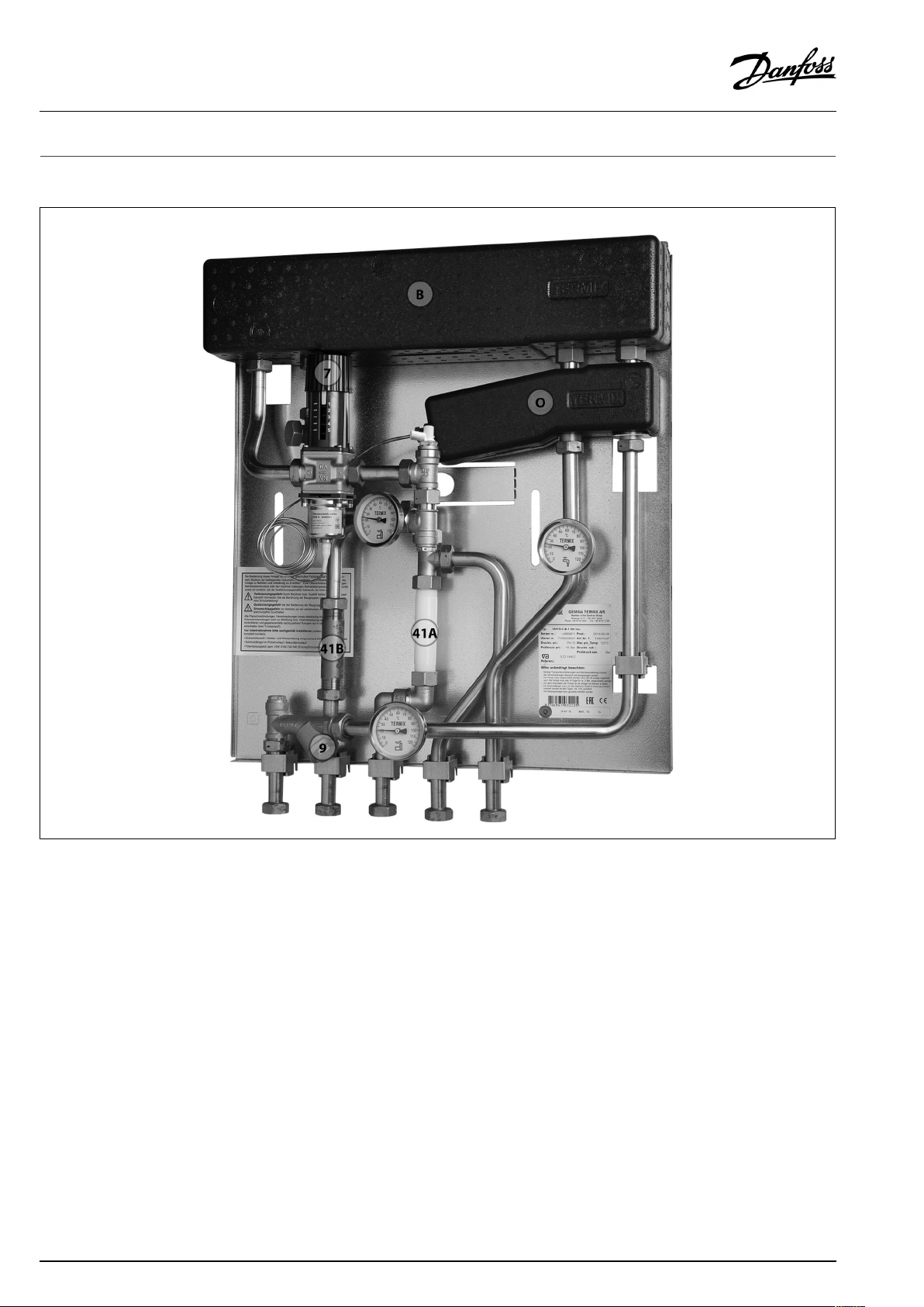
5.1Design
Yoursubstationmightlookdifferentthanthesubstationshown.
Designdescription
B
Heatexchanger,DHW
O
Termixsensoraccelerator
7
Thermostaticvalve,DHW
9
Strainer
41A
Fittingpiece,coldwatermains
41BFittingpiece,energymeter
8|©Danfoss|2019.04
VI.HE.S4.02/LUK40111
Page 9

OperatingGuideTermixVMTD-F-BOH
5.2Schematicdiagram
DHW
HWC
CWM
DCW
DH
Supply
DH
Return
Yoursubstationmightlookdifferentthantheschematicdiagramshown.
Schematicdescription
B
Heatexchanger,DHW
2
Singlecheckvalve
7
Thermostaticvalve,DHW
9
Strainer
11
Domestichotwaterpump
14
Sensorpocket,energymeter
DHW:DomesticHotWater
HWC:
CWM:
DCW:
DHSupply:DistrictHeatingSupply
DHReturn:DistrictHeatingReturn
5.2.1Technicalparameters
Technicalparameters
Nominalpressure:
Max.DHsupplytemperature:
Min.DCWstaticpressure:
Brazingmaterial(HEX):
Heatexchangerstestpressure:30bar
Soundlevel:≤55dB
HotWaterCirculation
ColdWaterMains
DomesticColdWater
18
Thermometer
21A
Optional
39
Connectionclosed
41A
Fittingpiece,coldwatermains
41BFittingpiece,energymeter
48
Airvent,manual
PN16
120°C
0.5bar
Copper
VI.HE.S4.02/LUK40111
©Danfoss|2019.04|9
Page 10

OperatingGuideTermixVMTD-F-BOH
6.0Controls
6.1DHWtemperaturecontrol
DHWtemperaturecontrol
TherearevarioustypesofDHWtemperaturecontrolusedin
Danfosssubstations.
DHWtemperatureshouldbeadjustedto45-50°C,asthisprovides
optimalutilisationofDHwater.AtDHWtemperaturesabove55°C,
thepossibilityoflimescaledepositsincreasessignificantly.
6.1.1AVTBcontroller(20–60°)
Thetemperaturesettingisasfollows:
1=20°C
2=35°C
3=50°C
4=60°C
5=70°C
Thevaluesareintendedasaguide.
TheAVTBoperatesatitsbestatDHsupplytemperaturesofupto
90°C.
Thermostaticcontrol
DHWtemperatureisadjustedasfollows:
Toincreasetemperature,turnthehandleonthethermostatic
controllertoselectahighernumber.
Todecreasetemperature,turnthehandleonthethermostatic
controllertoselectalowernumber.
10|©Danfoss|2019.04
VI.HE.S4.02/LUK40111
Page 11

OperatingGuideTermixVMTD-F-BOH
6.2Other
6.2.1Safetyvalve
Thepurposeofthesafetyvalveistoprotectthesubstationfrom
excessivepressure.
Theblow-offpipefromthesafetyvalvemustnotbeclosed.The
blow-offpipeoutletshouldbeplacedsothatitdischargesfreely
anditispossibletoobserveanydrippingfromthesafetyvalve.
Itisrecommendedtochecktheoperationofsafetyvalvesat
intervalsof6months.Thisisdonebyturningthevalveheadin
directionindicated.
6.2.2Strainer
Strainersshouldbecleanedregularlybyauthorizedpersonnel.The
frequencyofcleaningwoulddependonoperatingconditionsand
themanufacturer’sinstructions.
6.2.3GTUPressureEqualizer
TheGTUPressureEqualizerabsorbstheexpansiononthe
secondarysideoftheTermixwaterheatersandcanbeusedasa
substitutetothesafetyvalve.
Furthermorethepressureequalizerabsorbsapossibleincreasein
pressure,soadischargeoutletisomitted.
TheGTUPressureEqualizermaynotbeappliedinsystemswithhot
watercirculation.
VI.HE.S4.02/LUK40111
©Danfoss|2019.04|11
Page 12

OperatingGuideTermixVMTD-F-BOH
6.2.4Fittingpiece
Thesubstationisequippedwithafittingpieceforenergymeter.
Assemblyofenergymeters:
1:Closeballvalves
ClosetheballvalvesonDHSupplyandDHReturn,ifthereiswater
onthesystem.
2:Loosennuts
Loosenthenutsonthefittingpiece.
3:Removefittingpiece
Removethefittingpieceandreplaceitwiththeenergymeter.Do
notforgetthegaskets.
4:Tightenconnections
Aftermountingoftheenergymeterremembertocheckand
tightenallthreadedconnections.
Sensorpocket,energymeter
Thesensorsoftheenergymeterismountedinthesensorpockets.
12|©Danfoss|2019.04
VI.HE.S4.02/LUK40111
Page 13
OperatingGuideTermixVMTD-F-BOH
6.3Maintenance
Thesubstationrequireslittlemonitoring,apartfromroutine
checks.Itisrecommendedtoreadtheenergymeteratregular
intervals,andtowritedownthemeterreadings.
RegularinspectionsofthesubstationaccordingtothisInstruction
arerecommended,whichshouldinclude:
Strainers
Cleaningofstrainers.
Meters
Checkingofalloperatingparameterssuchasmeterreadings.
Temperatures
Checkingofalltemperatures,suchasDHsupplytemperatureand
DHWtemperature.
Connections
Checkingallconnectionsforleakages.
Safetyvalves
Theoperationofthesafetyvalvesshouldbecheckedbyturning
thevalveheadintheindicateddirection.
Venting
Checkingthatthesystemisthoroughlyvented.
Authorizedpersonnelonly
Assembly,start-upandmaintenanceworkmustbeperformedby
qualifiedandauthorizedpersonnelonly.
Inspectionsshouldbecarriedoutminimumeverytwoyears.
SparepartscanbeorderedfromDanfoss.Pleaseensurethatany
enquiryincludesthesubstationserialnumber.
VI.HE.S4.02/LUK40111
©Danfoss|2019.04|13
Page 14

OperatingGuideTermixVMTD-F-BOH
7.0Troubleshooting
7.1Troubleshootingingeneral
Intheeventofoperatingdisturbances,thefollowingbasicfeatures
shouldbecheckedbeforecarryingoutactualtroubleshooting:
•thesubstationisconnectedtoelectricity,
•thestrainerontheDHsupplypipeisclean,
•thesupplytemperatureoftheDHisatthenormallevel
(summer,atleast60°C-winter,atleast70°C),
•thedifferentialpressureisequaltoorhigherthanthenormal
(local)differentialpressureintheDHnetwork–ifindoubt,ask
theDHplantsupervisor,
•pressureonthesystem-checktheHEpressuregauge.
Authorizedpersonnelonly
Assembly,start-upandmaintenanceworkmustbeperformedby
qualifiedandauthorizedpersonnelonly.
14|©Danfoss|2019.04
VI.HE.S4.02/LUK40111
Page 15

OperatingGuideTermixVMTD-F-BOH
7.2TroubleshootingDHW
ProblemPossiblecauseSolution
ToolittleornoDHW.
Taptemperaturetoohigh;DHWtapload
toohigh.
Temperaturedropduringtapping.
Thermostaticcontrolvalvedoesnotclose
Strainerinsupplyorreturnlineclogged.Cleanstrainer(s).
DHWcirculationpumpoutoforderorwith
toolowsetting.
Defectiveorcloggednon-returnvalve.
Noelectricity.Check.
Wrongsettingofautomaticcontrols,ifany.Toadjustanelectroniccontrollerfor
Scalingoftheplateheatexchanger.
Defectivemotorizedvalve.Check(usemanualfunction)–replace.
Defectivetemperaturesensors.
Defectivecontroller.
DCWisbeingmixedwiththeDHW,e.g.ina
defectivethermostaticmixingvalve.
Defectiveorcloggednon-returnvalveon
circulationvalve.
Thermostaticvalveadjustedtoatoohigh
level.
Scalingoftheplateheatexchanger.
LargerDHWflowthanthesubstationhas
beendesignedfor.
TemperaturedifferencebetweenDH
supplyandDHWsetpointtoolow.
Checkcirculationpump.
Replace–clean.
DHW,pls.noteenclosedinstructionsfor
electroniccontroller.
Replace–rinseout.
Check–replace.
Check–replace.
Check–replace. Hotwaterinsometapsbutnotinall.
Replace–clean.
Check–set.
Replace–rinseout.
ReduceDHWflow.
Lowerthesetpointtemperatureorincrease
theDHsupplytemperature.
VI.HE.S4.02/LUK40111
©Danfoss|2019.04|15
Page 16

OperatingGuideTermixVMTD-F-BOH
7.3Disposal
Disposal
Thisproductshouldbedismantledanditscomponents
sorted,ifpossible,invariousgroupsbeforerecycling
ordisposal.
Alwaysfollowthelocaldisposalregulations.
16|©Danfoss|2019.04
VI.HE.S4.02/LUK40111
Page 17

OperatingGuideTermixVMTD-F-BOH
17|©Danfoss|2019.04
VI.HE.S4.02/LUK40111
Page 18

OperatingGuideTermixVMTD-F-BOH
8.0Declaration
8.1Declarationofconformity
Category0withoutelectricalequipment
18|©Danfoss|2019.04
VI.HE.S4.02/LUK40111
Page 19

OperatingGuideTermixVMTD-F-BOH
Category0withelectricalequipment
VI.HE.S4.02/LUK40111
©Danfoss|2019.04|19
Page 20

OperatingGuideTermixVMTD-F-BOH
20|©Danfoss|2019.04
VI.HE.S4.02/LUK40111
 Loading...