

Page 1

OperatingGuide
TermixVMTD-F-B
1.0TableofContents
1.0TableofContents.............................................1
........................................................................2
2.0Functionaldescription......................................3
3.0Safetynotes.....................................................4
3.1SafetyNotes–general............................................4
4.0Mounting........................................................5
4.1Mounting...........................................................5
4.2Start-up..............................................................6
4.3Electricalconnections.............................................7
5.0Design.............................................................8
5.1Design...............................................................8
5.2Schematicdiagram................................................9
6.0Controls..........................................................10
6.1Heatingcircuit......................................................10
6.2DHWtemperaturecontrol........................................11
6.3Other.................................................................11
6.4Maintenance........................................................14
7.0Troubleshooting..............................................15
7.1Troubleshootingingeneral......................................15
7.2TroubleshootingDHW............................................15
7.3TroubleshootingHE...............................................16
7.4Disposal.............................................................17
8.0Declaration......................................................18
8.1Declarationofconformity........................................18
DanfossDistrictEnergy
VI.CW.C4.02/LUK40110
DEN-GT
1
Page 2
OperatingGuideTermixVMTD-F-B
2
DEN-GT
VI.CW.C4.02/LUK40110
DanfossDistrictEnergy
Page 3
OperatingGuideTermixVMTD-F-B
2.0Functionaldescription
Districtheatingsubstationfordirectheatingand
instantaneousdomestichotwater .
Application
TheTermixVMTD-F-Bisacompletesolutionwithbuilt-inwater
heaterandadifferentialpressurecontrolledheatingsystem.Termix
VMTD-F-Bisapplicableforsingleandmulti-familyhousesandfor
decentralizedsystems.
Districtheating(DH)
Thesubstationisprefabricatedwithadifferentialpressure
controller,attingpieceandsensorpocketsforinsertionofaheat
meteraswellasstrainerandballvalves.
Heating(HE)
Theheatingcircuitisdesignedfordirectgenerationofheat.
Thedifferentialpressurecontrolsetstheoptimumoperation
conditionsforradiatorthermostaticvalvesinordertoenable
individualtemperaturecontrolineachroom.Inordertoenablea
time-dependingtemperaturecontrolprogram,azonevalvewith
actuatorandaroomthermostatcanbeincludedasanoption.
Domestichotwater(DHW)
Thedomestichotwaterispreparedintheheatexchangerandthe
temperatureisregulatedwithathermostaticcontrolvalve.The
patentedsensoracceleratoracceleratestheclosingoftheDanfoss
AVTBvalveandprotectstheheatexchangeragainstoverheating
andlimescaleformation.TheheatexchangercoolstheDHwater
veryefciently,therebycreatingaverygoodoperatingeconomy.
ThesensoracceleratorandAVTBvalvealsoworksasabypass
keepingthehousesupplylinewarm.Thisshortensthewaiting
periodsduringsummerwhentheheatingsystemisinreduced
operation.Thesensoracceleratorhelpstoensureastablehot
watertemperatureregardlessofvaryingloads,owtemperatures
anddifferentialpressurewithouttheneedforreadjustingthevalve.
DanfossDistrictEnergy
VI.CW.C4.02/LUK40110
DEN-GT
3
Page 4
OperatingGuideTermixVMTD-F-B
3.0Safetynotes
3.1SafetyNotes–general
Thefollowinginstructionsrefertothestandarddesignof
substation.Specialversionsofsubstationsareavailableon
request.
Thisoperatingmanualshouldbereadcarefullybeforeinstallation
andstart-upofthesubstation.Themanufactureracceptsno
liabilityfordamageorfaultsthatresultfromnon-compliancewith
theoperatingmanual.Pleasereadandfollowalltheinstructions
carefullytopreventaccidents,injuryanddamagetoproperty.
Assembly,start-upandmaintenanceworkmustbeperformedby
qualiedandauthorizedpersonnelonly.
Pleasecomplywiththeinstructionsissuedbythesystem
manufacturerorsystemoperator.
Corrosionprotection
Allpipesandcomponentsaremadeofstainlesssteelandbrass.
Themaximumchloridecompoundsoftheowmediumshouldnot
behigherthan150mg/l.
Theriskofequipmentcorrosionincreasesconsiderablyifthe
recommendedlevelofpermissiblechloridecompoundsis
exceeded.
Energysource
Thesubstationisdesignedfordistrictheatingastheprimary
sourceofenergy.However,alsootherenergysourcescanbeused
wheretheoperatingconditionsallowitandalwaysarecomparable
todistrictheating.
Application
Thesubstationisdesignedtobeconnectedtothehouse
installationinafrost-freeroom,wherethetemperaturedoesnot
exceed50°Candthehumiditydoesnotexceed60%.Donotcover
orwallupthesubstationorinanyotherwayblocktheentrance
tothestation.
Authorizedpersonnelonly
Assembly,start-upandmaintenanceworkmustbeperformedby
qualiedandauthorizedpersonnelonly.
Pleaseobserveinstructionscarefully
Toavoidinjurytopersonsanddamagetothedevice,itisabsolutely
necessarytoreadandobservetheseinstructionscarefully.
Warningofhighpressureandtemperature
Beawareoftheinstallation’spermissiblesystempressureand
temperature.
Themaximumtemperatureoftheowmediuminthesubstationis
120°C.
Themaximumoperatingpressureofthesubstationis10bar .PN16
versionsareavailableonenquiry.
Theriskofpersonsbeinginjuredandequipmentdamagedincreases
considerablyiftherecommendedpermissibleoperatingparameters
areexceeded.
Thesubstationinstallationmustbeequippedwithsafetyvalves,
however,alwaysinaccordancewithlocalregulations.
Choiceofmaterial
Choiceofmaterialsalwaysincompliancewithlocallegislation.
Safetyvalve(s)
Werecommendmountingofsafetyvalve(s),however,alwaysin
compliancewithlocalregulations.
Connection
Thesubstationmustbeequippedwithfeaturesthatensurethat
thesubstationcanbeseparatedfromallenergysources(also
powersupply).
Emergency
Incaseofdangeroraccidents-re,leaksorotherdangerous
circumstances-interruptallenergysourcestothestationif
possible,andseekexperthelp.
Incaseofdiscolouredorbad-smellingdomestichotwater,closeall
shut-offvalvesonthesubstation,informtheoperatingpersonnel
andcallforexperthelpimmediately.
Storage
Anystorageofthesubstationwhichmaybenecessarypriorto
installationshouldbeinconditionswhicharedryandheated.
Warningofhotsurface
Thesubstationhasgothotsurfaces,whichcancauseskinburns.
Pleasebeextremelycautiousincloseproximitytothesubstation.
Powerfailurecanresultinthemotorvalvesbeingstuckinopen
position.Thesurfacesofthesubstationcangethot,whichcancause
skinburns.Theballvalvesondistrictheatingsupplyandreturnshould
beclosed.
Warningoftransportdamage
Beforesubstationinstallation,pleasemakesurethatthesubstation
hasnotbeendamagedduringtransport.
IMPORTANT-Tighteningofconnections
Duetovibrationsduringtransportallangeconnections,screwjoints
andelectricalclampandscrewconnectionsmustbecheckedand
tightenedbeforewaterisaddedtothesystem.Afterwaterhasbeen
addedtothesystemandthesystemhasbeenputintooperation,
re-tightenALLconnections.
4
DEN-GT
VI.CW.C4.02/LUK40110
DanfossDistrictEnergy
Page 5
OperatingGuideTermixVMTD-F-B
4.0Mounting
4.1Mounting
Installationmustbeincompliancewithlocalstandardsand
regulations.
Districtheating(DH)-Inthefollowingsections,DHreferstothe
heatsourcewhichsuppliesthesubstations.Avarietyofenergy
sources,suchasoil,gasorsolarpower,couldbeusedasthe
primarysupplytoDanfosssubstations.Forthesakeofsimplicity,
DHcanbetakentomeantheprimarysupply.
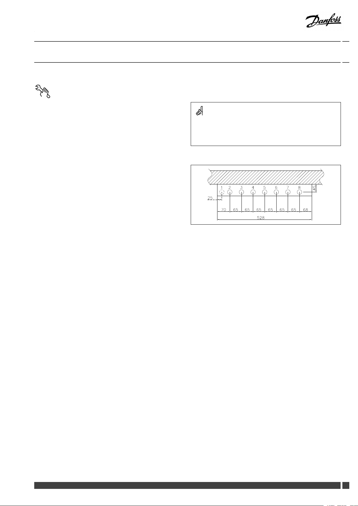
Connections:
1.Hotwatercirculation(HWC)(Optional)
2.Districtheating(DH)supply
3.Districtheating(DH)return
4.Coldwatermains(CWM)
5.Domesticcoldwater(DCW)
6.Domestichotwater(DHW)
7.Heating(HE)supply
8.Heating(HE)return
Authorizedpersonnelonly
Assembly,start-upandmaintenanceworkmustbeperformedby
qualiedandauthorizedpersonnelonly.
Thepipeplacementcandeviatefromtheshowndrawing.Pleasenote
themarkingsonthestation.
Connectionsizes:
DH+HE:
CWM+DCW+DHW:
G¾”(int.thread)
G¾”(int.thread)
Dimensions(mm):
Withoutcover:
H710xW528xD150
Withcover(mountonwallvariant):
H800xW540xD190
Withcover(built-inwallvariant):
H915–980xW610xD150
Weight(approx.):20kg
DanfossDistrictEnergy
VI.CW.C4.02/LUK40110
DEN-GT
5
Page 6
OperatingGuideTermixVMTD-F-B
4.1.1Installation
Mounting:
Adequatespace
Pleaseallowadequatespacearoundthesubstationformounting
andmaintenancepurposes.
Orientation
Thestationmustbemountedsothatcomponents,keyholes
andlabelsareplacedcorrectly.Ifyouwishtomountthestation
differentlypleasecontactyoursupplier.
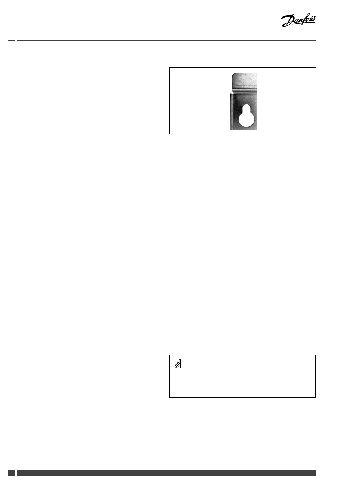
Drillings
Wheresubstationsaretobewall-mounted,drillingsareprovided
inthebackmountingplate.Floormountedunitshavesupport.
Labelling
Eachconnectiononthesubstationislabelled.
Beforeinstallation:
Cleanandrinse
Priortoinstallation,allsubstationpipesandconnectionsshouldbe
cleanedandrinsed.
Keyholeformounting.
Tightening
Duetovibrationduringtransport,allsubstationconnectionsmust
becheckedandtightenedbeforeinstallation.
Unusedconnections
Unusedconnectionsandshut-offvalvesmustbesealedwitha
plug.Shouldtheplugsrequireremoval,thismustonlybedoneby
anauthorizedservicetechnician.
Installation:
Strainer
Ifastrainerissuppliedwiththestationitmustbettedaccording
toschematicdiagram.Pleasenotethatthestrainermaybe
suppliedloose.
Connections
Internalinstallationanddistrictheatingpipesconnectionsmustbe
madeusingthreaded,angedorweldedconnections.
4.2Start-up
Start-up,Directheating
Theshut-offvalvesshouldbeopenedandtheunitobservedas
itentersservice.Visualcheckingshouldconrmtemperatures,
pressures,acceptablethermalexpansionandabsenceofleakage.
Iftheheatexchangeroperatesinaccordancewithdesign,itcanbe
puttoregularuse.
Re-thightenconnections
Afterwaterhasbeenaddedtothesystemandthesystemhasbeen
putintooperation,re-tightenALLconnections.
Afterwaterhasbeenaddedtothesystemandthesystemhasbeen
putintooperation,re-tightenALLconnections.
6
DEN-GT
VI.CW.C4.02/LUK40110
DanfossDistrictEnergy
Page 7

OperatingGuideTermixVMTD-F-B
4.3Electricalconnections
Beforemakingelectricalconnections,pleasenotethe
following:
Safetynotes
Pleasereadtherelevantpartsofthesafetynotes.
230V
Thesubstationmustbeconnectedto230VACandearth.
Potentialbonding
Potentialbondingshouldbecarriedoutaccording
to60364-4-41:2007andIEC60364-5-54:2011.
Bondingpointonthemountingplatebelowrightcornermarked
withearthsymbol.
Disconnection
Thesubstationmustbeelectricallyconnectedsothatitcanbe
disconnectedforrepairs.
Outdoortemperaturesensor
Outdoorsensorsshouldbemountedsoastoavoidexposureto
directsunlight.Theyshouldnotbeplacedclosetodoors,windows
orventilationoutlets.
Theoutdoorsensormustbeconnectedtothestationonthe
terminalblockundertheelectroniccontrol.
Authorizedelectrician
Electricalconnectionsmustbemadebyanauthorizedelectricianonly.
Localstandards
Electricalconnectionsmustbemadeinaccordancewithcurrent
regulationsandlocalstandards.
DanfossDistrictEnergy
VI.CW.C4.02/LUK40110
DEN-GT
7
Page 8

OperatingGuideTermixVMTD-F-B
5.0Design
5.1Design
Yoursubstationmightlookdifferentthanthesubstationshown.
Designdescription
B
Heatexchanger,DHW
O
Termixsensoraccelerator
7
Thermostaticvalve,DHW
9
Strainer41BFittingpiece,energymeter
8
DEN-GT
14
Sensorpocket,energymeter
31
Differentialpressurecontroller
41A
Fittingpiece,coldwatermains
VI.CW.C4.02/LUK40110
DanfossDistrictEnergy
Page 9

OperatingGuideTermixVMTD-F-B
5.2Schematicdiagram
DHW
CWM
DCW
DH
Supply
DH
Return
Yoursubstationmightlookdifferentthantheschematicdiagramshown.
Schematicdescription
B
Heatexchanger,DHW
7
Thermostaticvalve,DHW
9
Strainer41BFittingpiece,energymeter
14
Sensorpocket,energymeter
31
Differentialpressurecontroller
41A
Fittingpiece,coldwatermains
DHW:DomesticHotWater
CWM:
DCW:
ColdWaterMains
DomesticColdWater
DHSupply:DistrictHeatingSupply
DHReturn:DistrictHeatingReturn
HESupply:HeatingSupply
HEReturn:HeatingReturn
HE
Supply
HE
Return
5.2.1Technicalparameters
Technicalparameters
Nominalpressure:PN10(PN16versionsareavailableonenquiry)
Max.DHsupplytemperature:
Min.DCWstaticpressure:
Brazingmaterial(HEX):
120°C
0.5bar
Copper
Heatexchangerstestpressure:30bar
Soundlevel:≤55dB
DanfossDistrictEnergy
VI.CW.C4.02/LUK40110
DEN-GT
9
Page 10

OperatingGuideTermixVMTD-F-B
6.0Controls
6.1Heatingcircuit
6.1.1Differentialpressurecontroller
Thedifferentialpressurecontrollersmoothsouttheuctuationsin
pressurearrivingfromthedistrictheatingnetwork.Theoperating
pressureinthesubstationisthusheldsteady.
6.1.2TP7000
TP7000electronic7dayprogrammableroomthermostat.
Signalsfromtheroomthermostatcanbeusedtocontrolzone
valves.
10
DEN-GT
VI.CW.C4.02/LUK40110
DanfossDistrictEnergy
Page 11

OperatingGuideTermixVMTD-F-B
6.2DHWtemperaturecontrol
DHWtemperaturecontrol
TherearevarioustypesofDHWtemperaturecontrolusedin
Danfosssubstations.
DHWtemperatureshouldbeadjustedto45-50°C,asthisprovides
optimalutilisationofDHwater.AtDHWtemperaturesabove55°C,
thepossibilityoflimescaledepositsincreasessignicantly.
6.2.1AVTBcontroller(20–60°)
Thetemperaturesettingisasfollows:
1=20°C
2=35°C
3=50°C
4=60°C
5=70°C
Thevaluesareintendedasaguide.
TheAVTBoperatesatitsbestatDHsupplytemperaturesofupto
90°C.
Thermostaticcontrol
DHWtemperatureisadjustedasfollows:
Toincreasetemperature,turnthehandleonthethermostatic
controllertoselectahighernumber.
Todecreasetemperature,turnthehandleonthethermostatic
controllertoselectalowernumber.
6.3Other
6.3.1Safetyvalve
Thepurposeofthesafetyvalveistoprotectthesubstationfrom
excessivepressure.
Theblow-offpipefromthesafetyvalvemustnotbeclosed.The
blow-offpipeoutletshouldbeplacedsothatitdischargesfreely
anditispossibletoobserveanydrippingfromthesafetyvalve.
Itisrecommendedtochecktheoperationofsafetyvalvesat
intervalsof6months.Thisisdonebyturningthevalveheadin
directionindicated.
DanfossDistrictEnergy
VI.CW.C4.02/LUK40110
DEN-GT
11
Page 12

OperatingGuideTermixVMTD-F-B
6.3.2Strainer
Strainersshouldbecleanedregularlybyauthorizedpersonnel.The
frequencyofcleaningwoulddependonoperatingconditionsand
themanufacturer’sinstructions.
6.3.3GTUPressureEqualizer
TheGTUPressureEqualizerabsorbstheexpansiononthe
secondarysideoftheTermixwaterheatersandcanbeusedasa
substitutetothesafetyvalve.
Furthermorethepressureequalizerabsorbsapossibleincreasein
pressure,soadischargeoutletisomitted.
TheGTUPressureEqualizermaynotbeappliedinsystemswithhot
watercirculation.
6.3.4ReturntemperaturelimiterFJVR(10-80°C)
ThereturnlimitertypeFJVRautomaticallycontrolsthereturn
temperaturefromradiators,convectorsandunderoorheating
pipes.
12
DEN-GT
VI.CW.C4.02/LUK40110
DanfossDistrictEnergy
Page 13

OperatingGuideTermixVMTD-F-B
6.3.5Fittingpiece
Thesubstationisequippedwithattingpieceforenergymeter.
Assemblyofenergymeters:
1:Closeballvalves
ClosetheballvalvesonDHSupplyandDHReturn,ifthereiswater
onthesystem.
2:Loosennuts
Loosenthenutsonthettingpiece.
3:Removettingpiece
Removethettingpieceandreplaceitwiththeenergymeter.Do
notforgetthegaskets.
4:Tightenconnections
Aftermountingoftheenergymeterremembertocheckand
tightenallthreadedconnections.
Sensorpocket,energymeter
Thesensorsoftheenergymeterismountedinthesensorpockets.
DanfossDistrictEnergy
VI.CW.C4.02/LUK40110
DEN-GT
13
Page 14

OperatingGuideTermixVMTD-F-B
6.4Maintenance
Thesubstationrequireslittlemonitoring,apartfromroutine
checks.Itisrecommendedtoreadtheenergymeteratregular
intervals,andtowritedownthemeterreadings.
RegularinspectionsofthesubstationaccordingtothisInstruction
arerecommended,whichshouldinclude:
Strainers
Cleaningofstrainers.
Meters
Checkingofalloperatingparameterssuchasmeterreadings.
Temperatures
Checkingofalltemperatures,suchasDHsupplytemperatureand
DHWtemperature.
Connections
Checkingallconnectionsforleakages.
Safetyvalves
Theoperationofthesafetyvalvesshouldbecheckedbyturning
thevalveheadintheindicateddirection.
Authorizedpersonnelonly
Assembly,start-upandmaintenanceworkmustbeperformedby
qualiedandauthorizedpersonnelonly.
Venting
Checkingthatthesystemisthoroughlyvented.
Inspectionsshouldbecarriedoutminimumeverytwoyears.
SparepartscanbeorderedfromDanfoss.Pleaseensurethatany
enquiryincludesthesubstationserialnumber.
14
DEN-GT
VI.CW.C4.02/LUK40110
DanfossDistrictEnergy
Page 15

OperatingGuideTermixVMTD-F-B
7.0Troubleshooting
7.1Troubleshootingingeneral
Intheeventofoperatingdisturbances,thefollowingbasicfeatures
shouldbecheckedbeforecarryingoutactualtroubleshooting:
•thesubstationisconnectedtoelectricity,
•thestrainerontheDHsupplypipeisclean,
•thesupplytemperatureoftheDHisatthenormallevel
(summer,atleast60°C-winter,atleast70°C),
•thedifferentialpressureisequaltoorhigherthanthenormal
(local)differentialpressureintheDHnetwork–ifindoubt,ask
theDHplantsupervisor,
•pressureonthesystem-checktheHEpressuregauge.
7.2TroubleshootingDHW
Authorizedpersonnelonly
Assembly,start-upandmaintenanceworkmustbeperformedby
qualiedandauthorizedpersonnelonly.
ProblemPossiblecauseSolution
ToolittleornoDHW.
Strainerinsupplyorreturnlineclogged.Cleanstrainer(s).
DHWcirculationpumpoutoforderorwith
toolowsetting.
Defectiveorcloggednon-returnvalve.
Noelectricity.Check.
Wrongsettingofautomaticcontrols,ifany.Toadjustanelectroniccontrollerfor
Scalingoftheplateheatexchanger.
Defectivemotorizedvalve.Check(usemanualfunction)–replace.
Defectivetemperaturesensors.
Defectivecontroller.
DCWisbeingmixedwiththeDHW,e.g.in
adefectivethermostaticmixingvalve.
Defectiveorcloggednon-returnvalveon
circulationvalve.
Taptemperaturetoohigh;DHWtapload
toohigh.
Thermostaticvalveadjustedtoatoohigh
level.
Scalingoftheplateheatexchanger.
LargerDHWowthanthesubstationhas
beendesignedfor.
Thermostaticcontrolvalvedoesnotclose
TemperaturedifferencebetweenDH
supplyandDHWsetpointtoolow.
Checkcirculationpump.
Replace–clean.
DHW,pls.noteenclosedinstructionsfor
electroniccontroller.
Replace–rinseout.
Check–replace.
Check–replace.
Check–replace. Hotwaterinsometapsbutnotinall.
Replace–clean.
Check–set.
Replace–rinseout. Temperaturedropduringtapping.
ReduceDHWow.
Lowerthesetpointtemperatureor
increasetheDHsupplytemperature.
DanfossDistrictEnergy
VI.CW.C4.02/LUK40110
DEN-GT
15
Page 16

OperatingGuideTermixVMTD-F-B
7.3TroubleshootingHE
ProblemPossiblecauseSolution
Toolittleornoheat.StrainercloggedinDHorHEcircuit
(radiatorcircuit).
ThelterintheenergymeteronDHcircuit
clogged.
Defectiveorwronglyadjusteddifferential
pressurecontroller.
Sensordefective–orpossiblydirtinthe
valvehousing.
Automaticcontrols,ifany,wronglysetor
defective-possiblypowerfailure.
Pumpoutofoperation.Checkifthepumpisreceivingpowerand
Thepumpissetattoolowspeedof
rotation.
Pressuredrop–thepressuredropon
theradiatorcircuitshowslowerthan
recommendedoperatingpressure.
Airpocketsinthesystem.Venttheinstallationthoroughly.
Limitingofthereturntemperature
adjustedtoolow.
Defectiveradiatorvalves.
Unevenheatdistributioninbuilding
becauseofincorrectlysetbalancingvalves,
orbecausetherearenobalancingvalves.
Diameterofpipetosubstationtoosmallor
branchpipetoolong.
Unevenheatdistribution.Airpocketsinthesystem.Venttheinstallationthoroughly.
DHsupplytemperaturetoohigh.
Wrongsettingofthermostatorof
automaticcontrols,ifany.
Defectivecontroller.Thecontrollerdoes
notreactasitshouldaccordingtothe
instructions.
Defectivesensoronself-actingthermostat.
DHsupplytemperaturetoolow.
Wrongsettingofautomaticcontrols,ifany.
Defectivecontroller.Thecontrollerdoes
notreactasitshouldaccordingtothe
instructions.
Defectivesensoronself-actingthermostat.
Wrongplacement/ttingofoutdoor
temperaturesensor.
Strainerclogged.Cleangate/strainer.
Cleangate/strainer(s).
Cleanthelter(afterconsultingtheDH
plantoperator).
Checktheoperationofthedifferential
pressurecontroller–cleanthevalveseatif
required.
Checktheoperationofthethermostat–
cleanthevalveseatifrequired.
Checkifthesettingofthecontroller
iscorrect–seeseparateinstructions.
Checkthepowersupply.Temporary
settingofmotorto“manual”control–see
instructionsonautomaticcontrols.
thatitturns.Checkifthereisairtrappedin
thepumphousing–seepumpmanual.
Setthepumpathigherspeedofrotation.
Fillwateronthesystemandcheckthe
functioningofthepressureexpansion
vesselifrequired.
Adjustaccordingtoinstructions.
Check–replace.
Adjust/installbalancingvalves.
Checkpipedimensions.
Adjustautomaticcontrols,–see
instructionsforautomaticcontrols.
Callautomaticcontrolsmanufactureror
replacetheregulator.
Replacethermostat–orsensoronly.
Adjustautomaticcontrols–seeinstructions
forautomaticcontrols.
Callinautomaticcontrolsmanufactureror
replacecontroller.
Replacethermostat–orsensoronly.
Adjustlocationofoutdoortemperature
sensor.
16
DEN-GT
VI.CW.C4.02/LUK40110
DanfossDistrictEnergy
Page 17

OperatingGuideTermixVMTD-F-B
ToohighDHreturntemperature.
Noiseinsystem.
Heatloadtoohigh.
Toosmallheatingsurface/toosmall
Increasetotalheatingsurface.
radiatorscomparedtothetotalheating
requirementofthebuilding.
Poorutilizationofexistingheatingsurface.
Defectivesensoronself-actingthermostat.
Makesuretheheatisdistributedevenly
acrossthefullheatingsurface–openall
radiatorsandkeeptheradiatorsinthe
systemfromheatingupatthebottom.It
isextremelyimportanttokeepthesupply
temperaturetotheradiatorsaslowas
possible,whilemaintainingareasonable
levelofcomfort.
Thesystemissinglepipeloop.
Thesystemshouldfeatureelectronic
controlsaswellasreturnsensors.
Pumppressuretoohigh.Adjustpumptoalowerlevel.
Airinsystem.
Defectiveorincorrectlysetradiator
Ventthesystem.
Check–set/replace.
valve(s).Singlepipeloopsystemsrequire
specialone-piperadiatorvalves.
Dirtinthemotorizedvalveorinthe
Check–cleanout.
differentialpressurecontroller.
Defectivemotorizedvalve,sensoror
Check–replace.
automaticcontroller.
Electroniccontrollernotadjustedcorrectly.Adjustaccordingtoinstructions.
Pumppressuretoohigh.Adjustpumptoalowerlevel.
Defectivemotorizedvalve,sensoror
Check–replace.
electroniccontroller.
7.4Disposal
Disposal
Thisproductshouldbedismantledanditscomponents
sorted,ifpossible,invariousgroupsbeforerecycling
ordisposal.
Alwaysfollowthelocaldisposalregulations.
DanfossDistrictEnergy
VI.CW.C4.02/LUK40110
DEN-GT
17
Page 18

OperatingGuideTermixVMTD-F-B
8.0Declaration
8.1Declarationofconformity
Category0withoutelectricalequipment
18
DEN-GT
VI.CW.C4.02/LUK40110
DanfossDistrictEnergy
Page 19

OperatingGuideTermixVMTD-F-B
Category0withelectricalequipment
DanfossDistrictEnergy
VI.CW.C4.02/LUK40110
DEN-GT
19
Page 20

OperatingGuideTermixVMTD-F-B
ProducedbyDanfossA/S©11/2016
 Loading...