

Page 1
Datasheet
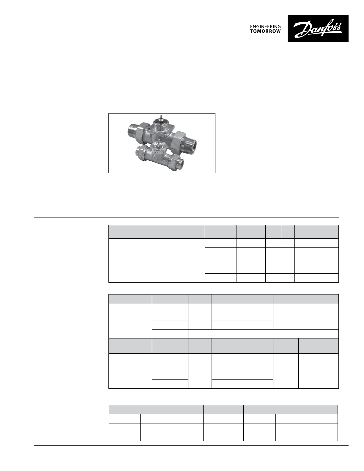
VMT
2-way water valve
Application:
Ordering
Information:
The VMT is a 2-way valve used in controlling the
flow of hot water within heating applications.
The VMT valve can be installed in applications
involving heating or chilled coils, hot water
storage tanks, plate heat exchangers or floor
heating systems. In the control of the VMT
valve, a thermostatic operator type RAVK or
a 24VAC electric actuator type TWA-V or ABV
can be mounted to the valve to regulate the
Features:
• Seated globe valve
• Brass body
• Low and high flow capacities
temperature and flow through the valve. The
VMT valves are available in ½”, ¾”, and 1” sizes
and the double union connections are available
in female sweat unions for ½” and ¾” and male
NPT connections for 1”.
• Double union tail piece connections
VMT Valves Code No. Model Size Cv Connection
w/ Union Connections
w/ Union Connections (High Capacity)
065F0102 VMT 15/8 1/2” 1.6 F. Sweat Unions
065F0104 VMT 20/8 3/4” 2.7 F. Sweat Unions
065F8960 VMT 15/2 1/2” 3.3 F. Sweat Unions
065F8961 VMT 20/2 3/4” 5.9 F. Sweat Unions
065F1242 VMT 25/2 1” 9.4 M. NPT Unions
AI000086448983
Suitable Controls for VMT
Typ e Code No. Model Setting Range Capillary Tube Length
003L3530
Thermostatic
Operator
Typ e Code No. Model Valve Function
Electric
Actuator
1. Direct rep lacement for RAV V. See cross referenc e chart below. 2. T WA-V should only to be u sed with VMT 15/8 and VMT 20/8 valv es.
Cross Reference Chart
RAV V >> RAVK
013U1251 104° - 158°F (40° - 70°C) >> 003L3531 95° - 167°F (35° - 75°C)
013U1252 80° - 132°F (27° - 57°C) >> 013U8063 77° - 149°F (25° - 65°C)
013U1255 50° - 100°F (10° - 38°C) >> 003L3530 50° - 86°F (10° - 30°C)
003L3531 95° to 167°F (35° to 75°C)
017- 4370 1/2” Brass Sensor Well for RAVK
088H3120
088H3121 Normally open
082F0052
082F0002 Normally open
RAVK
TWA-V
ABV
50° to 86°F (10° to 30°C)
Normally closed
Normally closed
6 ft. 6 in. (2 m)013U 8063 77° to 149°F (25° to 65°C)
Supply
Voltage
24 VAC
Power
Consumption
2.0 VA
9.0 VA
© Danfoss | 05/2020 | 1
Page 2
VMT 2-Way Water Valve Datasheet
Ordering
Information (Cont.):
Specifications:
Spare Parts
Code No. Typ e Size
013U0496
013U 0499 3/4”
Union Nut (Order two pieces per valve)
1/2”
013U0501 1”
013U0476
013U 0479 3/4”
Male NPT Tailpiece (Order two pieces per valve)
1/2”
013U 0489 1”
013U8608
013U 8609 3/4”
Female Sweat Tailpiece (Order two pieces per valve)
1/2”
013U 0 070 Packing Gland
Maximum test pressure 232 psi (16 bar)
Maximum working pressure 145 psi (10 bar)
Maximum flow temperature 250°F (12 0 °C)
Maximum differential pressure
(for quiet operation)
VMT 15/8 & 20/8: 12 psi (0.8 bar)
VMT 15/2, 20/2 & 25/2: 3 psi (0.2 bar)
Allowable fluid Water (maximum 30% glycol) in a closed loop hydronic
system.
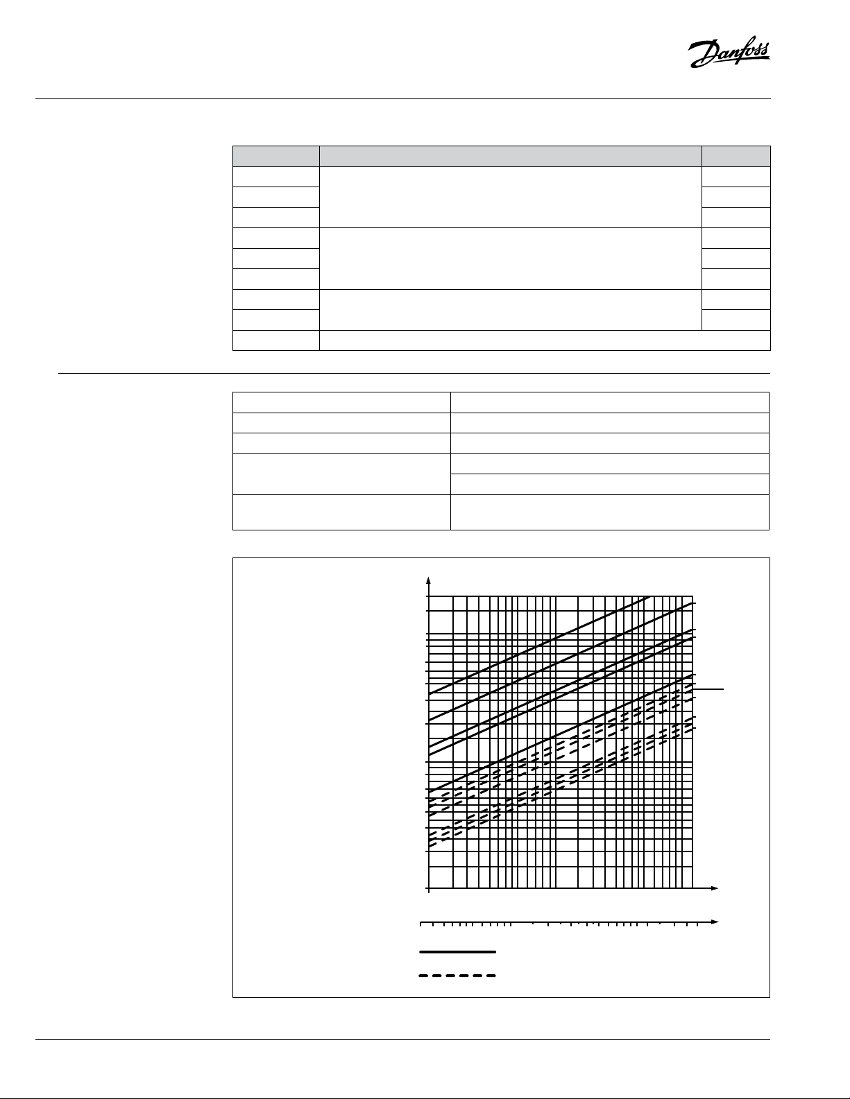
VMT Sizing Chart
Flow
US
GPM
VMT
20
10
8
6
5
4
3
2
1
0.8
0.6
0.5
0.4
0.3
0.2
0.1
0.1
0.510.30.2
0.50.7
0.30.2
0.7
Solid lines: Fully open valves
Dashed lines: Flow at 4°F P-deviation with RAVK
12345710
Pressure drop
2345 7102030
25/2
20/2
25/8
15/2 - 20/8
15/8
25/2
15/2
25/8
15/8
PSI
Feet WG
20/2
20/8
2 | © Danfoss | 05/2020
AI000086448983
Page 3

VMT 2-Way Water Valve Datasheet
Typical Installations:
Installation:
Hot water storage tank
Radiant system with electronic actuator
Floor heating system
Heat exchanger control
The valve body must be installed in the direction
of the flow as noted by the cast-in arrow located
on the body of the valve. Failure to install the
valve in the proper flow direction may result in
system noise during operation.
Construction:
AI000086448983
1
2
3
4
5
6
7
1 Pressure pin Stainless steel
2 Packing gland
3 O-ring EPDM rubber
4 Valve body Brass
5 Valve cone NBR rubber
6 Union nut Brass
7 Tailpiece Brass
© Danfoss | 05/2020 | 3
Page 4
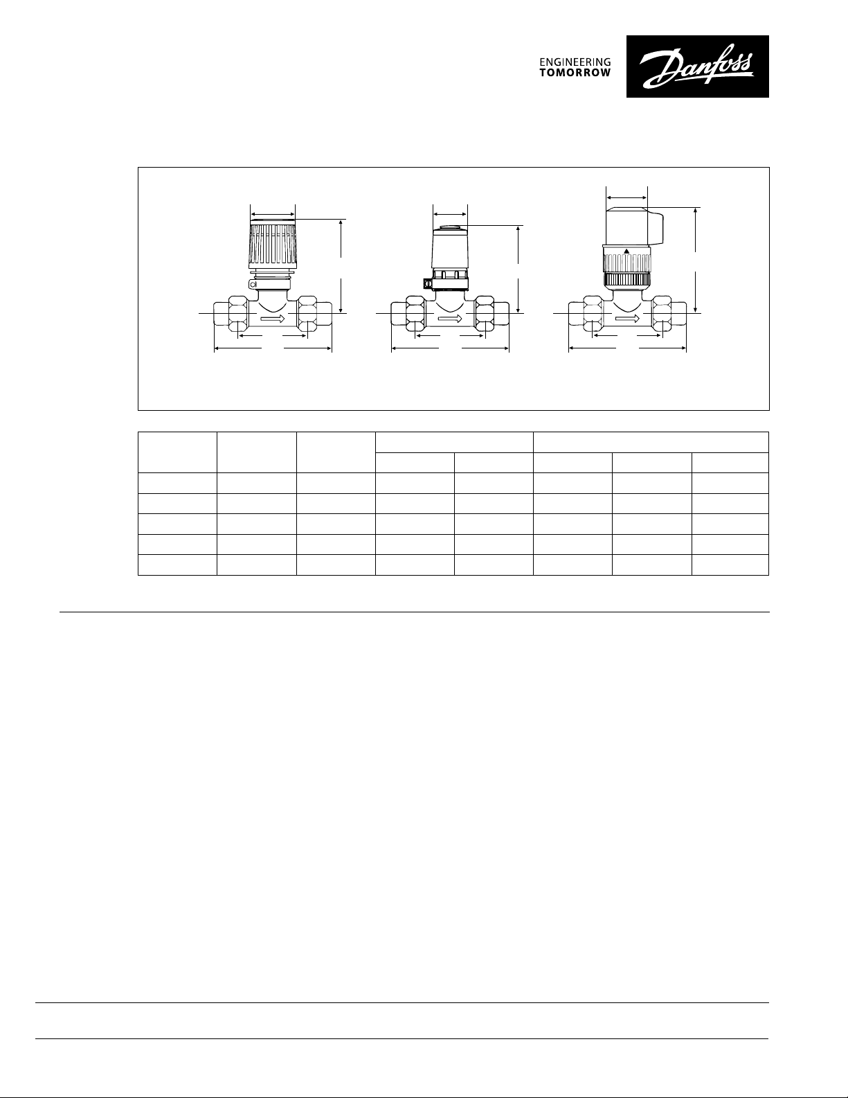
Dimensions:
mm
inches
61 41
2.4”
1.6”
50
1.97”
Size Type L1 in (mm)
1/2” VMT 15/8 2.6” (66) 3.9” (99) 5.1” (13 0) 4.1”(104) 3 . 6” (91) 4. 4” (112)
3/4” VMT 20/8 2.9” (74) 4.6” (117) 5.7” (145) 4.1” (104) 3.6” (91) 4.4 ” (112)
1/2” VMT 15/2 2.6” (66) 3.9” (99) 5.1” (13 0) 4.3” (109) - 4. 5” (114)
3/4” VMT 20/2 2.9” (74) 4.6” (117) 5. 4” (137) 4. 5” (114 ) - 4.6” (117)
*TWA-V should only be used with VMT 15/8 and VMT 20/8 valves
Typical Specification:
H
L
1
L
2
L
1
L
2
H
L
1
L
2
H
VMT with RAVK actuator VMT with TWA-V actuator VMT with ABV actuator
L2, in (mm) H, in (mm), VMT + control
F. s older M. NPT RAVK TWA-V* ABV
1” VMT 25/2 3. 6” (91) - 6.5” (165) 4. 7 ” (119 ) - 4.9” (124)
The 2-way mixing valve shall be a brass
construction with double union connections
for hot water heating applications. The valve
shall have a stamped indicator to reflect
proper piping of valve within system. The valve
replaceable. The regulation of the valve shall
be by means of thermostatic operator or 24VAC
electronic actuator. The actuators mounted
onto the valve shall be interchangeable. The
2-way water valve shall be a VMT series.
shall have a serviceable packing gland that is
Danfoss . Heating North America
Learn more at: www.heating.danfoss.us
Danfoss can accept no responsibility for possible errors in printed materials and reser ves the right to alter its products without notice.
All trademarks in this material are proper ty of the respective companies. Danfoss and Danfoss logotype are trademark s of Danfoss A/S. All rights reser ved.
4 | © Danfoss | 05/2020
AI000086448983
 Loading...