

Data sheet
Pressure balanced valves (PN 25)
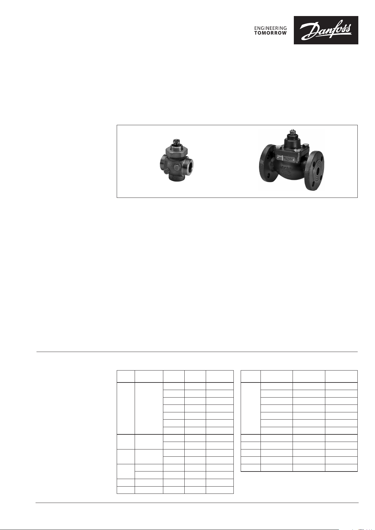
VM 2 – 2-way valve, external thread
VB 2 – 2-way valve, ange
Description
VM 2 VB 2
Ordering
Example:
2-way valve VM 2; DN 15; kVS 1,6;
PN 25; t
- 1× VM 2 DN 15 valve
Option:
- 1× Tailpieces
Code No.: 003H6908
150 °C; ext. thread
max
Code No.: 06 5B2014
VM 2 and VB 2 are two-way valves designed to
work with Danfoss electric actuators AMV(E)10,
AMV(E) 20, AMV(E) 30 or Danfoss electric
actuators with spring return function AMV(E) 13,
AMV(E) 23 and AMV(E) 33.
These VM 2 and VB 2 valves are generally
recommended for use in most demanding
conditions in systems such as:
- district heating,
- heating
- hot water service with heat exchanger or
storage tank where they ensure long and
unproblematic performance.
Features:
• SPLIT characteristic developed for most
demanding applications
• High closing p with small sized actuators
• Several kVS values
VM 2 (ext. thread)
Ext. thread k
DN
ISO 228/1 (m3/h) (mm)
15 G ¾ A
20 G 1 A
25 G 1¼ A
G 1½ A 10 7 065 B2018
32
G 1⁄ A 10 7 065B2029
40 G 2 A 16 10 065 B2019
50 G 2½ A 25 10 065B2020
Stroke
VS
0,25 5 065 B2010
0,4 5 0 65B 2011
0,63 5 06 5B2012
1,0 5 06 5B2013
1,6 5 06 5B2014
2,5 5 06 5B2015
4,0 5 065B2026
4,0 5 065 B2016
6,3 7 065B2027
6,3 5 06 5B20 17
8,0 5 065B2028
Code No.
• Push connection for easy mechanical
connection with actuator
• Control range min. 50:1
Benefits:
• Fast and stable regulation
• More comfort due to stable DHW temp.
• Energy saving due to stable control
• Longer lifetime of components due to less
temperature oscillation
Main data:
• DN 15-50
• kVS 0,25-40 m3/h
• PN 25
• Temperature:
- Circulation water/glycolic water up to 30 %:
2 … 150 °C
• Connections:
- External thread
- Flange
VB 2 (flange)
1)
k
DN
15
20 6,3 5 065B2057
25 10 7 065B2058
32 16 10 065B2059
40 25 10 065B2060
50 40 10 065B2061
1)
kVS according to VDI/ VDE 2173
VS
(m3/h) (mm)
0,25 5 065B2050
0,4 5 065B2051
0,63 5 065B2052
1,0 5 065B2053
1,6 5 065B2054
2,5 5 065B2055
4,0 5 065B2056
Stroke
Code No.
© Danfoss | 2017.03
ED.LH.M4.02 | 1
Data sheet VM 2, VB 2
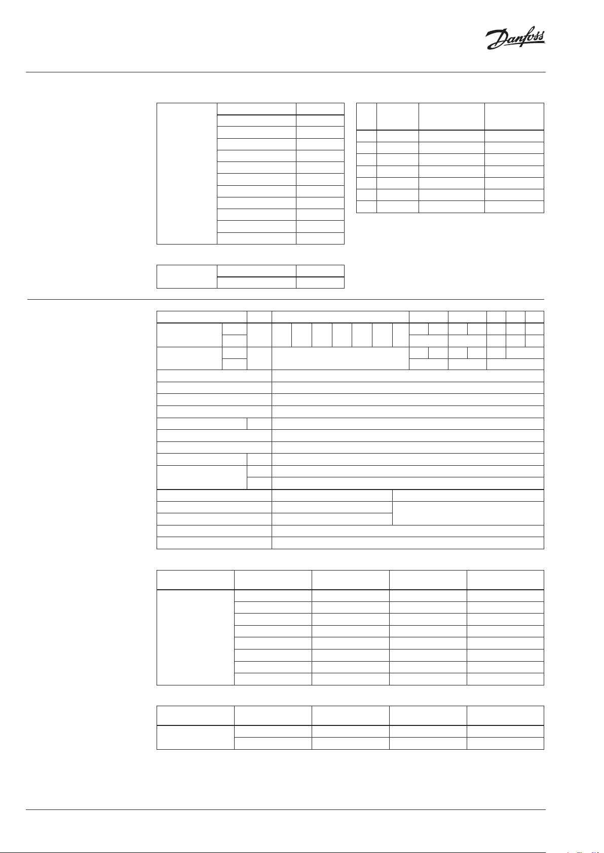
Ordering (continuous)
Technical data
Spare parts VM 2
Valve insert
Valve s ize Code No.
DN 15/1,0 065B2033
DN 15/1,6 065B2034
DN 15/ 2,5 065B2035
DN 15/4,0 065B2036
DN 20/4,0 065B2036
DN 20/6, 3 065B2037
DN 25/6, 3 065B2037
DN 25/8,0 065B2041
DN 32 /10 065B2038
DN 4 0/16 065B2039
DN 50/25 065B2040
Accessories for VM 2 (set of 2 tailpieces)
Ext. thread
DN
ISO 228/1
15 G ¾ A 003H6908 003H6902
20 G 1 A 003H6909 0 03H6903
25 G 1¼ A 0 03H6910 003H690 4
32 G 1⁄ A 0 03 H69 11
32 G 1½ A 003 H6914
40 G 2 A 065B2006 065B2004
50 G 2½ A 065B2007 065B2005
1)
weld-o n tailpieces (steel), ext thre ad (brass)
2)
for valve code No. 0 65B2029 (G 1⁄ A)
3)
for valve code No. 0 65B2018 (G 1½ A)
Weld-on tailpieces
Code No. Cod e No.
2)
3)
Spare parts VB 2
Stuffing box
Nominal diameter
kVS value
Stroke
Control range > 50:1
Control characteristic split characteristic
Cavitation factor z ≥ 0,5
Leakage acc. to standard IEC 534 max. 0,05% of k
Nominal pressure
Medium Circulation water / Glycolic water up to 30 %
Medium pH Min. 7, Max. 10
Medium temperature
Connections
Materials VM2 VB2
Valve body Red bronze (Rg 5) Ductile iron
Valve cover -
Valve cone, seat and stem Stainless steel
Stuffing box sealing EPDM O-rings
Valve s ize Code No.
DN 15- 50 065B2070
DN
VM 2
m3/h 0,25 0,40 0,63 1,0 1,6 2,5 4,0
VB 2 6,3 10 16 25 40
VM 2
mm 5
VB 2 5 7 10
PN
°C
VM 2
VB 2
15 20 25 32 40 50
4,0 6,3 6,3 8,0 10 16 25
5 7 5 5 7 10
VS
25
2 … 150
External thread acc. to ISO 228-1
Flange PN 25 ass. to EN 1092-2
EN-GJS-400-18-LT (GGG 40.3)
Tailpieces with
1)
ext. thread
003H6905
003H6906
1)
2)
3)
2 | © Danfoss | 2017.03
Δp closing pressure VM 2
Typ e
VM 2
DN k
(mm) (m3/h) (bar) (bar)
VS
15 0,25-4,0 16 16
20 4,0 25 25
20 6,3 16 25
25 6,3 16 25
25 8,0 16 25
32 10 16 25
40 16 - 16
50 25 - 16
AMV(E) 10/13 AMV(E) 20/ 23, 30/33
Δp closing pressure VB 2
Typ e
VB 2
DN k
(mm) (m3/h) (bar) (bar)
15-25 0, 25-10 16 16
32-50 16-40 - 16
VS
Max. closing pressure: 16bar or 25 bar (see table above) depends on valve and actuator combination.
Max. closing pressure means that the valve can close against this pressure if the pressure is applied after closing of the valve.
Max. operating pressure: 12bar (recommended 4bar to avoid high noise level and cavitation).
Max. operating pressure means no sucking will occur in entire valve stroke and valve can close against this pressure
from open position.
AMV(E) 10/13 AMV(E) 20/ 23, 30/33
ED.LH.M4.02
Data sheet VM 2, VB 2
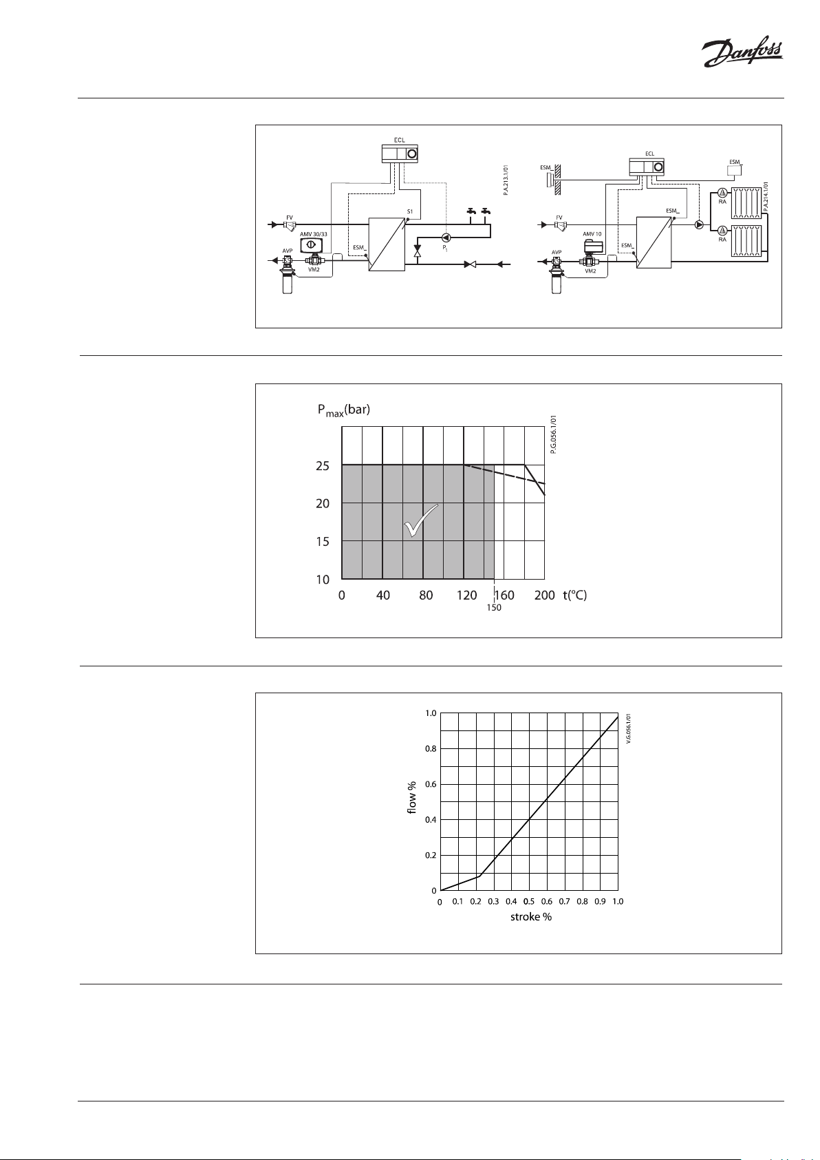
Application principles
Pressure temperature
diagram
Split characteristic
Hot water service application with heat e xchanger
Maximum allowed operating pressure as a function of medium temperature (according to EN 1092-2 and EN 1092-3).
Heating application, indirect district heating substation
EN-GJS-400 -18-LT (GGG 40.3) PN 25
CuSn5ZnPb (Rg5) PN 25
Fast and stable regulation also at small flow rates. Less temperature oscillation.
Disposal The valve must be dismantled and the elements
sorted into various material groups before
disposal.
ED.LH.M4.02
© Danfoss | 2017.03 | 3
Data sheet VM 2, VB 2
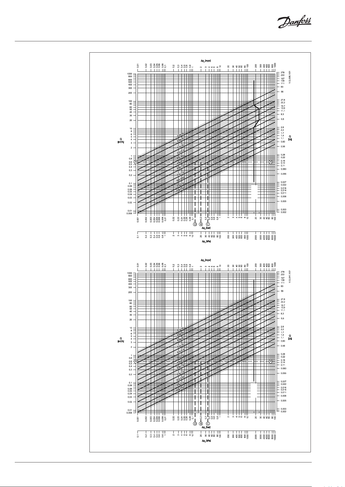
Sizing
max
p
VM 2
max
p
4 | © Danfoss | 2017.03
VB 2
ED.LH.M4.02

Data sheet VM 2, VB 2
21
1
pp
p
a authority, Valve
5,0
p2
p
a
1
1
64,0
2036
36
authorityhencevalve
41,0
2014
14
authorityhencevalve
Sizing (continuous)
Example
Design data:
Flow rate: 0,6 m3/h
System pressure drop: 20 kPa
Locate the horizontal line representing a flow
rate of 0,6 m3/h (line A-A). The valve authority is
given by the equation:
Where:
p1 = pressure drop across the fully open
valve
p2 = pressure drop across the rest of the
circuit with a full open valve
The ideal valve would give a pressure drop equal
to the system pressure drop (i.e. an authority of
0,5):
if: p1 = p
2
In this example an authority of 0,5 would be
given by a valve having a pressure drop of
20 kPa at that flow rate (point B). The intersection
of line A–A with a vertical line drawn from B lies
between two diagonal lines; this means that no
ideally-sized valve is available.
The intersection of line A–A with the diagonal
lines gives the pressure drops stated by real,
rather than ideal, valves. In this case, a valve with
kVS 1,0 would give a pressure drop of 36,0 kPa
(point C):
The second largest valve, with kVS 1,6, would give
a pressure drop of 14 kPa (point D):
Generally, the smaller valve would be selected
(resulting in a valve authority higher than 0,5
and therefore improved control). However, this
will increase the total pressure and should be
checked by the system designer for compatibility
with available pump heads, etc. The ideal
authority is 0,5 with a preferred range of
between 0,4 and 0,7.
ED.LH.M4.02
© Danfoss | 2017.03 | 5

Data sheet VM 2, VB 2
Dimensions
3
H
4
H
VM 2 + AMV(E) 10 VM 2 + AMV(E) 13 VM 2 + AMV(E) 20/30, 23/33
Typ e
H1H
VM 2 15 33 70 163 166 17 6 65 139 120 30 G ¾A 0,80
VM 2 20/4,0 33 70 163 166 176 70 15 4 131 37 G 1A 0,83
VM 2 20/6,3 33 70 163 166 176 70 15 4 131 37 G 1A 0,83
VM 2 25 38 70 163 16 6 176 75 159 14 5 46 G 1¼A 0,98
VM 2 32 38 70 163 16 6 176 100 18 4
VM 2 40 38 88 - - 194 11 0 244 200 64 G 2A 2,34
VM 2 50 44 88 - - 194 13 0 298 244 81 G 2½A 3,25
M30 ×1,5
SW
L
1
L
2
L
3
H
H
H
L
L
2
3
4
5
mm
1
Typ e DN
L3SW
2
177
63
182 G 1¾A 1, 22
kVS
(m3/h)
AMV(E) 10/13
15 0,25-4,0
2
H
20 4,0
20 6,3
1
H
VM 2
25 6,3-8,0
32 10
a
40 16
50 25
a
ISO 228/1
G 1½ A 1,18
AMV(E) 20/23;
AMV(E) 30/33
Weight
(kg)
5
H
6 | © Danfoss | 2017.03
Weld-on tailpieces
G
Ød
L
Weld on
Ød L
DN
G
(“)
mm
15 ¾ 15 35 0,18
20 1 20 40 0,26
25 1 ¼ 27 40 0,38
1 ½ 35 40 0,48
32
1 ¾ 37 40 0,48
40 2 40 65 0,90
50 2 ½ 50 82 1,70
Weight
(kg)
Tailpieces with external threads
G
L
Ext. thread
DN
G R
“
15 ¾ ½ 25,5 0,18
20 1 ¾ 28,5 0,26
25 1 ¼ 1 33 0,38
1 ½ 1 ¼ 36,5 0,62
32
1 ¾ 1 ¼ 36,5 0,62
40 2 1 ½ 43 0,9 0
50 2 ½ 2 55 1,70
L
(mm)
R
Weight
(kg)
ED.LH.M4.02

Data sheet VM 2, VB 2
Dimensions (continuo us)
M30 ×1,5
45°
1
H
DC
L
2
H
d
3
H
n
VB 2 + AMV(E) 10 VB 2 + AMV(E) 13 VB 2 + AMV(E) 20/30, 23/33
H
H
H
H
Typ e
VB 2 15
VB 2 20
VB 2 25
VB 2 32
VB 2 40
VB 2 50
1
2
3
L DC d n
4
mm
99 192 195 205 130 65 14 4 3,40
99 192 195 205 150 75 14 4 4,23
99 192 195 205 160 85 14 4 4,65
123 - - 229 180 10 0 18 4 8,40
123 - - 229 200 110 18 4 9,24
123 - - 229 230 12 5 18 4 10,91
Weight
(kg)
4
H
ED.LH.M4.02
Typ e DN
VB 2
15-2 5 0, 25-10
32-50 16-40
k
VS
(m3/h)
AMV(E) 10/13
AMV(E) 20/23;
AMV(E) 30/33
© Danfoss | 2017.03 | 7

Danf
already on order pro
All trademarks in this material are property of the respec
Data sheet VM 2, VB 2
oss can accept no responsibility for possible errors in catalogues, brochures and other printed material. Danfoss reserves the right to alter its products without notice. This also applies to products
vided that such alterations can be made without subsequential changes being necessary eady agreed.
8 | © Danfoss | DHS-SRMT/SI | 2017.03
tive companies. Danfoss and the Danfoss logotype are trademarks of Danfoss A/S. All rights reserved.
ED.LH.M4.02
 Loading...