

Page 1
Instructions
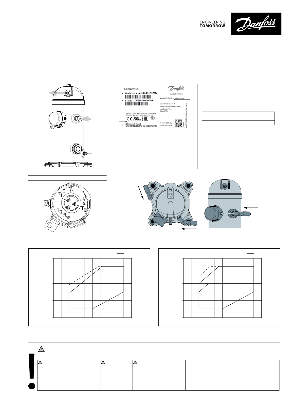
VLZ028-VLZ044 inverter compressors
VLZ028 - VLZ044 compressors can be
A
B
C
D
A: Model number
B: Serial Number
C: Refrigerant
D: Manufacturing year
E: Supply voltage range
F: max operating current
G: Lubricant type and nominal charge
H: Electronic frequency &
compressor frequency
powered by the dedicated variable speed
drive CDS803.
E
When Danfoss drive is selected, check carefully
F
for compatibility between compressor model
and variable speed drive.
G
Compressor
model
H
VLZ028-035-044 7.5 kW
Variable speed drive
rated power output
Electrical connections
Quick connect spade terminals
Operating limits
70
60
50
40
30
20
Condensing Temperature ºC
10
0
-35
-30 -25 -20 -15 -10 -5 0510 15
VLZ R448/449A Operating Map
Condition:135ºC Max DLT
50-100rps
30-100rps
Evaporating Temperature ºC
RGT20
SH10K
push
push
VLZ R404A Operating Map
Condition:135ºC Max DLT
70
60
50
40
30
20
Condensing Temperature ºC
10
0
-35
-30 -25 -20 -15 -10 -5 0510 15
Evaporating Temperature ºC
50-100rps
30-100rps
push
RGT20
SH10K
All the above limits, temperatures and speeds, are secured by parameters in the drive and application controller softwares.
Installation and servicing of the compressor by qualied personnel only. Follow these instructions and sound refrigeration engineering
practice relating to installation, commissioning, maintenance and service.
The compressor must only be
used for its designed purpose(s)
and within its scope of application
(refer to «operating limits»). Consult
Application guidelines and datasheet
available from cc.danfoss.com
1 | © Danfoss | DCS (CC)| 2017.07
Never operate
compressor
without terminal
box cover in place
and secured.
Under all circumstances,
the EN378 (or other applicable
local safety regulation)
requirements must be fullled.
Wear protective goggles and
work gloves.
The compressor must
be handled with
caution in the vertical
position (maximum
oset from the
vertical : 15°).
The compressor is delivered under
nitrogen gas pressure (between
0.3 and 0.4 bar / 4 and 6 psi). Do
not disassemble bolts, plugs,
ttings, etc... unless all pressure
has been relieved from the
compressor.
8510286P01B - FRCC.PI.039.A3.02
Page 2
RELAY
2
CDS803
Instructions
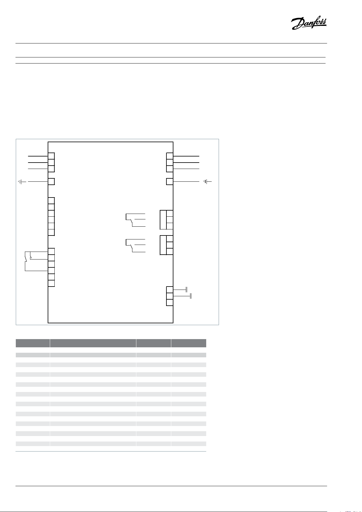
Basic connections
- Depending on the frequency converter version, the physical position of individual connectors may dier from below diagram.
- Always make sure that the compressor termi-
nals T1, T2, T3 are connected to the frequency
converter terminals 96, 97, 98 respectively.
- The compressor motor cable must be shielded
L1 91 L1 U 96 T1/U
L2 92 L2 V 97 T2/V
L3 93 L3 W 98 T3/W
95 PE PE 99
45 0/4-20 mA A OUT / DIG OUT
42 0/4-20 mA A OUT / DIG OUT
50 +10 V OUT NC
53 A IN NO 02
54 A IN COM 01
55 COM A IN/OUT
12 +24 V OUT COM 04
18 DIGI IN
19 DIGI IN
27 DIGI IN
29 DIGI IN
20 COM D IN
and the armoured part must be connected to
ground on both cable ends; at the side of the
compressor and at the side of the frequency converter.
- Use an EMC cable gland for cable installation and
perfect grounding; The metallic terminal box of
the compressor has a paint-free surface around
1
03
RELAY
NC 06
NO 05
N RS-485 69
P RS-485 68
Com RS-485 61
the connection hole for better conductivity.
- A low pressure safety switch is mandatory
to avoid compressor vacuum operation.
- At start-up, verify that the compressor rotates
in the right direction and pumps.
Legends:
Ana: Analogue
Dig: Digital
in: Input
out: Output
COM: Common
NC: Normally-closed
NO: Normally-open
91,92,93 3 phases mains input x x
95 Earth x x
42,45 0/4-20 mA Analague Output or Digital Output - -
50 +10V DC Output - 53 0-10V or 4-20mA Analague Input x 54 0-10V or 4-20mA Analague Input - x
55 Com Analague In/Out x 12 +24V output - 18 External On/O(NO) x x
19 Digital Input - 27 Safety Device x x
29 Digital Input - 20 Com Digital Input - 98 To Compressor T3 x x
97 To Compressor T2 x x
96 To Compressor T1 x x
99 Earth x x
03,02,01 Relay 1 - 06,05,04 Relay 2 - -
69,68 RS485 Bus - -
61 RS485 Bus Com - -
-: Optional connection
X: Mandatory connection
2 | © Danfoss | DCS (CC) | 2017.07
Open loop Process loop
The CDS803 frequency converter is factory
preset with parameters for the open loop
control principle. The process loop control
principle can be selected by changing
parameters in the «Quick menu».
Open loop: preset on input 53
0 - 10 V control
Frequency converter in slave mode
Process loop: preset on input 54
4 - 20 mA control
Frequency converter under own PID controller
8510286P01B - FRCC.PI.039.A3.02
Page 3

Instructions
1 – Introduction
These instructions pertain to the VLZ028VLZ044 variable scroll compressors used for airconditioning and reversible heat pump systems
in residential applications. They provide necessary information regarding safety and proper usage of this product.
2 – Handling and storage
• Handle the compressor with care. Use the dedicated handles in the packaging. Use the compressor lifting lug and use appropriate and safe
lifting equipment.
• Store and transport the compressor in an upright position.
• Store the compressor between -35°C and 55°C
/ -31°F and 131°F.
• Don’t expose the compressor and the packaging to rain or corrosive atmosphere.
3 – Safety measures before assembly
Never use the compressor in a ammable at-
mosphere.
• The compressor ambient temperature may
not exceed 55°C during o-cycle.
• Mount the compressor on a horizontal at surface with less than 7° slope.
• When installing a compressor model VLZ, use
equipment specically reserved for HFC refrigerants, which was never used for CFC or HCFC
refrigerants.
• Use clean and dehydrated refrigeration-grade
copper tubes and silver alloy brazing material.
• Use clean and dehydrated system components.
• The piping connected to the compressor must
be exible in 3 dimensions to dampen vibrations.
• The compressor must always be mounted using
the rubber grommets supplied with the compressor.
4 – Assembly
• Slowly release the nitrogen holding charge
through discharge and suction ports.
• Connect the compressor to the system as soon
as possible to avoid oil contamination from
ambient moisture.
• Avoid material entering into the system while
cutting tubes. Never drill holes where burrs
cannot be removed.
• Braze with great care using state-of-the-art
technique and vent piping with nitrogen gas
ow.
• Connect the required safety and control devices.
5 – Leak detection
Never pressurize the circuit with oxygen or
dry air. This could cause re or explosion.
• Do not use leak detection dye.
• Perform a leak detection test on the complete system.
• The low side test pressure must not exceed
31 bar /450 psi.
• When a leak is discovered, repair the leak and
repeat the leak detection.
6 – Vacuum dehydration
• Never use the compressor to evacuate the system.
•
Connect a vacuum pump to both the LP & HP sides.
• Pull down the system under a vacuum of 500
µm Hg (0.67 mbar) / 0.02 inch Hg absolute.
• Do not use a mega ohmmeter nor apply power
to the compressor while it is under vacuum as
this may cause internal damage.
7 – Electrical connections
• Switch o and isolate the main power supply.
• Before touching any potentially live part of the
drive, wait at least 4 minutes.
• The compressor is protected against excess
current by the frequency converter. Follow local regulations regarding power line protection.The compressor must be connected to
ground.
• Use 6.3 mm tabs for quick connect spade terminals.
• Use a self-tapping screw to connect the ground
conductor to the compressor.
• Care must be taken during installation to
ensure that the compressor operates in the
correct direction. T1 (U), T2 (V) and T3 (W) terminals of compressor and drive U, V, W must
match. Please refer to drawings for typical wiring connections and examine the specic wiring diagram located in the frequency converter
package. For further details, refer to the application guidelines.
• Mounting: The base frame of the frequency
converter must be very well xed to the support to ensure a very good continuity between
the ground potential of all electrical panels and
electrical boxes of the system.
• Wiring: All control wires have to be of a
screeened design. The cable for electrical motor supply has to be of a shielded design as
well. Correct earthing of the shield cover has to
be done using the method shown on drawings,
every time this one has to be earthed on each
end of the cables. Distinct cable trays must be
used for control and motor supply.
• The frequency converter ensures direct motor
protection and the factory set parameters are
such to protect the motor over all current malfunctions.
An external overload is not necessary.
• Set the frequency converter parameters in
accordance with Danfoss recommendations
for the CDS803 frequency converter and VLZ
variable speed compressor.
• Refer to variable speed drive manual for electrical connections details and installation.
• Compressor motor protection is provided by
the variable speed drive.
8 – Filling the system
• Keep the compressor switched o.
• Fill the refrigerant in liquid phase into the
outlet of the condenser or the liquid receiver.
The charge must be as closed as possible to
the nominal system charge to avoid low pressure operation and excessive superheat. For
VLZ028-044, the refrigerant charge limit is
3.6kg.Above this limit; protect the compressor
against liquid ood-back with a pump-down
cycle not lower than 1.1 bar(g) for R448A/1.1
bar(g) for R449A/ 1.6 bar(g) for R404A or a suction line accumulator.
• Never leave the lling cylinder connected to
the circuit.
9 – Verification before commissioning
Use safety devices such as safety pressure
switch and mechanical relief valve in compliance with both generally and locally applicable
regulations and safety standards. Ensure that
they are operational and properly set.
Check that the settings of high-pressure
switches do not exceed the maximum service
pressure of any system component.
•
A low-pressure switch is mandatory to avoid
vacuum operation.
Refrigerant R448A R449A R404A
Min. low pressure
safety switch setting
• Verify that all electrical connections are prop-
erly fastened and in compliance with local
regulations.
• When using a dome sensor, ensure the dome
sensor is correctly installed and tted into
bracket on top of the shell. The sensor need
to be well connected, especially after maintenance operations.
• After comissioning it is strongly recommended
to keep the frequency converter always energized.
10 – Start-up
• Never start the compressor when no refriger-
ant is charged.
• Do not provide any power to the drive unless
suction and discharge service valves on compressor are open, if installed.
• Energize the drive. The compressor must start,
according to dened ramp-up settings. If the
compressor does not start, check wiring conformity.
• Check the frequency converter control panel:
If any alarm is displayed check the wiring and
in particular the polarity of the control cables.
If an alarm is shown, refer to the frequency
converter application manual. Verify in particular the combination of compressor, frequency
converter and refrigerant.
bar(g) 0.8 0.8 1. 3
8510286P01B - FRCC.PI.039.A3.02
© Danfoss | DCS (CC) | 2017.07 | 3
Page 4

• Check current draw and voltage levels on the
mains. The values for the compressor electrical motor can be directly displayed on the frequency converter control panel.
• The optimum compressor suction superheat is
around 6K.
• Eventual reverse rotation can be detected by
following phenomena; the excessive noise,
no pressure dierential between suction and
discharge, and line warming rather than immediate cooling. A service technician should be
present at initial start-up to verify that wiring
from drive to compressor is properly phased
and that the compressor is rotating in the correct direction.
• Note that a 300 seconds period is necessary between 2 starts, a shorter period will be not allowed by the drive. The minimum running time
is 12s for each start.
11 – Check with running compressor
Check current draw and voltage. Measurement of amps and volts during running conditions must be taken at other points in the power
supply, not in the compressor electrical box.
• Check suction superheat to reduce risk of slug-
ging.
• Observe the oil level at start and during opera-
tion to conrm that the oil level remains visible. Excess foaming in oil sight glass indicates
refrigerant on the sump.
• Monitor the oil sight glass for 1 hour after sys-
tem equilibrium to ensure proper oil return to
the compressor. This oil check has to be done
over the speed range to guarantee:
- a good oil return at low speed with minimum
gas velocity.
- a good oil management at high speed with
maximum oil carry over.
• Respect the operating limits.
• Check all tubes for abnormal vibration. Move-
ments in excess of 1.5 mm / 0.06 inch require
corrective measures such as tube brackets.
• When needed, additional refrigerant in liquid
phase may be added in the low-pressure side
as far as possible from the compressor. The
compressor must be operating during this process.
• Do not overcharge the system.
• Never release refrigerant to atmosphere.
• Before leaving the installation site, carry out
a general installation inspection regarding
cleanliness, noise and leak detection.
• Record type and amount of refrigerant charge
as well as operating conditions as a reference
for future inspections.
• Compressor failure to build up pressure: Check
all bypass valves in the system to ensure that
none of these has been opened. Also check
that all solenoid valves are in their proper position.
• Abnormal running noise: Ensure the absence
of any liquid ood-back to the compressor by
means of measuring the return gas superheat
and compressor sump temperature. The sump
should be at least 6K above the saturated suction temperature under steady-state operating
conditions.
• The high-pressure switch trips out: Check condenser operations (condenser cleanliness, fan
operation, water ow and water pressure valve,
water lter, etc.). If all these are OK, the problem
may be due to either refrigerant overcharging
or the presence of a noncondensable (e.g. air,
moisture) in the circuit.
• The low-pressure switch trips out: Check evaporator operations (coil cleanliness, fan operations, water ow, water lter, etc.), liquid refrigerant ow and pressure drops (solenoid valve,
lter dryer, expansion valve, etc.), refrigerant
charge.
• Low refrigerant charge: The correct refrigerant
charge is given by the liquid sight glass indication, the condenser delta T in relation to the
refrigerant pressure tables (pressure-temperature), the superheat and the sub-cooling, etc.
(if additional charge is deemed necessary, refer
to section 8).
• Compressor short cycling: The number of cycles shall never exceed 6 starts per hour.
12 – Maintenance
Internal pressure and surface temperature are
dangerous and may cause permanent injury. Main
tenance operators and installers require appropriate skills and tools. Tubing temperature may exceed
100°C / 212°F and can cause severe burns.
Ensure that periodic service inspections to
ensure system reliability and as required by local
regulations are performed.
To prevent system related compressor problems,
following periodic maintenance is recommended:
• Verify that safety devices are operational and
properly set.
• Ensure that the system is leak tight.
• Check the compressor current draw by reading
one of the parameters via Modbus.
• Conrm that the system is operating in a way
consistent with previous maintenance records
and ambient conditions.
• Check that all electrical connections are still adequately fastened.
• Keep the compressor clean and verify the absence of rust and oxidation on the compressor
shell, tubes and electrical connections.
• Acid / moisture content in system and oil
should be checked regularly.
13 - Warranty
Always transmit the model number and serial
number with any claim led regarding this product.
Use the fault memory of the frequency converter to recover the fault descriptions before
initializing the system and even before shutting
o the power.
Variable speed drive model and serial number
must also be transmitted with the claim.
The product warranty may be void in following
cases:
• Absence of nameplate.
• External modications; in particular, drilling,
welding, broken feet and shock marks.
• Compressor opened or returned unsealed.
• Rust, water or leak detection dye inside the
compressor.
• Use of a refrigerant or lubricant not approved
by Danfoss.
• Any deviation from recommended instructions
pertaining to installation, application or maintenance.
• Use in mobile applications.
• Use in explosive atmospheric environment.
-
• No model number or serial number transmitted with the warranty claim.
14 – Disposal
Danfoss recommends that compressors
and compressor oil should be recycled
by a suitable company at its site.
Danfoss A/S
6430 Nordborg
Denmark
Danfoss can accept no responsibility for possible errors in catalogues, brochures and other printed material. Danfoss reserves the right to alter its products without notice. This
also applies to products already on order provided that such alterations can be made without subsequential changes being necessary in specications already agreed. All trademarks in this material are property of the respective companies. Danfoss and the Danfoss logotype are trademarks of Danfoss A/S. All rights reserved.
4 | © Danfoss | DCS (CC) | 2017.07
8510286P01B - FRCC.PI.039.A3.02
 Loading...