

Installation Guide
Pumping Smart Card
VLT® Soft Starter MCD 600


Installation Guide | Pumping Smart Card
Contents
Contents
1 Safety 5
1.1 Disclaimer 5
1.2 Warnings 5
2 Overview 6
2.1 Features of the Pumping Smart Card 6
2.1.1 Monitoring 6
2.1.2 Protection 6
2.1.3 Control 6
3 Setting up the Smart Card 7
3.1 Set-up Procedure 7
4 Installation 8
4.1 Installing the Expansion Card 8
4.2 Compatible Input Devices 8
4.3 Active and Passive 4–20 mA Input Devices 8
4.4 Minimizing Noise 9
4.5 Inputs 9
5 Operation 11
5.1 Monitoring 11
5.2 Protection and Monitoring 11
5.3 Protecting, Monitoring, and Controlling the Soft Starter 11
6 Configuration 12
6.1 Parameter Configuration 12
6.2 Off-line Configuration 12
6.3 Flow Protection 12
6.3.1 Operation 12
6.3.1.1 Using an Analog 4–20 mA Sensor 13
6.3.1.2 Using a Switch Sensor 13
6.3.1.3 Using a Pulse Sensor 13
6.3.2 Parameter Group 30-** Pump Input Configuration 14
6.3.3 Parameter Group 31-** Flow Protection 15
6.3.4 Parameter Group 36-** Pump Trip Action 15
6.4 Pressure Protection 16
6.4.1 Operation 17
6.4.1.1 Using an Analog 4–20 mA Sensor 17
6.4.1.2 Using a Switch Sensor 17
AN279052730268en-000102 / 175R1183 | 3Danfoss A/S © 2018.10

Installation Guide | Pumping Smart Card
6.4.1.3 Parameter Group 30-** Pump Input Configuration 18
6.4.1.4 Parameter Group 32-** Pressure Protection 18
6.4.1.5 Parameter Group 36-** Pump Trip Action 19
6.5 Pressure Control 20
6.5.1 Configuring Pressure Control 20
6.5.2 Operation 20
6.5.2.1 Level Control Operation 21
6.5.2.2 Pressure-based Operation 22
6.5.2.3 Parameter Group 30-** Pump Input Configuration 23
6.5.2.4 Parameter Group 33-** Pressure Control 23
6.5.2.5 Parameter Group 36-** Pump Trip Action 24
6.6 Depth Protection 24
6.6.1 Operation 25
6.6.1.1 Using an Analog 4–20 mA Sensor 25
6.6.1.2 Using a Switch Sensor 25
6.6.1.3 Parameter Group 30-** Pump Input Configuration 26
6.6.1.4 Parameter Group 34-** Depth Protection 26
6.6.1.5 Parameter Group 36-** Pump Trip Action 27
6.7 Thermal Protection 27
6.7.1 Parameter Group 35-** Thermal Protection 28
6.7.2 Parameter Group 36-** Pump Trip Action 28
Contents
7 Trip Messages 29
7.9 Pressure Sensor 31
8 Specifications 33
8.1 Connections 33
8.2 Certification 33
AN279052730268en-000102 / 175R11834 | Danfoss A/S © 2018.10
Installation Guide | Pumping Smart Card
Safety
1 Safety
1.1 Disclaimer
The examples and diagrams in this manual are included solely for illustrative purposes. The information contained in this manual is
subject to change at any time and without prior notice. Responsibility or liability is never accepted for direct, indirect, or consequential
damage resulting from the use or application of this equipment.
1.2 Warnings
WARN IN G
UNEXPECTED BEHAVIOR
When the soft starter is connected to mains voltage, the Pumping Smart Card can start or stop the motor without warning.
Unexpected behavior can lead to personal injury.
To ensure personnel safety, isolate the soft starter from mains voltage before installing the smart card.
-
WA RN IN G
RISK OF PERSONAL INJURY AND EQUIPMENT DAMAGE
Inserting foreign objects or touching the inside of the soft starter while the expansion port cover is open may endanger
personnel and can damage the soft starter.
Do not insert foreign objects in the soft starter with the port cover open.
-
Do not touch the inside of the soft starter with the port cover open.
-
NO TI CE
The hydraulic characteristics of pump systems vary considerably. The default parameter settings may not be suitable for every
application and care should be taken to configure the soft starter appropriately.
Danfoss A/S © 2018.10
AN279052730268en-000102 / 175R1183 | 5

Installation Guide | Pumping Smart Card
Overview
2 Overview
2.1 Features of the Pumping Smart Card
The Pumping Smart Card provides dedicated inputs for pressure, depth, temperature, and flow sensors to allow protection, control,
and monitoring integration in a range of pumping applications.
2.1.1 Monitoring
Data from analog or pulse sensors can be shown directly on the display of the soft starter.
A real-time graph is also available if the optional remote LCP is installed.
2.1.2 Protection
The smart card can trip the soft starter based on user-selected levels for high or low pressure, depth, temperature, or flow.
2.1.3 Control
The smart card can automatically start and stop the soft starter in response to rising or falling pressure, or rising or falling depth.
Smart card control can be used with the VLT® Soft Starter MCD 600 scheduling function to restrict starting or stopping to specified days
and times.
6 | Danfoss A/S © 2018.10
AN279052730268en-000102 / 175R1183
Installation Guide | Pumping Smart Card
Setting up the Smart Card
3 Setting up the Smart Card
3.1 Set-up Procedure
Context:
WA RN IN G
SHOCK HAZARD
Attaching or removing accessories while the soft starter is connected to mains voltage may cause personal injury.
Before attaching or removing accessories, isolate the soft starter from mains voltage.
-
Procedure
1. Insert the smart card into the soft starter.
2. Connect sensors to the inputs:
A Depth protection: B13, B14 or C13, C14
B Pressure protection: B23, B24 or C33, C34, C43, C44.
C Flow protection: B33, B34 or C23, C24.
D Motor temperature protection: R1, R2, R3.
E Pressure or depth-based control: B23, B24.
3. Configure the soft starter's auto-reset as required (parameter 6-1 Auto-Reset Count and parameter 6-2 Auto-Reset Delay).
4. Configure flow protection operation if required.
5. Configure pressure protection operation if required.
6. Configure pressure or depth-based control if required.
NO TI CE
Protection features still operate even if control is set to Off.
7. Configure depth protection if required.
8. Configure temperature protection if required.
9. Select the command source (parameter 1-1 Command Source).
• For protection and monitoring, use Digital input, Remote LCP, or Clock.
• For control, use Smart card or Smart card+Clock.
Danfoss A/S © 2018.10
AN279052730268en-000102 / 175R1183 | 7
1 2
e77ha739.10
Installation Guide | Pumping Smart Card
Installation
4 Installation
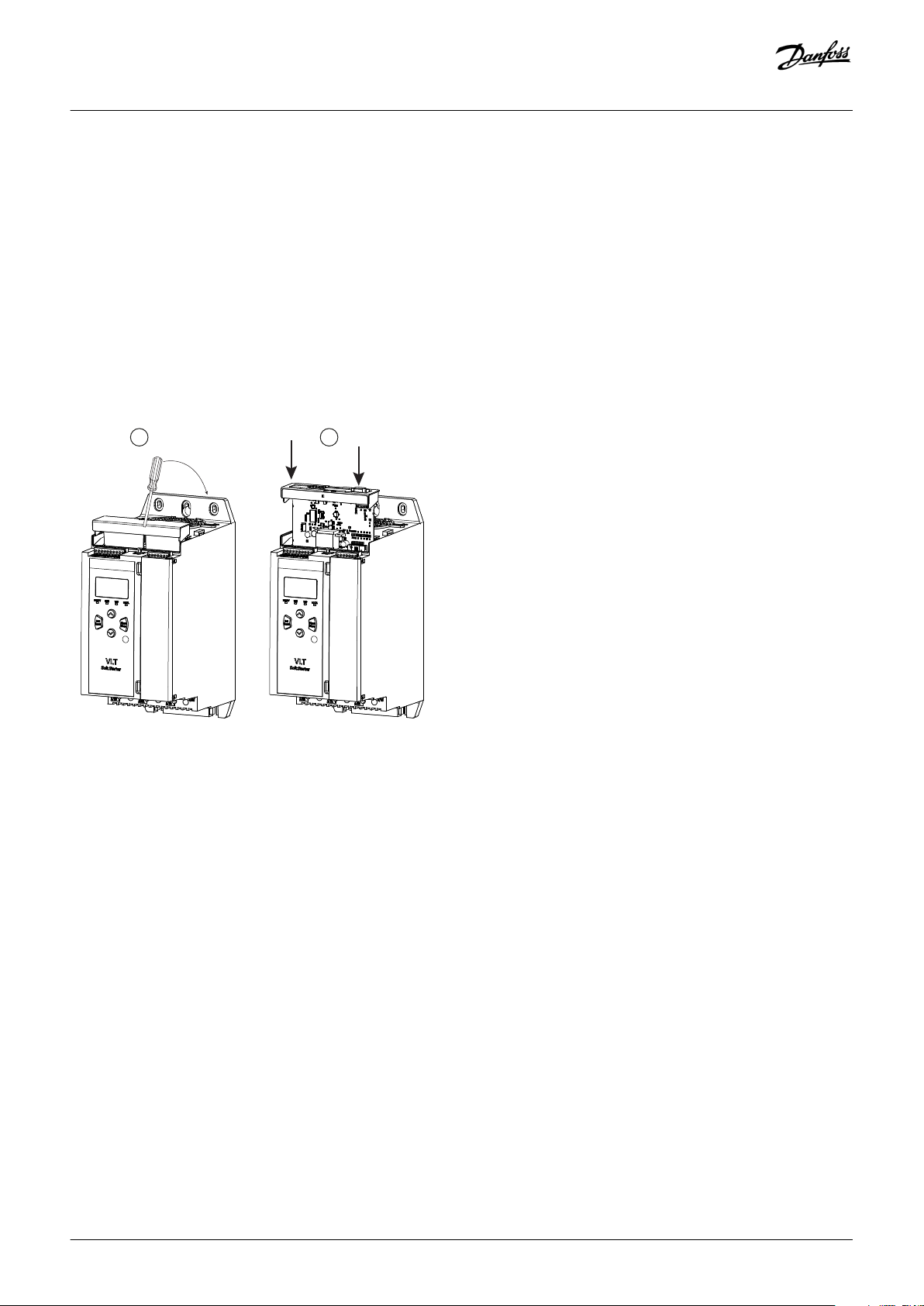
4.1 Installing the Expansion Card
Procedure
1. Push a small flat-bladed screwdriver into the slot in the center of the expansion port cover and ease the cover away from the soft
starter.
2. Line up the card with the expansion port.
3. Gently push the card along the guide rails until it clicks into the soft starter.
Example:
Illustration 1: Installation of the Expansion Cards
4.2 Compatible Input Devices
The smart card supports the following types of input devices:
• Analog 4–20 mA active (self-powered) and passive (loop-powered)
• Pulse
• Digital switch
4.3 Active and Passive 4–20 mA Input Devices
The wiring connections for 4–20 mA sensors vary depending on how the sensor is powered. This manual describes the wiring
connections for passive (loop-powered) sensors, but active (self-powered) sensors can also be used by changing the wiring
connections.
• Passive (loop-powered) sensors are powered from the 4–20 mA terminals of the smart card. For these sensors, use B13-B14, B23B24, B33-B34.
• Active (self-powered) sensors have either an internal or external power supply. The sensor is not powered from the smart card
terminals. For these sensors, connect the 0 V to terminal R1 and connect the active input to B13, B23, or B33 as required.
8 | Danfoss A/S © 2018.10
AN279052730268en-000102 / 175R1183
USB
DIGITAL INPUTS 4/20mA INPUTSRTD
Keypad
C24
C33
C34
C43
C13
C14
C23
C44
B14
B13B23
B24
B33
B34R2R1
R3
e77ha745.10
2
1
3
4
Installation Guide | Pumping Smart Card
Active and passive sensors can be used in the same installation.
4.4 Minimizing Noise
To minimize noise when using the analog 4–20 mA inputs, use twisted pair wiring.
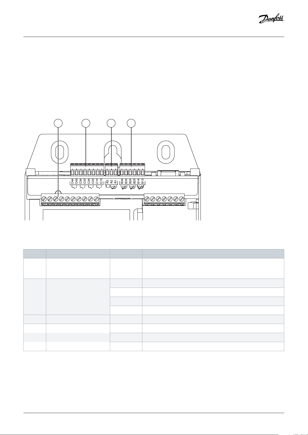
4.5 Inputs
Installation
Illustration 2: Location of Inputs
Table 1: Legend to Location of Inputs
Number Function Terminals Description
1 Reset input RESET, COM+ If the reset input is active, the soft starter does not operate. If a reset
switch is not required, fit a link across terminals RESET, COM+ on the
soft starter. The reset input is normally closed by default.
2 Digital inputs (normally open) C13, C14 Depth protection
C23, C24 Flow protection and monitoring
C33, C34 Low-pressure protection
C43, C44 High-pressure protection
3 RTD/PT100 input R1, R2, R3 Motor temperature protection
4 4–20 mA inputs B13, B14 [+] Depth protection and monitoring
B23, B24 [+] Pressure protection and monitoring/pressure or depth-based control
B33, B34 [+] Flow protection and monitoring
Danfoss A/S © 2018.10
AN279052730268en-000102 / 175R1183 | 9

Installation Guide | Pumping Smart Card
NO TI CE
The reset input can be configured for normally open or normally closed operation. Use parameter 7-9 Reset/ Enable Logic to
select the configuration.
NO TI CE
FLOW PROTECTION AND MONITORING
When used with a switch sensor, C23, C24 provide flow protection only. When used with a pulse sensor, C23, C24 provide flow
protection and monitoring.
Installation
10 | Danfoss A/S © 2018.10
AN279052730268en-000102 / 175R1183

Installation Guide | Pumping Smart Card
Operation
5 Operation
5.1 Monitoring
Data from analog or pulse sensors can be shown directly on the soft starter display.
A real-time graph is also available if the optional remote LCP is installed.
• To scroll to the graph screen, press [▵] and [▿].
• To change which data is shown on the graph, press [GRAPH] on the remote LCP.
5.2 Protection and Monitoring
The smart card can stop or trip the soft starter based on user-selected levels for high or low pressure, depth, temperature, or flow.
Smart card protection features are always active while the soft starter is operating. Protection levels are set via parameter groups 31 to
35.
5.3 Protecting, Monitoring, and Controlling the Soft Starter
Context:
The smart card can automatically start and stop the soft starter in response to rising or falling pressure, or rising and falling depth.
NO TI CE
Smart card protection features are always active while the soft starter is operating. Smart card protection is not affected by the
command source.
NO TI CE
To use the smart card to control the soft starter, use sensors connected to B23, B24.
NO TI CE
If the reset input is active, the soft starter does not operate. If a reset switch is not required, fit a link across terminals RESET,
COM+ on the soft starter.
Procedure
1. Set parameter 1-1 Command Source to Smart Card or Smart Card+Clock.
2. Set parameter 33-1 Pressure Control Mode as required.
3. Set parameter 4-1 Auto-Start/Stop Mode to Enable to use clock-based scheduling.
Danfoss A/S © 2018.10
AN279052730268en-000102 / 175R1183 | 11

C
B
A
2
1
D
E
e77ha746.10
Run
Ready
Time
Installation Guide | Pumping Smart Card
Configuration
6 Configuration
6.1 Parameter Configuration
Operating parameters for the Pumping Smart Card are set and stored in the soft starter. Parameters can be configured via the main
menu or uploaded using the USB Save & Load function.
For details on how to configure the soft starter, see the VLT® Soft Starter MCD 600 Operating Guide.
In the parameter descriptions, an asterisk (*) indicates the default setting.
6.2 Off-line Configuration
NO TI CE
Parameters for smart card functions are only visible in the parameter list if the smart card is installed.
To configure smart card settings in the soft starter before the card is installed, generate a parameter file in the MCD PC Software and
load it into the soft starter using USB Save & Load.
6.3 Flow Protection
Flow protection uses terminals B33, B34 or C23, C24 on the smart card.
• B33, B34: Use an analog 4–20 mA sensor.
• C23, C24: Use a normally open digital switch sensor for protection only, or use a pulse sensor for protection and monitoring.
Flow protection is active when the soft starter is in start, stop, or run mode.
The smart card trips the soft starter when the flow rate passes through the programmed trip level. If the flow rate is still outside the
expected operating range when the trip is reset (including auto-reset), the soft starter does not trip again.
6.3.1 Operation
A Off (Ready
C Flow protection active
12 | Danfoss A/S © 2018.10
B Start signal
D Protection event (parameter 31-1 High Flow Trip Level and
parameter 31-2 Low Flow Trip Level)
1 Flow protection start delay (parameter 31-3 Flow Start Delay)
AN279052730268en-000102 / 175R1183

Installation Guide | Pumping Smart Card
E Protection response (parameter 36-2 Flow Sensor, parameter
36-6 High Flow, parameter 36-7 Low Flow, parameter 36-8 Flow
Switch)
2 Flow protection response delay (parameter 31-4 Flow
Response Delay)
Illustration 3: Operation - Flow Protection
6.3.1.1 Using an Analog 4–20 mA Sensor
Context:
An analog 4–20 mA sensor provides protection and monitoring.
Procedure
1. Connect the sensor to B33, B34.
2. Set parameter 30-5 Flow Sensor Type to Analog.
3. Set parameters 30-6 to 30-8 according to the sensor specifications.
4. Set parameters 31-1 to 31-4, parameter 36-2 Flow Sensor, and parameter 36-7 Low Flow as required.
Configuration
6.3.1.2 Using a Switch Sensor
Context:
A switch sensor provides protection only.
Procedure
1. Connect the sensor to C23, C24.
2. Set parameter 30-5 Flow Sensor Type to Switch.
3. Set parameters 31-3 to 31-4, parameter 36-2 Flow Sensor, and parameter 36-8 Flow Switch as required.
Parameters 31-1 to 31-2 are not used with a switch sensor.
6.3.1.3 Using a Pulse Sensor
Context:
A pulse sensor provides protection and monitoring.
Procedure
1. Connect the sensor to C23, C24.
2. Set parameter 30-5 Flow Sensor Type to Pulses per Minute or Pulses per Unit.
3. Set parameter 30-6 Flow Units, 30-11 Units per Pulse, and either parameter 30-9 Units per Minute at Max Flow or parameter 30-10 Pulses
per Minute at Max Flow according to the sensor specifications.
4. Set parameters 31-1 to 31-4, and parameter 36-2 Flow Sensor, parameter 36-6 High Flow, and parameter 36-7 Low Flow as required.
Danfoss A/S © 2018.10
AN279052730268en-000102 / 175R1183 | 13

Installation Guide | Pumping Smart Card
6.3.2 Parameter Group 30-** Pump Input Configuration
Table 2: 30-5 - Flow Sensor Type
Option Function
Selects which type of sensor is associated with the flow sensor input on the smart card.
* None
Switch
Analog
Pulses per minute
Pulses per unit
Table 3: 30-6 - Flow Units
Option Function
Selects which units the sensor uses to report the measured flow.
* liters/second
Configuration
liters/minute
gallons/second
gallons/minute
Table 4: 30-7 - Flow at 4 mA
Range Function
*0 0–5000 Calibrates the soft starter to the 4 mA (0%) level of the flow sensor input.
Table 5: 30-8 - Flow at 20 mA
Range Function
*0 0–5000 Calibrates the soft starter to the 20 mA (100%) level of the flow sensor input.
Table 6: 30-9 - Units per Minute at Max Flow
Range Function
*0 0–5000 Calibrates the soft starter to the maximum flow volume of the flow sensor.
Table 7: 30-10 - Pulses per Minute at Max Flow
Range Function
*0 0–20000 Calibrates the soft starter to the maximum flow volume of the flow sensor.
Table 8: 30-11 - Units per Pulse
Range Function
*0 0–1000 Set to match how many units the flow sensor measures for each pulse.
14 | Danfoss A/S © 2018.10
AN279052730268en-000102 / 175R1183

Installation Guide | Pumping Smart Card
6.3.3 Parameter Group 31-** Flow Protection
Flow protection uses terminals B33, B34 or C23, C24 on the smart card.
Table 9: 31-1 - High Flow Trip Level
Range Function
*10 0–5000 Sets the trip point for high flow protection.
Table 10: 31-2 - Low Flow Trip Level
Range Function
* 5 1–5000 Sets the trip point for low flow protection.
Table 11: 31-3 - Flow Start Delay
Range Function
Configuration
*00:00:500 ms 00:00:100–
30:00:000
mm:ss:ms
Table 12: 31-4 - Flow Response Delay
Range Function
* 00:00:500 ms 00:00:100–30:00:000
mm:ss:ms
Sets a delay before a flow protection trip can occur. The delay is counted from the time a start
signal is received. The flow level is ignored until the start delay has elapsed.
Sets a delay between the flow passing the high or low flow trip levels, and the soft starter tripping.
6.3.4 Parameter Group 36-** Pump Trip Action
Table 13: 36-2 - Flow Sensor
Option Function
Selects the soft starter's response if it detects a fault with the flow sensor.
* Soft Trip and Log
Soft Trip and Reset
Trip Starter
Trip and Reset
Warn and Log
Log Only
Table 14: 36-6 - High Flow
Option Function
* Soft Trip and Log
Danfoss A/S © 2018.10
Selects the soft starter's response if the flow exceeds the high flow trip level (parameter 31-1 High Flow
Trip Level).
AN279052730268en-000102 / 175R1183 | 15

Installation Guide | Pumping Smart Card
Option Function
Soft Trip and Reset
Trip Starter
Trip and Reset
Warn and Log
Log Only
Table 15: 36-7 - Low Flow
Option Function
Selects the soft starter's response if the flow drops below the low flow trip level (set in parameter 31-2 Low
Flow Trip Level).
* Soft Trip and Log
Soft Trip and Reset
Trip Starter
Trip and Reset
Configuration
Warn and Log
Log Only
Table 16: 36-8 - Flow Switch
Option Function
Selects the soft starter's response if the flow sensor closes (switch type sensors only).
* Soft Trip and Log
Soft Trip and Reset
Trip Starter
Trip and Reset
Warn and Log
Log Only
6.4 Pressure Protection
Pressure protection uses terminals B23, B24 or C33, C34, C43, C44 on the smart card.
• B23, B24: Use an analog 4–20 mA sensor.
• C33, C34 (low-pressure protection): Use a normally open digital switch sensor.
• C43, C44 (high-pressure protection): Use a normally open digital switch sensor.
Pressure protection is active when the soft starter is in the start, run, or stop mode.
The smart card trips the soft starter when the pressure level passes through the programmed trip level. If the pressure is still outside
the expected operating range when the trip is reset (including auto-reset), the soft starter does not trip again.
16 | Danfoss A/S © 2018.10
AN279052730268en-000102 / 175R1183

C
B
A
2
1
D
E
e77ha746.10
Run
Ready
Time
Installation Guide | Pumping Smart Card
6.4.1 Operation
Configuration
A Off (Ready)
C Pressure protection active
E Protection response (parameter 36-1 Pressure Sensor,
parameter 36-4 High Pressure, parameter 36-5 Low Pressure)
2 Pressure protection response delay (parameter 32-3 High
Pressure Response Delay and parameter 32-6 Low Pressure
Response Delay)
Illustration 4: Operation - Pressure Protection
B Start signal
D Protection event (parameter 32-1 High Pressure Trip Level and
parameter 32-4 Low Pressure Trip Level)
1 Pressure protection start delay (parameter 32-2 High Pressure
Start Delay and parameter 32-5 Low Pressure Start Delay)
6.4.1.1 Using an Analog 4–20 mA Sensor
Context:
An analog 4–20 mA sensor provides protection and monitoring.
Procedure
1. Connect the sensor to B23, B24.
2. Set parameter 30-1 Pressure Sensor Type to Analog.
3. Set parameters 30-2 to 30-4 according to the sensor specifications.
4. Set parameters 32-1 to 32-6, parameter 36-1 Pressure Sensor, and parameters 36-4 to 36-5 as required.
6.4.1.2 Using a Switch Sensor
Context:
A switch sensor provides protection only.
Procedure
1. Connect the low-pressure sensor to C33, C34 and the high-pressure sensor to C43, C44.
2. Set parameter 30-1 Pressure Sensor Type to Switch.
3. High-pressure protection: Set parameters 32-2 to 32-3, parameter 36-1 Pressure Sensor, and parameter 36-4 High Pressure as required.
4. Low-pressure protection: Set parameters 32-5 to 32-6, parameter 36-1 Pressure Sensor, and parameter 36-5 Low Pressure as required.
Parameter 32-1 High Pressure Trip Level and parameter 32-4 Low Pressure Trip Level are not used with a switch sensor.
Danfoss A/S © 2018.10
AN279052730268en-000102 / 175R1183 | 17

Installation Guide | Pumping Smart Card
6.4.1.3 Parameter Group 30-** Pump Input Configuration
Table 17: 30-1 - Pressure Sensor Type
Option Function
Selects which type of sensor is associated with the pressure sensor input on the smart card.
* None
Switch
Analog
Table 18: 30-2 - Pressure Units
Option Function
Selects which units the sensor uses to report the measured pressure.
Bar
* kPa
Psi
Configuration
Table 19: 30-3 - Pressure at 4 mA
Range Function
*0 0–5000 Calibrates the soft starter to the 4 mA (0%) level of the pressure sensor input.
Table 20: 30-4 - Pressure at 20 mA
Range Function
*0 0–5000 Calibrates the soft starter to the 20 mA (100%) level of the pressure sensor input.
6.4.1.4 Parameter Group 32-** Pressure Protection
Pressure protection uses terminals B23, B24 or C33, C34, C44 on the smart card.
Table 21: 32-1 - High Pressure Trip Level
Range Function
*10 0–5000 Sets the trip point for high-pressure protection.
Table 22: 32-2 - High Pressure Start Delay
Range Function
* 0.5 s 00:00:100–
30:00:000
mm:ss:ms
18 | Danfoss A/S © 2018.10
Sets a delay before a high-pressure protection trip can occur. The delay is counted from the time a
start signal is received. The pressure is ignored until the start delay has elapsed.
AN279052730268en-000102 / 175R1183

Installation Guide | Pumping Smart Card
Table 23: 32-3 - High Pressure Response Delay
Range Function
Configuration
* 0.5 s 00:00:100–30:00:000
mm:ss:ms
Table 24: 32-4 - Low Pressure Trip Level
Sets a delay between the pressure passing the high-pressure trip level and the soft starter tripping.
Range Function
* 5 0–5000 Sets the trip point for low-pressure protection.
Table 25: 32-5 - Low Pressure Start Delay
Range Function
* 0.5 s 00:00:100–
30:00:000
Sets a delay before a low-pressure protection trip can occur. The delay is counted from the time a
start signal is received. The pressure is ignored until the start delay has elapsed.
mm:ss:ms
Table 26: 32-6 - Low Pressure Response Delay
Range Function
* 0.5 s 00:00:100–30:00:000
mm:ss:ms
Sets a delay between the pressure passing the low-pressure trip level and the soft starter tripping.
6.4.1.5 Parameter Group 36-** Pump Trip Action
Table 27: 36-1 - Pressure Sensor
Option Function
* Soft and Trip Log
Soft Trip and Reset
Trip Starter
Trip and Reset
Warn and Log
Log Only
Table 28: 36-4 - High Pressure
Option Function
Selects the soft starter's response if the pressure exceeds the high-pressure trip level (parameter 32-1 High
Pressure Trip Level) or the high-pressure switch sensor closes.
* Soft Trip and Log
Soft Trip and Reset
Trip Starter
Selects the soft starter's response if it detects a fault with the pressure sensor.
Danfoss A/S © 2018.10
AN279052730268en-000102 / 175R1183 | 19

Installation Guide | Pumping Smart Card
Option Function
Trip and Reset
Warn and Log
Log Only
Table 29: 36-5 - Low Pressure
Option Function
Selects the soft starter's response if the pressure drops below the low-pressure trip level (parameter 32-4
Low Pressure Trip Level) or the low-pressure sensor switch closes.
* Soft Trip and Log
Soft Trip and Reset
Trip Starter
Trip and Reset
Warn and Log
Log Only
Configuration
6.5 Pressure Control
The smart card can start or stop the soft starter (wake or sleep the pump) according to the measured pressure. This can be used for
direct pressure-based control, or the pressure measurement can be used to indicate water depth.
Other sensors can also be used to provide protection and monitoring.
Pressure control uses terminals B23, B24 on the smart card. Use an analog 4–20 mA sensor.
6.5.1 Configuring Pressure Control
Procedure
1. Connect the sensor to B23, B24.
2. Set parameter 30-1 Pressure Sensor Type to Analog.
3. Set parameters 30-2 to 30-4 according to the sensor specifications.
4. Set parameters 33-1 to 33-5 as required.
5. Set parameter 1-1 Command Source to Smart Card or Smart Card+Clock.
6.5.2 Operation
There are 2 different operating modes when using pressure control:
• Level control operation.
• Pressure-based operation.
20 | Danfoss A/S © 2018.10
AN279052730268en-000102 / 175R1183

2
1
4
3
A
D
B
C
e77ha748.10
20 mA
4 mA
A
Time
1
2
A
A
D
D
B
C
e77ha749.10
20 mA
4 mA
Time
Installation Guide | Pumping Smart Card
Configuration
6.5.2.1 Level Control Operation
A pressure sensor can be used to control the pump based on fluid level in a storage tank on the principle that deeper water exerts
higher pressure on the sensor.
Set parameter 33-1 Pressure Control Mode to Falling Pressure Start to fill the tank or Rising Pressure Start to empty the tank.
1 Parameter 32-1 High Pressure Trip Level
3 Pump wake (parameter 33-2 Start Pressure Level)
A Pump on (wake)
C Falling fluid level
Illustration 5: Falling Pressure (Fill Tank)
2 Pump sleep (parameter 33-4 Stop Pressure Level)
4 Parameter 32-4 Low Pressure Trip Level
B Pump off (sleep)
D Rising fluid level
1 Pump wake (parameter 33-2 Start Pressure Level) 2 Pump sleep (parameter 33-4 Stop Pressure Level)
Danfoss A/S © 2018.10
AN279052730268en-000102 / 175R1183 | 21

2
1
4
6 6
3
A
D
B
C
E
F
K
G
L
H
I
J
M
N
O
e77ha750.10
20 mA
4 mA
5 7
Analog output
Time
Installation Guide | Pumping Smart Card
Configuration
A Pump on (wake)
C Falling fluid level
Illustration 6: Rising Pressure (Tank Empty)
6.5.2.2 Pressure-based Operation
B Pump off (sleep)
D Rising fluid level
1 Parameter 32-1 High Pressure Trip Level
3 Pump wake (parameter 33-2 Start Pressure Level)
5 Parameter 33-5 Stop Response Delay
7 Parameter 6-2 Aute-Reset Delay
B Pipe filling
D Pressure at stop threshold, pump stops (sleep)
F Pressure below start threshold, start response delay
H Pump running
J Falling system pressure
L Low-pressure trip level
N Pump wakes
Illustration 7: Example of Pressure-based Operation
22 | Danfoss A/S © 2018.10
2 Pump sleep (parameter 33-4 Stop Pressure Level)
4 Parameter 32-4 Low Pressure Trip Level
6 Parameter 33-3 Start Response Delay
A Smart card control enabled, pump starts
C Normal pressure variation
E Falling system pressure
G Pump wakes
I Normal pressure variation
K Pressure below start threshold, start response delay
M Soft starter auto-reset
O Normal operation
AN279052730268en-000102 / 175R1183

Installation Guide | Pumping Smart Card
6.5.2.3 Parameter Group 30-** Pump Input Configuration
Table 30: 30-1 - Pressure Sensor Type
Option Function
Selects which type of sensor is associated with the pressure sensor input on the smart card.
* None
Switch
Analog
Table 31: 30-2 - Pressure Units
Option Function
Selects which units the sensor uses to report the measured pressure.
Bar
* kPa
Psi
Configuration
Table 32: 30-3 - Pressure at 4 mA
Range Function
*0 0–5000 Calibrates the soft starter to the 4 mA (0%) level of the pressure sensor input.
Table 33: 30-4 - Pressure at 20 mA
Range Function
*0 0–5000 Calibrates the soft starter to the 20 mA (100%) level of the pressure sensor input.
6.5.2.4 Parameter Group 33-** Pressure Control
Pressure control uses terminals B23, B24 on the smart card. Use an anlog 4–20 mA sensor.
Table 34: 33-1 - Pressure Control Mode
Option Function
Selects how the soft starter uses data from the pressure sensor to control the motor.
* Off The soft starter does not use the pressure sensor to control soft starting.
Falling Pressure
Start
The soft starter starts when the pressure drops below the level selected in parameter 33-2 Start Pressure
Level.
Rising Pressure
Start
Danfoss A/S © 2018.10
The soft starter starts when the pressure rises above the level selected in parameter 33-2 Start Pressure Lev-
el.
AN279052730268en-000102 / 175R1183 | 23

Installation Guide | Pumping Smart Card
Table 35: 33-2 - Start Pressure Level
Range Function
* 5 1–5000 Sets the pressure level to trigger the soft starter to perform a soft start.
Table 36: 33-3 - Start Response Delay
Range Function
Configuration
* 0.5 s 00:00:100–30:00:000
mm:ss:ms
Table 37: 33-4 - Stop Pressure Level
Range Function
* 10 0–5000 Sets the pressure level to trigger the soft starter to stop the motor.
Table 38: 33-5 - Stop Response Delay
Range Function
* 0.5 s 00:00:100–30:00:000
mm:ss:ms
Sets a delay between the pressure passing the pressure control start level and the soft starter performing a soft start.
Sets a delay between the pressure passing the pressure control stop level and the soft starter
stopping the motor.
6.5.2.5 Parameter Group 36-** Pump Trip Action
Table 39: 36-1 - Pressure Sensor
Option Function
Selects the soft starter's response if it detects a fault with the pressure sensor.
* Soft and Trip Log
Soft Trip and Reset
Trip Starter
Trip and Reset
Warn and Log
Log Only
6.6 Depth Protection
Depth protection uses terminals B13, B14 or C13, C14 on the smart card.
• B13, B14: Use an analog 4–20 mA sensor.
• C13, C14: Use a normally open digital switch sensor.
Depth protection is always active (ready, start, run, and stop modes).
The smart card trips the soft starter when the depth level passes through the programmed trip level. The trip cannot be reset until the
depth has returned above the reset level (parameter 34-2 Depth Reset Level).
24 | Danfoss A/S © 2018.10
AN279052730268en-000102 / 175R1183

C
B
A
1
D
E
e77ha747.10
Run
Ready
Time
Installation Guide | Pumping Smart Card
Configuration
NO TI CE
If the depth has not returned above the reset level when the soft starter auto-resets, the smart card trips the soft starter again.
6.6.1 Operation
A Off (ready)
C Start signal
E Protection response (parameter 36-3 Depth Sensor and
parameter 36-9 Well Depth)
Illustration 8: Operation - Depth Protection
B Depth protection active
D Protection event (parameter 34-1 Depth Trip Level)
1 Depth protection response delay (parameter 34-4 Depth
Response Delay)
6.6.1.1 Using an Analog 4–20 mA Sensor
Context:
An analog 4–20 mA sensor provides protection and monitoring.
Procedure
1. Connect the sensor to B13, B14.
2. Set parameter 30-12 Depth Sensor Type to Analog.
3. Set parameters 30-13 to 30-15 according to the sensor specifications.
4. Set parameters 34-1 to 34-4, parameter 36-3 Depth Sensor, and parameter 36-9 Well Depth as required.
6.6.1.2 Using a Switch Sensor
Context:
A switch sensor provides protection only.
Procedure
1. Connect the sensor to C13, C14.
2. Set parameter 30-12 Depth Sensor Type to Switch.
3. Set parameters 34-3 to 34-4, parameter 36-3 Depth Sensor, and parameter 36-9 Well Depth as required.
Parameters 34-1 to 34-2 are not used with a switch sensor.
Danfoss A/S © 2018.10
AN279052730268en-000102 / 175R1183 | 25

Installation Guide | Pumping Smart Card
6.6.1.3 Parameter Group 30-** Pump Input Configuration
Table 40: 30-12 - Depth Sensor Type
Option Function
Selects which type of sensor is associated with the depth sensor input on the smart card.
* None
Switch
Analog
Table 41: 30-13 - Depth Units
Option Function
Selects which units the sensor uses to report the measured depth.
* meters
feet
Table 42: 30-14 - Depth at 4 mA
Configuration
Range Function
*0 0–1000 Calibrates the soft starter to the 4 mA (0%) level of the depth sensor input.
Table 43: 30-15 - Depth at 20 mA
Range Function
*0 0–1000 Calibrates the soft starter to the 20 mA (100%) level of the depth sensor input.
6.6.1.4 Parameter Group 34-** Depth Protection
Depth protection uses terminals B13, B14 or C13, C14 on the smart card.
Table 44: 34-1 - Depth Trip Level
Range Function
* 5 0–1000 Sets the trip point for depth protection.
Table 45: 34-2 - Depth Reset Level
Range Function
* 10 0–1000 Sets the level for the soft starter to allow a depth trip to be reset.
Table 46: 34-3 - Depth Start Delay
Range Function
* 0.5 s 00:00:100–
30:00:000
Sets a delay before a depth protection trip can occur. The delay is counted from the time a start signal is received. The depth input is ignored until the start delay has elapsed.
mm:ss:ms
26 | Danfoss A/S © 2018.10
AN279052730268en-000102 / 175R1183

Installation Guide | Pumping Smart Card
Table 47: 34-4 - Depth Response Delay
Range Function
Configuration
* 0.5 s 00:00:100–30:00:000
mm:ss:ms
Sets a delay between the depth passing the depth protection trip level and the soft starter tripping.
6.6.1.5 Parameter Group 36-** Pump Trip Action
Table 48: 36-3 - Depth Sensor
Option Function
Selects the soft starter's response if it detects a fault with the depth sensor.
* Soft Trip and Log
Soft Trip and Reset
Trip Starter
Trip and Reset
Warn and Log
Log Only
Table 49: 36-9 - Well Depth
Option Function
Selects the soft starter's response if the depth drops below the depth trip level (parameter 34-1 Depth Trip
Level) or the depth switch sensor closes.
* Soft Trip and Log
Soft Trip and Reset
Trip Starter
Trip and Reset
Warn and Log
Log Only
6.7 Thermal Protection
Thermal protection uses terminals R1, R2, R3 on the smart card.
Thermal protection is active only when the soft starter is in run mode.
Danfoss A/S © 2018.10
AN279052730268en-000102 / 175R1183 | 27

Installation Guide | Pumping Smart Card
Configuration
6.7.1 Parameter Group 35-** Thermal Protection
Table 50: 35-1 - Temperature Sensor Type
Option Function
Selects which type of sensor is associated with the temperature sensor input on the smart card.
* None
PT100
Table 51: 35-2 - Temperature Trip Level
Range Function
* 40 ° 0–240 ° Sets the trip point for temperature protection. Use parameter 10-2 Temperature Scale to configure the tempera-
ture scale.
6.7.2 Parameter Group 36-** Pump Trip Action
Table 52: 36-10 - RTD/PT100 B
Option Function
* Soft Trip and Log
Soft Trip and Reset
Trip Starter
Trip and Reset
Warn and Log
Log Only
Selects the soft starter's response to the protection event.
28 | Danfoss A/S © 2018.10
AN279052730268en-000102 / 175R1183

Installation Guide | Pumping Smart Card
7 Trip Messages
7.1 Depth Sensor
Cause
The smart card has detected a fault with the depth sensor.
Troubleshooting
• Check the following parameters:
- Parameter 30-12 Depth Sensor Type.
- Parameter 36-3 Depth Sensor.
7.2 Flow Sensor
Cause
The smart card has detected a fault with the flow sensor.
Trip Messages
Troubleshooting
• Check the following parameters:
- Parameter 30-5 Flow Sensor Type.
- Parameter 36-2 Flow Sensor.
7.3 Flow Switch
Cause
The flow switch sensor (smart card terminals C23, C24) has closed.
Troubleshooting
• Check the following parameters:
- Parameter 30-5 Flow Sensor Type.
- Parameter 36-8 Flow Switch.
7.4 High Flow
Cause
The flow sensor connected to the smart card has activated high-flow protection.
Danfoss A/S © 2018.10
AN279052730268en-000102 / 175R1183 | 29

Installation Guide | Pumping Smart Card
Troubleshooting
• Check the following parameters:
- Parameter 30-5 Flow Sensor Type.
- Parameter 30-7 Flow at 4 mA.
- Parameter 30-8 Flow at 20 mA.
- Parameter 31-1 High Flow Trip Level.
- Parameter 31-3 Flow Start Delay.
- Parameter 31-4 Flow Response Delay.
- Parameter 36-6 High Flow.
7.5 High Pressure
Cause
The pressure sensor connected to the smart card has activated high-pressure protection.
Troubleshooting
• Check the following parameters:
- Parameter 30-1 Pressure Sensor Type.
- Parameter 30-3 Pressure at 4 mA.
- Parameter 30-4 Pressure at 20 mA.
- Parameter 32-1 High Pressure Trip Level.
- Parameter 32-2 High Pressure Start Delay.
- Parameter 32-3 High Pressure Response Delay.
- Parameter 36-4 High Pressure.
Trip Messages
7.6 Low Flow
Cause
The flow sensor connected to the smart card has activated low-flow protection. Related parameters:
Troubleshooting
• Check the following parameters:
- Parameter 30-5 Flow Sensor Type.
- Parameter 30-7 Flow at 4 mA.
- Parameter 30-8 Flow at 20 mA.
- Parameter 31-2 Low Flow Trip Level.
- Parameter 31-3 Flow Start Delay.
- Parameter 31-4 Flow Response Delay.
- Parameter 36-7 Low Flow.
30 | Danfoss A/S © 2018.10
AN279052730268en-000102 / 175R1183

Installation Guide | Pumping Smart Card
7.7 Low Pressure
Cause
The pressure sensor connected to the smart card has activated low-pressure protection.
Troubleshooting
• Check the following parameters:
- Parameter 30-1 Pressure Sensor Type.
- Parameter 30-3 Pressure at 4 mA.
- Parameter 30-4 Pressure at 20 mA.
- Parameter 32-4 Low Pressure Trip Level.
- Parameter 32-5 Low Pressure Start Delay.
- Parameter 32-6 Low Pressure Response Delay.
- Parameter 36-5 Low Pressure.
7.8 Low Water
Cause
Trip Messages
The depth sensor connected to the smart card has activated depth protection.
Troubleshooting
• Check the following parameters:
- Parameter 30-12 Depth Sensor Type.
- Parameter 30-14 Depth at 4 mA.
- Parameter 30-15 Depth at 20 mA.
- Parameter 34-1 Depth Trip Level.
- Parameter 34-2 Depth Reset Level.
- Parameter 34-3 Depth Start Relay.
- Parameter 36-9 Well Depth.
7.9 Pressure Sensor
Cause
The smart card has detected a fault with the pressure sensor.
Troubleshooting
• Check the following parameters:
- Parameter 30-1 Pressure Sensor Type.
- Parameter 36-1 Pressure Sensor.
Danfoss A/S © 2018.10
AN279052730268en-000102 / 175R1183 | 31

Installation Guide | Pumping Smart Card
7.10 RTD Circuit
Cause
The smart card has detected a fault with the RTD sensor, or the RTD has activated temperature protection.
Troubleshooting
• Check the following parameters:
- Parameter 35-2 Temperature Trip Level.
- Parameter 36-10 RTD/PT100 B.
Trip Messages
32 | Danfoss A/S © 2018.10
AN279052730268en-000102 / 175R1183

Installation Guide | Pumping Smart Card
Specifications
8 Specifications
8.1 Connections
External equipment Unpluggable connectors (supplied)
Maximum cable size
8.2 Certification
RCM IEC 60947-4-2
CE EN 60947-4-2
RoHS Compliant with EU Directive 2011/65/EU
2.5 mm2 (14 AWG)
Danfoss A/S © 2018.10
AN279052730268en-000102 / 175R1183 | 33

Installation Guide | Pumping Smart Card
Index
C
Cable size 33
Certification
CE
RCM 33
RoHS
Compatibility 8
E
Expansion port cover 8
F
Features
I
Inputs, location of 9
33
33
Index
6
L
Low flow 30
Low pressure
31
P
Programmable input
29
R
Real-time graph 6, 11
S
Sensors
Active
Analog 4–20 mA
Passive 8
Pulse sensor
Switch sensor 13, 17, 25
8, 13, 17, 25
13
T
Thermal protection
Tools
Flat-bladed screwdriver
27
8
8
W
Wiring
34 | Danfoss A/S © 2018.10
8
AN279052730268en-000102 / 175R1183

Installation Guide | Pumping Smart Card
Danfoss A/S © 2018.10
AN279052730268en-000102 / 175R1183 | 35

Danfoss can accept no responsibility for possible errors in catalogues, brochures and other printed material. Danfoss reserves the right to alter its products without notice. This also applies to products
already on order provided that such alterations can be made without subsequential changes being necessary in specifications already agreed. All trademarks in this material are property of the respective
companies. Danfoss and the Danfoss logotype are trademarks of Danfoss A/S. All rights reserved.
Danfoss A/S
Ulsnaes 1
DK-6300 Graasten
vlt-drives.danfoss.com
Danfoss A/S © 2018.10 MG15U102
*MG15U102
AN279052730268en-000102/ 175R1183
*
 Loading...