

Page 1
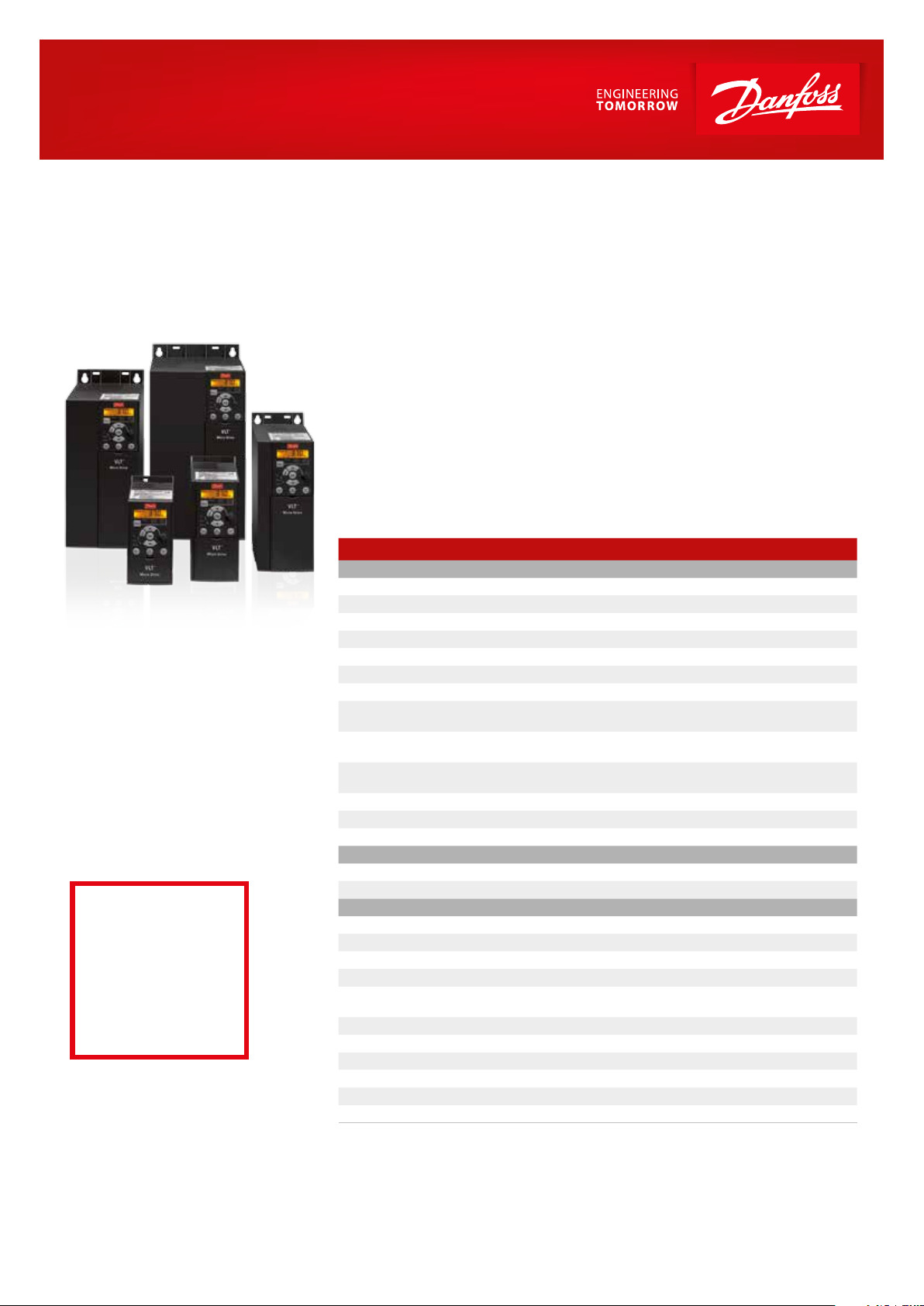
VLT® Micro Drive
The VLT® Micro Drive is a general purpose drive that can control AC motors up to 22 kW.
It’s a small drive with maximum strength and reliability.
Perfect
match for:
– Industrial appliances
– HVAC applications
– OEM
VLT® Micro Drive is a full member of
the VLT® family sharing the overall
quality of design, reliability and userfriendliness.
Due to high quality components and
genuine VLT® solutions, VLT® Micro
Drive is extremely reliable.
RoHS compliant
The VLT® Micro Drive is manufactured
with respect for the environment, and
it complies with the RoHS Directive.
Power range:
1 phase 200–240 V AC: 0.18–2.2 kW
3 phase 200–240 V AC: 0.25–3.7 kW
3 phase 380–480 V AC: 0.37–22 kW
Feature Benet
User-friendly
Minimum commissioning Saves time
Mount – connect – go! Minimum eort – minimum time
Copy settings via local control panel Easy programming of multiple drives
Intuitive parameter structure Minimal manual reading
Complies with VLT® software Saves commissioning time
Self-protecting features Lean operation
Process PI-controller No need for external controller
Automatic Motor Tuning
150% motor torque up to 1 minute
Flying start (catch a spinning motor)
Electronic Thermal Relay (ETR) Replaces external motor protection
Smart Logic Controller Often makes PLC unnecessary
Built-in RFI lter Saves cost and space
Energy saving Less operation cost
Energy eciency 98 %
Automatic Energy Optimisation (AEO) Saves 5–15% energy in HVAC applications
Reliable Maximum uptime
Earth fault protection Protects the drive
Over temperature protection
Short circuit protection Protects the drive
Optimum heat dissipation Longer lifetime
Unique cooling concept with no
forced air ow over electronics
High quality electronics Low lifetime cost
High quality capacitors Tolerates uneven mains supply
All drives full load tested from factory High reliability
Dust resistant Increased lifetime
RoHS compliant Protects the environment
Designed for WEEE Protects the environment
Ensures optimal match between
drive and motor
Plenty of brake-away and
acceleration torque
Doesn’t trip when started on a spinning
(freewheeling) motor
Minimises heat loss
Protects the motor and drive
Problem-free operation in
harsh environments
Page 2
Coated PCB standard
For harsh environments.
Power options
Danfoss VLT Drives oers a range
of external power options for use
together with our drives in critical
networks or applications:
n VLT® Advanced Harmonic Filter:
For applications where reducing
harmonic distortion is critical.
PC software tools
n MCT 10
Ideal for commissioning and
servicing the drive including
guided programming of cascade
controller, real-time clock, smart
logic controller and preventive
maintenance.
n VLT® Energy Box
Comprehensive energy analysis
tool, shows the drive payback
time.
n MCT 31
Harmonics calculations tool.
Specications
Mains supply (L1, L2, L3)
Supply voltage
Supply frequency 50/60 Hz
Displacement Power Factor (cos φ) near unity (> 0.98)
Switching on input supply L1, L2, L3 1–2 times/min.
Output data (U, V, W)
Output voltage 0–100% of supply voltage
Output frequency 0–200 Hz (VVC+ mode), 0–400 Hz (U/f mode)
Switching on output Unlimited
Ramp times 0.05–3600 sec
Digital inputs
Programmable digital inputs 5
Logic PNP or NPN
Voltage level 0–24 VDC
Pulse inputs
Programmable pulse inputs 1*
Voltage level 0–24 V DC (PNP positive logic)
Pulse input frequency 20–5000 Hz
* One of the digital inputs can be used for pulse inputs.
Analogue input
Analogue inputs 2
Modes 1 current/1 voltage or current
Voltage level 0 – 10 V (scaleable)
Current level
Analogue output
Programmable analogue outputs 1
Current range at analogue output 0/4–20 mA
Relay outputs
Programmable relay outputs 1 (240 VAC, 2 A)
Approvals
CE, C-tick, UL
Fieldbus communication
FC Protocol, Modbus RTU
1 x 200–240 V ± 10%, 3 x 200–240 V ±10 %
3 x 380–480 V ± 10%
0/4 to 20 mA (scaleable)
Ordering numbers
200 V 400 V
Power
[kW]
0.18 1.2 132F 0001
0.25 1.5 132F 0008
0.37 2.2 132F 0002 132F 0009 1.2 132 F 0 017
0.75 4.2 132F 0003 132F 0010 2.2 132F 0018
1.5 6.8 132F 0005 13 2F 0012 3.7 132F 0020
2.2 9.6 132F 0007 132F 0014 5.3 132F 0022
3.0 7.2 132F 0024
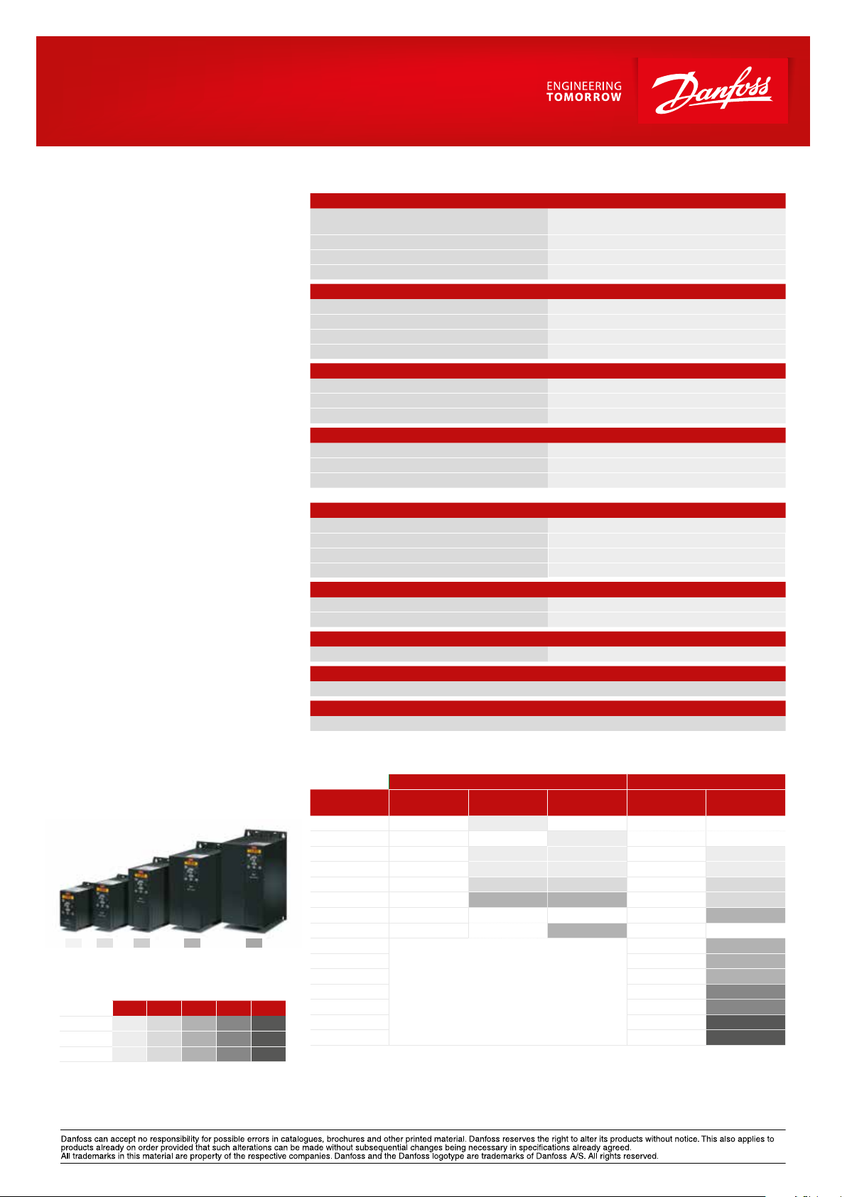
M3 M4 M5M2M1
Cabinet sizes
(mounting ange incl.)
[mm]
Height
Width 70 75 90 125 165
Depth 148 168 194 241 248
+ 6 mm with potentiometer
Danfoss VLT Drives, Ulsnaes 1, DK-6300 Graasten, Denmark, Tel. +45 74 88 22 22, Fax +45 74 65 25 80
www.danfoss.com/drives • E-mail: info@danfoss.com
DKDD.PFP.500.A2.02 VLT® is a trademark of Danfoss A/S Produced by PE-MMSC 2014.09
M1 M2 M3 M4 M5
150 176 239 292 335
3.7 15. 2 132F 0016
4.0
5.5 12. 0 132F 0028
7.5 15.5 132F 0030
11. 0 23.0 132F 0058
15. 0 31.0 132F 0059
18. 5 37.0 132 F 0060
22.0 43.0 132F 00 61
VLT® Control panel LCP 11 ............................................................................ Without potentiometer: 132B 0100
VLT® Control panel LCP 12 ....................................................................................With potentiometer: 132B0101
Current
[I-nom.]
Micro Drives from 1.5 kW and up
have built-in brake chopper
1 ph. 3 ph.
Current
[I-nom.]
9.0 132 F 0026
3 ph.
 Loading...