

Page 1
e30bv013.10
(1) (2) (3)
VLT®
Mains-Free Interface
Alarm
On
1
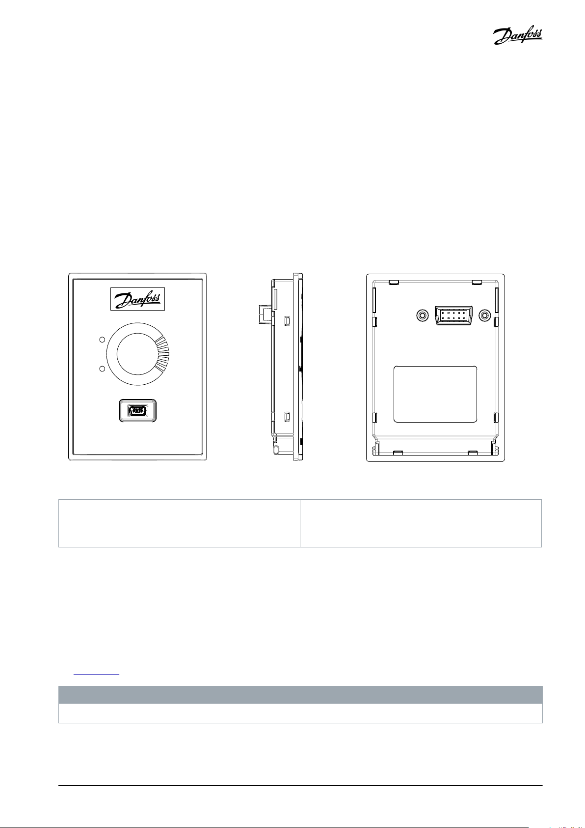
Front view
2
Side view
3
Back view
Installation Guide
VLT® Mains-Free Interface
VLT® HVAC Basic Drive FC 101
1 Installation and Usage
1.1 Description
This installation guide explains how to install and use the USB-based VLT® Mains-Free Interface.
1.2 Item Supplied
•
VLT® Mains-Free Interface (code number: 132B9222)
1.3 Product Overview
Illustration 1: VLT® Mains-Free Interface
The connection between the VLT® Mains-Free Interface and a PC is based on a USB 2.0 interface. A Mini-B USB connector is located
on the front side, and a standard drive connector is located on the back side.
Both VLT® Mains-Free Interface and the drive get current from the PC USB ports, thus the drive is mains free when the VLT® MainsFree Interface is installed on the drive.
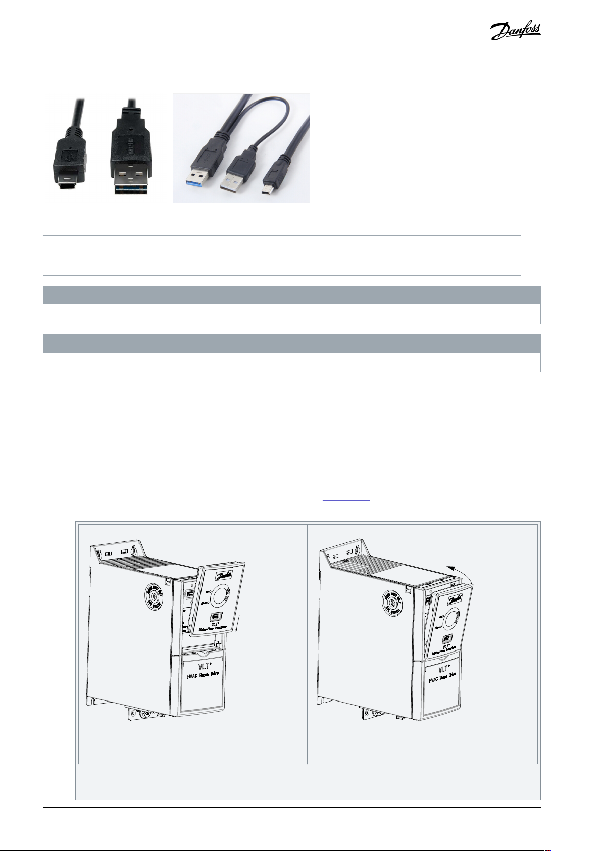
•
For drives of enclosure size H1–H5 and I2–I4, the required current is within the standard capability of a single USB port, and a
single USB type A connector can be used.
•
For drives of enclosure size H6–H10 and I6–I8, more than 500 mA current is required (500 mA is the maximum standard current
a USB port can deliver). It is recommended to use a double USB type A cable for connection to a PC. It is possible for the drive to
obtain the required current via both of the USB ports (the 2nd USB port is marked with Auxiliary power only).
See
Illustration 2 for the recommended cable examples.
N O T I C E
The cables are not provided with the VLT® Mains-Free Interface.
AN391118066887en-000101 / 130R1230 | 1Danfoss A/S © 2022.03
Page 2
e30bv052.10
(1) (2)
1
Example of a cable with a single USB type A connector
2
Example of a cable with 2 male connectors to the PC
e30bv053.10
Illustration 3: Position the VLT® Mains-Free Interface in the
Drive
e30bv054.10
Illustration 4: Push the Top of the VLT® Mains-Free Interface in-
to Place
VLT® Mains-Free Interface
Installation Guide
Illustration 2: Cable Examples
Installation and Usage
N O T I C E
Connecting the VLT® Mains-Free Interface to a live drive may impair the use of the standard RS485 port on the drive.
N O T I C E
For IP54 drives, the VLT® Mains-Free Interface can be used only for programming. To keep the IP54 level, LCP must be reinstalled.
1.4 Safety Precautions
Only qualified personnel are allowed to install the VLT® Mains-Free Interface described in this installation guide.
For important information about safety precautions for installation, refer to the drive's operating guide.
1.5 Installation
The VLT® Mains-Free Interface is physically identical to the local control panel (LCP 31) and connects to the same dedicated port on
the drive. The VLT® Mains-Free Interface can be mounted to the drive as follows:
Procedure
1.
Position the bottom of VLT® Mains-Free Interface in the drive, see Illustration 3.
2.
Push the top of VLT® Mains-Free Interface into place, see Illustration 4.
AN391118066887en-000101 / 130R12302 | Danfoss A/S © 2022.03
Page 3

e30bv014.10
VLT® Mains-Free Interface
Installation Guide
Installation and Usage
N O T I C E
The VLT® Mains-Free Interface can also be connected to the drive using the remote mounting kit cable or the RJ45
converter plugs.
1.6 Usage
1.6.1 Installing Driver on the PC
Before connecting the VLT® Mains-Free Interface, install the correct driver on the PC first.
Download the following files from Danfoss website https://suite.mydrive.danfoss.com/introduction.
•
For Win7 32 bits operating system, use dpinst_x86.exe.
•
For Win7 64 bits operating system, use dpinst_amd64.exe.
•
For Win10 32 bits operating system, use dpinst_x86.exe.
•
For Win10 64 bits operating system, use dpinst_amd64.exe.
N O T I C E
Minimum software versions to use the VLT® Mains-Free Interface is 4.23 on the drive, 10.11 on the test monitor, and 1.00 or later
of the VLT® Mains-Free Interface for firmware download and parameter/SIVP programming.
1.6.2 COM Port
Before configuring the COM port, the VLT® Mains-Free Interface must be installed on the drive and the correct driver must be installed on the PC.
Procedure
1.
Connect the VLT® Mains-Free Interface to the PC using the recommended cable.
A COM port whose name is Danfoss LCP Adapter is created when the VLT® Mains-Free Interface is connected to a
PC.
2.
Check the COM port number in Device Manager as shown in
The COM port number is 15 in the following example.
Illustration 5: COM Port Number Example
Illustration 5.
AN391118066887en-000101 / 130R1230 | 3Danfoss A/S © 2022.03
Page 4

e30bv015.10
LED status
Description
Starts flashing, and becomes solid after a few seconds.
Successful connection to the drive.
Keeps flashing.
Incompatibility between the drive software and the VLT® Mains-Free Interface.
VLT® Mains-Free Interface
Installation Guide
3.
The COM port created by the VLT® Mains-Free Interface can be used with the Danfoss PC communication tool (VLT® Motion
Control Tool MCT 10) or any standard terminal communication software. See the following example:
Illustration 6: MCT 10 Serial Fieldbus Configuration Menu
Installation and Usage
1.6.3 LED Indication
After successful connection between the VLT® Mains-Free Interface and PC, the green LED at the front of the VLT® Mains-Free Interface indicates the connection status, see Table 1.
Table 1: LED Indication
Danfoss A/S
Ulsnaes 1
DK-6300 Graasten
vlt-drives.danfoss.com
Danfoss can accept no responsibility for possible errors in catalogs, brochures, and other printed material. Danfoss reserves the right to alter its products without notice.
This also applies to products already on order provided that such alterations can be made without subsequential changes being necessary in specifications already
agreed. All trademarks in this material are property of the respective companies. Danfoss and the Danfoss logotype are trademarks of Danfoss A/S. All rights reserved.
*130R1230*
*M0034701*
AN391118066887en-000101 / 130R12304 | Danfoss A/S © 2022.03
 Loading...