

Page 1

MAKING MODERN LIVING POSSIBLE
Operating Instructions
VLT® Integrated Servo Drive ISD® 510 System
vlt-drives.danfoss.com
Page 2

Page 3

Contents Operating Instructions
Contents
1 Introduction
1.1 Purpose of the Operating Instructions
1.2 Additional Resources
1.3 Copyright
1.4 Approvals and Certications
1.5 System Overview
1.5.1 Areas of Application 8
1.6 Software
1.7 Terminology
2 Safety
2.1 Symbols Used in this Manual
2.2 General
2.3 Safety Instructions and Precautions
2.4 Important Safety Warnings
2.5 Qualied Personnel
2.6 Due Diligence
2.7 Intended Use
6
6
6
6
6
7
8
8
9
9
9
9
10
11
11
11
2.8 Foreseeable Misuse
2.9 Service and Support
3 System Description
3.1 Overview
3.2 Servo Drive
3.2.1 Servo Drive Types 14
3.2.2 Motor Components 14
3.2.2.1 Shaft 14
3.2.2.2 Brake (Optional) 14
3.2.2.3 Cooling 15
3.2.2.4 Thermal Protection 15
3.2.2.5 Built-In Feedback Devices 15
3.2.3 Drive Components 15
3.2.3.1 Connectors on the Servo Drives 15
3.3 Servo Access Box (SAB)
3.3.1 Connections on the SAB 19
3.3.1.1 STO Connectors 20
12
12
13
13
13
18
3.3.1.2 Mains Connectors 20
3.3.1.3 Brake Connectors 21
3.3.1.4 Relay Connectors 21
3.3.1.5 Encoder Connectors 21
MG75K102 Danfoss A/S © 12/2015 All rights reserved. 1
Page 4

Contents
VLT® Integrated Servo Drive ISD® 510 System
3.3.1.6 Ethernet Connectors (not included) 22
3.3.1.7 AUX Connectors 22
3.3.1.8 24/48 V IN Connector 22
3.3.1.9 UDC Connectors 22
3.3.1.10 Hybrid Cable PE 22
3.4 Local Control Panel (LCP)
3.4.1 Overview 23
3.4.2 Local Control Panel (LCP) Layout 23
3.5 Cables
3.5.1 Hybrid Cable 25
3.5.2 I/O and/or Encoder Cable 25
3.5.3 Additional Cables 25
3.6 Connection Cables/Cabling
3.6.1 Layout and Routing 26
3.6.1.1 Standard Cabling Concept for 2 Lines 26
3.6.1.2 Standard Cabling Concept for 1 Line 26
3.7 Software
3.8 Fieldbus
3.8.1 EtherCAT
3.8.2 Ethernet POWERLINK
®
4 Mechanical Installation
4.1 Transport and Delivery
23
25
26
27
27
27
®
28
29
29
4.1.1 Items Supplied 29
4.1.2 Transport 29
4.1.3 Inspection on Receipt 29
4.2 Safety Measures during Installation
4.3 Installation Environment
4.4 Preparation for Installation
4.4.1 Servo Drive 30
4.4.2 Servo Access Box (SAB) 31
4.5 Installation Procedure
4.5.1 Installation and Space Requirements 32
4.5.2 Installation Aids and Tools Required 32
4.5.3 Fitting Instructions Servo Drive 32
4.5.4 Tightening Torques 33
4.5.5 Fitting Instructions Servo Access Box (SAB) 33
5 Electrical Installation
5.1 Warnings
5.2 Electrical Environmental Conditions
29
29
30
32
35
35
35
2 Danfoss A/S © 12/2015 All rights reserved. MG75K102
Page 5

Contents Operating Instructions
5.3 EMC-Compliant Installation
5.4 Grounding
5.5 Mains Supply Requirements
5.6 Auxiliary Supply Requirements
5.7 Safety Supply Requirements
5.8 Connecting the Components
5.8.1 Servo Access Box 37
5.8.2 Servo Drive 39
5.8.2.1 Connecting/Disconnecting Hybrid Cables 39
5.8.2.2 Connecting/Disconnecting Cables from Ports X3, X4, and X5 41
6 Commissioning
6.1 Pre-Commissioning Checklist
6.2 ID Assignment
6.2.1 EtherCAT
6.2.2 Ethernet POWERLINK
6.2.2.1 Single Device ID Assignment 43
6.2.2.2 Multiple Device ID Assignment 43
®
35
35
36
36
36
37
43
43
43
43
®
43
6.3 Switching on the ISD 510 Servo System
6.4 Basic Programming
6.4.1 Programming with Automation Studio™
6.4.1.1 Requirements 44
6.4.1.2 Creating an Automation Studio™ Project
6.4.1.3 Connecting to the PLC 48
6.4.2 Programming with TwinCAT
®
6.4.2.1 ISD Deliverables 48
6.4.2.2 Creating a TwinCAT® Project 48
6.4.2.3 Conguration as a TwinCAT® NC Axis 54
6.4.2.4 Connecting to the PLC 55
6.4.3 Programming Guidelines 55
6.5 ISD Toolbox
6.5.1 Overview 56
6.5.2 System Requirements 56
6.5.3 Installation 56
6.5.4 ISD Toolbox Communication 56
44
44
44
44
48
56
6.5.4.1 Network Settings for Indirect Communication 57
6.5.4.2 Network Settings for Direct Communication with Ethernet POWERLINK
6.5.4.3 Network Settings for Direct Communication with EtherCAT
®
®
58
59
6.5.5 ISD Toolbox Commissioning 60
6.6 Motion Library
MG75K102 Danfoss A/S © 12/2015 All rights reserved. 3
62
Page 6

Contents
VLT® Integrated Servo Drive ISD® 510 System
6.6.1 Function Blocks 62
6.6.2 Simple Programming Template 62
7 Operation
7.1 Operating Modes
7.1.1 Motion Functions 63
7.2 Operating Status Indicators
7.2.1 Operating LEDs on the Servo Drive 64
7.2.2 Operating LEDs on the Servo Access Box 64
8 ISD Safety Concept
8.1 Applied Standards and Compliance
8.2 Abbreviations and Conventions
8.3 Qualied Personnel for Working with the STO Function
8.4 Safety Precautions
8.5 Functional Description
8.6 Installation
8.7 Operation of the ISD Safety Concept
8.7.1 Statusword 68
8.7.2 Error Codes 69
8.8 Fault Reset
63
63
63
66
66
66
66
67
68
68
68
69
8.9 Commissioning Test
8.10 Application Example
8.11 Safety Function Characteristic Data
8.12 Maintenance, Security, and User Accessibility
9 Diagnostics
9.1 Faults
9.2 Servo Drive
9.2.1 Troubleshooting 74
9.2.2 Error Codes 75
9.3 Servo Access Box (SAB)
9.3.1 Troubleshooting 77
9.3.2 Error Codes 78
10 Maintenance, Decommissioning, and Disposal
10.1 Maintenance Tasks
10.2 Inspection during Operation
10.3 Repair
69
72
73
73
74
74
74
77
81
81
82
82
10.3.1 Cable Replacement 82
10.3.1.1 Feed-In Cable Replacement 82
10.3.1.2 Loop Cable Replacement 83
4 Danfoss A/S © 12/2015 All rights reserved. MG75K102
Page 7

Contents Operating Instructions
10.4 Servo Drive Replacement
10.4.1 Dismounting 83
10.4.2 Fitting and Commissioning 83
10.5 SAB Replacement
10.5.1 Dismounting 83
10.5.2 Fitting and Commissioning 83
10.6 Decommissioning of the ISD 510 Servo System
10.7 Product Returns
10.8 Recycling and Disposal
10.8.1 Recycling 84
10.8.2 Disposal 84
11 Specications
11.1 Servo Drive
11.1.1 Nameplate 85
11.1.2 Characteristic Data 85
11.1.3 Dimensions 86
11.1.4 Permitted Forces 88
83
83
84
84
84
85
85
11.1.5 General Specications and Environmental Conditions 88
11.2 Servo Access Box
11.2.1 Nameplate 89
11.2.2 Characteristic Data 89
11.2.3 Dimensions 90
11.2.4 General Specications and Environmental Conditions 92
11.3 Cables
11.4 Storage
11.4.1 Long-Term Storage 92
12 Appendix
12.1 Glossary
Index
89
92
92
93
93
95
MG75K102 Danfoss A/S © 12/2015 All rights reserved. 5
Page 8

Introduction
VLT® Integrated Servo Drive ISD® 510 System
11
1 Introduction
1.1 Purpose of the Operating Instructions
The purpose of these operating instructions is to describe
the VLT® Integrated Servo Drive ISD® 510 System.
These operating instructions contain information about:
Installation
•
Commissioning
•
Programming
•
Operation
•
Troubleshooting
•
Service and maintenance
•
These operating instructions are intended for use by
qualied personnel. Read it in full to use the ISD 510 servo
system safely and professionally, and pay particular
attention to the safety instructions and general warnings.
These operating instructions are an integral part of the ISD
510 servo system and also contains important service
information. Therefore, keep it available with the ISD 510
servo system at all times.
Compliance with the information in these operating
instructions is a prerequisite for:
Trouble-free operation.
•
Recognition of product liability claims.
•
Therefore, read these operating instructions before working
with the ISD 510 servo system.
Additional Resources
1.2
Available manuals for the ISD 510 servo system:
Document Contents
VLT® Integrated Servo Drive
ISD® 510 System Operating
Instructions
VLT® Integrated Servo Drive
ISD® 510 System Design
Guide
VLT® Integrated Servo Drive
ISD® 510 System
Programming Guide
Table 1.1 Available Documents for the ISD 510 Servo System
Technical literature for Danfoss drives is also available
online at vlt-drives.danfoss.com/Support/Technical-Documen-
tation/.
Information about the installation,
commissioning, and operation of
the ISD 510 servo system.
Information about the set-up of
the ISD 510 servo system and
detailed technical data.
Information about the
programming of the ISD 510 servo
system.
Copyright
1.3
VLT®, ISD®, and SAB® are Danfoss registered trademarks.
1.4 Approvals and Certications
The ISD 510 servo system fullls the standards listed in
Table 1.2.
IEC/EN 61800-3 Adjustable speed electrical power drive
systems.
Part 3: EMC requirements and specic test
methods.
IEC/EN
61800-5-1
IEC/EN
61800-5-2
IEC/EN 61508 Functional safety of electrical/electronical/
EN ISO 13849-1 Safety of machinery - Safety-related parts of
EN ISO 13849-2 Safety of machinery - Safety-related parts of
IEC/EN 60204-1 Safety of machinery - Electrical equipment of
IEC/EN 62061 Safety of machinery - Functional safety of
IEC/EN
61326-3-1
UL508C UL Standard for Safety for Power Conversion
2006/42/EC Machinery Directive
CE
2014/30/EU EMC Directive
2014/35/EU Low Voltage Directive
RoHS
(2002/95/EC)
Adjustable speed electrical power drive
systems.
Part 5-1: Safety requirements - Electrical,
thermal and energy.
Adjustable speed electrical power drive
systems.
Part 5-2: Safety requirements - Functional.
programmable electronic safety-related
systems.
control systems.
Part 1: General principles for design.
control systems.
Part 2: Validation.
machines.
Part 1: General requirements.
safety-related electrical, electronic, and
programmable electronic control systems.
Electrical equipment for measurement, control,
and laboratory use – EMC requirements.
Part 3-1: Immunity requirements for safety-
related systems and for equipment intended
to perform safety-related functions (functional
safety) – General industrial applications.
Equipment.
Restriction of hazardous substances.
6 Danfoss A/S © 12/2015 All rights reserved. MG75K102
Page 9

AUX 1
Status
Hand
On
O
Reset
Auto
On
OK
Back
Cancel
Info
Quick
Menu
Main
Menu
Alarm
Log
AUX 2
SAFE 1
SAFE 2
Status
Hand
On
O Reset
Auto
On
OK
Back
Cancel
Info
Quick
Menu
Main
Menu
Alarm
Log
LCP
SAB
400-480 V AC
1
ISD 510
2 3 n
UDC + Real-Time Ethernet Bus + STO + U
AUX
. . .
. . .
130BE384.10
Real-Time Ethernet
Introduction Operating Instructions
EtherCAT
®
Ethernet for Control Automation Technology.
Ethernet-based eldbus system (see
chapter 12.1 Glossary for further information).
Ethernet
POWERLINK
®
PLCopen
Ethernet-based eldbus system:
®
Technical specication.
Function blocks for motion control (formerly
Part 1 and Part 2) Version 2.0 March 17, 2011.
Table 1.2 Approvals and Certications
1.5 System Overview
Illustration 1.1 Overview of the ISD 510 Servo System
The servo drives are self-contained distributed drives,
whereby the drive electronics is housed together with the
motor in the same casing. There are 2 versions of the
ISD 510 servo drive:
1 1
Standard With 2 hybrid connectors (M23) that connect power
and communication signals from a hybrid cable.
Advanced As standard plus 3 additional interfaces for external
encoder or I/Os, eldbus devices, and for the local
control panel (LCP) to be connected directly.
Table 1.3 ISD 510 Servo Drive Versions
In this decentral system, the servo drives are operated in a
DC group and controlled by a PLC. The motion control
software runs independently in the servo drive, reducing
the load on the PLC.
The ISD 510 servo system requires hybrid cables that
contain the DC supply voltage, the Real-Time Ethernet,
U
, and STO signals.
AUX
The Servo Access Box (SAB®) is the central power supply
for the ISD 510 servo system.
The ISD 510 servo system is designed to accommodate up
to 64 ISD 510 servo drives and consists of:
ISD 510 servo drives
•
Servo Access Box (SAB)
•
1 PLC (not included)
•
Cabling
•
Blind caps
•
Software:
•
MG75K102 Danfoss A/S © 12/2015 All rights reserved. 7
Page 10

Introduction
VLT® Integrated Servo Drive ISD® 510 System
11
- Firmware for the servo drive
- Firmware for the SAB
- PC software tool: ISD Toolbox
- PLC libraries
Danfoss Motion library for VLT
•
Integrated Servo Drive ISD 510
system for AutomationStudio™
Danfoss Motion library for VLT
•
Integrated Servo Drive ISD 510
system for TwinCAT® 2
®
®
NOTICE
The ISD 510 servo drives cannot be used in servo
systems from other manufacturers without changing the
cabling infrastructure. Contact Danfoss for further
information.
Drives from other manufacturers cannot be used in the
ISD 510 servo system when using Danfoss hybrid cables.
1.5.1 Areas of Application
Potential areas of application are:
Food and beverage machines
•
Packaging machines
•
Pharmaceutical machines
•
Applications running with a group of decentral
•
servo drives.
Software
1.6
Updates to the rmware, ISD Toolbox software, and PLC
libraries may be available. When updates are available,
they can be downloaded from the danfoss.com website.
The ISD Toolbox software or the PLC libraries can be used
to install the rmware on the servo drives or on the SAB.
Terminology
1.7
ISD Integrated servo drive
ISD 510 Servo
Drive
VLT® Servo Access
Box (SAB)
PLC External device for controlling the ISD 510
Loop cable Hybrid cable for connecting drives in daisy-
Feed-in cable Hybrid cable for connection from the SAB to
Table 1.4 Terminology
Decentral servo drive
Unit that generates the DC-link voltage and
passes the U
signals to the ISD 510 servo drives via a
hybrid cable.
servo system.
chain format.
the 1st servo drive.
, Real-Time Ethernet, and STO
AUX
An explanation of all terminology and abbreviations can be
found in chapter 12.1 Glossary.
8 Danfoss A/S © 12/2015 All rights reserved. MG75K102
Page 11

Safety Operating Instructions
2 Safety
2.1 Symbols Used in this Manual
The following symbols are used in this manual:
WARNING
Indicates a potentially hazardous situation that could
result in death or serious injury.
CAUTION
Indicates a potentially hazardous situation that could
result in minor or moderate injury. It can also be used to
alert against unsafe practices.
NOTICE
Indicates important information, including situations that
can result in damage to equipment or property.
2.2 General
The following safety instructions and precautions relate to
the ISD 510 servo system.
Read the safety instructions carefully before starting to
work in any way with the ISD 510 servo system or its
components.
Pay particular attention to the safety instructions in the
relevant sections of this manual.
WARNING
HAZARDOUS SITUATION
If the servo drive, SAB, or the bus lines are incorrectly
connected, there is a risk of death, serious injury, or
damage to the unit.
Always comply with the instructions in this manual and
national and local safety regulations.
2.3 Safety Instructions and Precautions
Compliance with the safety instructions and precautions is
necessary at all times.
Orderly and proper transport, storage,
•
installation, as well as careful operation and
maintenance, are essential for the trouble-free
and safe operation of the ISD 510 servo system
and its components.
Only suitably trained and qualied personnel may
•
work on the ISD 510 servo system and its
components or in its vicinity. See
chapter 2.5 Qualied Personnel.
tting, and
Only use accessories and spare parts approved by
•
Danfoss.
Comply with the specied ambient conditions.
•
For further information, see chapter 11.1.5 General
Specications and Environmental Conditions and
chapter 11.2.4 General Specications and Environmental Conditions.
The information in this manual about the use of
•
available components is provided solely by way
of examples of applications and suggestions.
The plant engineer or system engineer is
•
personally responsible for checking the suitability
of the supplied components and the information
provided in this manual for the specic
application concerned:
- For compliance with the safety
regulations and standards relevant to
the specic application.
- For implementing the necessary
measures, changes, and extensions.
Commissioning the ISD 510 servo system or its
•
components is not allowed until it has been
ascertained that the machine, system, or plant in
which they are installed conforms to the statutory
provisions, safety regulations, and standards that
apply to the application in the country of use.
Operation is only allowed in compliance with the
•
national EMC regulations for the application
concerned.
Compliance with the limit values specied by
•
national regulations is the responsibility of the
producer of the plant, system, or machine.
Compliance with the specications, connection
•
conditions, and installation conditions in this
manual is mandatory.
The safety regulations and safety provisions of
•
the country in which the equipment is used must
be observed.
To protect the user against electrical shock and to
•
protect the servo drive and the SAB against
overload, protective grounding is obligatory and
must be performed in accordance with local and
national regulations.
2 2
MG75K102 Danfoss A/S © 12/2015 All rights reserved. 9
Page 12

Safety
VLT® Integrated Servo Drive ISD® 510 System
WARNING
the discharge safety warning in
chapter 2.4 Important Safety Warnings).
GROUNDING HAZARD
22
The ground leakage current is >3.5 mA. Improper
grounding of the ISD 510 servo system components may
result in death or serious injury.
For reasons of operator safety, ground the
•
components of the ISD 510 servo system
correctly in accordance with national or local
electrical regulations and the information in this
manual.
Operational safety
Safety-related applications are only allowed if
•
they are explicitly and unambiguously mentioned
in this manual.
All applications that can cause hazards to people
•
or damage to property are safety-related
applications.
The stop functions implemented in the software
•
of the PLC do not interrupt the mains supply to
the SAB. Therefore, they must not be used as
safety switches for the ISD 510 servo system.
The servo drive can be brought to a stop by a
•
software command or a zero speed setpoint,
however DC voltage remains present on the servo
drive and/or mains voltage in the SAB. Also when
the servo drive is stopped, it may start up again
on its own if the circuitry of the servo drive is
defective or after the elimination of a temporary
overload, a problem with the supply voltage, or a
problem with the servo drive. If personal safety
considerations (for example, risk of personal
injury caused by contact with moving machine
parts after an unintended start) make it necessary
to ensure that an unintended start cannot occur,
these stop functions are not
case, ensure that the ISD 510 servo system is
detached from the mains network, or that a
suitable stop function is implemented.
The servo drive may start running unintentionally
•
during parameter conguration or programming.
If this poses a risk to personal safety (for example,
risk of personal injury due to contact with
moving machine parts), prevent unintended
motor starting, for example by using the Safe
Torque O function, or by safe disconnection of
the servo drives.
In addition to the L1, L2, and L3 supply voltage
•
inputs on the SAB, the ISD 510 servo system has
other supply voltage inputs, including external
auxiliary voltage. Before commencing repair work,
check that all supply voltage inputs have been
switched o and that the necessary discharge
time for the DC-link capacitors has elapsed (see
sucient. In this
2.4 Important Safety Warnings
WARNING
HIGH VOLTAGE
The ISD 510 servo system contains components that
operate at high voltage when connected to the electrical
supply network.
A hazardous voltage is present on the servo drives and
the SAB whenever they are connected to the mains
network.
There are no indicators on the servo drive or SAB that
indicate the presence of mains supply.
Incorrect installation, commissioning, or maintenance can
lead to death or serious injury.
Installation, commissioning, and maintenance
•
may only be performed by qualied personnel
(see chapter 2.5 Qualied Personnel).
WARNING
UNINTENDED START
The ISD 510 servo system contains servo drives and the
SAB that are connected to the electrical supply network
and can start running at any time. This may be caused
by a eldbus command, a reference signal, or clearing a
fault condition. Servo drives and all connected devices
must be in good operating condition. A decient
operating condition may lead to death, serious injury,
damage to equipment, or other material damage when
the unit is connected to the electrical supply network.
Take suitable measures to prevent unintended
•
starts.
WARNING
DISCHARGE TIME
The servo drives and the SAB contain DC-link capacitors
that remain charged for some time after the mains
supply is switched o at the SAB. Failure to wait the
specied time after power has been removed before
performing service or repair work could result in death
or serious injury.
To avoid electrical shock, fully disconnect the
•
SAB from the mains and wait for at least the
time listed in Table 2.1 for the capacitors to fully
discharge before carrying out any maintenance
or repair work on the ISD 510 servo system or
its components.
10 Danfoss A/S © 12/2015 All rights reserved. MG75K102
Page 13

Safety Operating Instructions
Number Minimum waiting time (minutes)
0–64 servo drives 10
Table 2.1 Discharge Time
NOTICE
Never connect or disconnect the hybrid cable to or from
the servo drive when the ISD 510 servo system is
connected to mains or auxiliary supply, or when voltage
is still present. Doing so damages the electronic circuitry.
Ensure that the mains supply is disconnected and the
required discharge time for the DC-link capacitors has
elapsed before disconnecting or connecting the hybrid
cables or disconnecting cables from the SAB.
2.5 Qualied Personnel
Installation, commissioning, and maintenance of the
ISD 510 servo system may only be carried out by qualied
personnel.
For the purposes of this manual and the safety instructions
in this manual, qualied personnel are trained personnel
who are authorized to t, install, commission, ground, and
label equipment, systems, and circuits in accordance with
the standards for safety technology and who are familiar
with the safety concepts of automation engineering.
Additionally, the personnel must be familiar with all the
instructions and safety measures described in this manual.
They must have suitable safety equipment and be trained
in rst aid.
Due Diligence
2.6
The operator and/or fabricator must ensure that:
The ISD 510 servo system and its components are
•
used only as intended.
The components are operated only in a perfect
•
operational condition.
The operating instructions are always available
•
near the ISD 510 servo system in complete and
readable form.
The ISD 510 servo system and its components are
•
tted, installed, commissioned, and maintained
only by adequately qualied and authorized
personnel.
These personnel are regularly instructed on all
•
relevant matters of occupational safety and
environmental protection, as well as the contents
of the operating instructions and the instructions
it contains.
The product markings and identication markings
•
applied to the components, as well as safety and
warning instructions, are not removed and are
always kept in a legible condition.
The national and international regulations
•
regarding the control of machinery and
equipment, that are applicable at the place of use
of the ISD 510 servo system, are complied with.
The users always have all current information
•
relevant to their interests about the ISD 510 servo
system and its use and operation.
2.7 Intended Use
The components of the ISD 510 servo system are intended
to be installed in machines used in industrial environments
in accordance with local laws and standards.
NOTICE
In a domestic environment, this product may cause radio
interferences, in which case supplementary mitigation
measures may be required.
To ensure that the product is used as intended, the
following conditions must be fullled before use:
Everyone who uses Danfoss products in any
•
manner must read and understand the
corresponding safety regulations and the
description of the intended use.
Hardware must be left in its original state.
•
Software products must not be reverse-
•
engineered and their source code must not be
altered.
Damaged or faulty products must not be installed
•
or put into operation.
It must be ensured that the products are installed
•
in conformance with the regulations mentioned
in the documentation.
Any specied maintenance and service intervals
•
must be observed.
All protective measures must be complied with.
•
Only the components described in these
•
operating instructions may be tted or installed.
Third-party devices and equipment may be used
only in consultation with Danfoss.
The ISD 510 servo system may not be used in the
following application areas:
Areas with potentially explosive atmospheres.
•
Mobile or portable systems.
•
Floating or airborne systems.
•
Inhabited facilities.
•
Sites where radioactive materials are present.
•
2 2
MG75K102 Danfoss A/S © 12/2015 All rights reserved. 11
Page 14

Safety
Areas with extreme temperature variations or in
•
which the maximum rated temperatures may be
exceeded.
22
•
Under water.
VLT® Integrated Servo Drive ISD® 510 System
2.8 Foreseeable Misuse
Any use not expressly approved by Danfoss constitutes
misuse. This also applies to failure to comply with the
specied operating conditions and applications.
Danfoss assumes no liability of any sort for damage attributable to improper use.
2.9 Service and Support
Contact the local service representative for service and
support:
vlt-drives.danfoss.com/Support/Service/
12 Danfoss A/S © 12/2015 All rights reserved. MG75K102
Page 15

1
2
130BE385.10
System Description Operating Instructions
3 System Description
3.1 Overview
The VLT® Integrated Servo Drive ISD® 510 system is a highperformance decentral servo motion solution.
It comprises:
A central power supply VLT® Servo Access Box
•
(SAB®).
VLT® Integrated Servo Drives ISD® 510.
•
Cabling infrastructure.
•
The decentralization of the drive unit
mounting, installation, and operation. Depending on the
application, the SAB can power up to 64 drives in a servo
drive system when using 2 hybrid lines. It generates a DClink voltage of 565–680 V DC ±10% and guarantees high
power density. It has a removable local control panel (LCP),
and is based on the proven quality of a Danfoss frequency
converter.
The motion control is integrated into the servo drive so
that the motion sequences can take place independently.
This reduces the required computing power of the central
PLC and oers a highly exible drive concept. Danfoss
oers libraries for various IEC 61131-3 programmable PLCs.
Due to the standardized and certied eldbus interfaces of
the ISD devices, any PLC with an EtherCAT® master
functionality or Ethernet POWERLINK® managing node
functionality according to the standards can be used.
Hybrid cables are used to connect the drives, making
installation fast and simple. These hybrid cables contain
the DC-link supply, the Real-Time Ethernet, U
signals.
Servo Drive
3.2
oers benets in
and STO
AUX
encoder or I/Os, eldbus devices, and for the local control
panel (LCP) to be connected directly.
3 3
LEDs on the top of the servo drive show the current status
(see chapter 7.2 Operating Status Indicators for further
information). Data transfer takes place via Real-Time
Ethernet.
1 Operating LEDs (see chapter 7.2.1 Operating LEDs on the Servo
Drive for further information).
2 Connectors
Illustration 3.1 ISD 510 Servo Drive
The ISD 510 servo drive has the following ange sizes:
76 mm, 84 mm.
ISD is the abbreviation of integrated servo drive, which is a
compact drive with an integrated permanent magnet
synchronous motor (PMSM). This means the entire power
drive system consisting of motor, position sensor,
mechanical brake, and also power and control electronics
is integrated into 1 housing. Additional circuits, such as
main low voltage supply, bus drivers, and functional safety
are implemented within the servo drive electronics. All
servo drives have 2 hybrid connectors (M23) that connect
power and communication signals from a hybrid cable. The
advanced version has 3 additional interfaces for external
MG75K102 Danfoss A/S © 12/2015 All rights reserved. 13
Further ange sizes of 108 mm and 138 mm are in
planning.
Size 1,
1.5 Nm
Flange size 76 mm 84 mm
Table 3.1 Motor and Flange Sizes
All dimensions of the servo drive are listed in
chapter 11.1.3 Dimensions.
Size 2,
2.1 Nm
Size 2,
2.9 Nm
Size 2,
3.8 Nm
Page 16

System Description
VLT® Integrated Servo Drive ISD® 510 System
3.2.1 Servo Drive Types
Pos. 1 2 3 4 5 6 7 8 9 10 11 12 13 14 15 16 17 18 19 20 21 22 23 24 25 26 27 28 29 30 31 32 33 34 35 36 37 38 39 40
Fixed I S D 5 1 0 T D 6
Variant A 0 1 C 5 E 5 4 F R X P L S X X T F 0 7 6 S X N 4 6 X S X S X
33
S 0 2 C 1 E 6 7 F S 1 E C S C O F F 0 8 4 C 0 N 4 0 B K S C X
0 2 C 9 F M 1 P N F 1 0 8 N 2 9 C
0 3 C 8 E N F 1 3 8 N 2 4
Table 3.2 Type Code
[01–03] Product group [21–22] Bus system [33–35] Motor speed
ISD
[04–06] Product variant EC
510
[07] Hardware conguration EN
A Advanced [23–25] Firmware [36] Mechanical brake
S Standard SXX Standard X Without brake
[08] Drive torque SC0 Customized version B With brake
T Torque [26] Safety [37] Motor shaft
[09–12] Torque T Safe Torque O (STO) S Standard smooth shaft
01C5 1.5 Nm F
02C1 2.1 Nm [27–30] Flange size C Customized
02C9 2.9 Nm F076 76 mm [38] Motor sealing
03C8 3.8 Nm F084 84 mm X Without sealing
[13–14] DC voltage F108
D6 600 V DC-link voltage F138
[15–17] Drive enclosure [31–32] Flange type SX Standard
E54 IP54 SX Standard CX Customized
E67 IP67 (shaft IP65) C0 Customized version
[18–20] Drive feedback
FRX Resolver
FS1 Single-turn feedback
FM1 Multi-turn feedback
VLT® Integrated Servo Drive
ISD® 510
PL
PN
Ethernet POWERLINK
EtherCAT
PROFINET
Ethernet/IP
Functional safety
108 mm
138 mm
®
®1)
™1)
1)
1)
®
N46 Rated speed 4600 RPM
N40 Rated speed 4000 RPM
N29 Rated speed 2900 RPM
N24 Rated speed 2400 RPM
1)
K
S With sealing
[39–40] Surface coating
Standard tted key
1)
Table 3.3 Legend to Type code
1) In preparation
3.2.2 Motor Components
3.2.2.1 Shaft
3.2.2.2 Brake (Optional)
The optional mechanical holding brake is designed as a
single-disc brake. The emergency stop function can be
The shaft transfers the motor force (torque) to the machine
coupled to the shaft.
The shaft material is C45+C or equivalent according to
EN 10277-2.
The ISD 510 servo drives can be sealed by a shaft seal
(optional) to achieve IP65 on the A-side of the motor (see
chapter 11.1.5 General Specications and Environmental
Conditions for further information).
initiated at most once every 3 minutes and up to 2000
times in total, depending on the load.
The eective holding torque is:
Size 1: 2.5 Nm
•
Size 2: 5.3 Nm
•
The brake operates as a holding brake according to the
fail-safe principle closed when no current. It is powered
from the 24–48 V DC auxiliary supply. This enables lowbacklash load holding when no current is present.
Electrical data: Power consumption:
Size 1: 1.5 W
•
Size 2: 1.8 W
•
14 Danfoss A/S © 12/2015 All rights reserved. MG75K102
Page 17

1
2
3
8
4
5
6
7
130BE386.10
System Description Operating Instructions
NOTICE
Do not misuse the holding brake as a working brake
because this causes increased wear, resulting in
premature failure.
NOTICE
Using servo drives with brakes can reduce the number of
drives allowed, depending on the total length of each
hybrid line. See the shell diagram in the VLT® Integrated
Servo Drive ISD® 510 System Design Guide for further
information.
3.2.2.3 Cooling
The servo drives are self-cooling.
Cooling (heat dispersal) is primarily via the ange, with a
small amount dispersed by the housing.
3.2.2.4 Thermal Protection
Thermal sensors monitor the maximum allowable
temperature of the motor winding and switch the motor
o if the limit of 140 °C is exceeded. Thermal sensors are
also present in the drive to protect the electronics against
overtemperature. An error message is sent via Real-Time
Ethernet to the higher-level PLC and is also shown on the
LCP.
3.2.2.5 Built-In Feedback Devices
The built-in feedback device measures the rotor position.
There are 3 feedback variants available:
Resolver
•
17-Bit single-turn encoder
•
17-Bit multi-turn encoder
•
Table 3.4 summarizes the characteristic data of each
variant.
3.2.3 Drive Components
3.2.3.1 Connectors on the Servo Drives
This chapter details all possible connections for the
standard and advanced servo drive. Refer to the tables in
this chapter for maximum cable lengths, ratings, and other
limits.
There are 5 connectors on the servo drives.
Connector Description
X1 M23 Feed-in or loop hybrid cable input
X2 M23 Loop hybrid cable output or eldbus
extension cable
X3 (advanced version
only)
X4 (advanced version
only)
X5 (advanced version
only)
Illustration 3.2 Connectors on the ISD 510 Servo Drive
M8 Ethernet cable (minimum CAT5,
shielded)
M12 I/O and/or encoder cable (shielded)
M8 LCP cable (shielded)
3 3
Data/type Resolver Single-turn
encoder
Signal Sin/cos BiSS-B BiSS-B
Accuracy
Resolution 14 bit 17 bit 17 bit
Maximum
number of
turns
Table 3.4 Characteristic Data of Available Feedback Devices
MG75K102 Danfoss A/S © 12/2015 All rights reserved. 15
±10 arc min ±1.6 arc min ±1.6 arc min
– – 4096 (12 bit)
Multi-turn
encoder
Page 18

130BE381.10
CB
A
3
7
6
D
PE
2
8
5
BC
AD
PE
2
8
5
3
7
6
130BE382.10
130BE435.10
1
23
4
System Description
VLT® Integrated Servo Drive ISD® 510 System
X1 and X2: Hybrid connector (M23)
The hybrid cable provides the supply (mains and auxiliary),
the communication lines, and the safety supply for each
line of servo drives. Input and output connectors are
connected inside the servo drive.
33
Illustration 3.3 X1: Male Hybrid Connector (M23)
Pin Description Notes Rating/parameter
A UDC– Negative DC mains
supply
B UDC+ Positive DC mains
supply
C AUX+ Auxiliary supply 24–48 V DC, 15 A
D AUX– Auxiliary supply
ground
PE PE PE connector 15 A
2 STO+ Safety supply 24 V DC ±10%, 1 A
3 STO– Safety supply
ground
5 TD+ Positive Ethernet
transmit
6 RD+ Positive Ethernet
receive
7 TD– Negative Ethernet
transmit
8 RD– Negative Ethernet
receive
Operating voltage:
Negative DC supply
(maximum –15 A)
Operating voltage:
Positive DC supply
(maximum 15 A)
Absolute maximum
55 V DC
15 A
1 A
According to standard
100BASE-T
Table 3.5 Pin Assignment of X1 and X2 Hybrid Connectors (M23)
X3: 3rd Ethernet connector (M8, 4 pole)
The ISD 510 advanced servo drive has an additional
eldbus port (M8) for connecting a device that
communicates via the selected eldbus.
Illustration 3.4 X2: Female Connector (M23)
Pin Description Notes Rating/parameter
1 TD+ Positive Ethernet
transmit
2 RD+ Positive Ethernet
receive
3 TD– Negative Ethernet
transmit
4 RD– Negative Ethernet
receive
Illustration 3.5 Pin Assignment of X3 3rd Ethernet Connector
(M8, 4 pole)
According to standard
100BASE-T
16 Danfoss A/S © 12/2015 All rights reserved. MG75K102
Page 19

130BE433.10
1
8
2
3
4
56
7
130BE434.10
1
2
3
4
5
6
System Description Operating Instructions
X4: M12 I/O and/or encoder connector (M12, 8-pole)
The M12 I/O and/or encoder connector is available on the
advanced servo drive and can be used or congured as:
Digital output
•
Digital input
•
Analog input
•
24 V supply
•
External encoder interface (SSI or BiSS).
•
Pin Description Notes Rating/parameter
1 Digital
output
2 Ground Ground isolated –
3 Input 1 Analog/Digital input Digital input:
4 /SSI CLK Negative SSI/BiSS
5 SSI DAT Positive SSI/BiSS data
6 SSI CLK Positive SSI/BiSS clock
7 Input 2 Analog/Digital input Digital input:
Switched 24 V as
digital output or
supply (24 V/150 mA)
clock out
in
out
Nominal voltage
24 V ±15%
Maximum current
150 mA
Maximum switching
frequency 100 Hz
Nominal voltage 0–
24 V
Bandwidth: ≤ 100 kHz
Analog input:
Nominal voltage 0–
10 V
Input impedance
5.46 kΩ
Bandwidth: ≤ 25 kHz
SSI:
Bus Speed: 0.5 Mbit
with 25 m cable
BiSS:
Fullls the RS485
specication.
Maximum cable length
(SSI & BiSS): 25 m
Nominal voltage 0–
24 V
Bandwidth: ≤ 100 kHz
Analog input:
Nominal voltage 0–
10 V
Input impedance
5.46 kΩ
Bandwidth: ≤ 25 kHz
Pin Description Notes Rating/parameter
8 /SSI DAT Negative SSI/BiSS datainSSI:
Bus Speed: 0.5 Mbit
with 25 m cable
BiSS:
Fullls the RS485
specication.
Maximum cable length
(SSI & BiSS): 25 m
Illustration 3.6 Pin Assignment of X4 M12 I/O and/or Encoder
Connector (M12)
X5: LCP connector (M8, 6 pole)
The X5 connector is used to connect the LCP directly to
the advanced servo drive via a cable.
Pin Description Notes Rating/
parameter
1 Not connected – –
2 /LCP RST Reset Active at
<0.5 V
3 LCP RS485 Positive RS485
signal
4 /LCP RS485 Negative RS485
signal
5 GND GND –
6 VCC 5 V Supply for
LCP
Illustration 3.7 Pin Assignment of X5 LCP Connector
(M8, 6-pole)
Speed:
38.4 kBd
The levels
fulll the
RS485 speci-
cation.
5 V ±10% at
120 mA
maximum load
3 3
MG75K102 Danfoss A/S © 12/2015 All rights reserved. 17
Page 20

1
3 4
2
5
6
7
8
9
10
11
12
13
14
17
16
15
18
192021
2224 2325
26
27
28
29
30
33
31
32
130BE387.10
System Description
VLT® Integrated Servo Drive ISD® 510 System
3.3 Servo Access Box (SAB)
The SAB is the power supply and central interface/gateway to the ISD 510 servo system. It guarantees the connection of the
servo drives to the eldbus, generates the DC-link voltage for the ISD 510 servo system, and delivers a high-density output.
It can be controlled using the local control panel (LCP) or via Ethernet-based eldbus.
The LEDs on the front of the unit show the operating status and warnings (see chapter 7.2.2 Operating LEDs on the Servo
33
Access Box for further information).
NOTICE
The SAB has an IP-rating of IP20. It is only designed for use within a control cabinet. The SAB may be damaged if
exposed to uids.
All power and signal cables are wired into the SAB and 2 independent lines of servo drives can be connected.
Service functions, such as voltage measuring, are performed by the SAB.
Illustration 3.8 Explosion Drawing of the Servo Access Box
18 Danfoss A/S © 12/2015 All rights reserved. MG75K102
Page 21

System Description Operating Instructions
Number Description/connector name Name on
corresponding
connector
1 Local control panel (LCP) – 18 Hybrid cable line 2 –
2 Front cover – 19 Decoupling plate –
3 STO 1 IN: STO
(Used for STO input voltage 1)
4 STO 1 IN: 24 V
(Used for bridging when the STO function
is not required, see chapter 3.3.1.1 STO
Connectors)
5 LEDs for status of auxiliary output and
STO
6 Decoupling clamp for STO cable – 23 Relay 2 Relay 2
7 ISD Line 2: STO 2
(STO output to hybrid cable line 2)
8 ISD Line 2: NET 2 X4
(Ethernet output to hybrid cable line 2)
9 ISD Line 2: AUX 2
(Auxiliary output to hybrid cable line 2)
10 ISD Line 2: UDC 2
(UDC output to hybrid cable line 2)
11 ISD Line 1: STO 1
(STO output to hybrid cable line 1)
12 ISD Line 1: NET 1 X3
(Ethernet output to hybrid cable line 1)
13 ISD Line 1: AUX 1
(Auxiliary output to hybrid cable line 1)
14 ISD Line 1: UDC 1
(UDC output to hybrid cable line 1)
15 Grounding PE clamp for hybrid cable line2– 32 STO 2 IN: 24 V
16 Grounding PE clamp for hybrid cable line1– 33 Cover –
+STO– 20 Shielded cable grounding
+24V– 21 24/48 V IN
– 22 Relay 1 Relay 1
+STO– 24 Brake R– (81), R+ (82)
RJ45 connector
(without label)
+AUX– 26 Decoupling xture for Ethernet
+UDC– 27 Decoupling clamp for encoder
+STO– 28 X1
RJ45 connector
(without label)
+AUX– 30 GND, 24 V, GX, /RS422 TXD,
+UDC– 31 STO 2 IN: STO
Number Description/connector name Name on
corresponding
connector
–
clamp and strain relief
+AUX–
(Auxiliary input terminal)
25 Mains
(Input terminal)
inputs
cable
(Ethernet input line 1)
29 X2
(Ethernet input line 2)
RS422 TXD, /RS422 RXD, RS422
RXD
(Encoder terminal)
(Used for STO input voltage 2)
(Used for bridging when the
STO function is not required,
see chapter 3.3.1.1 STO
Connectors)
L1 (91), L2 (92), L3
(93)
–
–
RJ45 connector
(not included)
RJ45 connector
(not included)
Not labeled
+STO–
+24V–
3 3
17 Hybrid cable line 1 – – – –
Table 3.6 Legend to Illustration 3.8
3.3.1 Connections on the SAB
All required connectors are included with the SAB.
All cabling must comply with national and local regulations
on cable cross-sections and ambient temperature. Use
shielded/armored cables to comply with EMC emission
specications.
MG75K102 Danfoss A/S © 12/2015 All rights reserved. 19
Page 22

130BE393.10
+ STO –
130BE396.10
+ 24V –
130BE394.10
+ STO –
130BE388.10
L1 L2 L3
130BE706.10
1
System Description
VLT® Integrated Servo Drive ISD® 510 System
3.3.1.1 STO Connectors
Item Position
on SAB
STO
Front Used for STO
33
1 IN:
STO
STO
Front Used for STO
2 IN:
STO
STO
Front These
1 IN:
24 V
STO
Front
2 IN:
24 V
Description Drawing/
pins
input voltage
1.
input voltage
2.
Pins (left
to right):
STO+
STO-
connectors can
only be used
to make a
bridge to STO
1 IN: STO and
STO 2 IN: STO
if the STO
Pins (left
to right):
24+
24-
Ratings
Nominal voltage:
24 V DC ±10%
Nominal current:
Depends on the
number of servo
drives in the
application.
Maximum current:
1 A
Maximum cross-
section:
2
1.5 mm
Nominal voltage:
24 V DC ±10%
Nominal current:
1 A
Maximum cross-
section:
2
1.5 mm
3.3.1.2 Mains Connectors
Item Description Drawing/
pins
AC
mains
supply
MainsPEThe PE screw is
Used to connect
L1/L2/L3
Pins (left
to right):
L1
L2
L3
– Cross-section:
used to connect
the protective
earth, see
Illustration 3.9.
Table 3.8 Mains Connectors
Ratings
Nominal voltage:
400–480 V AC
Nominal current:
12.5 A
Maximum cross-section:
2
4 mm
2
10 mm
See
chapter 5.4 Grounding for
further information.
function is not
required in the
application.
This connector
cannot be
used for any
other function.
ISD
Underside Used for STO
Line
1:
STO
1
ISD
Underside Used for STO
Line
2:
STO
2
output voltage
1.
output voltage
2.
Pins (left
to right):
STO+
STO-
Nominal voltage:
24 V DC ±10%
Nominal current:
Depends on the
number of servo
drives in the
application.
Maximum current:
1 A
Maximum cross-
1 PE screw
section:
2
0.5 mm
Illustration 3.9 PE Screw
Table 3.7 STO Connectors
20 Danfoss A/S © 12/2015 All rights reserved. MG75K102
Page 23

88 89 81 82
-DC +DC R- R+
130BE389.10
130BE390.10
RELAY 1
RELAY 2
130BE391.10
130BE392.10
GND
24 V
GX
RS422 TXD
RS422 TXD
RS422 RXD
RS422 RXD
System Description Operating Instructions
3.3.1.3 Brake Connectors
Item Description Drawing/pins Ratings
Brake Used for
connecting a
brake resistor
Nominal
voltage:
565–778 V DC
Maximum brake
current:
–DC (88) = Do not use
+DC (89) = Do not use
R– (81) = Brake –
R+ (82)= Brake +
14.25 A
Maximum cross-
section:
4 mm
Table 3.9 Brake Connectors
NOTICE
The maximum length of the brake cable is 20 m
(shielded).
3.3.1.4 Relay Connectors
Item Description Drawing/pins Ratings
3.3.1.5 Encoder Connectors
Item Description Drawing/pins Ratings
Encoder
connector
Used to
connect SSI or
BiSS encoders.
Maximum
cross-
section:
3 3
0.5 mm2.
Pins (left to right
on SAB label):
See
Table 3.12.
RS422 RXD
/RS422 RXD
2
RS422 TXD
/RS422 TXD
GX
24 V
GND
Table 3.11 Encoder Connectors
NOTICE
The maximum length of the encoder cable is 25 m
(shielded).
Relay1Used for a customer-
dened reaction. For
example, the relay
can be triggered if
the SAB issues a
warning.
Relay
2
Pins (left to
right):
1: Common
2: Normally
open
3: Normally
closed
Pins (left to
right):
4: Common
5: Normally
open
6: Normally
closed
Pin 1: Common
Pin 2: 240 V AC
Pin 3: 240 V AC
Nominal current:
2 A
Maximum cross-
section: 2.5 mm
Pin 4: Common
Pin 5: 400 V AC
Pin 6: 240 V AC
Nominal current:
2 A
Maximum cross-
section: 2.5 mm
Number Description Notes Rating/
parameter
SSI BiSS
1 RS422 RXD Positive data Bus speed:
2 /RS422 RXD Negative data
3 RS422 TXD Positive clock
2
4 /RS422 TXD Negative clock
SSI: 0.5 Mbit
with 25 m cable
BiSS: Fullls the
RS485 speci-
cation
5 GX Isolated ground
–
If encoders are
powered externally, the
ground of the external
supply must be
connected to GX.
6 24 V
24 V DC ±10%
(used for powering the
encoder)
2
7 GND Ground for pin 6 –
Maximum
current:
250 mA
Table 3.12 Pin Assignment for SSI and BiSS Encoders
Table 3.10 Relay Connectors
MG75K102 Danfoss A/S © 12/2015 All rights reserved. 21
Page 24

130BE395.10
8
1
130BE398.10
+ AUX –
130BE397.10
+ AUX –
130BE399.10
+ UDC –
System Description
VLT® Integrated Servo Drive ISD® 510 System
3.3.1.6 Ethernet Connectors (not included)
Connector
name
Ethernet X1 Connection to
33
Ethernet X2 Connection to
Ethernet X3 Connection to
Ethernet X4 Connection to
Description Drawing/pins Ratings
Fulll the
eldbus
100BASE-T
specication
eldbus
Pins:
servo line 1
1: TD+
2: TD–
servo line 2
3: RD+
6: RD–
3.3.1.8 24/48 V IN Connector
Connector
name
24/48 V IN
Connector
Description Drawing/
pins
Used for 24–
48 V DC input
to the SAB.
Pins (left to
right):
AUX+
AUX–
Ratings
Nominal voltage: 24–
48 V DC ±10%
Nominal current:
Depends on the
number of servo
drives in the
application
Maximum current:
34 A
Maximum cross-
Table 3.13 Ethernet Connectors
NOTICE
The maximum length of the X1 and X2 shielded Ethernet
cables is 30 m.
3.3.1.7 AUX Connectors
Connector
name
ISD Line 1:
AUX 1
ISD Line 2:
AUX 2
Description Drawing/
pins
Used to connect
the AUX output
from the SAB to
the hybrid cable.
Pins (left to
right):
AUX+
AUX–
Ratings
Nominal voltage:
24–48 V DC±10%
Nominal current:
Depends on the
number of servo
drives in the
application
Maximum current:
15 A
Maximum cross-
section: 2.5 mm
2
Table 3.15 24/48 V IN Connector
3.3.1.9 UDC Connectors
Connector
name
ISD Line 1:
UDC 1
ISD Line 2:
UDC 2
Description Drawing/
Used to connect
the DC-link
voltage from the
SAB to the
hybrid cable.
pins
Pins (left to
right):
UDC+
UDC–
section:
2
4 mm
Maximum cable
length: 3 m
Ratings
Nominal voltage:
565–778 V DC
Nominal current:
Depends on the
number of servo
drives in the
application
Maximum current:
15 A
Maximum cross-
section:
Table 3.14 AUX Connectors
2.5 mm
2
Table 3.16 UDC Connectors
3.3.1.10 Hybrid Cable PE
Item Description Drawing/pins Ratings
Hybrid
cable PE
Table 3.17 Hybrid Cable PE
22 Danfoss A/S © 12/2015 All rights reserved. MG75K102
Used to connect the
PE wire from the
hybrid cable to the
decoupling plate.
See callout 15 in
Illustration 3.8.
Maximum
cross-
section:
2.5 mm
2
Page 25

130BE692.11
Auto
on
Reset
Hand
on
O
Status
Quick
Menu
Main
Menu
Alarm
Log
Back
Cancel
Info
OK
Status
271°
2850 RPM
On
Alarm
Warn.
A
38 °C
3.1 Nm
B
C
D
1.8 A
1
2
3
4
5
6
7
8
9
10
11
12
13
14
15
16
17
18 19 20 21
System Description Operating Instructions
3.4 Local Control Panel (LCP)
3.4.1 Overview
The LCP is the graphical user interface on the SAB for
diagnostic and operating purposes. It is included as
standard with the SAB but can also be connected to the
advanced version servo drives using an optional cable
(M8 to LCP D-SUB extension cable).
The LCP display provides the operator with a quick view of
the state of the servo drive or SAB, depending on which
device it is connected to. The display shows parameters
and alarms/errors and can be used for commissioning and
troubleshooting. It can also be used to perform simple
functions, for example activating and deactivating the
output lines on the SAB. The LCP can be mounted on the
front of the control cabinet and then connected to the SAB
via SUB-D cables (available as an accessory).
3.4.2 Local Control Panel (LCP) Layout
The local control panel is divided into 4 functional groups
(see Illustration 3.10).
A. Display area.
B. Display menu keys.
C. Navigation keys and indicator lights (LEDs).
D. Operation keys and reset.
A. Display area
The values in the display area dier depending on whether
the LCP is connected to an ISD 510 servo drive or the SAB
as shown in Illustration 3.10 and Illustration 3.11.
The display area is activated when the ISD 510 servo drive
or SAB it is connected to receives power from the mains
supply, a DC bus terminal, or U
AUX
.
3 3
1 Actual torque
2 Temperature drive module
3 Position
MG75K102 Danfoss A/S © 12/2015 All rights reserved. 23
4 Speed
5 Current
Display Description
Illustration 3.10 Display Area when Connected to an ISD 510
Servo Drive
Page 26

130BE693.11
Auto
on
Reset
Hand
on
O
Status
Quick
Menu
Main
Menu
Alarm
Log
Back
Cancel
Info
OK
Status
11.5 A
2.1 kW
On
Alarm
Warn.
A
38 °C
24 V
B
C
D
565 V
1
2
3
4
5
6
7
8
9
10
11
12
13
14
15
16
17
18 19 20 21
System Description
VLT® Integrated Servo Drive ISD® 510 System
C. Navigation keys and indicator lights (LEDs)
Navigation keys are used for moving the display cursor
and provide operation control in local operation. There are
also 3 status LEDs in this area.
Key Function
33
Display Description
1 U
2 Temperature
3 Actual UDC (current)
4 ISD power consumption
5 Actual UDC (voltage)
Illustration 3.11 Display Area when Connected to the SAB
line voltage
AUX
10 Back Reverts to the previous step or list in the
menu structure.
11 Cancel Cancels the last change or command as long
as the display mode is not changed.
12 Info Press for a denition of the function being
shown.
13 Navigation
keys
Use the 4 navigation keys to move between
items in the menu.
14 OK Use to access parameter groups or to enable
a selection.
Table 3.19 Navigation Keys
LED Color Function
15 On Green The On LED activates when the
ISD 510 servo drive or SAB it is
connected to receives power from
the mains or auxiliary supply, or a
DC bus terminal.
16 Warn Yellow When warning conditions are met,
the yellow Warn LED activates and
text appears in the display area
identifying the problem.
17 Alarm Red A fault condition causes the red
Alarm LED to ash and an alarm
text is shown.
Table 3.20 Indicator Lights (LEDs)
B. Display menu keys
Menu keys are used for menu access for parameter set-up,
toggling through status display modes during normal
operation, and viewing fault log data.
Key Function
6 Status Shows operational information.
7 Quick Menu Allows access to parameters.
8 Main Menu Allows access to parameters.
9 Alarm Log Shows the last 10 alarms.
Table 3.18 Display Menu Keys
24 Danfoss A/S © 12/2015 All rights reserved. MG75K102
Page 27

130BE383.10
System Description Operating Instructions
D. Operation keys and reset
Operation keys are located at the bottom of the LCP.
Key Function
18 Hand On Enables the connected ISD 510 servo drive
or SAB to be controlled via the LCP.
Switching between Hand On and Auto On
modes is only possible in certain states (see
the VLT® Integrated Servo Drive ISD® 510
System Programming Guide for further
information).
19 O Puts the SAB into state Standby and the
drive to state Switch on Disabled.
This only works in Hand On mode.
O mode enables transition from Hand On
mode to Auto On mode.
20 Auto On Puts the system in remote operational mode.
In Auto On mode, the device is controlled
•
by eldbus (PLC).
Note that switching between Auto On
and Hand On modes is only possible
when the drive is in state Switch on
disabled and/or the SAB is in state
Standby.
21 Reset Resets the ISD 510 servo drive or SAB after a
fault has been cleared.
The reset is only possible when in Hand On
mode
Table 3.21 Operation Keys and Reset
Both ends of the loop cable are tted with M23
connectors.
The feed-in cable is tted with an M23 connector at the
output end for connection to the 1st servo drive. At the
input end it is pigtailed with individual connectors for
connection to the corresponding terminals on the SAB.
Minimum bending radius
The maximum number of bending cycles is 5 million at
7.5 x cable diameter (15.6 mm).
Permanently exible: 12 x cable diameter
•
Permanently installed: 5 x cable diameter
•
Description Shielded/
unshielded
Feed-in
cable
Loop cable Shielded
Shielded
Maximum
cable
length
1)
40 m
1)
25 m
Port Notes
Signal/
control
Signal/
control
Hybrid cable
(overall shield
with additional
eldbus and
safety section
shield).
Hybrid cable
(overall shield
with additional
eldbus and
safety section
shield).
3 3
NOTICE
To adjust the display contrast, press [Status] and the
[▲]/[▼] keys.
3.5 Cables
3.5.1 Hybrid Cable
Illustration 3.12 Hybrid Loop Cable
There are 2 types of hybrid cables that are available with
both angled and straight M23 connectors:
Feed-in cable for connecting the 1st servo drive of
•
a group to the connection point on the SAB.
Loop cable for connecting the ISD 510 servo
•
drives in daisy-chain format in an application.
Both these cables are provided by Danfoss and are
available in various lengths. See the VLT® Integrated Servo
Drive ISD® 510 System Design Guide for further information.
Table 3.22 Hybrid Cables
1) Maximum 100 m total length for each line.
3.5.2 I/O and/or Encoder Cable
This cable connects the I/O and/or encoder to the servo
drive (see X4 in chapter 3.2.3.1 Connectors on the Servo
Drives). The cable is not included with the servo drives.
I/O and/or encoder cables with M12 connectors can be
used for the ISD 510 servo system if they comply with the
form factor dened in IEC 61076-2-101.
3.5.3 Additional Cables
Fieldbus extension cable
If this cable is not used, t the M23 blind cap to the X2
female connector on the last servo drive in the application.
LCP cables
There are 2 kinds of cable for the LCP module that can be
purchased from Danfoss (see the VLT® Integrated Servo
Drive ISD® 510 System Design Guide):
To connect the LCP to the servo drive.
•
To connect the LCP to the SAB.
•
MG75K102 Danfoss A/S © 12/2015 All rights reserved. 25
Page 28

130BE437.10
AUX 1
Status
Hand
On
Reset
Auto
On
OK
Back
Cancel
Info
Quick
Menu
Main
Menu
Alarm
Log
AUX 2
SAFE 1
SAFE 2
Status
Hand
On
Reset
Auto
On
OK
Back
Cancel
Info
Quick
Menu
Main
Menu
Alarm
Log
LCP
SAB
400-480 V AC
Real-Time Ethernet
1
ISD 510
2
. . .
. . .
130BE436.10
AUX 1
Status
Hand
On
Reset
Auto
On
OK
Back
Cancel
Info
Quick
Menu
Main
Menu
Alarm
Log
AUX 2
SAFE 1
SAFE 2
Status
Hand
On
Reset
Auto
On
OK
Back
Cancel
Info
Quick
Menu
Main
Menu
Alarm
Log
LCP
SAB
400-480 V AC
Real-Time Ethernet
1
ISD 510
2
. . .
System Description
VLT® Integrated Servo Drive ISD® 510 System
3.6 Connection Cables/Cabling
3.6.1.1 Standard Cabling Concept for 2
Lines
3.6.1 Layout and Routing
The servo drives are interconnected by hybrid loop cables.
A hybrid feed-in cable with quick-release connectors
33
provides the supply voltage from the SAB to the 1st servo
drive.
Routing in drag chains
The hybrid cable is compatible with drag chains and
therefore suitable for use in moving systems. The number
of bending cycles is dependent on individual conditions
and must therefore be determined in advance for each
application, see chapter 3.5.1 Hybrid Cable for further
information.
Maximum cable lengths
M23 Feed-in cable 40 m
M23 Loop cable 25 m
Fieldbus extension cable Length: 2 m
Maximum length to next port:
100 m
Maximum cable length per line 100 m
Table 3.23 Maximum Cable Lengths
1 M23 Feed-in cable
2 M23 Loop cable
Chapter 3.6.1.1 Standard Cabling Concept for 2 Lines and
chapter 3.6.1.2 Standard Cabling Concept for 1 Line show the
standard cabling concept without redundancy that can be
used to connect 1 or 2 lines, each with up to 32 servo
drives in an application.
NOTICE
For cabling with redundancy, see the VLT® Integrated
Servo Drive ISD® 510 System Design Guide.
Illustration 3.13 Standard Cabling Concept for 2 Lines
3.6.1.2 Standard Cabling Concept for 1 Line
1 M23 Feed-in cable
2 M23 Loop cable
Illustration 3.14 Standard Cabling Concept for 1 Line
26 Danfoss A/S © 12/2015 All rights reserved. MG75K102
Page 29

EtherCAT
Slave Controller
(ESC)
OUT
Port 1 (B)
OUT
Port 2 (C)
IN
Port 0 (A)
X2X1
X3
130BE695.10
System Description Operating Instructions
3.7 Software
The software for the ISD 510 servo system comprises:
The rmware of the VLT® Integrated Servo Drive
•
ISD® 510 that is already installed on the device
and provides the functionality described in
chapter 7 Operation.
rmware of the VLT® Servo Access Box that is
The
•
already installed on the device.
A package of PLC libraries for Automation
•
Studio™ for operating the ISD 510 devices (see
chapter 6.4.1 Programming with Automation
Studio™ for further information).
A PLC library for TwinCAT® 2 for operating the
•
ISD 510 devices (see chapter 6.4.2 Programming
®
with TwinCAT
ISD Toolbox: A Danfoss PC-based software tool for
•
commissioning and debugging the devices (see
chapter 6.5 ISD Toolbox for further information).
for further information).
3.8 Fieldbus
The ISD 510 servo system has an open system architecture
realized by fast Ethernet (100BASE-T) based communi-
cation. The system supports both EtherCAT® and Ethernet
POWERLINK®
ISD® 510 System Programming Guide for further information.
eldbuses. See the VLT® Integrated Servo Drive
3.8.1
EtherCAT
The servo drive and the SAB support the following
EtherCAT® protocols:
CANopen over EtherCAT® (CoE)
•
File Access over EtherCAT® (FoE)
•
Ethernet over EtherCAT® (EoE)
•
The servo drive and the SAB support distributed clocks. To
compensate for the failure of a communication cable
section in the system, cable redundancy is available for
eldbuses. See the VLT® Integrated Servo Drive
both
ISD® 510 System Design Guide for further information.
The EtherCAT® port assignment for the servo drive and
SAB are shown in Illustration 3.15 and Illustration 3.16.
®
3 3
In productive environments, communication to the devices
always takes place via a PLC that acts as a master. The
servo drives and the SABs can be controlled by these
communication methods:
Using the ISD library (available for TwinCAT® and
•
Automation Studio™).
Using the NC axis functionality of TwinCAT®.
•
Using the CANopen® CiA DS 402 standard by
•
reading and writing to objects.
The servo drives and the SABs can be operated with the
following cycle times (for both eldbuses):
400 µs and multiples of it (for example, 800 µs,
•
1200 µs, and so on).
500 µs and multiples of it (for example, 500 µs,
•
1 ms, and so on).
When the cycle time is a multiple of 400 µs and 500 µs,
the time base of 500 µs is used.
certied for both
®
The servo drive and the SAB are
eldbuses according to the corresponding rules and
regulations. The servo drive conforms to the CANopen
CiA DS 402 Drive Prole.
X1 M23 hybrid cable connector to SAB or previous servo drive.
X2 M23 hybrid cable connector to the next servo drive.
X3
M8 Ethernet cable connector to other EtherCAT® slaves, for
example EtherCAT® encoder.
The connector is only available on the advanced servo drive.
Illustration 3.15 EtherCAT® Port Assignment for the Servo
Drive
MG75K102 Danfoss A/S © 12/2015 All rights reserved. 27
Page 30

ESC SAB L1
Main EtherCAT
slave
OUT
Port 2 (C)
OUT
Port 1 (B)
IN
Port 0 (A)
X1
ESC SAB L2
AL emulated
junction slave
IN
Port 0 (A)
OUT
Port 1 (B)
OUT
Port 2 (C)
X2
X3
X4
1
R
130BE696.10
System Description
VLT® Integrated Servo Drive ISD® 510 System
33
X1 RJ45 cable connector to the PLC or previous slave.
X2 RJ45 cable connector to the PLC or next slave.
X3
RJ45 to M23 hybrid adapter cable to the 1st servo drive on
line 1.
X4
RJ45 to M23 hybrid adapter cable to the 1st servo drive on
line 2.
1 Ports always connected internally in the SAB.
Illustration 3.16 EtherCAT® Port Assignment for the SAB in
Line Topology Mode (default)
3.8.2
Ethernet POWERLINK
®
The ISD drive and the SAB are certied according to
DS301 V1.1.0. The following features are supported for the
ISD servo drive and the SAB:
Work as controlled node.
•
Can be operated as multiplexed stations.
•
Support of cross-communication.
•
Ring redundancy is supported for media
•
redundancy.
Specic ports are not assigned for Ethernet POWERLINK®.
28 Danfoss A/S © 12/2015 All rights reserved. MG75K102
Page 31

Mechanical Installation Operating Instructions
4 Mechanical Installation
4.1 Transport and Delivery
4.1.1 Items Supplied
The items supplied for the ISD 510 servo system are:
ISD 510 servo drives
•
Servo Access Box (SAB) including connectors
•
This manual
•
Feed-in (hybrid) cable
•
Loop (hybrid) cable
•
Blind caps for connectors M8, M12, and M23
•
The packaging unit depends on the number of servo
drives delivered. Save the packaging for use in the event of
product return.
4.1.2 Transport
Always use means of transport and lifting gear
•
with sucient load capacity to transport the
servo drives and the SAB.
Avoid vibration during transport.
•
Avoid heavy impacts and blows.
•
4.1.3 Inspection on Receipt
1. After receiving the delivery, immediately check
whether the items supplied match the shipping
documents. Danfoss does not honor claims for
faults registered later.
2. Register a complaint immediately:
With the carrier if there is visible
•
transport damage.
With the responsible Danfoss represen-
•
tative if there are visible defects or the
delivery is incomplete.
Safety Measures during Installation
4.2
Always observe the safety instructions in chapter 2 Safety
during installation.
Pay particular attention to ensuring that the following
points are always observed:
Installation may only be performed by
•
personnel - see chapter 2.5 Qualied Personnel.
Installation must be performed with due care and
•
attention.
All safety regulations and protective measures
•
must be complied with, and the environmental
conditions must be observed.
The manual is read and understood.
•
qualied
4.3 Installation Environment
The installation must provide the following environmental
conditions to allow the ISD 510 servo system to be
operated safely and eciently.
Servo Drive
The allowable operating ambient temperature
•
range and vibration levels must not be exceeded
(see chapter 11.1.5 General Specications and
Environmental Conditions for further information).
The allowable relative humidity range is 3–93%,
•
non-condensing.
Unrestricted ventilation must be available.
•
The mounting structure must be suitable for the
•
application, adequately rigid, and so on.
SAB
The allowable operating ambient temperature
•
range and vibration levels must not be exceeded
(see chapter 11.2.4 General Specications and
Environmental Conditions for further information).
The allowable relative humidity range is 5–93%,
•
non-condensing.
Minimum 100 mm space is required above and
•
below the SAB (see chapter 4.5.1 Installation and
Space Requirements for further information).
Contact Danfoss if it is not possible to comply with these
environmental conditions.
4 4
MG75K102 Danfoss A/S © 12/2015 All rights reserved. 29
Page 32

Mechanical Installation
VLT® Integrated Servo Drive ISD® 510 System
4.4 Preparation for Installation
4.4.1 Servo Drive
Make the following preparations to ensure that the
ISD 510 servo system can be installed reliably and
eectively.
44
1. Provide a suitable mounting arrangement for the
application. This depends on the type, weight,
and torque of the servo drives.
2. Seat the motor ange ush against the mounting
surface before xing the servo drive.
Misalignment shortens the life of the bearing and
the coupling components and reduces heat
transfer from the servo drive.
3. Provide contact protection according to local
regulations if hot surfaces can be expected
during operation.
4. Ground the servo drive as described in
chapter 5.4 Grounding.
Always t couplings and other transfer components in
accordance with local regulations.
30 Danfoss A/S © 12/2015 All rights reserved. MG75K102
Page 33

130BE423.10
130
862
5.5
11
10
110
10
110
6.5
752
Mechanical Installation Operating Instructions
4.4.2 Servo Access Box (SAB)
Drill the holes for the mounting screws according to the template.
All dimensions are in mm.
4 4
Illustration 4.1 SAB Mounting Template
MG75K102 Danfoss A/S © 12/2015 All rights reserved. 31
Page 34

min 100mm
130BE660.10
min 80mm
130BE661.10
Mechanical Installation
VLT® Integrated Servo Drive ISD® 510 System
4.5 Installation Procedure
4.5.1 Installation and Space Requirements
Servo Access Box
The SABs can be mounted next to each other but
•
require a minimum space of 100 mm at the top
and bottom for cooling.
In addition to its own dimensions, the SAB needs
44
•
100 mm space between the SAB decoupling plate
and cable duct for connecting cables.
Servo Drive
In addition to its own dimensions, the servo drive
•
needs space for the hybrid cable. Illustration 4.2
shows the necessary space when using the
angled connector. Illustration 4.3 shows the
necessary space when using the straight
connector.
The amount of space necessary for installation
•
depends on the tool used.
Illustration 4.2 Required Horizontal Space
4.5.3 Fitting Instructions Servo Drive
The servo drives are delivered with an M23 transport
protection cap. The M23 blind cap used for IP protection
must be ordered separately. The advanced servo drive is
delivered additionally with M8 and M12 blind caps. These
blind caps prevent contamination of the servo drive and
are necessary to achieve the relevant IP protection rating.
Always mount these caps if the connector is not used.
NOTICE
Ensure the machine surface that comes in contact with
the servo ange is unpainted in order to guarantee good
thermal behavior of the servo drive. The surface contact
must also provide sucient grounding protection.
Clamping
Observe the following tting instructions to ensure reliable
and eective tting of the servo drive:
1. Check the counterface of the motor mount and
ensure that it has sucient heat dispersion
capacity. An unpainted surface is mandatory.
2. Remove the protective end cap from the shaft.
3. Fix the servo drive with 4 screws using the 4
mounting holes provided for this purpose in the
machine unit (see Illustration 4.4 and
Illustration 4.5).
Always use the designated mounting
•
holes in the mounting ange to x the
servo drive.
Do not modify the mounting holes.
•
Always use all 4 mounting holes. The
•
motor may run unevenly if fewer
mounting holes are used.
See chapter 4.5.4 Tightening Torques for
•
tightening torques.
Illustration 4.3 Required Vertical Space
4.5.2 Installation Aids and Tools Required
For installation of the servo drives, the tools corresponding
to the xing screws (not included) are required.
32 Danfoss A/S © 12/2015 All rights reserved. MG75K102
Page 35

130BE670.10
130BE671.10
Mechanical Installation Operating Instructions
Illustration 4.4 Mounting of Size 1, 1.9 Nm, Size 2, 2.9 Nm,
and Size 2, 3.8 Nm Servo Drives
General instructions
NOTICE
Do not use excessive force during the tting procedure:
Do not exceed the vibration limits as detailed in
•
chapter 11.1.5 General Specications and Environmental Conditions.
Do not exceed the permitted forces as detailed
•
in chapter 11.1.4 Permitted Forces.
1. Align the clamping set to the axis of the servo
drive.
2. Insert the shaft in the clamping set.
3. Screw the clamping set together.
4.5.4 Tightening Torques
Table 4.1 lists the tightening torque values for the xing
screws. Always tighten the xing screws uniformly and
crosswise.
4 4
Illustration 4.5 Mounting of Size 2, 2.1 Nm Servo Drive
Coupling
NOTICE
Do not machine the shaft.
Do not use the servo drive if the shaft does not match
the coupling arrangement.
Servo drive size Thread type/
hole size
Size 1, 1.5 Nm
Size 2, 2.1 Nm M6 pitch 1 mm 23 mm 6 Nm
Size 2, 2.9 Nm
Size 2, 3.8 Nm
Table 4.1 Tightening Torques
∅ 5.8 mm
∅ 7 mm
∅ 7 mm
Maximum
thread length
– –
– –
– –
Tightening
torque
NOTICE
The xing screws are not supplied and must be selected
according to the machine xings.
4.5.5 Fitting Instructions Servo Access Box
(SAB)
Step 1: Mount the decoupling plate
Mount the decoupling plate as shown in Illustration 4.6.
1. Slide the decoupling plate [3] into position,
ensuring that the lips [2] are correctly inserted
into the corresponding slots on the base plate.
2. Tighten the screw [1] at the top of the
decoupling plate with 2 Nm.
3. Tighten the screws [4] at the bottom of the
decoupling plate with 2 Nm.
MG75K102 Danfoss A/S © 12/2015 All rights reserved. 33
Page 36

130BE316.10
2
4
1
3
Mechanical Installation
VLT® Integrated Servo Drive ISD® 510 System
44
Illustration 4.6 Mounting the Decoupling Plate
Step 2: Mount the SAB in the control cabinet using the
holes drilled as described in chapter 4.4.2 Servo Access
Box (SAB) (preparation for installation).
Hook the SAB onto the holding screws on the
•
backplate of the control cabinet.
Tighten the holding screws.
•
Tighten the screws at the bottom of the SAB.
•
NOTICE
A remote mounting kit is available to mount the LCP in
the control cabinet door. See the VLT® Integrated Servo
Drive ISD® 510 System Design Guide for further
information.
34 Danfoss A/S © 12/2015 All rights reserved. MG75K102
Page 37

Electrical Installation Operating Instructions
5 Electrical Installation
5.1 Warnings
During electrical installation, observe the relevant local and
national regulations in addition to the information in this
manual.
WARNING
LEAKAGE/GROUNDING CURRENT HAZARD
Leakage/grounding currents are >3.5 mA. Failure to
ground the SAB and the ISD servo drives properly could
result in death or serious injury.
Ensure the correct grounding of the devices by
•
a certied electrical installer in accordance with
applicable national and local electrical
standards and directives and the instructions
contained in this manual.
WARNING
HIGH VOLTAGE
The SAB contains high voltage when connected to the
supply that could result in death or serious injury.
Ensure that installation, start-up, and
•
maintenance are only performed by qualied
personnel.
5.2 Electrical Environmental Conditions
Compliance with the following electrical environmental
conditions is necessary to enable safe and eective
operation of the ISD 510 servo system:
Grounded 3-phase mains network, 400–480 V AC
•
3-phase frequency 47–63 Hz
•
3-phase lines and PE line
•
External controller supply input, 24–48 V DC
•
(PELV)
Observe the national statutory provisions.
•
The leakage current is >3.5 mA. Therefore use a
•
type B residual current device (RCD).
The SAB must be mounted in a control cabinet.
•
EMC-Compliant Installation
5.3
To obtain an EMC-compliant installation, follow the
instructions provided in chapter 5.4 Grounding and
chapter 5.8 Connecting the Components.
Grounding
5.4
Grounding for electrical safety
Ground the ISD servo drive with the PE wire of
•
the feed-in cable (see chapter 5.8 Connecting the
Components).
Ensure that the machine frame has a proper
•
electrical connection to the ange of the servo
drive. Use the front side ange surface. Ensure PE
connection on that part of the machine. Refer to
the VLT® Integrated Servo Drive ISD® 510 System
Design Guide for further information.
Use a dedicated ground wire for input power and
•
control wiring.
Do not ground 1 SAB to another in a daisy-chain
•
format.
Keep the ground wire connections as short as
•
possible.
Follow the wiring requirements in this manual.
•
Ensure a minimum ground wire cross-section of
•
at least 10 mm2 or 2 separate ground wires both
complying with the dimensioning rules. See EN/
IEC 61800-5-1 for further information.
Grounding for EMC-compliant installation
Establish electrical contact between the cable
•
shield and the SAB enclosure by using metal
cable glands, or by using the clamps provided on
the SAB (see chapter 5.8 Connecting the
Components).
Use high-strand wire to reduce electrical
•
interference.
Do not use pigtails.
•
Ensure a minimum distance of 200 mm between
•
signal and power cables.
Only cross cables at 90°.
•
NOTICE
POTENTIAL EQUALIZATION
There is a risk of electrical interference when the ground
potential between the ISD 510 servo system and the
machine is dierent. Install equalizing cables between
the system components. The recommended cable crosssection is 16 mm2.
5 5
MG75K102 Danfoss A/S © 12/2015 All rights reserved. 35
Page 38

Electrical Installation
NOTICE
EMC INTERFERENCE
Use shielded cables for control wiring and separate
cables for power and control wiring. Failure to isolate
power and control wiring can result in unintended
behavior or reduced performance. Ensure a minimum
clearance of 200 mm between signal and power cables.
5.5 Mains Supply Requirements
In addition to the electrical environmental conditions
55
stated in chapter 5.2 Electrical Environmental Conditions,
ensure that the supply has these properties:
Grounded 3-phase mains network, 400–480 V AC
•
3-phase frequency: 47–63 Hz
•
3-phase lines and PE line
•
Mains supply: 400–480 V ±10%
•
Continuous input current SAB: 12.5 A
•
Intermittent input current SAB: 20 A
•
VLT® Integrated Servo Drive ISD® 510 System
Safety Supply Requirements
5.7
Supply the STO line with a 24 V DC supply with the
following properties:
Output range: 24 V DC ±10%
•
Maximum current: 1 A
•
NOTICE
Use a 24 V supply unit that is CE marked according to
the standards EN 61000-6-2 and EN 61000-6-4 or similar
for industrial use. The supply must only be used for the
ISD 510 safety input. The supply must fulll the PELV
specication.
It is possible to use the auxiliary supply for the STO
function if the following conditions are met:
Output range: 24 V DC ±10%
•
Maximum cable length: 3 m
•
NOTICE
Use fuses and/or circuit breakers on the supply side of
the SAB to comply with CE or UL as detailed in Table 5.1.
CE Compliance (IEC 60364) UL Compliance
(NEC 2014)
Recommended
fuse size
gG-16 Eaton/Moller
Table 5.1 Fuses and Circuit Breakers
Auxiliary Supply Requirements
5.6
Supply the SAB with a power supply unit with an output
range of 24–48 V DC ±10%. The output ripple of the
power supply unit must be <250 mVpp. Only use supply
units that conform to the PELV specication.
Refer to the VLT® Integrated Servo Drive ISD® 510 System
Design Guide for power ratings shell diagrams.
Recommended
circuit breaker
PKZM0-16
Maximum
trip level
in [A]
16
Recommended
maximum fuse
size
Littelfuse
•
KLSR015
Littelfuse
•
FLSR015
®
®
NOTICE
Use a supply that is CE-marked according to the
standards EN 61000-6-2 and EN 61000-6-4 or similar for
industrial use.
The power supply unit must be dedicated to the ISD 510
servo system, meaning that the supply is used exclusively
for powering the SAB. The maximum cable length between
the supply unit and the SAB is 3 m.
36 Danfoss A/S © 12/2015 All rights reserved. MG75K102
Page 39

1
2
3
4
5
6
7
130BE659.10
130BE315.10
1
2
Electrical Installation Operating Instructions
5.8 Connecting the Components
5.8.1 Servo Access Box
WARNING
HIGH VOLTAGE
Potentially lethal voltage is present on the connectors.
Before working on the power connectors
•
(disconnecting or connecting the cable),
disconnect the SAB from the mains and wait for
the discharge time to elapse.
Step 1: Connect the feed-in cable
3. Secure the STO cable using the cable clamp [3],
ensuring that the shield is positioned exactly
under the clamp.
4. Ground the PE wire using the PE terminal [4].
NOTICE
If using 2 lines of servo drives, repeat the process for the
2nd line [7].
Step 2: Connect the AUX cable
5 5
1 Cable tie
2 Cable clamp for ISD Line 2: STO 2 (STO output to hybrid
1 24/48 V IN (auxiliary input terminal)
2 Cable tie
3 Cable clamp for ISD Line 1: STO 1 (STO output to hybrid
cable line 1)
4 PE grounding
5 Cable clamp for feed-in cable
6 Feed-in cable for line 1
7 Feed-in cable for line 2
Illustration 5.1 Connecting the Feed-In Cable
1. Insert the 4 connectors on the feed-in cable into
cable line 2)
Illustration 5.2 AUX Connector on the SAB
1. Insert the wires into the 24/48 V IN (auxiliary
input) connector as described in
chapter 3.3.1.7 AUX Connectors.
2. Insert the 24/48 V IN (auxiliary input) connector
into the SAB and secure the cable using the cable
tie [1].
their corresponding terminal block on the SAB.
2. Secure the feed-in cable [6] using the cable
clamp [5], ensuring that the shield is positioned
exactly under the clamp.
MG75K102 Danfoss A/S © 12/2015 All rights reserved. 37
Page 40

1
5
4
3
2
130BE632.10
130BT248.10
130BE314.10
Electrical Installation
VLT® Integrated Servo Drive ISD® 510 System
Step 3: Connect the mains cable
Step 4: Connect the encoder, Real-Time Ethernet, and
STO cables
1. Open the terminal cover and the front cover with
a screwdriver as shown in graphics Illustration 5.4
and Illustration 5.5.
55
Illustration 5.4 Opening the Terminal Cover
1 Mains connector
2 PE screw
3 Cable tie xing
4 Cable clamp for brake resistor cable (optional)
5 Cable clamp for mains cable
Illustration 5.3 Mains Connector on the SAB
1. Insert the wires into the mains connector as
described in chapter 3.3.1.2 Mains Connectors.
2. Connect the PE wire to the PE screw [2].
3. Insert the mains connector [1].
4. Secure the mains cable using the cable clamp [5].
5. If using a brake resistor, decouple the cable using
the brake cable clamp [4].
6. If using a relay, decouple the cable with a cable
tie to the xing [3].
Illustration 5.5 Opening the Front Cover
38 Danfoss A/S © 12/2015 All rights reserved. MG75K102
Page 41

130BE442.10
1
5
6
2
7
4
3
Electrical Installation Operating Instructions
1 Ethernet input X1 & X2
2 Encoder terminal
3 STO 1 IN: 24 V & STO 1 IN: STO
4 STO 2 IN: 24 V & STO 2 IN: STO
5 Cable clamps for STO cables
6 Cable ties for Ethernet cables
7 Cable clamp for encoder cable
Illustration 5.6 Encoder, Real-Time Ethernet, and STO Cables
5.8.2 Servo Drive
5.8.2.1 Connecting/Disconnecting Hybrid
Cables
WARNING
HIGH VOLTAGE
Potentially lethal voltage is present on the connectors.
Before working on the power connectors
•
(disconnecting or connecting the cable),
disconnect the SAB from the mains and wait for
the discharge time to elapse.
WARNING
DISCHARGE TIME
The servo drives and the SAB contain DC-link capacitors
that remain charged for some time after the mains
supply is switched o at the SAB. Failure to wait the
specied time after power has been removed before
performing service or repair work could result in death
or serious injury.
To avoid electrical shock, fully disconnect the
•
SAB from the mains and wait for at least the
time listed in Table 5.2 before carrying out any
maintenance or repair work on the ISD 510
servo system or its components.
Number Minimum waiting time (minutes)
0–64 servo drives 10
Table 5.2 Discharge Time
5 5
1. Connect the Ethernet cables [1] and x them in
position using cable ties [6] as shown in
Illustration 5.6.
2. Connect the STO wires to the STO connectors STO
1 IN: 24 V [3] and STO 2 IN: 24 V [4] as described
in chapter 3.3.1.1 STO Connectors and refer to the
installation instructions in chapter 8.6 Installation.
3. Plug the connectors into the SAB and clamp the
cables in position using the cable clamps [5].
4. If using an encoder:
4a Connect the encoder wires to the
relevant connector as described in
chapter 3.3.1.5 Encoder Connectors.
4b Insert the encoder connector into the
encoder terminal [2] on the SAB and
clamp the cable in position using the
cable clamp [7]. Ensure that the shield is
positioned exactly under the clamp.
MG75K102 Danfoss A/S © 12/2015 All rights reserved. 39
General instructions for cable installation
Avoid mechanical tension for all cables, especially
•
regarding the range of motion of the installed
servo drive.
Secure all cables in accordance with regulations
•
and depending on conditions on site. Ensure that
cables cannot come loose, even after prolonged
operation.
If the X3, X4, and X5 connectors are not used,
•
always mount the corresponding blind cap.
NOTICE
Never connect or disconnect the hybrid cables to or from
the servo drive when the supply voltage is present.
Doing so damages the electronic circuitry. Observe the
discharge time for the DC-link capacitors.
Do not forcefully connect or t the connectors. Incorrect
connection causes permanent damage to the connector.
Page 42

130BE664.10
130BE665.10
ISD 510
2
ISD 510
n
ISD 510
1
1
3
1
2
1
2
130BE666.10
Electrical Installation
VLT® Integrated Servo Drive ISD® 510 System
Connecting cables
1. Align the female connector of the M23 feed-in
cable to the male input connector (X1) of the 1
st
9. Ensure that there is no mechanical tension on the
cables.
servo drive.
2. Fully rotate the threaded ring of the cable
connector counterclockwise. Use the marking
OPEN as a reference for the cable connector.
3. Ensure the marking OPEN on the cable connector
is facing the servo drive.
4. Press the connector towards the electronic
housing on the servo drive until the sealing on
55
the servo connector is covered entirely by the
cable connectors.
5. Tighten the M23 feed-in cable connector by
rotating the threaded ring clockwise out of the
at area around the OPEN marking.
1 X1 Male connector
2 X2 Female connector
3 M23 Metal blind cap
Illustration 5.8 Adding Servo Drives in Daisy-Chain Format
10. Screw the M23 metal blind cap onto the unused
M23 female output connector (X2) on the last
servo drive in the ISD 510 servo system.
11. Tighten the metal blind cap until the sealing on
the servo connector is covered.
Illustration 5.7 Connecting the M23 Feed-In Cable
6. To add more servo drives in daisy-chain format,
connect the male connector of the loop cable to
the female connector (X2) of the 1st servo drive.
7. Connect the female connector of the loop cable
to the male connector (X1) of the next servo
drive, and so on.
Illustration 5.9 Mounting the M23 Blind Cap
8. Tighten the threaded rings by hand as described
in step 5.
40 Danfoss A/S © 12/2015 All rights reserved. MG75K102
Page 43

130BE667.10
Electrical Installation Operating Instructions
CAUTION
RISK OF INJURY AND/OR EQUIPMENT DAMAGE
Failure to use the M23 metal blind cap may result in
injury to the operator and/or damage to the servo drive.
Always t the M23 metal blind cap as described
•
in steps 10 and 11.
NOTICE
An angled version of the M23 connector is also available.
The procedure for connecting the angled M23 connector
is the same as for the straight connector.
Disconnecting hybrid cables
1. Disconnect the SAB from its power source (mains
network and U
2. Wait for the minimum discharge time to elapse.
3. Remove the connector of the feed-in cable from
the SAB.
4. Rotate the threaded ring on the feed-in cable
connector on the servo drive counterclockwise
until the marking OPEN on the cable connector is
facing the servo drive.
5. Pull the connector away from the electronic
housing.
6. Protective blind caps are provided for the X1 and
X2 connectors. Mount the blind caps after
removing the corresponding connector.
5.8.2.2 Connecting/Disconnecting Cables
from Ports X3, X4, and X5
AUX
).
5 5
Illustration 5.10 Connecting the I/O and/or Encoder Cable
Illustration 5.10 shows the connection of an I/O or encoder
cable with straight connector to X4 on the servo drive.
NOTICE
The I/O and encoder cable is not supplied.
Cable routing
1. Avoid mechanical tension for all cables, especially
regarding the range of motion of the installed
servo drive.
2. Secure all cables in accordance with regulations
and depending on conditions on site. Ensure that
cables cannot come loose, even after prolonged
operation.
Connecting I/O and/or encoder cables
1. Align the connector on the cable with the
connector marked X4 on the servo drive.
2. Press the connector towards the electronic
housing of the servo drive and tighten the
threaded ring of the connector by turning it
clockwise.
MG75K102 Danfoss A/S © 12/2015 All rights reserved. 41
Page 44

130BE669.10
130BE668.10
Electrical Installation
VLT® Integrated Servo Drive ISD® 510 System
Connecting the LCP cable
1. Align the connector on the cable with the LCP
connector marked X5 on the servo drive.
2. Press the connector towards the electronic
housing of the servo drive and tighten the
threaded ring of the connector by turning it
clockwise.
Connecting the 3rd Ethernet device cable
1. Align the connector on the cable with the
Ethernet connector marked X3 on the servo drive.
2. Press the connector towards the electronic
housing of the servo drive and tighten the
threaded ring by turning it clockwise.
55
Illustration 5.11 Connecting the LCP Cable
NOTICE
The LCP cable is not supplied. It can be ordered as an
accessory.
Illustration 5.12 Connecting the 3rd Ethernet Device Cable
Disconnecting cables from ports X3, X4, and X5
1. Loosen the threaded ring of the connector by
turning it counterclockwise.
2. Disconnect the cable from the servo drive.
3. Protective blind caps are provided for the X3, X4,
and X5 connectors. Mount the blind caps after
removing the corresponding connector.
42 Danfoss A/S © 12/2015 All rights reserved. MG75K102
Page 45

Commissioning Operating Instructions
6 Commissioning
WARNING
UNINTENDED START
The ISD 510 servo system contains servo drives that are
connected to the electrical supply network and can start
running at any time. This may be caused by a eldbus
command, a reference signal, or by clearing a fault
condition. Servo drives and all connected devices must
be in good operating condition. A decient operating
condition may lead to death, serious injury, damage to
equipment, or other material damage when the servo
drive is connected to the electrical supply network.
Take suitable measures to prevent unintended
•
starts.
6.1 Pre-Commissioning Checklist
Always check the following before initial commissioning
and before commencing operation after extended
downtime or storage:
Are all threaded connectors of mechanical and
•
electrical components rmly tightened?
Is the free circulation of cooling air (inlet and
•
outlet) assured?
Are the electrical connections correct?
•
Is contact protection in place for rotating parts
•
and surfaces that can become hot?
ID Assignment
6.2
6.2.1
EtherCAT
EtherCAT® needs no special ID assignment (IP address).
Special ID assignment is only required, when using indirect
communication via the ISD Toolbox software (see
chapter 6.5.4 ISD Toolbox Communication for further
information).
®
6.2.2.1 Single Device ID Assignment
When assigning an ID to a single device, the Device
Information window in the ISD Toolbox can be used (see
the VLT® Integrated Servo Drive ISD® 510 System
Programming Guide for more information). Setting an ID to
a device can also be done via the LCP.
Setting the node ID directly on a servo drive or on the
SAB
All IP-related parameters are located in parameter group
12-0* IP Settings. According to the Ethernet POWERLINK
standard, the IP address is xed to 192.168.100.xxx. The
last number is the value in parameter 12-60 Node ID. For
parameter 12-02 Subnet Mask, the IP address is xed to
255.255.255.0 and cannot be changed.
Attach the LCP to the servo drive or SAB for which the
Node ID should be changed. Change the value in
parameter 12-60 Node ID to select the desired IP address.
Setting the Node ID for a single servo drive via the SAB
It is also possible to change the Node ID of a servo drive
when the LCP is connected to the SAB. This functionality is
contained in parameter group 54-** ID Assignment on the
SAB in sub-group 54-1* Manual.
1. Attach the LCP to the SAB that is connected to
the servo drive for which the Node ID should be
changed.
Congure the parameters:
2.
2a 54-10 EPL ID assignment line
2b 54-11 Drive index (position of the servo
drive in the line)
2c 54-12 EPL ID assignment assign ID
3. Set parameter 54-13 EPL ID assignment start to [1]
start.
®
6.2.2.2 Multiple Device ID Assignment
6
6
6.2.2
Ethernet POWERLINK
Ethernet POWERLINK® master communication cannot be
active when using the ISD Toolbox to assign IDs to the
devices. ID assignment via the ISD Toolbox is only possible
when acyclic Ethernet POWERLINK® communication is
used. If cyclic communication is already started, send an
NMT reset command to all devices manually or perform a
power cycle to stop the cyclic Ethernet POWERLINK
communication.
MG75K102 Danfoss A/S © 12/2015 All rights reserved. 43
®
®
When assigning IDs to several devices (for example, when
setting up a new machine), the ISD Toolbox sub-tool SAB
ID assignment can be used (see the VLT® Integrated Servo
Drive ISD® 510 System Programming Guide for more
information). Setting the IDs of all the servo drives
connected to an SAB at the same time can also be done
via the LCP when it is connected to the SAB.
Setting the Node IDs of all servo drives on an SAB line
The automatic SAB ID assignment is used for automatically
setting the Node IDs on all servo drives for a specied SAB
line. This functionality is contained in parameter group 54-
** ID Assignment on the SAB in sub-group 54-0* Automatic.
Page 46

Commissioning
VLT® Integrated Servo Drive ISD® 510 System
6
1. Attach the LCP to the SAB that is connected to
the servo drives for which the Node IDs should be
changed.
2. Congure the parameters:
2a 54-02 EPL ID assignment line
2b 54-03 EPL ID assignment start ID
3. Set parameter 54-04 EPL ID assignment start to [1]
start.
6.3 Switching on the ISD 510 Servo System
Complete the cabling of the ISD 510 servo system before
applying power to the servo drives. This cabling provides
the supply voltage and the communication signals for the
ISD 510 servo system. This is a fundamental requirement
for operation of the servo drives.
The ISD 510 servo system can be switched on in 3 ways:
If the SAB is supplied with mains, STO, and U
•
communication to the SAB internal controller is
established and U
to the connected servo drives.
If the SAB is only powered by U
•
and servo drive control units are running.
If the SAB is only supplied with mains power,
•
then only the SAB control unit is running and
power is not passed on to the connected servo
drives.
Procedure for switching on the ISD 510 servo system
1. Switch on U
to the SAB and servo drives to be established.
2. Switch on the mains.
3. Set the SAB to state Normal operation (see
chapter 6.5.5 ISD Toolbox Commissioning and
chapter 6.6.2 Simple Programming Template).
Now the SAB and servo drives are ready for operation.
Basic Programming
6.4
The libraries provided for the ISD 510 servo system can be
used in TwinCAT® V2 and in the Automation Studio™
(Version 3.0.90 and 4.x, supported platform SG4)
environment to easily integrate the functionality without
the need of special motion runtime on the controller. The
provided function blocks conform to the PLCopen
standard. Knowledge of the underlying eldbus communi-
cation and/or the CANopen® CiA DS 402 prole is not
necessary.
The library contains:
Function blocks for controlling and monitoring
•
the servo drive and the SAB.
Function blocks for all available motion
•
commands of the servo drive.
AUX
is automatically passed on
AUX
, then the SAB
AUX
power to enable communication
AUX
®
Function blocks and structures for creating Basic
•
CAM proles.
Function blocks and structures for creating
•
Labeling CAM proles.
6.4.1 Programming with Automation
Studio™
6.4.1.1 Requirements
The following les are needed to integrate the VLT
Integrated Servo Drive ISD® 510 and the VLT® Servo Access
Box into an Automation Studio™ project:
Package of libraries for the ISD 510 servo system:
•
Danfoss_VLT_ISD_510.zip
XDD le (XML Device Description) for the servo
•
drive: 0x0300008D_ISD510.xdd
XDD le (XML Device Description) for the SAB:
,
•
6.4.1.2
0x0300008D_SAB.xdd
Creating an Automation Studio™
®
Project
The following instructions are for Automation Studio™
3.0.90.
Information on how to install Automation Studio™ can be
found in detail in the Automation Studio™ help. Open the
B&R Help Explorer and go to [Automation software →
Software Installation → Automation Studio].
Information on how to create a new project in Automation
Studio™ can be found in detail in the Automation
Studio™ help. Open the B&R Help Explorer and go to
[Automation Software → Getting Started → Creating
programs with Automation Studio → First project with X20
CPU].
How to include the ISD 510 libraries into an Automation
Studio™ project:
1.
In the Logical View, open the menu entry [File →
Import…].
2. In the next window, select the
Danfoss_VLT_ISD_510.zip
location on the hard drive).
3. Click on Open.
4. Assign the libraries to the CPU in the next
window.
5. Click on Finish. Now the libraries are integrated
into the Automation Studio™ project.
A new folder containing the ISD libraries is created during
integration:
ISD_51x
•
le (according to the
44 Danfoss A/S © 12/2015 All rights reserved. MG75K102
Page 47

Commissioning Operating Instructions
- Contains program organization units
(POUs) that are dened by PLCopen
(name starting with MC_) and POUs that
are dened by Danfoss (name starting
with DD_). The Danfoss POUs provide
additional functionality for the servo
drive.
- It is possible to combine POUs dened
by PLCopen® with POUs dened by
Danfoss.
- The names of the POUs that target the
servo drive all end with _ISD51x.
SAB_51x
•
- Contains POUs that are dened by
Danfoss (name starting with DD_) and
provide the functionality for the SAB.
- The names of the POUs that target the
SAB all end with _SAB.
BasCam_51x
•
- Contains POUs for the creation of basic
CAMs.
LabCam_51x
•
- Contains POUs for the creation of
labeling CAMs.
Intern_51x
•
- Contains POUs that are needed
internally for the libraries.
- Do not use these POUs in an
application.
When integrating the ISD_51x package, some standard
libraries are integrated automatically, unless they are
already part of the project.
Illustration 6.1 Standard Libraries
®
NOTICE
Do not remove these libraries otherwise the ISD libraries
will not work.
Inside the library, the following lists of constants are
dened:
AxisErrorCodes
•
- Constants for error codes of the axis.
- Error codes can be read using the
function block MC_ReadAxisError_ISD51x
and/or DD_ReadAxisWarning_ISD51x.
AxisTraceSignals
•
- Constants for the trace signals of the
axis.
- Intended to be used with the function
block DD_Trace_ISD51x.
BasCam_51x
•
- Constants for the creation of basic
CAMs.
CamParsingErrors
•
- Constants for parsing problems of a
CAM.
- Error reason is returned by function
block MC_CamTableSelect_ISD51x.
Danfoss_VLT_ISD510
•
- Contains the version information of the
library
FB_ErrorConstants
•
- Constants for errors inside POUs.
- The reason is given in an output
ErrorInfo.ErrorID that is available in all
POUs.
Intern_ISD51x
•
- Constants which are needed internally
for the library.
- They are not intended to be used in an
application.
LabCam_51x
•
- Constants for the creation of labeling
CAMs.
SabErrorCodes
•
- Constants for error codes of the SAB.
- Error codes can be read using the
function block DD_ReadSabError_SAB
and/or DD_ReadSabWarning_SAB.
SabTraceSignals
•
6
6
MG75K102 Danfoss A/S © 12/2015 All rights reserved. 45
Page 48

Commissioning
VLT® Integrated Servo Drive ISD® 510 System
6
- Constants for the trace signals of the
SAB.
- Intended to be used with the function
block DD_Trace_SAB.
SdoAbortCodes
•
- Constants for errors concerning reading
and writing of parameters.
- The reason is given in an output
AbortCode that is available in several
POUs.
Instantiating AXIS_REF_ISD51x
Inside the library ISD_51x there is a function block called
AXIS_REF_ISD51x. Create 1 instance of this function block
for every servo drive that has to be controlled or
monitored. To create a link to the physical servo drive, link
each instance to 1 physical servo drive. This is done (in the
Logical View) by initializing each instance with its node
number and the slot name (for example, ‘IF3’) it is
connected to.
Each instance of AXIS_REF_ISD51x is the logical representation of 1 physical servo drive.
Import eldbus device and add to Physical View
The next step is to import the ISD 510 servo drive into
Automation Studio™:
1.
Select the menu entry [Tools → Import Fieldbus
Device…].
2. Select the XDD le 0x0300008D_ISD510.xdd from
its location on the hard drive.
This import only has to be done once per project.
The device is then known to Automation
Studio™.
3. The ISD 510 servo drive can now be added to the
Ethernet POWERLINK® interface of the controller
in the Physical View:
3a Right-click on the controller in the
Physical View and select [Open →
POWERLINK].
3b Right-click on the interface and select
Insert….
3c In the Select controller module window,
select the ISD 510 in the group
POWERLINK Devices.
3d Click on Next.
3e In the next window, enter the node
number of the servo drive.
Illustration 6.2 Instantiation of AXIS_REF and Setting of Initial
Values
Instantiating SAB_REF
Inside the library SAB_51x there is a function block called
SAB_REF. Create 1 instance of this function block for every
SAB that has to be controlled or monitored. To create a
link to the physical SAB, link each instance to 1 physical
SAB. This is done (in the Logical View) by initializing each
instance with its node number and the slot name (for
example, IF3) it is connected to.
Each instance of SAB_REF is the logical representation of 1
physical SAB.
46 Danfoss A/S © 12/2015 All rights reserved. MG75K102
Illustration 6.3 Add an ISD 510 Servo Drive to the Project
NOTICE
The procedure described here applies to Automation
Studio™ Version 3.0.90. Refer to the Automation
Studio™ Help for the corresponding steps with V4.x.
For each physical servo drive, add 1 entry to the Physical
View of Automation Studio™.
Page 49

Commissioning Operating Instructions
The next step is to import the Servo Access Box into
Automation Studio™:
1.
Select the menu entry [Tools → Import Fieldbus
Device…].
2. Select the XDD le 0x0300008D_SAB.xdd from its
location on the hard drive. This import only has
to be done once per project. The device is then
known to Automation Studio™.
3. The SAB can now be added to the Ethernet
POWERLINK® interface of the controller in the
Physical View:
3a Right-click on the controller in the
Physical View and select [Open →
POWERLINK].
3b Right-click on the interface and select
Insert….
3c In the Select controller module window,
select the SAB in the group POWERLINK
Devices.
3d Click on Next.
3e In the next window, enter the node
number of the SAB.
For each physical SAB, add 1 entry to the Physical View of
Automation Studio™.
The I/O Conguration of the SAB has to be parameterized
in a way that the library has access to all necessary
objects:
1. Right-click on the entry of the SAB and select
Open I/O Conguration.
2. In the Channels section, change the Cyclic
transmission of the following objects:
2a All subindexes of object 0x5050 (Lib pdo
rx_I5050 ARRAY[]) to Write.
2b All subindexes of object 0x5051 (Lib pdo
tx_I5051 ARRAY[]) to Read.
These settings congure the cyclic communication with
the device. These parameters are needed to make the
library work.
NOTICE
It is possible to use copy & paste to apply the same I/O
Conguration to multiple devices of the same type.
NOTICE
Set Module supervised to o for the servo drives and the
SAB. The parameter is found in the I/O Conguration of
the device.
6
6
Illustration 6.4 1 SAB and 2 ISD 510 Servo Drives Added to the
Ethernet POWERLINK® Interface
I/O conguration and I/O mapping
The I/O Conguration of the servo drive has to be parameterized in a way that the library has access to all necessary
objects:
1. Right-click on the entry of the ISD 510 and select
Open I/O Conguration.
2. In the Channels section, change the Cyclic
transmission of the following objects:
2a All subindexes of object 0x5050 (Lib pdo
rx_I5050 ARRAY[]) to Write.
2b All subindexes of object 0x5051 (Lib pdo
tx_I5051 ARRAY[]) to Read.
Illustration 6.5 I/O Conguration of an ISD 510 Device
MG75K102 Danfoss A/S © 12/2015 All rights reserved. 47
Page 50

Commissioning
VLT® Integrated Servo Drive ISD® 510 System
6
Illustration 6.6 I/O Mapping after Successful Conguration
Map the inputs and outputs of the instance of the
AXIS_REF_ISD51x function block and the physical data
points of the servo drive according to Illustration 6.7 (here
myAxis is an instance of AXIS_REF_ISD51x):
Illustration 6.7 I/O Mapping of an ISD 510 Servo Drive
Map the inputs and outputs of the instance of the SAB_REF
function block and the physical data points of the SAB
accordingly.
Cycle time settings
The minimum cycle time is 400 µs. The ISD 510 devices
can run Ethernet POWERLINK® cycle times in multiples of
400 µs and multiples of 500 µs. The devices are automatically parameterized by the PLC on start-up, depending on
the Ethernet POWERLINK® conguration of the physical
interface. The Ethernet POWERLINK® conguration can be
accessed by right-clicking [CPU → Open IF3 POWERLINK
Conguration] in the Physical View.
NOTICE
The task cycle time of the PLC program should be the
same as the Ethernet POWERLINK® cycle time. Otherwise,
data could be lost and performance may be reduced.
Illustration 6.8 Ethernet POWERLINK®
to Parameterize Ethernet POWERLINK® Cycle Time
Set the PLC cycle time in Automation Studio™:
1.
Right-click [CPU → Open Software Conguration]
in the Physical View.
2. Ensure that the PLC cycle time is the same as the
Ethernet POWERLINK® cycle time.
Conguration Window
6.4.1.3 Connecting to the PLC
Information on how to connect to the PLC can be found in
detail in the Automation Studio™ Help. Open the B&R Help
Explorer and go to [Automation Software → Getting Started
→ Creating programs with Automation Studio → First
project with X20 CPU → Congure online connection].
6.4.2
Programming with TwinCAT
®
6.4.2.1 ISD Deliverables
To integrate the servo drive and the SAB into a TwinCAT
project, the following les are needed:
Library for the ISD 510 servo system:
•
Danfoss_VLT_ISD_510.lib
ESI le (EtherCAT® Slave Information) for the
•
servo drive and the SAB: Danfoss ISD 500.xml
6.4.2.2
Information on how to install TwinCAT® can be found in
detail in the Beckho Information System
(infosys.beckho.com). Open the information system and
select [TwinCAT 2 → TwinCAT Quick Start → Installation].
Information on how to create a new project in TwinCAT
can be found in detail in the Beckho Information System
(http://infosys.beckho.com). Open the information system
and select [TwinCAT 2 → TwinCAT Quick Start or TwinCAT 2
→ TX1200 TwinCAT PLC → TwinCAT PLC Control].
Creating a TwinCAT® Project
®
®
48 Danfoss A/S © 12/2015 All rights reserved. MG75K102
Page 51

Commissioning Operating Instructions
How to include the ISD 510 library into a TwinCAT
project:
1.
In the Resources tab of TwinCAT® PLC Control,
open the Library Manager.
2. In the upper left area of the Library Manager
window, right-click and select Additional Library
….
3. Select the Danfoss_VLT_ISD_510.lib le (according
to the location on the hard drive).
4. Click on Open. Now the libraries are integrated
into the TwinCAT® PLC control project.
Inside the library, the POUs are organized into folders:
BasCam_51x
•
- Contains POUs for the creation of basic
CAMs.
ISD_51x
•
-
Contains POUs
(Name starting with MC_) and POUs
dened by Danfoss (name starting with
DD_). The POUs dened by Danfoss
provide additional functionality for the
axis.
- It is possible to combine POUs dened
by PLCopen® with POUs dened by
Danfoss.
- The names of the POUs that target the
servo drive all end with _ISD51x.
Intern_51x
•
- Contains POUs that are needed
internally for the libraries.
- Do not use these POUs in an
application.
LabCam_51x
•
- Contains POUs for the creation of
labeling CAMs.
SAB_51x
•
- Contains POUs that are dened by
Danfoss (Name starting with DD_) and
provide the functionality for the SAB.
- The names of the POUs that target the
SAB all end with _SAB.
When integrating the ISD 510 library, some standard
libraries are integrated automatically, unless they are
already part of the project.
dened by PLCopen
®
®
NOTICE
Do not remove these libraries otherwise the ISD libraries
will not work.
Illustration 6.9 Library Manager after Including the ISD 51x
Library
Inside the library, the following lists of constants are
dened:
AxisErrorCodes
•
- Constants for error codes of the axis.
- Error codes can be read using the
function block MC_ReadAxisError_ISD51x
and/or DD_ReadAxisWarning_ISD51x.
AxisTraceSignals
•
- Constants for the trace signals of the
axis.
- Intended to be used with the function
block DD_Trace_ISD51x.
BasCam_51x
•
- Constants for the creation of basic
CAMs.
CamParsingErrors
•
- Constants for parsing problems of a
CAM.
- Error reason is returned by function
block MC_CamTableSelect_ISD51x.
Danfoss_VLT_ISD510
•
- Contains the version information of the
library.
FB_ErrorConstants
•
- Constants for errors inside POUs.
- The reason is given in an output
ErrorInfo.ErrorID that is available in all
POUs.
Intern_51x
•
- Constants that are needed internally for
the library.
- They are not intended to be used in an
application.
LabCam_51x
•
6
6
MG75K102 Danfoss A/S © 12/2015 All rights reserved. 49
Page 52

6
Commissioning
- Constants for the creation of labeling
CAMs.
SabErrorCodes
•
- Constants for error codes of the SAB.
- Error codes can be read using the
function block DD_ReadSabError_SAB
and/or DD_ReadSabWarning_SAB.
SabTraceSignals
•
- Constants for the trace signals of the
SAB.
- Intended to be used with the function
block DD_Trace_SAB.
SdoAbortCodes
•
- Constants for errors concerning reading
and writing of parameters.
- The reason is given in an output
AbortCode that is available in several
POUs.
Instantiating AXIS_REF_ISD51x
Inside the folder ISD_51x in library Danfoss_VLT_ISD_510
there is a function block called AXIS_REF_ISD51x. Create 1
instance of this function block for every servo drive that
has to be controlled or monitored. Each instance of
AXIS_REF_ISD51x is the logical representation of 1 physical
servo drive.
Instantiating SAB_REF
Inside the folder SAB_51x in library Danfoss_VLT_ISD_510
there is a function block called SAB_REF. Create 1 instance
of this function block for every SAB that has to be
controlled or monitored.
Each instance of SAB_REF is the logical representation of 1
physical SAB.
VLT® Integrated Servo Drive ISD® 510 System
NOTICE
When compiling the library, check that the option
Replace constants under [Project → Options... → Build] is
activated.
Afterwards, save and compile the project to update the
automatically generated variable information for the
TwinCAT® System Manager.
Illustration 6.10 Instantiation of AXIS_REF_ISD51x
Append a PLC Project into TwinCAT® System Manager
To create a link between the TwinCAT® PLC Control project
and the TwinCAT® System Manager, connect the saved
project, especially the inputs and outputs, to the TwinCAT
System Manager:
1.
To add the project information to the TwinCAT
System Manager, right-click on PLC-Conguration
and select Append PLC project….
2. In the Insert IEC1131 Project window, select the
project information le according to the location
on the hard drive. The le has the same name as
the PLC project, but with the le extension .tpy.
3. Click on Open.
Import
eldbus device and add to TwinCAT
The next step is to import the servo drive and the SAB into
the TwinCAT® System Manager software:
1. Copy the ESI le Danfoss ISD 500.xml into the
folder TwinCAT Installation Folder\Io\EtherCAT on
the hard drive. This only has to be done once per
project. The TwinCAT® System Manager automatically searches for ESI les at this location on the
hard drive during startup.
2.
To add an EtherCAT® master, right-click on [I/O-
Conguration → I/O Devices] and select Append
Device….
3.
In the following window, select [EtherCAT →
EtherCAT] (see Illustration 6.11).
4. Click on OK.
5.
Select Device 1 (EtherCAT®) and select the correct
Network Adapter on the right side of the window
in the Adapter tab.
®
®
®
50 Danfoss A/S © 12/2015 All rights reserved. MG75K102
Page 53
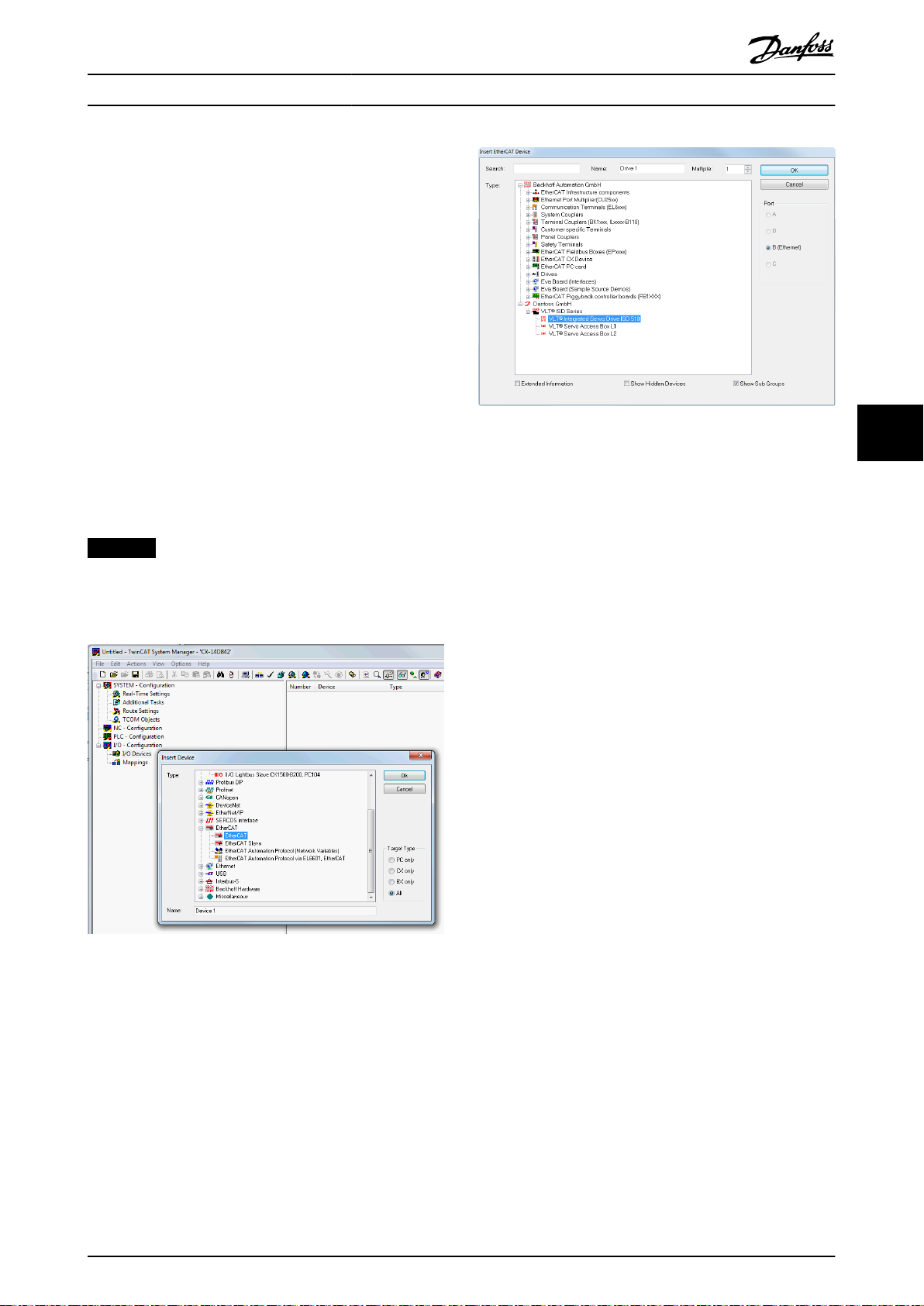
Commissioning Operating Instructions
6.
To add an SAB, right-click on Device1 (EtherCAT®)
and select Append Box….
7. In the Insert EtherCAT Device window, select
[Danfoss GmbH → VLT® ISD Series → VLT® Servo
Access Box L1] for Line 1 of the SAB (and/or VLT
Servo Access Box L2 for Line 2 of the SAB).
8. Click on OK.
9. To add a servo drive to line 1 of the SAB, right-
®
click on Box 1 (VLT
select Append Box...
10. In the Insert EtherCAT Device window, select
[Danfoss GmbH → VLT® ISD Series → VLT® ISD 510
Integrated Servo Drive].
11. Click on OK.
12. Answer the question if the drive is used as an NC
axis with No. If the drive should be used as an NC
axis, see chapter 6.4.2.3 Conguration as a
TwinCAT® NC Axis.
Servo Access Box L1) and
®
Illustration 6.12 Add an ISD 510 Servo Drive to the Project
6
6
NOTICE
Add 1 entry to the EtherCAT® master of the TwinCAT
System Manager for each physical servo drive and SAB.
Add the servo drive to the correct SAB line.
Illustration 6.11 Add an EtherCAT® Master to the Project
®
MG75K102 Danfoss A/S © 12/2015 All rights reserved. 51
Page 54

6
Commissioning
VLT® Integrated Servo Drive ISD® 510 System
1. Click on the ISD servo drive entry.
2. Select the Slots tab on the right side of the
window.
3. Remove the current PDO conguration by
selecting the entry Module 1 (CSV PDO) in the Slot
box.
4. Click on X.
5. Select Library PDO in the Module box.
6. Click on <.
Illustration 6.13 TwinCAT® System Manager after Appending
the PLC Project and Adding an SAB and 2 Servo Drives
I/O conguration and I/O mapping
When connecting >1 servo drive, connect port C (X2) of
the previous drive to port A (X1) of the next servo drive.
The SAB port assignment must also be followed, see
chapter 3.8.1 EtherCAT®. If the hardware set-up is already
present, the TwinCAT® System Manager Scan devices
function can be used to automatically add the connected
devices to the conguration in the correct order.
The servo drive has to be congured so that the PDO
mapping matches the requirements of the library. This is
done inside the TwinCAT® System Manager.
Illustration 6.14 ISD 510 Servo Drive with Correct I/O Congu-
ration
Attach the input and output variables of the PLC program
to the physical inputs and outputs of the device. This is
done inside the TwinCAT® System Manager so that the
library has access to all necessary objects.
1. Select Library TxPDO via menu [I/O-Conguration
→ I/O Devices → Device1 (EtherCAT®) → Box 1
(VLT® Servo Access Box L1) → Drive 2 (VLT® ISD
510 Integrated Servo Drive) → Module 1 (Library
PDO) → Library TxPDO].
2. Select all entries Lib pdo tx1 to Lib pdo tx9 on the
right side of the window (see Illustration 6.15).
3. Right-click and select Change Multi Link….
4. In the Attach Variable 36.0 Byte(s) (Input) window,
select [PLC-Conguration → MyFirstIsd510Project
→ Standard → .myAxis.TPDO].
Ensure that the Matching Size option is selected
in the Attach Variable window.
5. Click OK.
6. Click on Library RxPDO via menu [I/O-Congu-
ration → I/O Devices → Device1 (EtherCAT®) →
Box1 (VLT® Servo Access Box L1) → Drive2 (VLT
ISD 510 Integrated Servo Drive) → Module1
(Library PDO) → Library RxPDO].
7. Select all entries Lib pdo rx1 to Lib pdo rx9 on the
right side of the window.
®
52 Danfoss A/S © 12/2015 All rights reserved. MG75K102
Page 55

Commissioning Operating Instructions
8. Right-click and select Change Multi Link….
9. In the Attach Variable 36.0 Byte(s) (Output) window
select [PLC-Conguration → MyFirstIsd510Project
→ Standard → .myAxis.RPDO].
10. Click on OK.
11.
Right-click on WcState via [I/O-Conguration →
I/O Devices → Device1 (EtherCAT®) → Box1 (VLT
Servo Access Box L1) → Drive2 (VLT® ISD 510
Integrated Servo Drive) → WcState] and select
Change Link….
12. In the Attach Variable State (Input) window select
[PLC-Conguration → MyFirstIsd510Project →
Standard → .myAxis.WcState.
13. Click on OK.
14.
Right-click on State via
Devices → Device1 (EtherCAT®) → Box1 (VLT
Servo Access Box L1) → Drive2 (VLT® ISD 510
Integrated Servo Drive) → InfoData] and select
Change Link….
15. In the Attach Variable State (Input) window select
[PLC-Conguration → MyFirstIsd510Project →
Standard → .myAxis.State.
16. Click on OK.
17.
Right-click on netId via [I/O-Conguration → I/O
Devices → Device1 (EtherCAT®) → Box1 (VLT
Servo Access Box L1) → Drive2 (VLT® ISD 510
Integrated Servo Drive) → InfoData → AdsAddr]
and select Change Link….
18. In the Attach Variable netId (Input) window select
[PLC-Conguration → MyFirstIsd510Project →
Standard → .myAxis.AmsNetId.].
19. Click on OK.
20.
Right-click on port via [I/O-Conguration → I/O
Devices → Device1 (EtherCAT®) → Box1 (VLT
Servo Access Box L1) → Drive2 (VLT® ISD 510
Integrated Servo Drive) → InfoData → AdsAddr]
and select Change Link….
21. In the Attach Variable port (Input) window select
[PLC-Conguration → MyFirstIsd510Project →
Standard → .myAxis.NodeNumber.].
22. Click on OK.
[I/O-Conguration → I/O
®
®
®
®
Illustration 6.15 Attaching Inputs and Outputs to the Physical
Data Points
NOTICE
Repeat the steps 2–22 for Box 1 (VLT® Servo Access Box
L1) and the instance mySAB.
To transfer the mappings back to the PLC program, select
Activate Conguration… in menu item Actions.
After a rebuild in TwinCAT
conguration is according to Illustration 6.16 (here myAxis
and mySecondAxis are instances of AXIS_REF_ISD51x and
mySAB is an instance of SAB_REF). The concrete addresses
can be dierent.
Illustration 6.16 TwinCAT® Conguration: I/O Mapping of 2
Servo Drives and an SAB
®
PLC Control, the TwinCAT
®
6
6
MG75K102 Danfoss A/S © 12/2015 All rights reserved. 53
Page 56

Commissioning
VLT® Integrated Servo Drive ISD® 510 System
6
NOTICE
It is recommended to put the SAB to a separate SYNC
unit so that the communication to the SAB is not
interrupted if the U
switched o due to an error.
Cycle time settings
The minimum cycle time is 400 µs. The ISD 510 devices
can run EtherCAT® cycle times in multiples of 400 µs or
500 µs. The devices are automatically parameterized by the
PLC on start-up, depending on the EtherCAT® conguration
of the physical interface. The system base time can be
accessed by selecting
Settings] in the TwinCAT® System Manager. Multiples of this
base time can then be used as EtherCAT® cycle times.
supply to the servo drives is
AUX
[SYSTEM-Conguration → Real-Time
NOTICE
Set the task cycle time of the PLC program to be the
same as the EtherCAT® cycle time. Otherwise data can
get lost and performance is reduced.
Set the PLC cycle time in TwinCAT® PLC Control:
1. Double-click Task conguration in the Resources
tab.
2. Ensure that the PLC cycle time is the same as the
EtherCAT® cycle time.
Illustration 6.17 Task Conguration to Parameterize PLC Cycle
Time
NOTICE
After changing the task cycle time in TwinCAT® PLC
Control, carry out a ReScan of the PLC conguration
inside the TwinCAT® System Manager to update the
settings. Afterwards, activate the conguration in the
PLC.
6.4.2.3
Conguration as a TwinCAT® NC
Axis
It is possible to use the servo drives with the built-in NC
functionality of TwinCAT®. Everything that is related to the
SAB needs to be done as described in
®
chapter 6.4.2.2 Creating a TwinCAT
1. In addition to the Danfoss_VLT_ISD_510.lib le,
include the TcMC2.lib le (the
Danfoss_VLT_ISD_510.lib le is still needed for the
SAB to be operated).
2. Create 1 instance of AXIS_REF (instead of
AXIS_REF_ISD51x) for each servo drive that is used
as an NC axis.
3.
Append the PLC project into the TwinCAT
System Manager, import the devices and add
them to TwinCAT® as described in
chapter 6.4.2.2 Creating a TwinCAT
however in the last step, answer the question if
the servo drive is used as an NC axis with Yes.
Then an NC task is created automatically.
In the TwinCAT® System Manager a
ration needs to be selected for the drives that are used as
NC axes.
1. Depending on the mode of operation to be used,
select either the slot CSP PDO or CSV PDO. Per
default, CSV PDO is mapped and pre-selected. If
the drive should work with CSP PDO, the variables
need to be mapped:
1a In the Settings Tab of the NC Axis select
[NC-Conguration → NC-Task 1 SAF →
Axes → Axis 1]. Click on the Link To (all
Types)… button and select the desired
servo drive.
2. In the same tab, select the preferred Unit.
3. Depending on the selected Unit, adjust the
Scaling Factor for the axis encoder via menu [NC-
Conguration → NC-Task 1 SAF → Axes → Axis 1 →
Axis 1_Enc] in the Parameter tab.
Example: When the unit Degrees is selected, the
scaling factor is 360°/220 = 0.00034332275390625.
4. Set the Reference Velocity in the Parameter tab via
[NC-Conguration → NC-Task 1 SAF → Axes
menu
→ Axis 1 → Axis 1_Enc.
5. Set the Output Scaling Factor ( Velocity) to 125.
6. Test the functionality and the conguration in the
Online tab of the axis.
Project.
®
®
Project,
dierent I/O Congu-
54 Danfoss A/S © 12/2015 All rights reserved. MG75K102
Page 57

Commissioning Operating Instructions
6.4.2.4 Connecting to the PLC
Information on how to connect to the PLC can be found in
detail in the Beckho Information System (http://
infosys.beckho.com). Open the information system and go
to [TwinCAT 2 → TwinCAT System Manager → Operation →
Controls → Choose Target System].
6.4.3 Programming Guidelines
Recommendations for implementation:
Initialize parameters that usually do not change
•
only once at the beginning of the program. In
Automation Studio™, use the _INIT section.
Call up function blocks that provide status or
•
error information with Enable input at the
beginning of the program.
It is recommended to have 1 instance of the
•
function block MC_Power_ISD51x for every axis in
order to control its power stage. Call up this
function block in every PLC cycle.
It is recommended to have 1 instance of the
•
function block DD_Power_SAB for every SAB to
control the DC-link voltage on the output lines.
Call up this function block in every PLC cycle.
Call up function blocks that execute (motion)
•
commands at the end of the program.
Do not use any POUs of the library (folder)
•
Intern_51x.
Do not change the reference to the axis on a
•
function block while it is busy.
6
6
Illustration 6.18 shows sample code for TwinCAT®.
Illustration 6.18 Sample Code for TwinCAT
®
NOTICE
The full parameter list can be found in the VLT
Integrated Servo Drive ISD® 510 System Programming
Guide.
®
MG75K102 Danfoss A/S © 12/2015 All rights reserved. 55
Page 58

Commissioning
VLT® Integrated Servo Drive ISD® 510 System
6
6.5 ISD Toolbox
6.5.1 Overview
The ISD Toolbox is a standalone PC software designed by
Danfoss. It is used for parameterization and diagnostics of
the servo drives and the SAB. It is also possible to operate
the devices in a non-productive environment. The ISD
Toolbox contains several functionalities, called sub-tools,
which in turn provide various functionalities.
The most important sub-tools are:
Scope for visualization of the tracing functionality
•
of the servo drives and SAB.
Parameter list for reading/writing parameters.
•
Firmware update
•
Drive control/SAB control to operate the servo
•
drives and/or SAB for testing purposes.
CAM editor for designing CAM proles for the
•
servo drives.
The detailed description of the ISD Toolbox functionality
and the full list of parameters can be found in the VLT
Integrated Servo Drive ISD® 510 System Programming Guide.
®
6.5.2 System Requirements
To install the ISD Toolbox software, the PC must meet the
following requirements:
Supported hardware platforms: 32-bit, 64-bit.
•
Supported operating systems: Windows XP
•
Service Pack 3, Windows 7, Windows 8.1.
.NET framework version: 3.5 Service Pack 1.
•
Minimum hardware requirements: 512 MB RAM,
•
Intel Pentium 4 with 2.6 GHz or equivalent, 20 MB
hard disk space.
Recommended hardware requirements: Minimum
•
1 GB RAM, Intel Core i5/i7 or compatible.
6.5.3 Installation
Administrator rights are required for installing the software
with the Windows operating system. Contact your administrator if necessary.
4. Follow the on-screen instructions to complete the
installation process.
6.5.4 ISD Toolbox Communication
This chapter describes the Ethernet specic network
interface settings needed by the ISD Toolbox. There are 2
basic communication methods: direct communication and
indirect communication. Their particular network settings
are described in the respective sections.
Read and perform the steps with care - incorrect network
congurations can lead to loss of connectivity of a network
interface.
Firewall
Depending on the rewall settings and the eldbus used,
the messages sent and received by the ISD Toolbox may
be blocked by the rewall on the ISD Toolbox host system.
This may lead to a loss of communication and the inability
to communicate with the devices on the eldbus.
Therefore, ensure that the ISD Toolbox is allowed to
communicate through the rewall on the ISD Toolbox host
system. Read and perform the steps with care - inappropriate changes to rewall settings may lead to security
issues.
NOTICE
When using a dedicated network interface, the ISD
Toolbox should be allowed to communicate specically
through this network interface.
Indirect communication
Communication between ISD 510 devices and the ISD
Toolbox through a PLC is called indirect communication.
Between the PLC and the ISD 510 devices there is
Ethernet-based eldbus communication (marked A in
Illustration 6.19), whereas there is non-eldbus communi-
cation between the PLC and the ISD Toolbox host system
(marked B in Illustration 6.19).
In the scenario in Illustration 6.19, the PLC has the master
function and uses cyclic communication with the devices.
Therefore, not all functionalities of the ISD Toolbox, for
example the drive control, can be used. The restrictions
when using indirect communication are detailed in the
VLT® Integrated Servo Drives ISD® 510 Programming Guide.
1. Check that your system meets the system
requirements as described in chapter 6.5.2 System
Requirements.
2. Download the ISD Toolbox installation le (http://
vlt-drives.danfoss.com/products/engineeringsoftware/software-download/).
3. Right-click on the .exe le and select Run as
administrator.
56 Danfoss A/S © 12/2015 All rights reserved. MG75K102
Page 59

130BE309.10
Aux 1
Aux 2
Safe
1
Safe
2
A
2 n
SAB
1
B
PLC
. . .
Aux 1
Aux 2
Safe 1
Safe
2
A
2 n
SAB
1
B
. . .
130BE310.10
Commissioning Operating Instructions
A Fieldbus
B General purpose network
Illustration 6.19 Logical View of Indirect Ethernet-based
Fieldbus Communication (Communication via PLC)
NOTICE
The logical view only shows the connectivity from a
high-level software perspective and does not reect the
actual physical topology of the network.
Direct communication
For Ethernet-based eldbus communication (direct
communication), the ISD Toolbox must use a dedicated
network interface on the ISD Toolbox host system. This
network interface should not simultaneously be used for
any other communication.
NOTICE
The logical view only shows the connectivity from a
high-level software perspective and does not reect the
actual physical topology of the network.
6.5.4.1 Network Settings for Indirect
Communication
Any network interface can be used to communicate
through a PLC and a dedicated network interface is not
needed.
When establishing the communication through a PLC, the
ISD Toolbox congures a routing table using the selected
Network Address Translation (NAT). Adding a route to the
Windows routing table requires administrator privileges.
Therefore, administrator credentials may be requested
when initializing the connection.
Carry out the following steps to enable indirect communication.
Disable IPv6 on the network interfaces used for communication on the PC:
1. Open the Network and Sharing Center.
2. Select Change adapter settings.
3. Right-click on the network interface used for
eldbus communication and select Properties.
4. If the TCP/IPv6 is available for the network
interface, disable it.
6
6
A Fieldbus
B General purpose network
Illustration 6.20 Logical View of Direct Ethernet-based Fieldbus
Communication
Illustration 6.21 Local Area Connection Properties
MG75K102 Danfoss A/S © 12/2015 All rights reserved. 57
Page 60

6
Commissioning
VLT® Integrated Servo Drive ISD® 510 System
NOTICE
When observing the network packets via Wireshark®,
checksum ooading often causes confusion as the
network packets to be transmitted are handed over to
Wireshark® before the checksums have been calculated.
Wireshark® shows these empty checksums as invalid,
even though the packets contain valid checksums when
they leave the network hardware later.
Use 1 of these 2 methods to avoid this checksum
ooading problem:
Turn o the checksum ooading in the network
•
driver if possible.
Turn o the checksum validation of the specic
•
protocol in the Wireshark® preferences.
Additional settings for indirect communication over
EtherCAT
Set the IP address of the EtherCAT® Master:
Activate IP routing on the EtherCAT® Master:
®
1.
Open the TwinCAT
2.
Select [I/O-Conguration → I/O Devices → Device1
(EtherCAT®)] and check the IP-address in the
Adapter tab.
The IP-address of the PLCs network adapter may
not be a link-local address (so not in the range of
169.254.0.1 to 169.254.255.254).
3. If necessary, change the IP-address inside the IPv4
Protocol properties according to the given
operating system. This can be done on the
controller locally or via Remote Desktop.
®
System Manager.
NOTICE
The procedure described here may vary depending on
the type of PLC and operating system installed.
1.
Open the TwinCAT® System Manager.
2. Click on Advanced Settings… under [I/O-Congu-
ration → I/O Devices → Device1 (EtherCAT®)] in
the EtherCAT tab.
3. Select EoE Support in the Advanced Settings
window.
4. Enable Connect to TCP/IP Stack in the Windows
Network section.
5. Enable IP Enable Router in the Windows IP Routing
section.
6. Reboot the PLC for the changes to take eect.
®
Set the IP address of the EtherCAT
SAB):
1.
Open the TwinCAT® System Manager.
2. Click on Advanced Settings… under [I/O-Congu-
ration → I/O Devices → Device1 (EtherCAT®) → Box
1 (VLT® Servo Access Box L1 → Drive 2 (VLT
Integrated Servo Drive ISD 510)] in the EtherCAT
tab.
3.
Select [Mailbox → EoE] in the Advanced Settings
window.
4. Enable Virtual Ethernet Port and enter a valid IP
Address.
5. Each slave in the conguration requires an IPaddress. This address is reassigned with every
transition from INIT to Pre-Operational state of the
slave state machine. The IP communication of the
slaves is deactivated per default.
slave (servo drive or
®
NOTICE
The last number of the IP address is the ID that is used
in the ISD Toolbox to identify the device.
6.5.4.2 Network Settings for Direct
Communication with Ethernet
POWERLINK
Disable all network protocols except TCP/IPv4 on the
network interface used for direct Ethernet POWERLINK
communication. This prevents other PC software or the
operating system using this network interface for other
tasks, such as le and printer sharing and network
discovery. Disabling these protocols reduces the number of
non-relevant packets sent over the network interface and
thus reduces the overall network load.
How to disable all unused protocols on the network
interface on the PC:
1. Open the Network and Sharing Center.
2. On the left, click on Change adapter settings.
3. Right-click on the network interface used for
eldbus communication and select Properties.
4. Uncheck all checkboxes except the one for
Internet Protocol Version 4 (TCP/IPv4).
®
®
58 Danfoss A/S © 12/2015 All rights reserved. MG75K102
Page 61

Commissioning Operating Instructions
6
6
Illustration 6.22 Local Area Connection 2 Properties
Disable the IPv4 Checksum ooad on the network
interfaces as described in chapter 6.5.4.1 Network Settings
for Indirect Communication.
How to set the correct Ethernet POWERLINK® master IP
address:
1. Open the Network and Sharing Center.
2. On the left, click on Change adapter settings.
3. Right-click on the network interface used for
eldbus communication and select Properties.
4. Click on Internet Protocol Version 4 (TCP/IPv4) (the
checkbox must be checked) and then click on
Properties.
5. Select Use the following IP address and use
192.168.100.240 as the IP address and
255.255.255.0 as the subnet mask. Leave all other
elds empty.
Illustration 6.23 Internet Protocol Version 4 (TCP/IPv4)
Properties
6.5.4.3 Network Settings for Direct
Communication with EtherCAT
No EtherCAT®-specic network interface conguration
needs to be performed on the ISD Toolbox host PC.
®
MG75K102 Danfoss A/S © 12/2015 All rights reserved. 59
Page 62

130BE311.10
1
2
3
4
5
7
8
9
6
6
Commissioning
VLT® Integrated Servo Drive ISD® 510 System
6.5.5 ISD Toolbox Commissioning
STEP 1: Open the main window
The Main Window is the basis for all ISD Toolbox functionalities. It consists of the following components:
Illustration 6.24 Main Window
60 Danfoss A/S © 12/2015 All rights reserved. MG75K102
Page 63

Commissioning Operating Instructions
1 Menu bar Contains the general functionalities for saving and loading projects, managing connections,
showing and changing settings, managing open sub-tools, and showing help contents.
2 Tool bar Contains shortcuts for saving and loading projects, connecting to and disconnecting from
networks, automatic searching for online devices, or manually adding devices.
3 Online/Oine status and state
information
4 Available sub-tools A sub-tool is opened by double-clicking the left mouse button on its name in the Device
5 Device environment The Device Environment section of the Main Window lists all logical devices managed by the
6 Workspace This is the space for hosting the sub-tools and its size depends on the Main Window size. The
7 Watchlist window Evaluates the parameter values of 1 or more devices by cyclically reading them from the
8 Output window Shows operating information, warnings, and errors. Depending on the user settings, shows
9 Status strip Shows the communication state of the ISD Toolbox. If connected to a network, it shows the
Online devices are indicated by a glowing light bulb next to the device ID.
•
- An online device is a logical device for which a physical device exists, which the
ISD Toolbox is currently connected to.
- The color indicates the state of the device and is device–specic.
Oine devices are indicated by a gray light bulb next to the device ID.
•
- An oine device is a logical device without a corresponding physical device. An
oine device can represent a saved device conguration or state, for example for
oine analysis or troubleshooting. It also contains pre-congured parameter
values to be written to a physical device.
Environment, or by selecting the entry and pressing the Enter key on the keyboard.
ISD Toolbox, visualizes their states, and serves as the user interface for accessing the device
functionalities.
The Device Environment window lists all available sub-tools for each added device. See the
VLT® Integrated Servo Drive ISD® 510 System Programming Guide for further information on the
sub-tools.
sub-tools can be maximized, minimized, horizontally or vertically aligned, or cascaded.
devices. Allows parameter values to be logged and saved to a text le. It is also possible to
modify/write values in the watchlist.
messages of up to 3 dierent logging levels (high, medium, and low). Used for showing
advanced error and warning information.
used hardware interface (for example, network adapter) and the network name.
6
6
Table 6.1 Legend to Illustration 6.24
STEP 2: Connect to network
NOTICE
Pre-congure the appropriate communication settings to
connect to a network. See chapter 6.5.4 ISD Toolbox
Communication for further information.
1. In the Main Window toolbar, click on the Connect
to bus icon to open the Connect to Network
window.
2. Select the eldbus type and the network
interface to connect to.
3. Click on OK to connect.
4. Verify that the connection is successful by
checking the status strip in the Main Window.
Illustration 6.25 Connect To Network Window (Ethernet
POWERLINK®)
MG75K102 Danfoss A/S © 12/2015 All rights reserved. 61
Page 64

Commissioning
VLT® Integrated Servo Drive ISD® 510 System
6
STEP 3: Scan for devices
1. After verifying that the ISD Toolbox is connected
to the selected network, click on the Scan for
Devices icon in the toolbar to trigger the device
scan procedure.
NOTICE
If connected to an Ethernet POWERLINK® network in
cyclic mode, select the scan range (minimum and
maximum IDs) in the next window to reduce the time
needed for scanning. In all other cases, the complete ID
range is scanned.
2. When the scan is complete, a list of available
devices is showed in the Select Devices window.
Select which devices to add to the Device
Environment and click on OK.
3. All selected devices appear in the Device
Environment window and automatically go online
(indicated by a glowing light bulb next to each
device name).
NOTICE
See the VLT® Integrated Servo Drive ISD® 510 System
Programming Guide for further information on the ISD
Toolbox software.
6.6.2 Simple Programming Template
Automation Studio™
Detailed information on how to open the sample project
within the ISD package in Automation Studio™ can be
found in the Automation Studio™ Help. Open the B&R
Help Explorer and go to [Programming → Examples →
Adding sample programs] and follow the instructions for
library samples.
TwinCAT
A basic sample PLC application for starting up the ISD 510
servo system with 1 SAB and 2 axes is provided. The
project ISD_System_SampleProject can be downloaded from
the Danfoss website.
®
6.6 Motion Library
6.6.1 Function Blocks
The PLC library provides function blocks that support the
functionality of the ISD devices and comply with this
standard:
PLCopen® Technical Specication Function blocks for
motion control (Formerly Part 1 and Part 2) Version 2.0
March 17, 2011.
Additionally,
functionality that is not described by PLCopen®.
The following PLCopen® characteristics apply to all
function blocks:
•
•
•
specic ISD function blocks provide the
Commanding (using the inputs)
Signaling (behaviour of the outputs)
General calling conventions
NOTICE
See the VLT® Integrated Servo Drive ISD® 510 System
Programming Guide for further information on the
available function blocks and their behavior.
62 Danfoss A/S © 12/2015 All rights reserved. MG75K102
Page 65
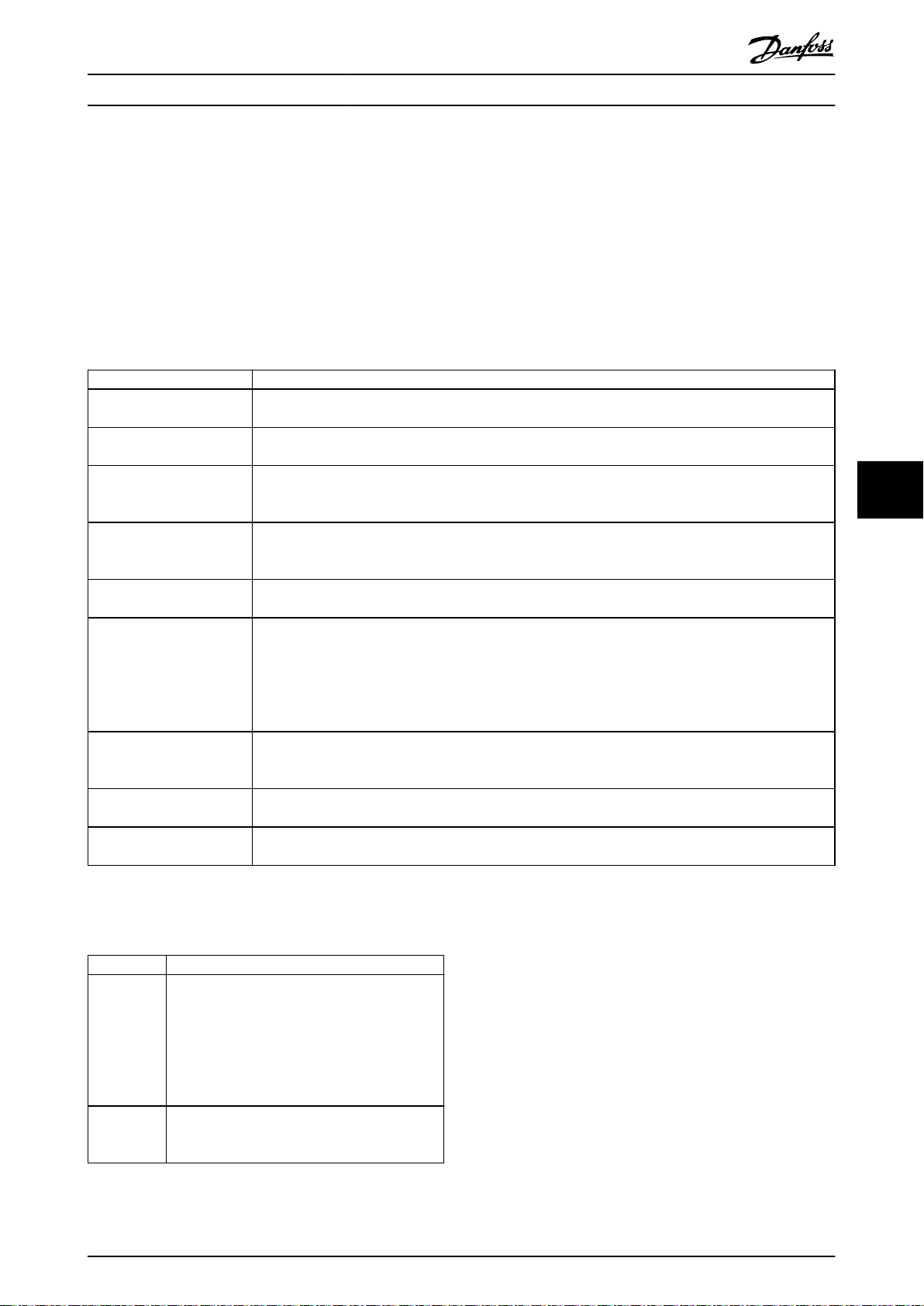
Operation Operating Instructions
7 Operation
7.1 Operating Modes
The servo drive implements several modes of operation. The behavior of the servo drive depends on the activated mode of
operation. It is possible to switch between the modes while the servo drive is enabled. The supported modes of operation
are according to CANopen® CiA DS 402 and there are also ISD-specic modes of operation. All supported modes of
operation are available for EtherCAT® and Ethernet POWERLINK®. The various modes of operation are described in detail in
the VLT® Integrated Servo Drive ISD® 510 System Programming Guide.
Mode Description
ISD Inertia measurement
mode
Prole velocity mode In prole velocity mode, the servo drive is operated under velocity control and executes a movement with
Prole position mode In prole position mode, the servo drive is operated under position control and executes absolute and
Prole torque mode In prole torque mode, the servo drive is operated under torque control and executes a movement with
Homing mode In homing mode, the application reference position of the servo drive can be set. Several homing methods,
CAM mode In CAM mode, the servo drive executes a synchronized movement based on a master axis. The synchroni-
Gear mode In gear mode, the servo drive executes a synchronized movement based on a master axis by using a gear
Cyclic synchronous position
mode
Cyclic synchronous velocity
mode
This mode measures the inertia of an axis. It is used to measure the inertia of the servo drive and the
external load, and to optimize the control loop settings. The friction eects are eliminated automatically.
constant speed. Additional parameters, such as acceleration and deceleration, can be parameterized.
relative movements. Additional parameters, such as velocity, acceleration, and deceleration, can be parame-
terized.
constant torque. Linear ramps are used. Additional parameters, such as torque ramp and maximum
velocity, can be parameterized.
such as homing on actual position, homing on block, limit switch, or home switch are available.
zation is done by means of a CAM prole that contains slave positions corresponding to master positions.
CAMs can be designed graphically with the ISD Toolbox software, or can be parameterized via the PLC. The
guide value can be provided by an external encoder, virtual axis, or the position of another axis. The
dierent CAM prole types are described in the VLT® Integrated Servo Drive ISD® 510 System Programming
Guide.
ratio between the master and the slave position. The guide value can be provided by an external encoder,
virtual axis, or the position of another axis.
In cyclic synchronous position mode, the trajectory generator of the position is located in the control
device, not in the servo drive.
In cyclic synchronous velocity mode, the trajectory generator of the velocity is located in the control
device, not in the servo drive.
7 7
Table 7.1 Operating Modes
7.1.1 Motion Functions
Function Description
Digital CAM
switch
ISD touch
probe
Table 7.2 Motion Functions
MG75K102 Danfoss A/S © 12/2015 All rights reserved. 63
This functionality controls whether the digital
output is enabled or disabled, depending on the
axis position. It performs a function comparable
to switches on a motor shaft. Forward and
backward movements of the axis position are
allowed. On and o compensation and hysteresis
can be parameterized.
This functionality stores the position actual value
after a rising or falling edge at the congured
digital input.
7.2 Operating Status Indicators
The operating status of the servo drive and SAB is
indicated via the LEDs on each device.
Page 66

DRIVE STAT X1
X2
X3
NET STAT
LINK/ACT
DRIVE STAT X1
X2NET STAT
LINK/ACT
Advanced Standard
130BE677.10
Aux 1
Aux 2
Safe 1
Safe 2
130BE733.10
Operation
VLT® Integrated Servo Drive ISD® 510 System
7.2.1 Operating LEDs on the Servo Drive
Illustration 7.1 shows the operating LEDs on the servo
drive.
Illustration 7.1 Operating LEDs on the Servo Drive
77
LED Color Flash status Description
DRIVE
Green On Servo drive is in state
STAT
Flashing Auxiliary voltage is
Red On Servo drive is in Fault
Flashing DC-link voltage is not
NET
Green/
Fieldbus dependent Network status of the
STAT
red
Link/A
Green – Link/activity status of
CT X1
On Ethernet link
Flashing Ethernet link
O No link.
Link/A
Green – Link/activity status of
CT X2
On Ethernet link
Flashing Ethernet link
O No link.
Operation enabled.
applied.
or Fault reaction active
state.
applied.
device (see
corresponding eldbus
standard).
Hybrid In (X1)
established.
established and active.
Hybrid Out (X2)
established.
established and active.
LED Color Flash status Description
Link/A
Green – Link/activity status of
CT
1)
X3
Table 7.3 Legend to Illustration 7.1
1) Advanced version only
On Ethernet link
Flashing Ethernet link
O No link.
the Ethernet port (X3).
established.
established and active.
7.2.2 Operating LEDs on the Servo Access
Box
Illustration 7.2 Operating LEDs on the SAB
LED Color Flash status Description
Aux 1 Green – State of the auxiliary
voltage on line 1.
On Statemachine is in
state Standby, Power
up, or Operation
enabled. Auxiliary
voltage is applied to
the output connectors
on line 1.
O Statemachine is in
state U
Fault. Auxiliary voltage
is not applied to line 1.
disabled or
AUX
64 Danfoss A/S © 12/2015 All rights reserved. MG75K102
Page 67

Operation Operating Instructions
LED Color Flash status Description
Aux 2 Green – State of the auxiliary
voltage on line 2.
On Statemachine is in
state Standby, Power
up, or Operation
enabled. Auxiliary
voltage is applied to
the output connectors
on line 2.
O Statemachine is in
state U
Fault. Auxiliary voltage
is not applied to line 2.
Safe 1 Green On 24 V for STO is present
on line 1.
O 24 V for STO is not
present on line 1.
Safe 2 Green On 24 V for STO is present
on line 2.
O 24 V for STO is not
present on line 2.
SAB
Green On SAB is in state
STAT
Flashing Auxiliary voltage is
O No auxiliary voltage is
Red On The SAB is in state
Flashing Mains is not applied at
NET
Green/
Fieldbus dependent. Network status of the
STAT
red
Link/A
Green – Link/activity status of
CT X1
On Ethernet link
Flashing Ethernet link
O No link.
Link/A
Green – Link/activity status of
CT X2
On Ethernet link
Flashing Ethernet link
O No link.
Operation enabled.
applied at the input.
applied at the input.
Fault.
the input.
device (see
corresponding eldbus
standard).
In.
established.
established and active.
Out.
established.
established and active.
disabled or
AUX
LED Color Flash status Description
Link/A
Green – Link/activity status of
CT X3
On Ethernet link
Flashing Ethernet link
O No link.
Link/A
Green – Link/activity status of
CT X4
On Ethernet link
Flashing Ethernet link
O No link.
Table 7.4 Legend to Illustration 7.2
line 1.
established.
established and active.
line 2.
established.
established and active.
7 7
MG75K102 Danfoss A/S © 12/2015 All rights reserved. 65
Page 68

ISD Safety Concept
8 ISD Safety Concept
VLT® Integrated Servo Drive ISD® 510 System
8.1 Applied Standards and Compliance
Use of the STO function requires that all provisions for
safety, including relevant laws, regulations, and guidelines,
are satised.
The integrated STO function complies with the following
standards:
EN 60204-1: 2006 Stop Category 0 – uncontrolled
•
stop
IEC/EN 61508: 2010 SIL 2
•
IEC/EN 61800-5-2: 2007 SIL 2
•
IEC/EN 62061: 2005 SIL CL2
•
EN ISO 13849-1: 2008 Category 3 PL d
•
The ISD 510 servo system has been tested for higher EMC
immunity as described in IEC/EN 61326-3-1.
88
8.2 Abbreviations and Conventions
Abbreviation Reference Description
Cat. EN ISO
13849-1
DC – Diagnostic coverage
FIT – Failure in time
H EN IEC 61508 Hardware fault tolerance
MTTFd EN ISO
13849-1
PFH EN IEC 61508 Probability of dangerous failures
PFD EN IEC 61508 Average probability of failure on
PL EN ISO
13849-1
Category, level B, 1–4
Failure rate: 1E-9/hour
H = n means that n + 1 faults may
lead to a loss of the safety
function.
Mean time to failure – dangerous
Unit: years
per hour
Take this value into account if the
safety device is operated in high
demand mode or in continuous
operating mode, where the
frequency of demands for
operation made on a safety-related
system occurs more than once per
year.
demand.
This value is used for low demand
operation.
Performance level
A discrete level used to specify the
capability of safety-related parts of
a system to perform safety-
oriented functions under
foreseeable conditions. Levels: a–e.
Abbreviation Reference Description
SFF EN IEC 61508 Safe Failure Fraction [%]
Proportion of safe failures and
detected dangerous failures of a
safety function or a subsystem as a
percentage of all possible failures.
SIL EN IEC 61508
EN IEC 62061
STO EN IEC
61800-5-2
SS1 EN IEC
61800-5-2
SRECS EN IEC 62061 Safety-related electrical control
SRP/CS EN ISO
13849-1
PDS/SR EN IEC
61800-5-2
Table 8.1 Abbreviations and Conventions
Safety Integrity Level
Safe Torque O
Safe stop 1
system
Safety-related parts of control
systems
Power drive system (safety-related)
8.3 Qualied Personnel for Working with
the STO Function
The STO function may only be installed, programmed,
commissioned, maintained, and decommissioned by
qualied personnel. Qualied personnel for the STO
function are qualied electrical engineers, or persons who
have received training from qualied electrical engineers
and are suitably experienced to operate devices, systems,
plant, and machinery in accordance with the general
standards and guidelines for safety technology.
Furthermore they must:
Be familiar with the basic regulations concerning
•
health and safety/accident prevention.
Have read and understood the safety guidelines
•
given in this manual.
Have a good knowledge of the generic and
•
specialist standards applicable to the specic
application.
Users of power drive systems (safety-related) (PDS(SR)) are
responsible for:
Hazard and risk analysis of the application.
•
Identifying safety functions required and
•
allocating SIL or PLr to each of the functions,
other subsystems, and the validity of signals and
commands from them.
Designing appropriate safety-related control
•
systems (hardware, software, parameterization,
and so on).
66 Danfoss A/S © 12/2015 All rights reserved. MG75K102
Page 69

ISD Safety Concept Operating Instructions
Protective measures
Install the ISD 510 servo system components with
•
a protective rating of less than IP54 in an IP54
cabinet as per IEC 60529 or in an equivalent
environment. In special applications, higher IP
protection may be necessary.
If external inuences can inuence the motor
•
axis, for example suspended loads, use additional
measures, such as a safety holding brake, to
eliminate hazards.
8.4 Safety Precautions
NOTICE
After installing the STO function, perform a commissioning test as described in chapter 8.9 Commissioning
Test. A passed commissioning test is mandatory after
initial installation and after each change to the safety
installation.
WARNING
UNCONTROLLED MOVEMENT
External forces on the motor could cause an uncontrolled
and hazardous movement that could result in death or
serious injury.
Equip the motor with additional measures for
•
preventing uncontrolled and hazardous
movement, for example mechanical brakes.
WARNING
RISK OF ELECTRICAL SHOCK
The STO function does not isolate mains voltage to the
ISD 510 servo system or auxiliary circuits. Only perform
work on electrical parts of the ISD510 system or the
servo drive after isolating the mains voltage supply and
waiting the length of time specied in chapter 2 Safety.
Failure to isolate the mains voltage supply and waiting
the time specied could result in death or serious injury.
Do not use the STO function to stop a running
•
ISD 510 servo system in normal operation.
When using the STO function the servo drive
coasts to stop. Depending on the application, a
mechanical brake may be required.
Use the STO function when performing
•
mechanical work on the ISD 510 servo system
or aected area of a machine. The STO function
does not provide electrical safety and must not
be used as a control to start and/or stop the
ISD 510 servo system.
NOTICE
The ISD 510 servo system does not implement a manual
reset function as required by ISO 13849-1. The standard
failure reset from the PLC cannot be used for this
purpose.
For automatic restart without manual reset, observe the
requirements detailed in paragraph 6.3.3.2.5 of ISO
12100:2010 or equivalent standard.
8 8
WARNING
RISK OF ELECTRICAL SHOCK
The STO function itself does not supply electrical safety
and is not sucient to implement the Emergency-O
function as dened by EN 60204-1, resulting in risk of
death or serious injury.
Ensure electrical isolation for Emergency-O, for
•
example by switching o the mains via an
additional contactor.
WARNING
RISK OF RESIDUAL ROTATION
Due to failures in the power semiconductor of the drive,
a residual rotation can result from a fault that could
result in death or serious injury. The rotation can be
calculated to angle = 360°/(number of poles).
Take this residual rotation into consideration
•
and ensure that it does not pose a safety risk.
NOTICE
Take measures to ensure that common mode voltage
disturbances, as described in EN/IEC 61000-4-16, do not
occur in the installation. This can be done, for example,
by installing according to the requirements of EN/
IEC 60204-1.
NOTICE
Carry out a risk assessment to select the correct stop
category for each stop function in accordance with
EN 60204-1.
MG75K102 Danfoss A/S © 12/2015 All rights reserved. 67
Page 70

130BE690.10
SAB
STO 1 IN: + STO
STO 1 IN: – STO
STO 2 IN: + STO
STO 2 IN: – STO
ISD Safety Concept
VLT® Integrated Servo Drive ISD® 510 System
NOTICE
When designing the machine application, consider
timing and distance for coast to stop (Stop Category 2 or
STO). See EN 60204-1 for further information.
NOTICE
All signals connected to the STO must be supplied by a
SELV or PELV supply.
8.5 Functional Description
The STO function in the ISD 510 servo system features a
separate STO function for each line of servo drives in daisychain format. The function is activated by inputs on the
SAB. Using the STO function activates the STO for all servo
drives on that line. Once the STO is activated, no torque is
generated on the axes. Reset of the safety function and
diagnostics can be carried out via the PLC.
8.6 Installation
88
Install the ISD 510 servo system as described in
chapter 4 Mechanical Installation and chapter 5 Electrical
Installation. Only Danfoss cables may be used for the
installation of the servo system, however cables from other
suppliers may be used for the user connection to the STO
terminals (STO 1 IN and STO 2 IN) on the SAB.
NOTICE
If the application does not require the Safe Torque O
(STO) functionality, build a bridge by connecting +24 V
from the connector STO 1 IN: +24V to STO 1 IN: +STO,
and from STO 1 IN: –24 V to STO 1 IN: –STO. Repeat this
process for STO line 2 if used.
Safety relays that have a plus and minus switching output
signal can be directly connected to the ISD 510 servo
system to activate STO (see Illustration 8.1). Route the wires
for STO 1 and STO 2 separately and not in a single
multicore cable.
Signals with test pulses must not have test pulses of >1
ms. Longer pulses may lead to reduced availability of the
servo system.
The external supply must be a SELV/PELV supply.
8.7 Operation of the ISD Safety Concept
This chapter details the basic STO signals. Some of the
signals can be reached in several ways, however only
access via eldbus is described here. See the VLT
Integrated Servo Drive ISD® 510 System Programming Guide
for further information.
The STO function does not require any parameterization
and is always enabled. To disable the function
permanently, connect the STO inputs directly to the 24 V
outputs STO 1 IN: 24 V or STO 2 IN: 24 V on the SAB.
The ISD 510 servo drive provides STO status signals via the
eldbus.
For general information on how to access and map data
objects, see the VLT® Integrated Servo Drive ISD® 510 System
Programming Guide.
Danfoss provides a library for ISD 510 to simplify the use
of the eldbus functions. See the VLT® Integrated Servo
Drive ISD® 510 System Programming Guide for further
information.
®
8.7.1 Statusword
The statusword in 0x6041 provides the STO status in bit 14.
The bit is set to 1 if STO is active and 0 if STO is
deactivated. All servo drives on each STO line must display
the same information in this bit. Carry out a check via the
PLC to compare the STO status of all servo drives on each
line.
If STO is activated when the servo drive is disabled, and no
attempt is made to enable the servo drive while STO is
active, it is not necessary to reset the STO function after
reapplying supply to the STO terminals.
If STO is activated when the servo drive is enabled, an
error code is issued (see chapter 8.7.2 Error Codes).
Illustration 8.1 Safety Relay with Plus and Minus Switching
Output
68 Danfoss A/S © 12/2015 All rights reserved. MG75K102
Page 71

ISD Safety Concept Operating Instructions
8.7.2 Error Codes
If bit 3 of the statusword is set, this indicates any faults
that occur on the servo drive. If the fault occurred because
of the STO circuit, the cause of the fault can be found in
object 0x603F.
Error
code
0xFF80 Fault STO activated while the servo
0xFF81 Safety
0xFF85 Safety
Table 8.2 Error Codes
Classi-
cation
fault
fault
Description Reset
Reset via the
drive was enabled, or an
attempt to enable the servo
drive was made while STO
was active.
Servo drive internal diagnostic
fault.
Internal STO supply on the
power card is not within
limits.
PLC.
Carry out a
power cycle.
Carry out a
power cycle.
8.9 Commissioning Test
Error code 0xFF80 can be a normal status of the
application. In this case, the servo drive requires a reset
signal from the PLC. To use the STO function in an
application that requires a control guard (see ISO 12100 for
details), this reset information can be given automatically
by the PLC.
Error code 0xFF81 means that there is a fault on the servo
drive that can only be reset by carrying out a power cycle.
Complete the commissioning test as described in
chapter 8.9 Commissioning Test after the power cycle.
Operation of the ISD 510 servo system can only be
resumed if the test is completed successfully. If error code
0xFF81 or 0xFF85 is issued again, contact Danfoss Service.
8.8 Fault Reset
Change bit 7 of the controlword from 0 to 1 to reset faults.
See the VLT® Integrated Servo Drive ISD® 510 System
Programming Guide for further information.
8 8
NOTICE
Perform a commissioning test after installation of the STO function, after every change to the installed function, or after
a safety fault (described in chapter 8.7.2 Error Codes). Perform the test for each STO line.
There are 2 ways to implement the commissioning test depending on the method used to program the PLC, however the
steps of the test are the same:
Using the Danfoss Library or the TwinCAT® Library.
•
Bit-wise readout of the status.
•
Commissioning test using libraries
Depending on the application, 1 or both of the following libraries are required to program the commissioning test:
Danfoss Library
•
- MC_ReadAxisInfo_ISD51x
- MC_ReadStatus_ISD51x
- MC_ReadAxisError_ISD51x
- MC_Reset_ISD51x
TwinCAT® Library
•
- MC_ReadStatus
- MC_ReadAxisError
- MC_Reset
Test steps Reason for the test step Expected result for Danfoss
library
1 Run the application (all the
servo drives are enabled).
2 Stop the application. – All servo drives are at speed 0
3 Disable all the servo drives. – All servo drives are disabled. All servo drives are disabled.
MG75K102 Danfoss A/S © 12/2015 All rights reserved. 69
Check that the application can
run.
Application runs as expected. Application runs as expected.
RPM.
Expected result for TwinCAT
library
All servo drives are at speed 0
RPM.
®
Page 72

ISD Safety Concept
VLT® Integrated Servo Drive ISD® 510 System
Test steps Reason for the test step Expected result for Danfoss
library
4 Enable STO. Check that STO can be
activated without error.
5 Disable STO. Check that STO can be
deactivated without error. No
reset is required.
6 Run the application (all the
servo drives are enabled).
7 Enable STO. Check that errors are
– Application runs as expected. Application runs as expected.
generated correctly when STO
is activated while the servo
drives are running.
88
8 Try to run the application
(enable 1 or more servo
drives).
9 Disable STO. Check that the STO start is
10 Try to run the application
(enable 1 or more servo
drives).
11 Send a reset signal via
MC_Reset(_ISD51x).
12 Try to run the application (all
servo drives are enabled).
Checks that the STO function
is working correctly.
still inhibited by the error
signal.
Check whether reset is
required.
– MC_ReadAxisInfo_ISD51x output
– Application runs as expected. Application runs as expected.
MC_ReadAxisInfo_ISD51x output
SafeTorqueO = True for all
servo drives on the
corresponding line.
MC_ReadAxisInfo_ISD51x output
SafeTorqueO = False for all
servo drives on the
corresponding line.
Motors are torque free. Motors
coast and stop after some
time.
MC_ReadAxisInfo_ISD51x output
SafeTorqueO = True
and
MC_ReadStatus_ISD51x output
ErrorStop = True
and
MC_ReadAxisError_ISD51x
output AxisErrorID = 0xFF80 on
all enabled servo drives.
Application does not run. Application does not run.
MC_ReadAxisInfo_ISD51x output
SafeTorqueO = False
and
MC_ReadStatus_ISD51x output
ErrorStop = True
Application does not run. Application does not run.
SafeTorqueO = False
and
MC_ReadStatus_ISD51x output
ErrorStop = False
Expected result for TwinCAT
library
–
–
Motors are torque free. Motors
coast and stop after some
time.
For enabled motors:
MC_ReadStatus output ErrorStop
= True
and
MC_ReadAxisError output
AxisErrorID = 0xFF80 on all
enabled servo drives.
MC_ReadStatus output ErrorStop
= True
MC_ReadStatus output ErrorStop
= False
®
Table 8.3 Commissioning Test using Libraries
Commissioning test using bit-wise readout
Test steps Reason for the test step Expected result
1 Run the application (all the servo drives
are enabled).
2 Stop the application. – All servo drives are at speed 0 RPM.
3 Disable all the servo drives. – All servo drives are disabled.
4 Enable STO. Check that STO can be activated without
5 Disable STO. Check that STO can be deactivated
70 Danfoss A/S © 12/2015 All rights reserved. MG75K102
Check that the application can run. Application runs as expected.
Statusword bit 3 = 0 and bit 14 =1 in all
error.
without error. No reset is required.
servo drives.
Statusword bit 3 = 0 and bit 14 =0 in all
servo drives.
Page 73
ISD Safety Concept Operating Instructions
Test steps Reason for the test step Expected result
6 Run the application (all the servo drives
are enabled).
7 Enable STO. Check that errors are generated correctly
8 Try to run the application (enable 1 or
more servo drives).
9 Disable STO. Check that the STO start is still inhibited
10 Try to run the application (enable 1 or
more servo drives).
11 Send a reset signal via the PLC. – Statusword bit 3 = 0 in all servo drives.
12 Try to run the application (all servo drives
are enabled).
Table 8.4 Commissioning Test using Bit-Wise Readout
– Application runs as expected.
Motors are torque free. Motors coast and
when STO is activated while the servo
drives are running.
Checks that the STO function is working
correctly.
by the error signal.
Check whether reset is required. Application does not run.
– Application runs as expected.
stop after some time.
Statusword bit 3 = 1, bit 14 = 1 and
object 0x603F shows fault 0xFF80 in all
servo drives.
Application does not run.
Statusword bit 3 = 1, bit 14 = 0 and
object 0x603F shows fault 0xFF80 in all
servo drives.
8 8
MG75K102 Danfoss A/S © 12/2015 All rights reserved. 71
Page 74

+24 V DC
–24 V DC
130BE689.10
1a
1b
2a
2b
3
4
5
6
7
8
9
11
12
14
X1
X2
X1
X2
X1
X2
X1
X2
13
13
11
10
ISD Safety Concept
VLT® Integrated Servo Drive ISD® 510 System
8.10 Application Example
Illustration 8.2 shows an example of an installation for 2 lines that can be put in Safe Torque O mode by separate safety
circuits for each line.
The safety circuits may be remote from each other and are not supplied from the ISD 510 servo system.
The 2 lines in the example are controlled separately. If the Safe Torque O function is triggered on line 1, line 2 remains in
normal operation and the servo drives on this line are not aected. There may still be a hazard from the servo drives on
line 2.
Select the safety switch devices in accordance with the requirements of the application.
88
1a/1b ISD 510 servo drive on line 1 7 Safety device on line 2
2a/2b ISD 510 servo drive on line 2 8 Line 2 emergency stop button
3 Servo Access Box (SAB) 9 Line 2 safety device contacts
4 Safety device on line 1 10 Line 1 hybrid cable
5 Line 1 emergency stop button 11 Line 2 hybrid cable
6 Line 1 safety device contacts 12 24 V DC supply
Illustration 8.2 Application Example: Safe Torque O Function with 2 Lines
72 Danfoss A/S © 12/2015 All rights reserved. MG75K102
Page 75

ISD Safety Concept Operating Instructions
8.11 Safety Function Characteristic Data
General information
Response time (from switching on the
input until torque generation is
disabled)
Lifetime 20 years
Data for EN/ISO 13849-1
Performance level (PL) d
Category 3
Mean time to dangerous failure (MTTFd)
for maximum system size of 32 servo
drives on each STO line
Diagnostic coverage (DC) 60%
Data for EN/IEC 61508 and EN/IEC 62061
Safety integrity level (SIL) 2
Probability of failure per hour (PFH) for
maximum system size of 32 servo drives
on each STO line
Safe Failure Fraction (SFF) >95%
Hardware fault tolerance (H) 0
Subsystem classication Type A
Proof test interval 1 year
<100 ms
233 years (limited to
100 years if the ISD
510 servo system
forms an entire safety
channel)
<5 x 10⁻⁸/h
8 8
Table 8.5 Safety Function Characteristic Data
Maintenance, Security, and User
8.12
Accessibility
Maintenance
Operate the STO function at least once per year.
Security
If security risks exist, take suitable measures to prevent
them.
User accessibility
Restrict access to the servo drives, SAB, and other ISD 510
servo system components if access to them could result in
safety risks.
MG75K102 Danfoss A/S © 12/2015 All rights reserved. 73
Page 76

Diagnostics
9 Diagnostics
VLT® Integrated Servo Drive ISD® 510 System
9.1 Faults
If faults occur during servo system operation, check:
The LEDs on the servo drive for general problems
•
relating to communication or device status.
The LEDs on the SAB for general problems with
•
communication, auxiliary supply, or STO voltage.
The error codes can be read using the ISD Toolbox
software, the LCP, or the PLC. The LCP only shows faults
relating to the device it is connected to.
NOTICE
If the fault cannot be eliminated by 1 of the measures
listed in Table 9.1 or Table 9.3, notify Danfoss Service.
Have the following information available to enable Danfoss
to provide help quickly and eectively:
Type number
•
Error code
•
99
9.2
9.2.1 Troubleshooting
First use Table 9.1 to check the possible causes of the fault
and possible solutions. The error codes are listed in
chapter 9.2.2 Error Codes.
Fault Possible cause Possible solution
LCP display dark
or has no
function.
Firmware version
•
System set-up (for example, number of servo
•
drives and lines).
Servo Drive
Missing input power. Check the input
power source.
Missing or open fuses
or circuit breaker
tripped.
No power to the LCP.
Check the fuses and
circuit breaker.
•
•
Incorrect contrast
setting.
Display is defective. Replace the faulty
Press [Status] +
[▲]/[▼] to adjust the
contrast.
LCP or connection
cable.
Check the LCP
cable for proper
connection or
damage.
Replace any faulty
LCP or connection
cables.
Fault Possible cause Possible solution
Servo drive
overheats (high
surface
temperature).
Servo drive not
running.
Servo drive does
not run or only
starts up slowly or
with diculty.
Drive hums and
draws high
current.
Drive stops
suddenly and
does not restart.
Wrong motor
rotation direction.
Drive runs
normally, but
does not generate
the expected
torque.
Drive screaming.
Uneven running. Defective bearing. Check the shaft.
Vibration.
Excessive load. Check the torques.
No drive communi-
cation or drive in
error mode.
Bearing wear.
•
Incorrect
•
parameter
settings.
Incorrect control
•
loop parameters.
Incorrect torque
•
settings.
Drive defective. Contact Danfoss.
No drive
•
communication.
Servo drive in
•
error mode.
Parameter error.
Drive defective.
•
Parameter error.
•
Incorrect
•
calibration.
Faulty current
•
measurement.
Incorrect control
•
loop parameters.
Defective bearing.
•
Incorrect control
•
loop parameters.
Check the eldbus
connection and the
status LEDs on the
servo drive.
Check the
•
bearings and
shaft.
Check the
•
parameter
settings.
Check the eldbus
connection and the
status LEDs on the
servo drive.
Check the
•
parameter
settings.
Change the
•
rotation direction
if appropriate.
Check the
•
parameter
settings.
Contact Danfoss.
•
Check the
•
parameter
settings.
Contact Danfoss.
•
Check the shaft.
•
Check the
•
parameter
settings.
74 Danfoss A/S © 12/2015 All rights reserved. MG75K102
Page 77

Diagnostics Operating Instructions
Fault Possible cause Possible solution
(Unusual) running
noises
System fuse
blows, circuit
breaker trips, or
drive protection
trips immediately.
Drive speed drops
sharply under
load.
Brake does not
release.
Holding brake
does not hold the
servo drive.
Brake
engagement
delayed.
Noises when
power-o brake
engaged.
LEDs do not light
up.
Error 0xFF91
occurs.
Table 9.1 Troubleshooting Servo Drive
Defective bearing.
•
Defects on
•
connected
mechanics.
Incorrect control
•
loop parameters.
Short circuit.
•
Incorrect control
•
loop parameters.
Drive is running at
•
current limit.
Drive is running
•
with incorrect
parameters.
Brake control
defective.
Mechanical brake
•
defective.
Shaft load exceeds
•
the holding torque
of the brake.
Software error. Contact Danfoss.
Mechanical brake
damaged.
No power supply. Check the power
Increments between
succeeding values too
big.
Check the shaft.
•
Check for loose
•
mechanical
components on
the attached
mechanics.
Check the
•
parameter
settings.
Check the wiring.
•
Contact Danfoss.
•
Check the
•
application.
Check the
•
parameter
settings.
Contact Danfoss.
Contact Danfoss.
Contact Danfoss.
supply.
Check for velocity or
guide value plausi-
bility distance.
9.2.2 Error Codes
Code Name Severity
(Warning/
Error/Trip
lock)
0x0000 No error Error No error. –
0x1000 Generic
application
error
0x2310 Overcurrent
on output
Error Generic
Error Overcurrent
Description LCP name
generic err
application
error.
overcurr out
on output.
Code Name Severity
(Warning/
Error/Trip
lock)
0x239B Overload on
output (I2T)
0x3210 DC link
overvoltage
0x3220 DC link
undervoltag
e
0x4290 Overtem-
perature:
Power
module
0x4291 Overtem-
perature:
Control card
0x4295 Overtem-
perature:
Power card
0x4310 Overtem-
perature:
Motor
0x5112 UAUX
undervoltag
e
0x5530 EE
Checksum
Error
(parameter
missing)
0x6320 Parameter
error
0x7320 Internal
position
sensor error
0x7380 External
position
sensor error
0x8693 Homing
error on
entering
homing
mode
Warning,
error
Error Overvoltage
Error Undervoltag
Error Overtem-
Error Overtem-
Error Overtem-
Error Overtem-
Error, trip
lock
Trip lock Missing
Trip lock An internal
Trip lock Absolute
Error External
Warning Could not
Description LCP name
I2t thermal
state.
on DC-link
voltage
e on DC-link
voltage.
perature on
power
module.
perature on
control PCB.
perature on
power PCB.
perature on
motor.
Undervoltag
e on
auxiliary
voltage.
parameter in
internal
drive cong-
uration.
parameter
has an
invalid value.
position
sensor error.
encoder
data could
not be read.
enter
homing
mode (for
example
velocity not
0).
overload
UDC
overvolt
UDC
undervolt
overtemp
PM
overtemp CC
overtemp PC
overtemp
motor
undervolt
UAUX
cong err
param err
int sensor
err
ext sensor
err
Homing
mode fail
9 9
MG75K102 Danfoss A/S © 12/2015 All rights reserved. 75
Page 78

Diagnostics
VLT® Integrated Servo Drive ISD® 510 System
Code Name Severity
(Warning/
Error/Trip
lock)
0x8694 Homing
error on
start homing
method
0x8695 Homing
error
distance
0xFF01 Mechanical
brake failure
0xFF02 Short circuit
in
mechanical
brake
control
0xFF0A External
interface
power
failure
Warning Could not
Warning Homing
Trip lock No brake or
Trip lock Short circuit
Error External
99
0xFF60 Timing
violation 1
0xFF61 Timing
violation 2
0xFF62 Timing
violation 3
0xFF63 Timing
violation 4
0xFF64 Timing
violation 5
0xFF65 Timing
violation 6
0xFF70 Firmware:
Package
description
mismatch
0xFF71 Firmware:
Power cycle
needed
Trip lock Contact
Trip lock Contact
Trip lock Contact
Trip lock Contact
Trip lock Contact
Trip lock Contact
Trip lock Firmware
Warning,
error
Description LCP name
Homing
start homing
method (for
example
drive not in
standstill).
distance
reached.
wire failure.
in brake
control.
interface
power
supply
failure.
Danfoss.
Danfoss.
Danfoss.
Danfoss.
Danfoss.
Danfoss.
found does
not match
the package
description.
Firmware
update
transfer is
completed
but a power
cycle is
required
before the
new
rmware is
active.
method fail
Homing
distance
brake mech
fail
brake mech
short
ext IF pwr
fail
timing err 1
timing err 2
timing err 3
timing err 4
timing err 5
timing err 6
FW pack err
need
powercycle
Code Name Severity
(Warning/
Error/Trip
lock)
0xFF72 Firmware:
Update
started
0xFF80 STO active
while drive
enabled
0xFF81 STO
mismatch
0xFF85 P_STO error Trip lock P_STO
0xFF90 Guide value
reversed
0xFF91 Guide value
implausible
Table 9.2 Error Codes for Servo Drive
Warning,
error
Error STO
Trip lock Dual
Error Position
Error Increments
Description LCP name
Firmware
update in
progress.
The warning
becomes an
error when
an attempt
is made to
enable the
drive in this
state.
activated
while servo
drive was
enabled or
tried to
enable while
STO active.
diagnosis of
STO voltage
not
plausible.
voltage on
power card
not within
limits.
guide value
went
backwards
while servo
drive in CAM
mode.
between
succeeding
values too
big.
FW update
STO active
STO
mismatch
P_STO error
guide val rev
guide val
impl
76 Danfoss A/S © 12/2015 All rights reserved. MG75K102
Page 79

Diagnostics Operating Instructions
9.3 Servo Access Box (SAB)
9.3.1 Troubleshooting
Table 9.3 lists potential faults on the SAB, their possible
causes, and actions for correcting the faults.
Fault Possible cause Possible solution
LCP display
dark or has no
function.
Open power
fuses or circuit
breaker trip.
DC-link voltage
too high.
DC-link voltage
too low.
DC overcurrent. The sum of the
Missing input
power.
Missing or
open fuses or
circuit breaker
tripped.
No power to
the LCP.
Incorrect
contrast
setting.
Display is
defective.
Phase-to-phase
short.
Brake resistor
not connected.
Brake resistor
too high
resistance.
Several servo
drives are
decelerating
with
insucient
ramp time.
Brake resistor
functionality
not activated.
Incorrect mains
supply.
servo drive
current exceeds
the maximum
rating of the
SAB.
Check the input power source.
Check the fuses and circuit
breaker.
Check the LCP cable for
•
proper connection or
damage.
Replace any faulty LCP or
•
connection cables.
Press [Status] + [▲]/[▼] to
adjust the contrast.
Replace the faulty LCP or
connection cable.
Check the cabling.
•
Check for loose
•
connections.
Check the brake resistor
cabling.
Check if the lowest resistance
value has been entered.
Avoid simultaneous
•
deceleration of several
servo drives.
Change the deceleration
•
speed of the servo drives.
Activate the brake function.
Check supply voltage matches
the allowed specication
detailed in chapter 8 ISD
Safety Concept.
Check the servo drive
•
current consumption.
Avoid simultaneous
•
acceleration of all servo
drives.
Fault Possible cause Possible solution
U
AUX
overcurrent.
U
AUX
overvoltage.
U
AUX
undervoltage.
Mains phase
loss.
Grounding fault. Grounding
Brake resistor
error.
Brake chopper
error.
Table 9.3 Troubleshooting SAB
The servo
drives are
consuming
more power on
the U
line
AUX
than allowed.
Incorrect U
supply.
Incorrect U
supply.
A phase is
missing on the
supply side, or
the voltage
imbalance is
too high.
fault.
Faulty brake
resistor.
Faulty brake
chopper.
AUX
AUX
Check the number of
•
attached servo drives with
the shell diagrams in the
VLT® Integrated Servo Drive
ISD® 510 System Design
Guide.
Avoid simultaneous lifting
•
of the servo drive brakes.
Check that the supply
matches the allowed speci-
cation detailed in
chapter 5.6 Auxiliary Supply
Requirements.
Check that the supply
•
voltage matches the
allowed specication
detailed in
chapter 5.6 Auxiliary Supply
Requirements.
Check that the output
•
power of the supply is
sucient.
Check the supply voltages and
supply currents to the SAB.
Check for proper
•
grounding and loose
connections.
Check the hybrid cables
•
for short circuits or
leakage currents.
Remove the power to the
SAB, wait for the discharge
time to elapse then replace
the brake resistor.
Check the setting in
parameter 2-15 Brake Check.
9 9
MG75K102 Danfoss A/S © 12/2015 All rights reserved. 77
Page 80

Diagnostics
9.3.2 Error Codes
VLT® Integrated Servo Drive ISD® 510 System
Code Name Severity
(Warning/
error/trip
lock)
0x0000 No error Error No error. –
0x1000 Generic application error Error Generic application error. generic err
0x2120 Ground fault Error There is current from the output
0x2340 Short circuit Error There is a short circuit in UDC output
0x2391 AUX 1 overcurrent Error Current on AUX Line 1 reached
0x2392 AUX 2 overcurrent Error Current on AUX Line 2 reached
0x2393 AUX 1 user limit current Warning,
error
0x2394 AUX 2 user limit current Warning,
error
0x2395 AUX 1 fuse failure Error HW fuse failure.
99
0x2396 AUX 2 fuse failure Error HW fuse failure.
0x2397 DC 1 overcurrent Error Overcurrent on DC Line 1. The SAB
0x2398 DC 2 overcurrent Error Overcurrent on DC Line 2. The SAB
0x2399 DC overcurrent Error Overcurrent. The SAB has reached the
0x239B Overload on output (I2T) Warning,
error
0x239D DC overcurrent Warning,
error
0x3130 Mains phase loss Warning,
error
0x3210 DC link overvoltage Error The DC-link voltage exceeds the limit
0x3220 DC link undervoltage Error The DC-link voltage is below the limit
0x3291 U
0x3292 U
high voltage Warning U
AUX
overvoltage Error U
AUX
Description LCP name
ground fault
phases to ground.
short circuit
from SAB (DC Line1 and/or DC Line2).
Remove power to the SAB and repair
the short circuit.
AUX1 overcurr
overcurrent limit.
AUX2 overcurr
overcurrent limit.
Current on AUX Line 1 reached user-
dened limit.
Current on AUX Line 2 reached user-
dened limit.
Current or voltage above limit on AUX
Line 1.
Current or voltage above limit on AUX
Line 2.
peak current limit (approximately 200%
of the rated current) is exceeded.
peak current limit (approximately 200%
of the rated current) is exceeded.
current limit and shuts down to
prevent any damage to the hardware.
The SAB is about to cut out due to an
overload (more than 100% for too
long). The counter for electronic,
thermal SAB protection triggers a
warning at 90% and trips with an error
at 100%.
Overcurrent. The SAB has reached the
current limit and shuts down to
prevent any damage to the hardware.
Mains phase loss detected. This occurs
when a phase on mains is missing, or
when the mains is imbalanced.
and the SAB trips.
and the SAB trips.
above warning limit. UAUX high volt
AUX
above overvoltage limit. UAUX overvolt
AUX
AUX1 curr limit
AUX2 curr limit
AUX1 fuse fail
AUX2 fuse fail
DC1 overcurr
DC2 overcurr
DC overcurr
overload
DC overcurr
phase loss
UDC overvolt
UDC undervolt
78 Danfoss A/S © 12/2015 All rights reserved. MG75K102
Page 81

Diagnostics Operating Instructions
Code Name Severity
(Warning/
error/trip
lock)
0x3293 U
0x3294 U
0x3295 UDC high voltage Warning The DC-link voltage (DC) is higher than
0x3296 UDC low voltage Warning The DC-link voltage (DC) is lower than
0x4220 Too low temperature: Heat
0x4290 Overtemperature: Heat sink Warning,
0x4291 Overtemperature: Control
0x4292 Overtemperature: SAB card Warning,
0x4293 Inrush overtemperature: SAB
0x4294 Inrush overtemperature:
0x4410 Overtemperature: SAB Error Logic OR of control card temperature
0x6320 Parameter error Trip lock A parameter has an invalid value. param err
0x6380 Conguration error
0x6381 Reinitialization of parameters
0x7111 Brake chopper short circuit Error The brake chopper is monitored during
0x7181 Brake resistor failure Error The brake resistor is monitored during
low voltage Warning U
AUX
undervoltage Error U
AUX
Warning Heat sink temperature low. The SAB is
sink
Error
Warning,
card
card
power module
(parameter missing)
from powercard
Error
Error
Error Inrush fault. Too many transitions into
Error Inrush fault. Too many power-ups have
Trip lock A parameter is missing. cong err
Trip lock Conguration reinitialization.
Description LCP name
below warning limit. UAUX low volt
AUX
below undervoltage limit. UAUX undervolt
AUX
UDC high volt
the high-voltage warning limit.
UDC low volt
the low-voltage warning limit.
low temp PM
too cold to operate. This warning is
based on the temperature sensor in
the IGBT module. This warning only
occurs when DC-link voltage is >250 V.
The maximum temperature of the heat
sink has been exceeded. The
temperature fault does not reset until
the temperature drops below a dened
heat sink temperature (115 °C).
Control card overtemperature.
The cutout temperature of the control
card is 80 °C.
SAB card overtemperature.
The cutout temperature of the SAB
card is 80 °C.
state Normal operation have occurred
within a short time period.
occurred within a short time period.
(see 0x4291) and/or heat sink
temperature (see 0x4290) and/or SAB
card temperature (see 0x4292).
Conguration parameter for power unit
has been reinitialized.
operation. This error appears if a short
circuit occurs.
operation. This error appears if a short
circuit occurs.
overtemp PM
overtemp CC
overtemp SC
inrush SC
inrush PM
overtemp SAB
cong reinit
brake ch short
brake r short
9 9
MG75K102 Danfoss A/S © 12/2015 All rights reserved. 79
Page 82
Diagnostics
VLT® Integrated Servo Drive ISD® 510 System
Code Name Severity
(Warning/
error/trip
lock)
0x7182 Brake resistor power limit Error Brake resistor power limit exceeded.
0x7183 Brake chopper check failed Error Brake check failed. The brake resistor is
0x7380 External position sensor error Error External encoder data could not be
0xFF21 Internal fan fault Warning Internal fan fault. The fan warning
0xFF31 AUX Line 1 min o time Warning The minimum o time required to
0xFF32 AUX Line 2 min o time Warning The minimum o time required to
99
0xFF51 Internal error 1 Trip lock Internal error 1, contact Danfoss. PM int err 1
0xFF52 Internal error 2 Trip lock Internal error 2, contact Danfoss. PM int err 2
0xFF53 Internal error 3 Trip lock Internal error 3, contact Danfoss. PM int err 3
0xFF54 Internal error 4 Trip lock Internal error 4, contact Danfoss. PM int err 4
0xFF55 Internal error 5 Trip lock Internal error 5, contact Danfoss. PM int err 5
0xFF56 Internal error 6 Trip lock Internal error 6, contact Danfoss. PM int err 6
0xFF70 Firmware: Package description
mismatch
0xFF71 Firmware: Power cycle
needed
0xFF72 Firmware: Update started Warning,
Trip lock Firmware found does not match
Warning,
error
error
Description LCP name
brake r pwr lim
The power transmitted to the brake
resistor is calculated as an average
value over the last 120 s of run time.
The calculation is based on the DC-link
voltage and the brake resistor value set
in parameter 2-16 (Brake resistor power
120 s). The error is reported when the
value is exceeded within 120 s.
brake ch check
not connected or not working.
ext sensor err
read.
fan fault
function checks if the fan is running/
mounted.
AUX1 min o
protect the internal hardware has not
been met.
AUX2 min o
protect the internal hardware has not
been met.
FW pack err
package description.
Firmware update transfer is completed
but a power cycle is required before
the new rmware is active.
Firmware update in progress. The
warning becomes an error when an
attempt is made to enable the drive in
this state.
need powercycle
FW update
Table 9.4 Error Codes for SAB
80 Danfoss A/S © 12/2015 All rights reserved. MG75K102
Page 83

Maintenance, Decommissionin... Operating Instructions
10 Maintenance, Decommissioning, and Disposal
Maintenance Tasks
WARNING
HIGH VOLTAGE
Potentially lethal voltage is present on the connectors.
Before working on the power connectors (disconnecting
or connecting the cable), disconnect the SAB from the
mains and wait for the discharge time to elapse.
10.1
The servo drives are largely maintenance free. Only the
shaft seal (if used) is subject to wear.
The maintenance tasks listed in Table 10.2 can be
performed by
Personnel). No other tasks are required.
qualied personnel (see chapter 2.5 Qualied
WARNING
DISCHARGE TIME
The servo drives and the SAB contain DC-link capacitors
that remain charged for some time after the mains
supply is switched o at the SAB. Failure to wait the
specied time after power has been removed before
performing service or repair work could result in death
or serious injury.
To avoid electrical shock, fully disconnect the
•
SAB from the mains and wait for at least the
time listed in Table 10.1 for the capacitors to
fully discharge before carrying out any
maintenance or repair work on the ISD 510
servo system or its components.
Number Minimum waiting time (minutes)
0–64 servo drives 10
Table 10.1 Discharge Time
Component Maintenance
task
Servo drive Carry out a
visual
inspection.
Shaft seal Check the
condition and
check for
leakage.
Hybrid
cable
Mechanical
holding
brake
(optional)
Functional
safety
SAB Check the
Check for
damage and
wear.
Check the
brake.
Perform a
system power
cycle and
check the
STO function.
fan.
Maintenance
interval
Every 6
months
Every 6
1)
months
Every 6
months
Every 6
months
Every 12
months
Every 12
months
Instruction
Check for any
abnormalities on the
surface of the servo
drive.
If damaged, replace
the shaft seal.
If damaged or worn:
Replace the hybrid
cable (see
chapter 10.3.1 Cable
Replacement).
Ensure that the brake
can achieve the
holding torque as
detailed in
chapter 3.2.2.2 Brake
(Optional).
Activate STO and
check the status with
the PLC. See
chapter 8 ISD Safety
Concept for further
information.
Check that the fan
can turn and remove
any dust or dirt.
10 10
Table 10.2 Overview of Maintenance Tasks
1) A shorter interval may be necessary depending on the application.
Contact Danfoss for more information.
MG75K102 Danfoss A/S © 12/2015 All rights reserved. 81
Page 84

Maintenance, Decommissionin...
VLT® Integrated Servo Drive ISD® 510 System
10.2 Inspection during Operation
Servo drives
Carry out regular inspections during operation. Check the
servo drives at regular intervals for anything unusual.
Pay particular attention to:
Unusual noises.
•
Overheated surfaces (temperatures up to 100 °C
•
can occur in normal operation).
Uneven running.
•
Strong vibrations.
•
Loose fastenings.
•
Condition of electrical wiring and cables.
•
Poor heat dispersion.
•
If irregularities or problems occur, see chapter 9.2 Servo
Drive.
SAB
Carry out regular inspections during operation.
Ensure that:
The cooling vents are not blocked.
•
The fan is not making any unusual noises.
•
If irregularities or problems occur, see chapter 9.3 Servo
1010
Access Box (SAB).
Repair
10.3
NOTICE
Always return defective equipment to the local Danfoss
sales company.
The repair tasks listed in this chapter can be performed by
qualied personnel (see chapter 2.5 Qualied Personnel).
10.3.1 Cable Replacement
Replace the cables when the rated number of bending
cycles has been reached or the cable is damaged.
NOTICE
Never disconnect or connect the cable from the servo
drive with the supply voltage connected. Doing so
damages the electronic circuitry. Observe the discharge
time for the DC-link capacitors.
10.3.1.1 Feed-In Cable Replacement
Proceed as follows:
Disconnecting cables
1. Disconnect the SAB from its power source (mains
network and all auxiliary supplies).
2. Wait for the necessary discharge time to elapse.
3. Disconnect any cables connected to the X3, X4,
or X5 ports on the servo drive for easier access to
the feed-in cable.
4. Disconnect the PE wire from the decouping plate
on the SAB.
5. Open the cable clamp holding the STO cable.
6. Open the cable clamp holding the feed-in cable
on the SAB.
7. Loosen the feed-in cable connectors on the SAB.
8. Dismount the feed-in cable on the SAB.
9. Loosen the threaded ring of the connector on the
servo drive.
10. Disconnect the feed-in cable from the servo drive.
Cable replacement
Replace the feed-in cable with a cable of identical type
and length. See the VLT
System Design Guide for ordering numbers.
Connecting cables
1. Connect the female connector of the feed-in
cable to the male connector of the 1st servo
drive.
2. Turn the threaded rings of the connectors hand
tight.
3. Ensure that there is no mechanical tension on the
cables.
4. Insert the feed-in cable connectors into the
correct position on the SAB (see
chapter 5.8.1 Servo Access Box).
5. Secure the feed-in cable ensuring that the shield
is positioned exactly under the clamp.
6. Secure the STO cable in the cable clamp ensuring
that the shield is positioned exactly under the
clamp.
7. Connect the PE wire to the decoupling plate.
8. Reconnect any cables that were connected to the
X3, X4, or X5 ports.
®
Integrated Servo Drive ISD® 510
NOTICE
Do not forcefully connect or t the connectors. Incorrect
connection causes permanent damage to the connectors.
82 Danfoss A/S © 12/2015 All rights reserved. MG75K102
Page 85

Maintenance, Decommissionin... Operating Instructions
10.3.1.2 Loop Cable Replacement
Proceed as follows:
Disconnecting cables
1. Disconnect the SAB from its power source (mains
network).
2. Wait for the necessary discharge time to elapse.
3. Disconnect any cables connected to the X3, X4,
or X5 ports on both servo drives for easier access
to the loop cable.
4. Loosen the threaded rings of the loop cable
connectors on both servo drives.
5. Disconnect the loop cable from the servo drives.
Cable replacement
Replace the loop cable with a cable of identical type and
length. See the VLT® Integrated Servo Drive ISD® 510 System
Design Guide for part numbers.
Connecting cables
1. Connect the male connector of the loop cable to
the female connector on the servo drive (see
chapter 5.8.2.1 Connecting/Disconnecting Hybrid
Cables).
2. Connect the female connector of the loop cable
to the male connector on the adjacent servo
drive (see chapter 5.8.2.1 Connecting/Disconnecting
Hybrid Cables).
3. Turn the threaded rings hand tight on both servo
drives.
4. Ensure that there is no mechanical tension on the
cables.
5. Tighten the threaded rings of the connectors on
both servo drives.
6. Reconnect any cables that were connected to the
X3, X4, or X5 ports on both servo drives.
Servo Drive Replacement
10.4
10.4.1 Dismounting
The procedure for dismounting the servo drive is the
reverse of the tting procedure described in chapter
chapter 5 Electrical Installation.
Proceed as follows:
1. Disconnect the supply and wait for the discharge
time to elapse.
2. Disconnect the electrical cables.
3. Dismount the servo drive.
4. Replace the ISD 510 servo drive with an ISD 510
servo drive of the same type. See the VLT
Integrated Servo Drive ISD® 510 System Design
Guide for part numbers.
®
10.4.2 Fitting and Commissioning
The procedure for tting and commissioning the servo
drive is described in chapter 4.5.3 Fitting Instructions Servo
Drive and chapter 6 Commissioning.
Proceed as follows:
1. Check if preparation is required (see
chapter 4.4.1 Servo Drive).
2. Fit the servo drive (see chapter 4.5.3 Fitting
Instructions Servo Drive).
3. Connect the hybrid cables (see
chapter 5.8.2.1 Connecting/Disconnecting Hybrid
Cables).
4. Connect the I/O and/or encoder cables (see
chapter 5.8.2.2 Connecting/Disconnecting Cables
from Ports X3, X4, and X5).
5. Congure the servo drive parameters according
to the eldbus used (see chapter 6.2 ID
Assignment).
6. Conduct a test run.
SAB Replacement
10.5
10.5.1 Dismounting
The procedure for dismounting the SAB is as follows:
1. Disconnect the supply and wait for the discharge
time to elapse.
2. Disconnect the electrical cables.
3. Remove the decoupling plate.
4. Dismount the SAB.
10.5.2 Fitting and Commissioning
The procedure for tting and commissioning the SAB is
described in chapter 4.5.5 Fitting Instructions Servo Access
Box (SAB) and chapter 6 Commissioning.
Proceed as follows:
1. Check if preparation is required (see
chapter 4.4.2 Servo Access Box (SAB)).
2. Fit the SAB as described in chapter 4.5.5 Fitting
Instructions Servo Access Box (SAB).
3. Connect the electrical cables as described in
chapter 5.8.1 Servo Access Box.
4. Switch on the system as described in
chapter 6.3 Switching on the ISD 510 Servo System.
5. Congure the SAB parameters according to the
eldbus used (see chapter 6.2 ID Assignment).
6. Conduct a test run.
10 10
MG75K102 Danfoss A/S © 12/2015 All rights reserved. 83
Page 86

Maintenance, Decommissionin...
VLT® Integrated Servo Drive ISD® 510 System
10.6 Decommissioning of the ISD 510 Servo
System
The procedure for decommissioning the servo system is
the reverse of the installation procedure described in
chapter 4 Mechanical Installation.
Proceed as follows:
1. Disconnect all supplies to the servo system and
wait for the discharge time to elapse.
2. Disconnect the electrical cables.
3. Dismount the servo drive.
4. Dismount the SAB.
10.7 Product Returns
Danfoss products can be returned for disposal at no
charge. A prerequisite for this is that they are free of
deposits, such as oil, grease, or other types of contamination that hamper disposal.
Furthermore, foreign materials or third-party components
cannot be included with the returned product.
Ship the products free on board to the local Danfoss sales
company.
Recycling and Disposal
10.8
1010
10.8.1 Recycling
Take metals and plastics to recycling stations.
The entire servo drive and the SAB are classied as
electronic waste, and the packaging is classied as
packaging waste.
10.8.2 Disposal
Devices containing electronic components cannot be
disposed of as normal domestic waste.
Dispose of the servo drives and the SAB as hazardous
waste, electrical waste, recyclable waste, and so on, in
accordance with applicable local regulations.
84 Danfoss A/S © 12/2015 All rights reserved. MG75K102
Page 87

130BE613.10
V LT ISD 510
Input1: 560-680VDC 1.4A Input2: 24-48VDC 0.3A
Ambient: 5˚ ... 40˚C/41˚ ... 104˚F
Enclosure: IP54
PART NO: 000G0000 SERIAL NO: 000000M000
000G0000000000M000
Made in Germany
UL xxxxx
M : 2.6Nm n : 3000rpm P : 800W
N NN
M : 10.5Nm n : 3800rpm M : 3.5Nm
max 0max
ISD510AT01C9D6E54FRXECSXXTF084SXN40XSXSX
1
2
4
3
5
6
7
8
9
10
11
Specications Operating Instructions
11 Specications
11.1 Servo Drive
11.1.1 Nameplate
Check the nameplate and compare it with the order data.
Use the part number for reference.
The part number uniquely
chapter 3.2.1.1 Types).
Ensure that the nameplate is clearly legible.
The servo drives can be identied externally only by the
original Danfoss nameplate.
The following data is shown on the servo drive nameplate:
identies the drive type (see
11.1.2 Characteristic Data
Table 11.1 and Table 11.2 provide a summary of typical servo drive characteristics.
Specications Unit Size 1
Rated speed n
Rated torque M
Rated current I
Rated power P
Standstill (Stall)
torque M
0
Standstill (Stall)
current I
0
Peak torque M
Peak current (rms
value) I
max
Rated Voltage V DC 560/680
Inductance L 2ph mH 18.5 26.8 32.6 33.9
Resistance R 2ph
Voltage constant
EMK
Torque constant KtNm/A 1.10 1.26 1.72 2.04
Inertia
Shaft diameter mm 14 19
RPM 4600 4000 2900 2400
N
Nm 1.5 2.1 2.9 3.8
N
A DC 1.4 1.7 1.8
N
kW 0.72 0.88 0.94
N
Nm 2.3 2.8 3.6 4.6
A DC 2.1 2.3 2.1 2.2
Nm 6.1 7.8 10.7 12.7
max
A DC 5.7 6.4
Ω
V/krms 70.6 80.9 111.0 132.0
kgm
2
1 Typecode 7 U
2 Supply voltage 8 Rated power
3 Rated torque 9 Standstill torque
4 Maximum torque 10 Rated speed
5 Ambient temperature range 11 Maximum speed
6 Protection rating – –
Illustration 11.1 Servo Drive Nameplate
Size 2
1.5 Nm
9.01 7.78 8.61 8.64
2.1 Nm
Size 2
2.9 Nm
0.000085 0.00015 0.00021 0.00027
supply
AUX
Size 2
3.8 Nm
11 11
MG75K102 Danfoss A/S © 12/2015 All rights reserved. 85
Page 88

280
[11.02]
83.5
[3.29]
85
[3.35]
55.4
[2.18]
2.5
[0.09]
123
[4.84]
78
[3.07]
14
[0.55]
76
[2.99]
76
[2.99]
70
[2.76]
5.8
[0.23]
(X4)
44.5
[1.75]
30
[1.18]
130BE438.10
Specications
VLT® Integrated Servo Drive ISD® 510 System
Specications Unit Size 1
1.5 Nm
Size 2
2.1 Nm
Size 2
2.9 Nm
Size 2
3.8 Nm
Pole pairs – 4 5
Flange size mm 76 84
Weight kg 3.5 4.0 5.0 6.0
Table 11.1 Characteristic Data for Servo Drive without Brake
Specications Unit Size 1
1.5 Nm
Brake inertia
kgm
2
0.0000012 0.0000068 0.0000068 0.0000068
Size 2
2.1 Nm
Size 2
2.9 Nm
Size 2
3.8 Nm
Brake weight kg 0.34 0.63
Rated torque
% 8 6 7
derating
Table 11.2 Characteristic Data for Servo Drive with Brake
11.1.3 Dimensions
Flange
Servo drive Flange thickness
Size 1, 1.5 Nm 7 mm
Size 2, 2.1 Nm –
Size 2, 2.9 Nm 8 mm
Size 2, 3.8 Nm 8 mm
1111
Table 11.3 Flange Thickness
All dimensions are in mm (in).
Illustration 11.2 Dimensions of ISD 510 Size 1, 1.5 Nm
86 Danfoss A/S © 12/2015 All rights reserved. MG75K102
Page 89

252
[9.92]
83.5
[3.29]
100
[3.94]
55.4
[2.18]
3
[0.12]
137
[5.39]
92
[3.62]
19
[0.75]
84
[3.31]
84
[3.31]
80
[3.15]
M6
[0.236]
(X4)
16
[0.63]
40
[1.57]
130BE439.10
281
[11.06]
83.5
[3.29]
100
[3.94]
55.4
[2.18]
3
[0.12]
137
[5.39]
92
[3.62]
19
[0.75]
84
[3.31]
84
[3.31]
80
[3.15]
7
[0.28]
(X4)
45
[1.77]
40
[1.57]
130BE440.10
310
[12.20]
83.5
[3.29]
100
[3.94]
55.4
[2.18]
3
[0.12]
137
[5.39]
92
[3.62]
19
[0.75]
84
[3.31]
84
[3.31]
80
[3.15]
7
[0.28]
(X4)
40
[1.57]
74
[2.91]
130BE441.10
Specications Operating Instructions
Illustration 11.3 Dimensions of ISD 510 Size 2, 2.1 Nm
11 11
Illustration 11.4 Dimensions of ISD 510 Size 2, 2.9 Nm
Illustration 11.5 Dimensions of ISD 510 Size 2, 3.8 Nm
MG75K102 Danfoss A/S © 12/2015 All rights reserved. 87
Page 90

20
Fa
Fr
130BE662.10
130BE724.10
IM B5 IM V1 IM V3
Specications
VLT® Integrated Servo Drive ISD® 510 System
11.1.4 Permitted Forces
Illustration 11.6 Permitted Forces
Illustration 11.6 shows the maximum permitted forces on
the motor shaft.
The maximum axial and radial load while assembling the
motor and for any mechanical device connected to the
shaft, must not exceed the values shown in Table 11.4. The
shaft must be loaded slowly and in a constant manner:
Avoid pulsating loads.
See the VLT
Guide for bearing load curves.
®
Integrated Servo Drive ISD® 510 System Design
11.1.5 General Specications and
Environmental Conditions
Vibration test Random vibration: 7.54 g (2h/axis according
to EN 60068-2-64)
Sinusoidal vibration: 0.7 g (2h/axis
according to EN 60068-2-6)
Maximum relative
humidity
Ambient
temperature range
Installation
elevation
EMC standard for
emission and
immunity
Table 11.5 General Specications and Environmental Conditions
for Servo Drive
Protection ratings
Storage/transport: 5–93% (non-condensing)
Stationary use: 15–85% (non-condensing)
5–40 °C above derating, maximum 55 °C
(24-hour average maximum 35 °C)
Transport: -25 to +70 °C
Storage: -25 to +55 °C
Maximum 1000 m above sea level
EN 61800-3
NOTICE
The bearing could be permanently damaged if the
maximum permitted forces are exceeded.
1111
Motor size Radial Force (Fr) in N Axial Force (Fa) in N
Size 1 450 1050
Size 2 900 1700
Table 11.4 Permitted Forces
Illustration 11.7 Mounting Positions
Mounting position of
servo drive
(according to DIN 42 950)
Housing All positions IP67
Shaft without shaft
seal
Shaft with shaft
seal
Table 11.6 Protection Ratings
IM B5 & IM V1 IP54
IM V3 IP50
IM B5 & IM V1 IP65
IM V3 IP60
IP rating
(according to
EN 60529)
88 Danfoss A/S © 12/2015 All rights reserved. MG75K102
Page 91

130BE612.10
V LT Servo Access Box
P : 8.47KW(400V) / 10.18KW(480V )
Input: 3x400-480V 50/60Hz 12.5A
Output: 565VDC - 679VDC / 15A
Ambient: 50˚C/122˚F Enclosure: IP20
PART NO: 000X0000 SERIAL NO: 000000M000
000X00000000000M000
Made in Germany
UL xxxxx
CAUTION:
WARNING:
See manual for special condition/mains fuse
Voir manuel de conditions spéciales/fusibles
Stored charge, wait 10 min.
Charge residuélle, attendez 10 min.
N
1
2
3
4
5
Specications Operating Instructions
11.2 Servo Access Box
11.2.1 Nameplate
The following data is shown on the SAB nameplate:
1 Rated power 4 Ambient temperature
2 Supply voltage 5 Protection rating
3 Output voltage – –
Illustration 11.8 SAB Nameplate
11.2.2 Characteristic Data
Denition Value and unit
Input
Input voltage
Eciency 98.5% at 400 V
Input current 12.5 A continuous
Output
Output voltage
ISD Line 1: UDC 1 & ISD Line 2: UDC 2
Output voltage
ISD Line 1: STO 1 & ISD Line 2: STO 2
Output voltage
ISD Line 1: AUX 1 & ISD Line 2: AUX 2
Output current
ISD Line 1: AUX 1 & ISD Line 2: AUX 2
Output current UDC 15 A
Output current
ISD Line 1: STO 1 & ISD Line 2: STO 2
Output power
Housing
Dimensions (W x H x D) 130 x 268 x 80 mm
Weight 8.3 kg
Table 11.7 Servo Access Box Characteristic Data
1) Depends on the number of servo drives connected in the
application. The current per drive is 6.7 mA
2) Depends on the input voltage.
400–480 V ±10%
20 A intermittent
565–679 V ±10%
24 V ±10%
24–48 V ±10%
15 A
1)
1 A
8.47–10.18 kW
2)
2)
11 11
Ensure that the nameplate is clearly legible.
MG75K102 Danfoss A/S © 12/2015 All rights reserved. 89
Page 92

190.5
(7.50)
268
(10.55)
371.5
(14.63)
130BE312.10
Specications
11.2.3 Dimensions
All dimensions are in mm (in).
Front view
VLT® Integrated Servo Drive ISD® 510 System
1111
Illustration 11.9 Dimensions: Front View
90 Danfoss A/S © 12/2015 All rights reserved. MG75K102
Page 93

246.4
(9.70)
11.5
(0.45)
218.7
(8.61)
130BE313.10
Specications Operating Instructions
Side view
Illustration 11.10 Dimensions: Side View
11 11
MG75K102 Danfoss A/S © 12/2015 All rights reserved. 91
Page 94

130BE658.10
1
2
3
4
5
6
7
8
9
10
Danfoss ISD 510 Hybrid xxxx Cable
Length: xxxx
Ordering no. 175Gxxxx Rev. x.
1 7 5 G 8 9 X X
Specication no. 175Rxxxx Rev. xxx.
Signal rating Ethernet: 2 x 2 x AWG24 300V
yy.mm.dd
Power rating: 5 x 2.5mm 1000V 18A
2
Signal rating: 2 x 0.5mm 300V
2
Specications
VLT® Integrated Servo Drive ISD® 510 System
11.2.4 General Specications and
11.3 Cables
Environmental Conditions
NOTICE
Protection rating IP20
Vibration test Random vibration: 1.14 g (2h/axis
according to EN 60068-2-64)
Sinusoidal vibration: 0.7 g (2h/axis
according to EN 60068-2-6)
Maximum relative
humidity
Ambient
temperature range
Installation elevation Maximum 1000 m above sea level
EMC standard for
emission and
immunity
Table 11.8 General Specications and Environmental Conditions
SAB
Storage/transport and stationary use:
5–93% (non-condensing)
5–50 °C operating temperature
(24 hour average maximum 45 °C)
Transport: -25 to +70 °C
Storage: -25 to +55 °C
EN 61800-3
1111
See the VLT® Integrated Servo Drive ISD® 510 System
Design Guide for cable dimensions and drawings.
All cables supplied by Danfoss have a nameplate as per
the example in Illustration 11.11.
1 Cable type
2 Ordering code
3 Revision of specication
4 Manufacturing date
5 Length
6 Power rating
7 Signal rating
8 Signal rating for Ethernet
9 Barcode
10 Manufacturer logo
92 Danfoss A/S © 12/2015 All rights reserved. MG75K102
Illustration 11.11 Example of a Cable Nameplate
Storage
11.4
Store the servo drives and the SAB in a dry, dust-free
location with low vibration (ve ≤0.2 mm/s).
Do not store the packaged system components on top of
each other.
The storage location must be free from corrosive gases.
Avoid sudden temperature changes.
11.4.1 Long-Term Storage
NOTICE
To recondition the electrolytic capacitors, servo drives
and SABs not in service must be connected to a supply
source once per year to allow the capacitors to charge
and discharge. Otherwise the capacitors could suer
permanent damage.
Page 95

Appendix Operating Instructions
12 Appendix
12.1 Glossary
A ange
The A side is the shaft side of the servomotor.
Ambient temperature
The temperature in the immediate vicinity of the servo
system or component.
Automation Studio™
Automation Studio™ is a registered trademark of B&R. It is
the integrated software development environment for B&R
controllers.
Axial force
The force in newton-metres acting on the rotor axis in the
axial direction.
Bearings
The ball bearings of the servomotor.
Beckho
Beckho® is a registered trademark of and licensed by
Beckho Automation GmbH, Germany.
B&R
Multi-national company, specialising in factory and process
automation software and systems for a wide range of
industrial applications.
B side
The rear side of the servo drive with the plug-and-socket
connectors.
Brake
Mechanical holding brake on the servo drive.
CANopen
CANopen® is a registered community trademark of CAN in
Automation e.V.
CE
European test and certication mark.
CiA DS 402
Device prole for drives and motion control.
CiA® is a registered community trademark of CAN in
Automation e.V.
Clamping set
A mechanical device, which, for example, can be used to
secure gears to a motor shaft.
Connector (M23)
Servo drive hybrid connector.
Cooling
ISD servo drives are cooled by convection (without fans).
DC-link
Each servo drive has its own DC-link, consisting of
capacitors.
®
®
DC-link voltage
A DC voltage shared by several servo drives connected in
parallel.
DC voltage
A direct constant voltage.
EPSG
Ethernet POWERLINK® Standardization Group.
ETG
EtherCAT® Technology Group
EtherCAT
EtherCAT® (Ethernet for Control Automation Technology) is
an open high performance Ethernet-based
EtherCAT® is a registered trademark and patented
technology, licensed by Beckho Automation GmbH,
Germany.
Illustration 12.1 EtherCAT
Ethernet POWERLINK
Ethernet POWERLINK® is a deterministic real-time protocol
for standard Ethernet. It is an open protocol managed by
the Ethernet POWERLINK® Standardization Group (EPSG). It
was introduced by Austrian automation company B&R in
2001.
Feed-in cable
Hybrid connection cable between the SAB and servo drive.
Feedback system
Feedback systems for servo drives in general.
Fieldbus
Communication bus between controller and servo axis and
SAB; in general between controller and eld nodes.
Firmware
Software in the unit; runs on the control board.
Function block
Device functionalities are accessible via the engineering
environment software.
IGBT
The insulated-gate bipolar transistor is a 3 terminal
semiconductor device, primarily used as an electronic
switch to combine high eciency and fast switching.
Installation elevation
Installation elevation above normal sea level, typically
associated with a derating factor.
ISD
Integrated servo drive.
®
eldbus system.
®
Logo
®
12 12
MG75K102 Danfoss A/S © 12/2015 All rights reserved. 93
Page 96

Appendix
VLT® Integrated Servo Drive ISD® 510 System
ISD devices
Refers to both the ISD 510 servo drives and the SAB.
ISD servomotor
Designates the ISD servomotor (without the drive
electronics).
ISD Toolbox
A Danfoss PC software tool used for parameter setting and
diagnostics of ISD servo drives and the SAB.
LCP
Local control panel.
Loop cable
Hybrid connection cable between 2 servo drives, with 2
M23 connectors.
M8 connectors
Fully functional real-time Ethernet port (X3) on the B side
of the advanced servo drive.
Connector (X5) for connection of the LCP to the B side of
the advanced servo drive.
M12 connector
Connector (X4) for connecting I/O and/or encoder on the B
side of the advanced servo drive.
M23 connectors
Connectors (X1 & X2) for connecting the hybrid feed-in
and loop cables on the B side of the standard and
advanced servo drive.
Motor shaft
Rotating shaft on the A side of the servo motor, typically
without a key groove.
Multi-turn encoder
Describes a digital absolute encoder, in which the absolute
1212
position remains known after several revolutions.
PLC
A programmable logic controller is a digital computer used
for automation of electromechanical processes, such as
control of machinery on factor assembly lines.
PELV
RCCB
Residual current circuit breaker.
Resolver
A feedback device for servomotors, typically with 2 analog
tracks (sine and cosine).
Safety (STO)
A servo drive safety circuit that switches o the voltages of
the driver components for the IGBTs.
Scope
Is part of the ISD Toolbox software and is used for
diagnosis. It enables internal signals to be depicted.
Servo Access Box (SAB)
Generates the DC-link supply for the ISD 510 servo system
and can host up to 64 servo drives.
SIL 2
Safety Integrated Level II.
Single-turn encoder
Describes a digital absolute encoder, in which the absolute
position for 1 revolution remains known.
SSI
Synchronous serial interface.
STO
Safe Torque O function. On activation of STO, the servo
drive is no longer able to produce torque in the motor.
TwinCAT
®
TwinCAT® is a registered trademark of and licensed by
Beckho Automation GmbH, Germany. It is the integrated
software development environment for controllers from
Beckho.
U
AUX
Auxiliary supply, provides power to the control electronics
of the drives and SAB.
Wireshark
®
Wireshark® is a network protocol analyzer released under
the GNU General Public License version 2.
Protected extra low voltage. Low voltage directive
regarding voltage levels and distances between lines.
PLCopen
®
The name PLCopen® is a registered trademark and,
together with the PLCopen® logos, is owned by the
association PLCopen®. PLCopen® is a vendor- and productindependent worldwide association, which
denes a
standard for industrial control programming.
POU
Program organization unit. This can be a program, function
block, or function.
PWM
Pulse width modulation.
Radial force
The force in newton-metres acting at 90° to the
longitudinal direction of the rotor axis.
94 Danfoss A/S © 12/2015 All rights reserved. MG75K102
Page 97

Index Operating Instructions
Index
A
Alarm log (on LCP)................................................................................ 24
Application areas.................................................................................... 8
Auto on (on LCP)................................................................................... 25
AUX connectors..................................................................................... 22
Auxiliary supply requirements......................................................... 36
Axial load................................................................................................. 88
B
Brake.......................................................................................................... 14
Brake connector.................................................................................... 21
C
Cable
Encoder................................................................................................ 25
Fieldbus extension cable............................................................... 25
Hybrid................................................................................................... 25
I/O.......................................................................................................... 25
Layout.................................................................................................. 26
Maximum lengths............................................................................ 26
Nameplate.......................................................................................... 92
Routing................................................................................................ 26
Cabling
Connecting the 3rd Ethernet device cable............................. 42
Connecting the AUX cable........................................................... 37
Connecting the encoder cable................................................... 38
Connecting the feed-in cable...................................................... 37
Connecting the LCP cable............................................................. 42
Connecting the mains cable........................................................ 38
Connecting the Real-Time Ethernet cable.............................. 38
Connecting the STO cable............................................................ 38
For 1 lines............................................................................................ 26
For 2 lines............................................................................................ 26
Replacing the feed-in cable......................................................... 82
Replacing the loop cable.............................................................. 83
CAM mode.............................................................................................. 63
Characteristic data
Servo Access Box.............................................................................. 89
Servo drive.......................................................................................... 85
Checklist for commissioning............................................................ 43
Command................................................................................................ 66
Commissioning..................................................................................... 43
Connectors on the Servo Access Box
AUX....................................................................................................... 22
Brake..................................................................................................... 21
Encoder................................................................................................ 21
Ethernet............................................................................................... 22
Mains.................................................................................................... 20
PE........................................................................................................... 22
Relay..................................................................................................... 21
UDC....................................................................................................... 22
Connectors on the servo drive........................................................ 15
Control system....................................................................................... 66
Cooling..................................................................................................... 15
Creating a TwinCAT®............................................................................ 48
Creating an Automation Studio™ Project.................................... 44
Cyclic synchronous position mode................................................ 63
Cyclic synchronous velocity mode................................................. 63
D
Decommissioning of the ISD 510 servo system........................ 84
Delivery.................................................................................................... 29
Description of the ISD 510 servo system..................................... 13
Diagnostics............................................................................................. 74
Digital CAM switch............................................................................... 63
Dimensions
Servo Access Box.............................................................................. 90
Servo drive.......................................................................................... 86
Discharge time...................................................................................... 10
Disposal.................................................................................................... 84
Due diligence......................................................................................... 11
E
Electrical environmental conditions.............................................. 35
Electrical installation........................................................................... 35
EMC-compliant installation.............................................................. 35
Encoder.................................................................................................... 15
Encoder cables
Connecting/disconnecting.......................................................... 41
Encoder connector............................................................................... 21
EtherCAT®................................................................................................ 27
Ethernet connectors............................................................................ 22
Ethernet POWERLINK®........................................................................ 28
F
Fault log (on LCP).................................................................................. 24
Faults......................................................................................................... 74
Feedback................................................................................................. 15
Feed-in cable replacement............................................................... 82
Fieldbus.................................................................................................... 27
Foreseeable misuse............................................................................. 12
Function blocks..................................................................................... 62
G
Gear mode.............................................................................................. 63
Glossary.................................................................................................... 93
Grounding............................................................................................... 35
H
Hand on (on LCP).................................................................................. 25
MG75K102 Danfoss A/S © 12/2015 All rights reserved. 95
Page 98

Index
VLT® Integrated Servo Drive ISD® 510 System
High voltage........................................................................................... 10
Homing mode........................................................................................ 63
Housing.................................................................................................... 89
Hybrid cable
Connecting/Disconnecting.......................................................... 39
Overview............................................................................................. 25
PE........................................................................................................... 22
I
I/O cables
Connecting/disconnecting.......................................................... 41
Encoder................................................................................................ 25
ID assignment
EtherCAT®............................................................................................ 43
Ethernet POWERLINK®.................................................................... 43
Inertia measurement mode.............................................................. 63
Inspection during operation............................................................ 82
Installation
Aids and tools required.................................................................. 32
Auxiliary supply requirements.................................................... 36
Clamping............................................................................................. 32
Connecting the components...................................................... 37
Coupling.............................................................................................. 33
Electrical.............................................................................................. 35
Environment...................................................................................... 29
Grounding.......................................................................................... 35
ISD Toolbox........................................................................................ 56
Mains supply requirements.......................................................... 36
Mechanical......................................................................................... 32
Preparation......................................................................................... 30
Safety measures during installation.......................................... 29
Safety power supply requirements........................................... 36
Space requirements........................................................................ 32
Tightening torques.......................................................................... 33
Intended use.......................................................................................... 11
IP rating
SAB........................................................................................................ 92
Servo drive.......................................................................................... 88
ISD servo system overview.................................................................. 7
ISD Toolbox
Commissioning................................................................................. 60
Communication................................................................................ 56
Installation.......................................................................................... 56
Overview............................................................................................. 56
System requirements...................................................................... 56
ISD touch probe.................................................................................... 63
L
LCP
Cable..................................................................................................... 25
Display area........................................................................................ 23
Menu key............................................................................................. 23
Navigation key.................................................................................. 23
Operation key.................................................................................... 23
Overview............................................................................................. 23
Reset..................................................................................................... 23
LEDs (on LCP)......................................................................................... 24
LEDs on the SAB
Aux 1..................................................................................................... 64
Aux 2..................................................................................................... 65
Link/ACT X1........................................................................................ 65
Link/ACT X2........................................................................................ 65
Link/ACT X3........................................................................................ 65
Link/ACT X4........................................................................................ 65
NET STAT.............................................................................................. 65
SAB STAT.............................................................................................. 65
Safe 1.................................................................................................... 65
Safe 2.................................................................................................... 65
LEDs on the servo drive
DRIVE STAT.......................................................................................... 64
Link/ACT X1........................................................................................ 64
Link/ACT X2........................................................................................ 64
Link/ACT X3........................................................................................ 64
NET STAT.............................................................................................. 64
Libraries.................................................................................................... 44
Local control panel (LCP)................................................................... 23
Long-term storage............................................................................... 92
Loop cable replacement.................................................................... 83
M
Main menu (on LCP)............................................................................ 24
Mains supply requirements.............................................................. 36
Maintenance.......................................................................................... 81
Mechanical installation............................................................... 29, 32
Menu keys (on LCP).............................................................................. 24
Misuse of the product......................................................................... 12
Modes of operation............................................................................. 63
Monitoring.............................................................................................. 82
Motion functions
Digital CAM switch.......................................................................... 63
ISD touch probe................................................................................ 63
Motion library........................................................................................ 62
Motor components.............................................................................. 14
N
Nameplate
Cable..................................................................................................... 92
SAB........................................................................................................ 89
Servo drive.......................................................................................... 85
Navigation keys (on LCP)................................................................... 24
NC axis...................................................................................................... 54
O
Operating modes.................................................................................. 63
Operation................................................................................................ 63
Operational safety................................................................................ 10
P
Permitted forces.................................................................................... 88
96 Danfoss A/S © 12/2015 All rights reserved. MG75K102
Page 99

Index Operating Instructions
POWERLINK®........................................................................................... 28
Pre-commissioning checklist........................................................... 43
Product returns..................................................................................... 84
Prole position mode......................................................................... 63
Prole torque mode............................................................................ 63
Prole velocity mode.......................................................................... 63
Programming
Automation Studio™....................................................................... 44
Connecting to the PLC................................................................... 55
Creating an Automation Studio™ Project............................... 44
Creating an TwinCAT® Project..................................................... 48
Guidelines........................................................................................... 55
Requirements.................................................................................... 44
Template............................................................................................. 62
TwinCAT®............................................................................................. 48
TwinCAT® NC Axis............................................................................. 54
Q
Qualied personnel............................................................................. 11
Quick menu (on LCP)........................................................................... 24
R
Radial load............................................................................................... 88
Recycling................................................................................................. 84
Relay connectors.................................................................................. 21
Repair........................................................................................................ 82
Replacing cables................................................................................... 82
Replacing the Servo Access Box...................................................... 83
Replacing the servo drive.................................................................. 83
Reset (on LCP)........................................................................................ 25
Resolver.................................................................................................... 15
Returning the product........................................................................ 84
S
Safe Torque O (STO).......................................................................... 66
Safety
Discharge time.................................................................................. 10
During installation........................................................................... 29
Grounding hazard............................................................................ 10
High voltage...................................................................................... 10
Instructions........................................................................................... 9
Operational........................................................................................ 10
Power supply requirements......................................................... 36
Precautions........................................................................................... 9
Symbols.................................................................................................. 9
Unintended start.............................................................................. 10
Warnings............................................................................................. 10
Safety concept
Abbreviations and conventions.................................................. 66
Application example....................................................................... 72
Characteristic data........................................................................... 73
Commissioning test........................................................................ 69
Error codes.......................................................................................... 69
Fault reset........................................................................................... 69
Functional description................................................................... 68
Installation.......................................................................................... 68
Maintenance...................................................................................... 73
Operation............................................................................................ 68
Precautions......................................................................................... 67
Qualied personnel......................................................................... 66
Security................................................................................................ 73
Standards............................................................................................ 66
User accessibility.............................................................................. 73
Service...................................................................................................... 12
Servo Access Box
AUX connectors................................................................................ 22
Brake connectors............................................................................. 21
Characteristic data........................................................................... 89
Connections....................................................................................... 19
Dimensions........................................................................................ 90
Dismounting...................................................................................... 83
Eciency............................................................................................. 89
Encoder connector.......................................................................... 21
Environmental conditions............................................................ 92
Error codes.......................................................................................... 78
Ethernet connectors....................................................................... 22
Faults.................................................................................................... 77
General specications.................................................................... 92
Input current...................................................................................... 89
Input voltage..................................................................................... 89
Inspection during operation........................................................ 82
Mains connectors............................................................................. 20
Nameplate.......................................................................................... 89
Output voltage................................................................................. 89
Overview............................................................................................. 18
Protection rating.............................................................................. 92
Relay connectors.............................................................................. 21
Replacement...................................................................................... 83
Storage................................................................................................. 92
Troubleshooting............................................................................... 77
UDC connectors................................................................................ 22
Weight.................................................................................................. 89
MG75K102 Danfoss A/S © 12/2015 All rights reserved. 97
Page 100

Index
Servo drive
Characteristic data........................................................................... 85
Connectors......................................................................................... 15
Dimensions........................................................................................ 86
Dismounting...................................................................................... 83
Environmental conditions............................................................ 88
Error codes.......................................................................................... 75
Flange sizes........................................................................................ 13
General
Inspection during operation........................................................ 82
Maintenance...................................................................................... 81
Motor sizes......................................................................................... 13
Nameplate.......................................................................................... 85
Overview............................................................................................. 13
Permitted forces............................................................................... 88
Protection rating.............................................................................. 88
Replacement...................................................................................... 83
Shaft...................................................................................................... 14
Storage................................................................................................. 92
Troubleshooting............................................................................... 74
Types..................................................................................................... 14
X1 & X2 hybrid connectors........................................................... 16
X3 3rd Ethernet connector........................................................... 16
X4 I/O and/or encoder connector.............................................. 17
X5 LCP connector............................................................................. 17
Shaft.......................................................................................................... 14
Signal........................................................................................................ 66
Software.............................................................................................. 8, 27
Specications......................................................................................... 85
Startup...................................................................................................... 43
STO
Connectors......................................................................................... 20
Installation.......................................................................................... 68
Statusword......................................................................................... 68
Storage..................................................................................................... 92
Supply requirements
Auxiliary............................................................................................... 36
Mains.................................................................................................... 36
Safety power...................................................................................... 36
Support.................................................................................................... 12
Switching on the ISD 510 servo system....................................... 44
System overview..................................................................................... 7
specications.................................................................... 88
VLT® Integrated Servo Drive ISD® 510 System
U
UDC connectors.................................................................................... 22
Unintended start.................................................................................. 10
V
Voltage warning.................................................................................... 10
W
Warnings
Discharge time.................................................................................. 10
Grounding.......................................................................................... 35
High voltage............................................................................... 10, 35
Leakage current................................................................................ 35
Unintended start.............................................................................. 10
Weight
Brake..................................................................................................... 86
Servo Access Box.............................................................................. 89
Servo drive.......................................................................................... 86
X
X1 & X2 hybrid connectors................................................................ 16
X3 3rd Ethernet connector................................................................ 16
X4 I/O and/or encoder connector.................................................. 17
X5 LCP connector................................................................................. 17
T
Template for programming.............................................................. 62
Terminology.............................................................................................. 8
Thermal protection.............................................................................. 15
Tightening torques.............................................................................. 33
Toolbox..................................................................................................... 56
Transport................................................................................................. 29
Troubleshooting
Error codes for SAB.......................................................................... 78
Error codes for servo drive............................................................ 75
Servo Access Box.............................................................................. 77
Servo drive.......................................................................................... 74
TwinCAT® NC Axis................................................................................. 54
98 Danfoss A/S © 12/2015 All rights reserved. MG75K102
 Loading...